Article

Novel Design of Expandable Spinal Cage for Efficient Lumbar Spine Fusion Operation

1
Department of Mechanical Engineering, BK21 FOUR ERICA-ACE Center, Hanyang University, 55, Hanyangdaehak-ro, Sangnok-gu, Ansan-si 15588, Republic of Korea
2
Department of Mechanical Engineering, Hanyang University, 55, Hanyangdaehak-ro, Sangnok-gu, Ansan-si 15588, Republic of Korea
3
Faculty of Mechanical Engineering, Ho Chi Minh City University of Technology (HCMUT), 268 Ly Thuong Kiet Street, District 10, Ho Chi Minh City 700000, Vietnam
4
Vietnam National University Ho Chi Minh City, Linh Trung Ward, Thu Duc City, Ho Chi Minh City 700000, Vietnam
5
School of Mechanical, Automotive and Aeronautical Engineering, Korea National University of Transportation, Chungju 27469, Republic of Korea
6
Department of Orthopedic Surgery, Catholic Kwandong University International St. Mary’s Hospital, Incheon 22711, Republic of Korea
7
Department of Orthopedic Surgery, Hanyang University College of Medicine, 222 Wangsimni-ro, Seongdong-gu, Seoul 04763, Republic of Korea
*
Author to whom correspondence should be addressed.
Appl. Sci. 2025, 15(11), 6323; https://doi.org/10.3390/app15116323
Submission received: 11 March 2025 / Revised: 9 May 2025 / Accepted: 2 June 2025 / Published: 4 June 2025
(This article belongs to the Section Applied Biosciences and Bioengineering)

Abstract

This study proposes a novel expandable spinal cage to maximize the effectiveness of spinal fusion surgery in the treatment of lumbar disk disorders and aims to verify its mechanical stability through finite element method (FEM) analysis and mechanical testing. To address the limitations of existing cages, which do not provide sufficient height and angle expansion and have constraints in independently adjusting height and angle with continuous fine-tuning, this study introduces a new linkage mechanism. This design enables precise spinal alignment restoration tailored to the individual anatomical characteristics of patients, even in minimally invasive surgical environments, distinguishing itself from traditional rack-and-pinion or wedge-based designs. The results of FEM analysis and static load testing demonstrated a high correlation between the predicted yield locations in FEM analysis and actual test results. Furthermore, the compression and compression–shear load tests confirmed that the proposed cage achieved an ultimate load exceeding the lowest fifth percentile of FDA-approved products, meeting clinical requirements. The proposed expandable spinal cage offers significant improvements over existing products and has the potential to evolve into a safer and more effective spinal fusion device through further dynamic fatigue testing and clinical studies to assess long-term durability and practical applicability.

1. Introduction

Lumbar disk herniation (herniated intervertebral disk) occurs when annulus fibrosus is weakened or torn due to various causes such as aging, trauma, poor posture, excessive weight, and genetic factors, leading to protrusion of nucleus pulposus. When protruded nucleus pulposus compresses a nerve root or spinal cord, it can cause pain, paralysis, and sensory abnormalities, and if left untreated, may result in chronic pain or functional disability [1,2,3,4]. Treatment options for lumbar disk herniation range from non-surgical to surgical interventions. However, spinal fusion surgery may be considered if non-surgical treatments are ineffective or if symptoms are severe [5,6,7,8,9]. The goal of spinal fusion is to remove damaged disk, stabilize adjacent vertebrae to alleviate pain, and restore spinal alignment. A spinal cage is used as a key device to maintain intervertebral space and facilitate fusion process [10,11,12].
In the past, spinal fusion surgery was performed through extensive incisions, leading to issues such as soft tissue damage, increased bleeding, higher risk of infection, and prolonged recovery periods. To overcome these drawbacks, minimally invasive techniques were introduced, allowing surgeries to be performed through small incisions, thereby significantly reducing postoperative complications and recovery times [13,14,15]. With the advent of these minimally invasive methods, expandable cages, which can be inserted through small incisions and adjusted in height and angle as needed, have gained attention. These cages minimize surgical invasiveness while offering advantage of restoring intervertebral space and lordotic angle to suit unique spinal structure of each patient. As a result, they achieve both reduced recovery times and maximized therapeutic outcomes, further solidifying their importance in field of spinal surgery [16,17,18,19].
The early versions of expandable cages used in these minimally invasive procedures allowed expansion only at the anterior side, enabling adjustment of the angle alone [20]. Subsequently, the devices were improved with the addition of posterior height adjustment, allowing control of both anterior and posterior heights, and thus enabling adjustment of both cage height and angle [21]. However, technical limitations still exist in current expandable cages that require improvement. First, the expansion of height and angle is insufficient. Lumbar vertebrae have an average maximum height of 14.4 mm and a lordotic angle of 12.0 degrees [22,23]. However, the maximum height and angle of some expandable cages do not reach these values [20,24]. Second, some expandable cages have a mechanism that makes it difficult to independently adjust height and angle. As a result, adjusting one parameter can inadvertently alter other, making it challenging to achieve desired height and angle during surgery [25,26]. Lastly, certain expandable cages use mechanical locking mechanisms or stepwise ratchet systems, which hinder fine and continuous adjustments. This means that if the required intervertebral spacing or angle does not precisely align with the pre-set steps, it becomes challenging to accurately adapt to a patient’s unique shape of spine [27].
This study proposes a novel expandable spinal cage that enables independent and continuous adjustments of height and angle to overcome limitations of conventional expandable cages, such as difficulty in independently adjusting height and angle and inability to perform fine adjustments due to stepwise mechanisms. Furthermore, it aims to verify mechanical stability of proposed mechanisms and design, demonstrating their practical applicability for clinical use. To achieve this, in this paper we propose a novel mechanism that enables independent and continuous adjustment of expandable cage’s height and angle, and we will verify its structural stability through finite element analysis (FEA) and experiments in accordance with the ASTM F2077 standard [28] for measuring the mechanical performance of spinal cages. The analysis and experimental results obtained through this process will be comprehensively presented, and based on these findings, we intend to discuss the feasibility and clinical significance of proposed cage in spinal fusion surgery.

2. Design of an Expandable Cage

The technical limitations of conventional expandable cages primarily stem from structural issues related to spatial constraints. To achieve sufficient height and angle adjustments, a certain amount of internal operating space is essential. However, in minimally invasive surgery, the insertion pathway is narrow, and the external dimensions of the cage itself are restricted, making it difficult to secure a large range of motion. Furthermore, independently controlling both height and angle requires a dual mechanism, which is difficult to implement without additional internal space. To enable continuous adjustments, the system must be capable of locking at any desired height or angle, necessitating the inclusion of stoppers or fixation components—further increasing the demand for efficient space utilization. This study addresses these structural limitations by applying a link mechanism that maximizes the range of motion while enhancing internal spatial efficiency.

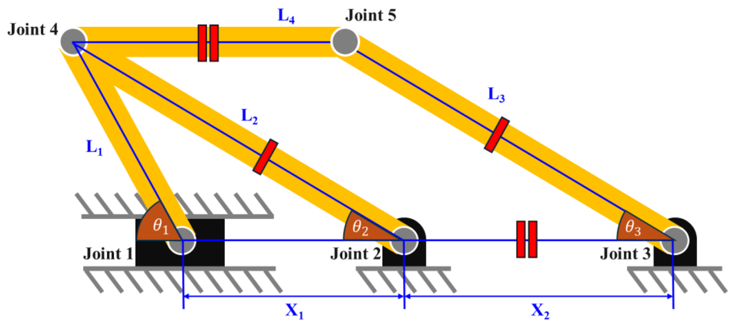
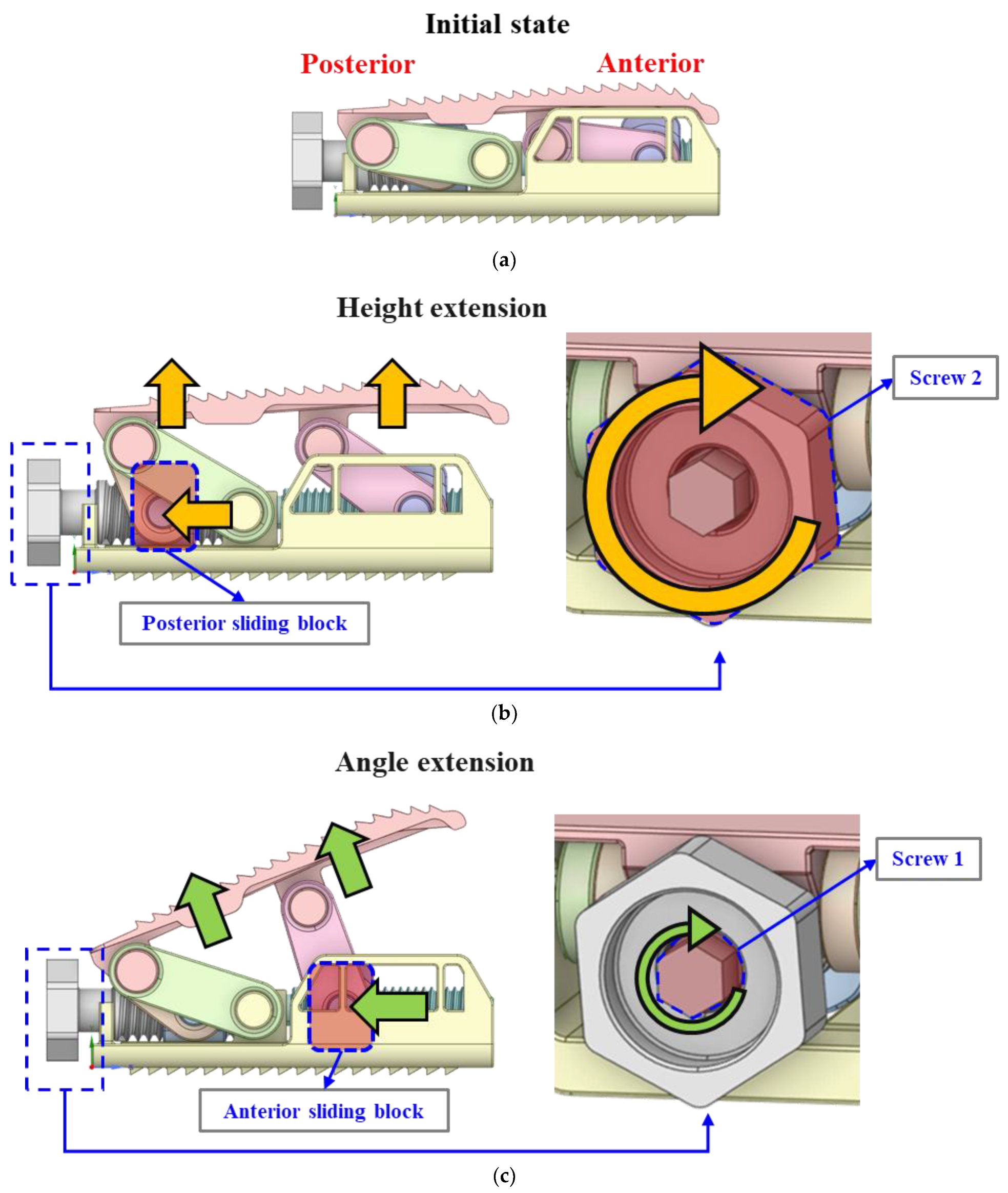
2.1. Link Mechanism for Height Extension

The height expansion of the spinal cage using a link mechanism is achieved through linkage mechanism, as shown in Figure 1. This mechanism consists of a total of five joints and connecting links. Height adjustment is accomplished by horizontally shifting the position of Joint 1, while Joints 2 and 3 remain fixed throughout process. Horizontal displacement of Joint 1 results in a corresponding change in height of Joint 4, which can be mathematically expressed. The defining position of Joint 1 as relative horizontal distance from fixed Joint 2 as depicted in Figure 1, height H of Joint 4 can be represented by the following equation.
H = L 2 s i n   ( c o s 1 X 1 2 + L 2 2 L 1 2 2 x 1 L 2 )
Equation (1) can be used to determine maximum and minimum height range of Joint 4 according to the displacement range of Joint 1. This height range, depending on displacement, provides crucial information for optimizing design to ensure sufficient height expansion.
In addition to the height variation of Joint 4, changes in position of Joint 1 also affect height of Joint 5. Typically, the height variation of Joint 5 is expressed by a highly complex equation; however, it can be simplified under certain conditions. Specifically, as illustrated in Figure 1, when linkage lengths satisfy the condition that lengths L2 and L3 are equal and lengths L4 and X2 form a parallelogram structure, the height of Joint 5 always equals the height of Joint 4. A significant advantage of this parallelogram linkage structure is that the angle between the upper and lower surfaces remains unchanged during height adjustment, effectively achieving independent control of height and angle, one of the primary goals established in this study.

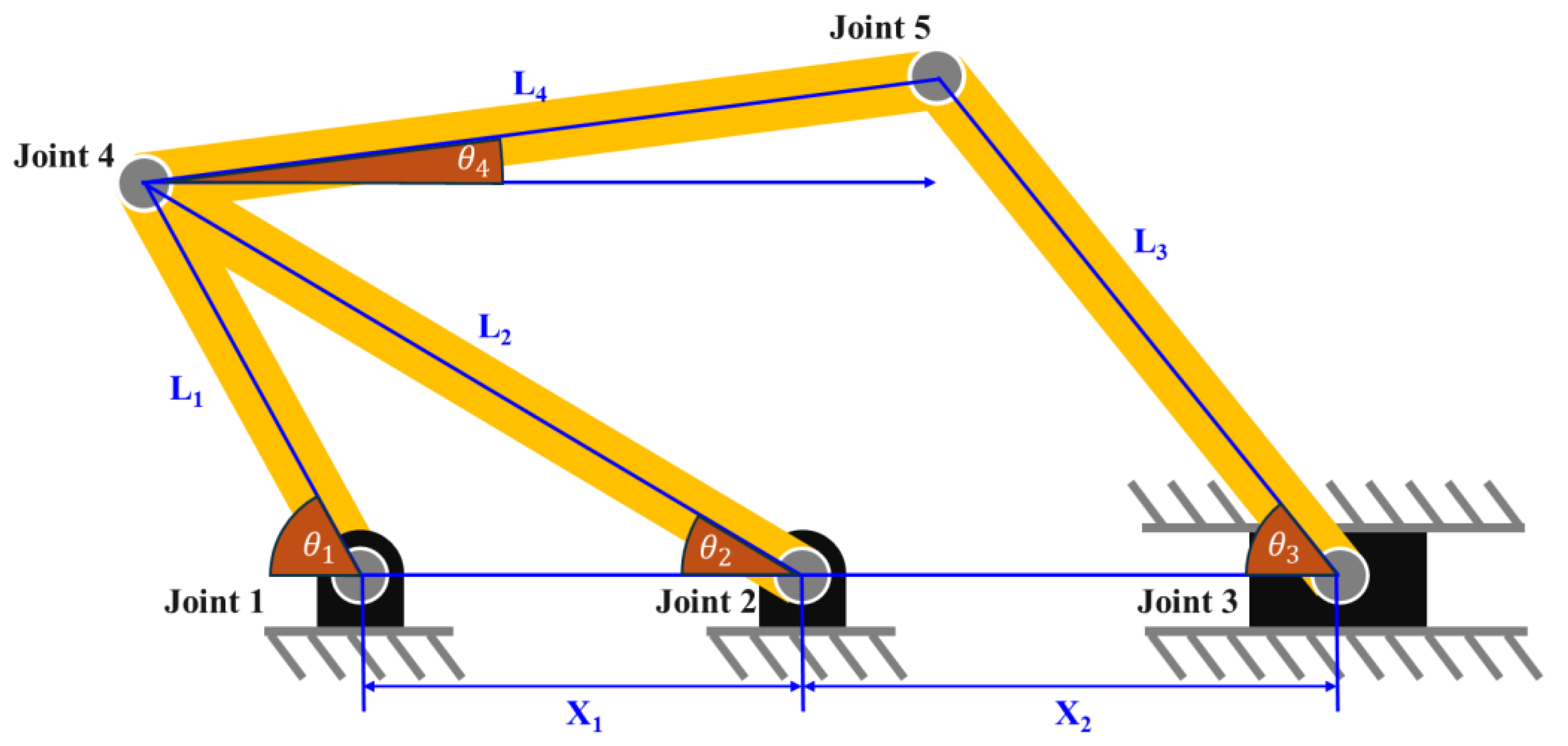
2.2. Link Mechanism for Angle Extension
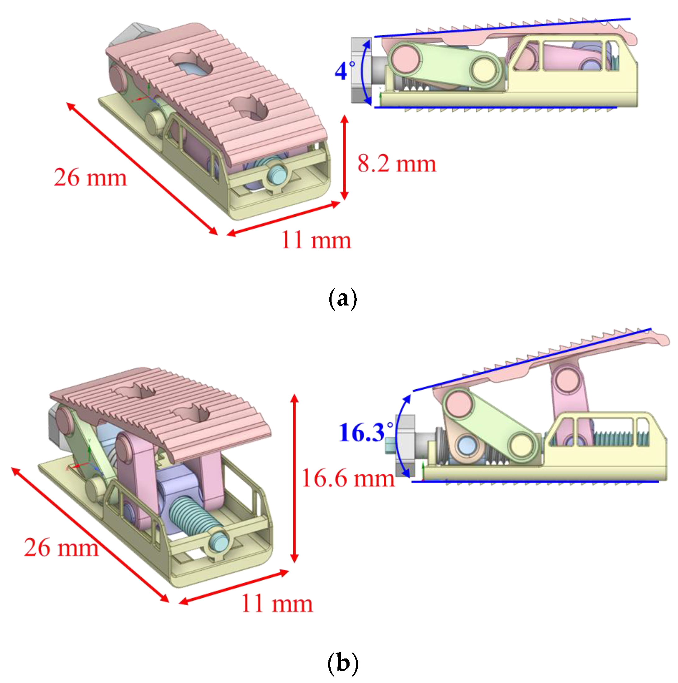
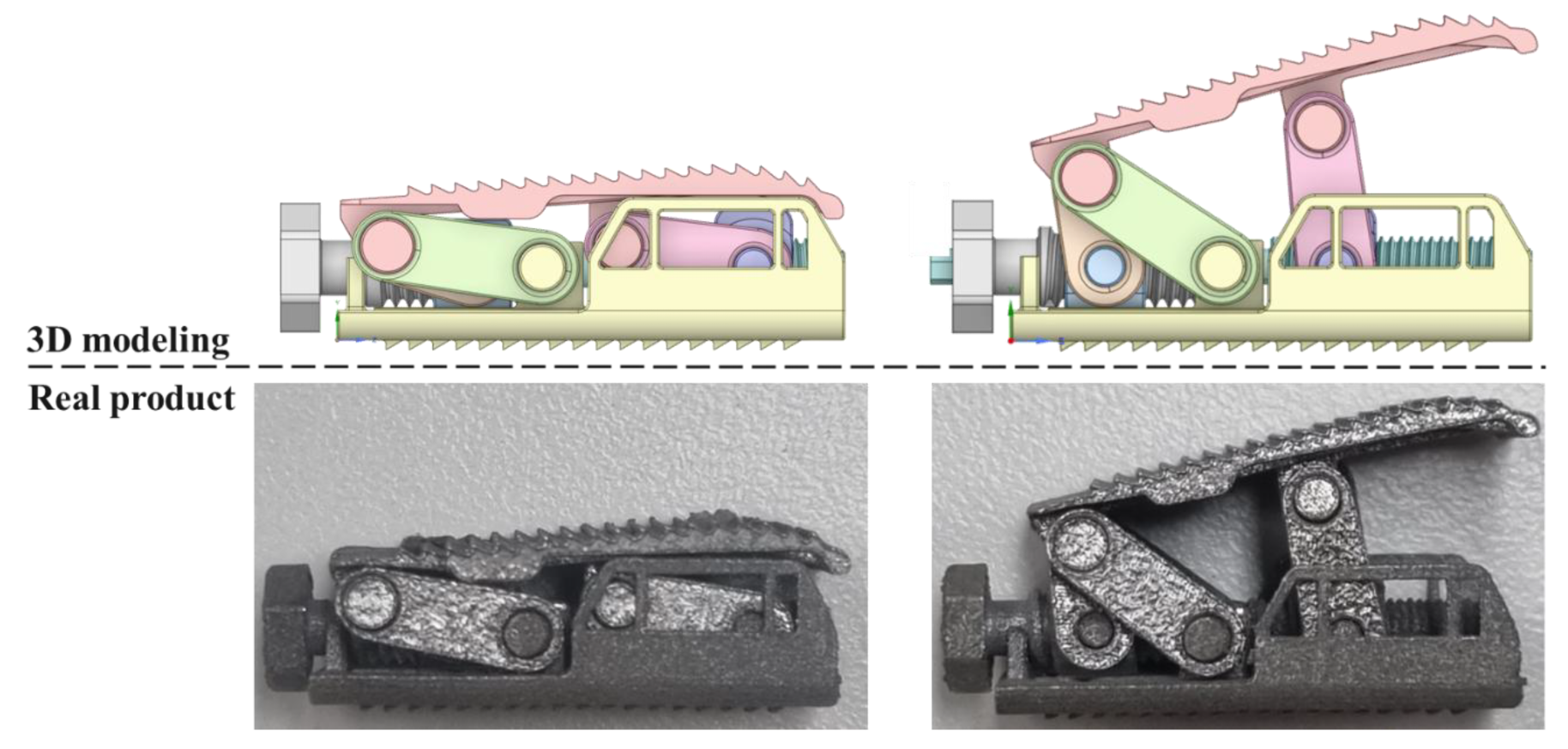
The angle adjustment of the spinal cage is achieved through the linkage mechanism illustrated in Figure 2, with the angle of the cage primarily determined by the relative heights of Joints 4 and 5. The height of Joint 5 varies depending on the position of Joint 3, while the positions of Joints 1, 2, and 4 remain unchanged due to the linkage structure. In other words, once the height of Joint 4 is set through the height adjustment process, the cage angle is controlled exclusively by adjusting the position of Joint 3. Thus, the angular change of the spinal cage with respect to the position of Joint 3 can also be expressed mathematically. Defining the position of Joint 3 as its horizontal distance relative to Joint 2, as shown in Figure 2, the spinal cage angle θ4 can be represented by the following equation:
a = L 3 2 L 2 2 L 4 2 X 2 2 2 L 2 L 4 X 2 L 4 H 2 L 2 2 H 2 L 2 2 X 2 L 2
b = 2 H L 2
c = L 3 2 L 2 2 L 4 2 X 2 2 2 L 2 L 4 X 2 L 4 H 2 L 2 2 + H 2 L 2 2 + X 2 L 2
θ 4 = 2 tan 1 ( b ± b 2 4 a c 2 a )
Using the equation above, it can be observed that spinal cage angle θ4 may have two possible values depending on the positional change of Joint 3. However, since lumbar lordosis angles are generally positive, the cage angle θ4 in practical design must also take a positive value, consistent with the lumbar lordosis angle. Therefore, Equation (5) should be modified as follows:
θ 4 = 2 tan 1 ( b + b 2 4 a c 2 a )
From Equation (6), we can determine the spinal cage angle based on the height, H, of Joint 4, which is set through height adjustment, and the position of Joint 3. Finally, by defining the adjustable range of Joint 3’s position, we can achieve a desired angular adjustment range of spinal cage and incorporate this into the design.

2.3. Final Modeling

The final prototype consists of an upper plate, a lower plate, and a linkage structure. To prevent displacement within the spine, surfaces of upper and lower plates are designed with a spiked configuration. These plates are connected via a linkage mechanism that enables simultaneous height and angle adjustments. Joints 1 and 3 of the linkage mechanism are positioned in posterior and anterior sliding blocks, respectively, and screws are used to adjust the positions of these sliding blocks. This screw-based actuation achieves one of the study’s primary goals: continuous adjustment of the height and angle.
As shown in Figure 3, the prototype’s basic specifications include a length of 26 mm, a width of 11.8 mm, an initial height of 8.2 mm, and an initial lordotic angle of 4°. Height and angle adjustments are performed through sliding blocks that house Joints 1 and 3. As shown in Figure 4, users can adjust the positions of these sliding blocks by rotating two screws using a hex driver. Screw 2 adjusts the posterior sliding block, increasing the cage height up to 11.7 mm. During this process, the linkage mechanism maintains the cage angle unchanged, thereby achieving independent height and angle adjustments. Screw 1 controls the anterior sliding block, increasing the cage height up to a maximum of 16.6 mm and extending the lordotic angle to 16.3°. Thus, the mechanism successfully meets the target specifications of a height of 14.4 mm and an angle of 12.0°. Additionally, this adjustment method is similar to those of existing expandable cages, which utilize rotational mechanisms, and has been carefully designed to minimize disruption to the established clinical workflow.
To fabricate the prototype, Ti-6Al-4V was selected as the material due to its excellent biocompatibility, high mechanical strength, and widespread use in clinical spinal implants. This titanium alloy offers a high strength-to-weight ratio and superior corrosion resistance, making it well-suited for long-term implantation in the human body. Its proven track record in orthopedic applications ensures reliability and safety, aligning with the structural requirements of spinal fusion devices [29].

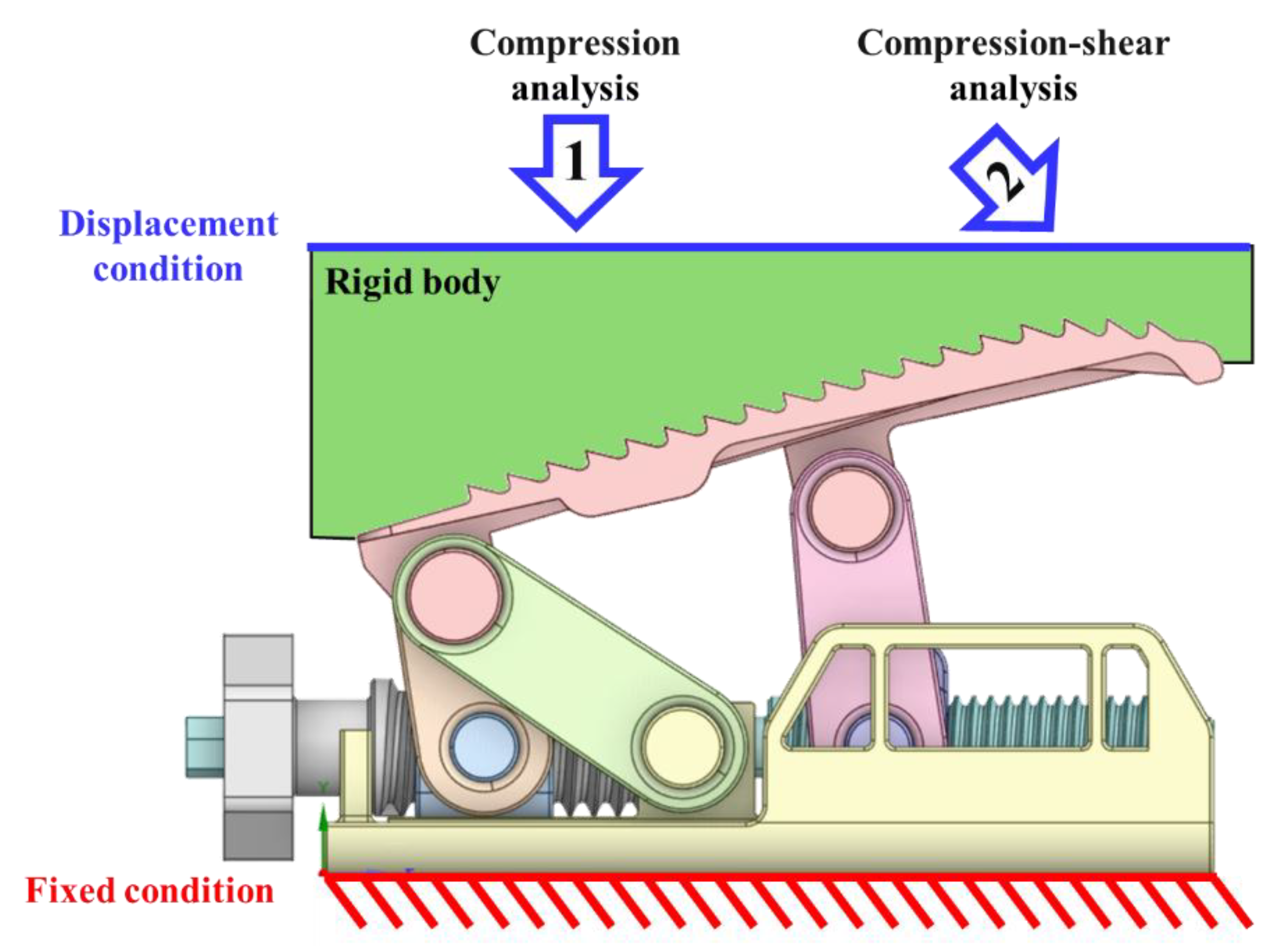
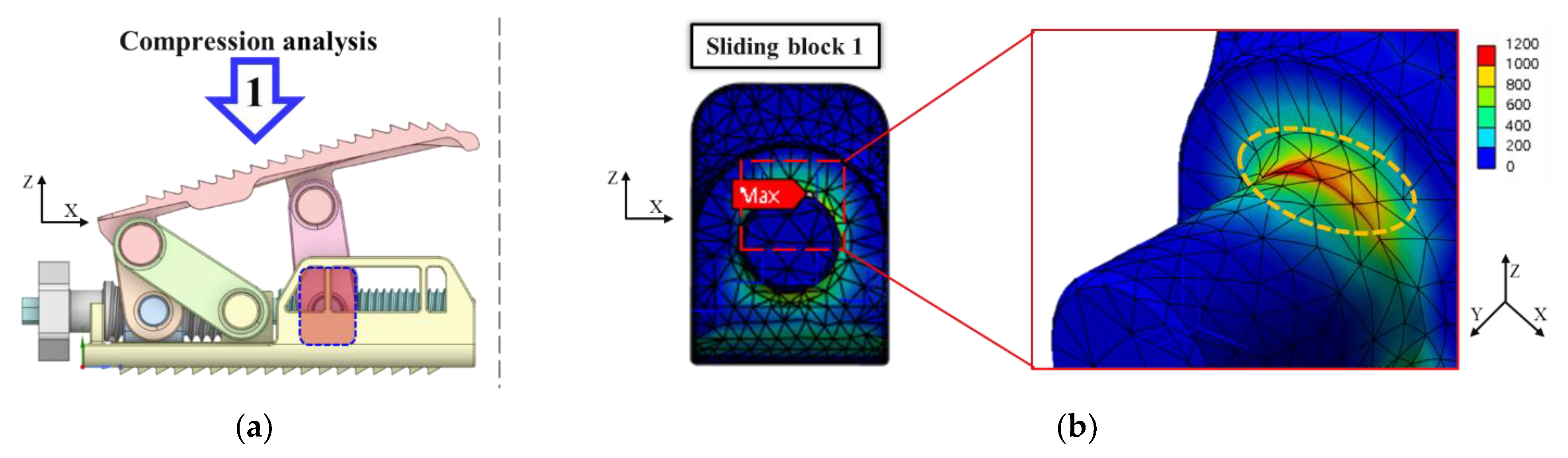
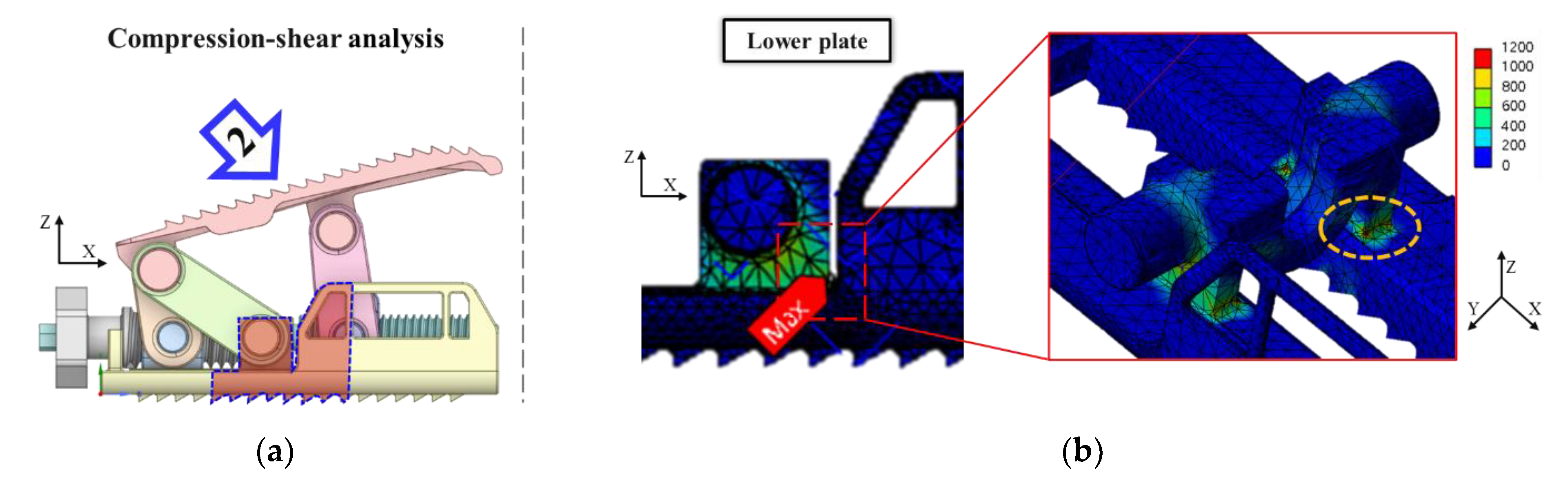
3. FEA for Mechanical Performance Verification

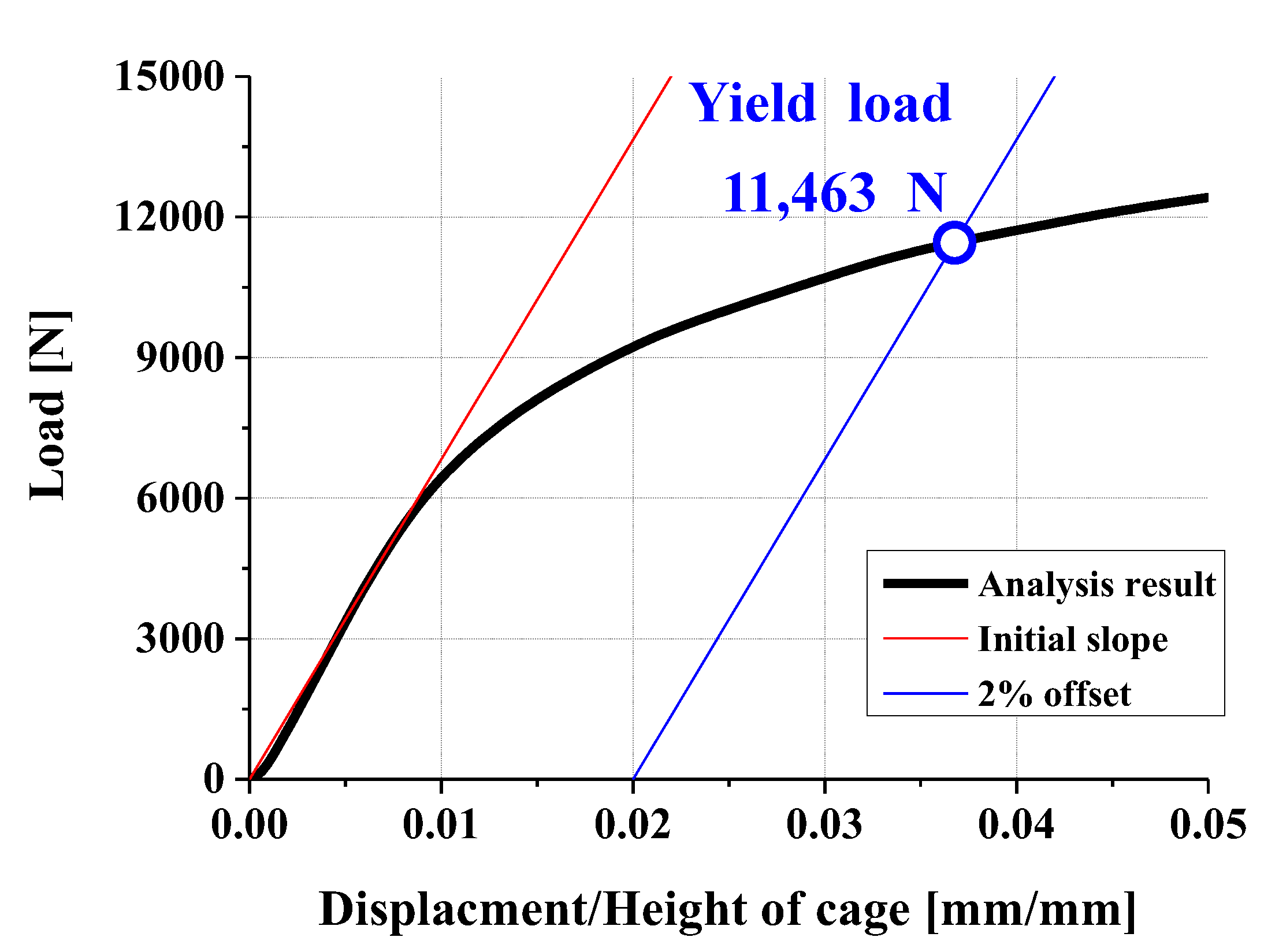
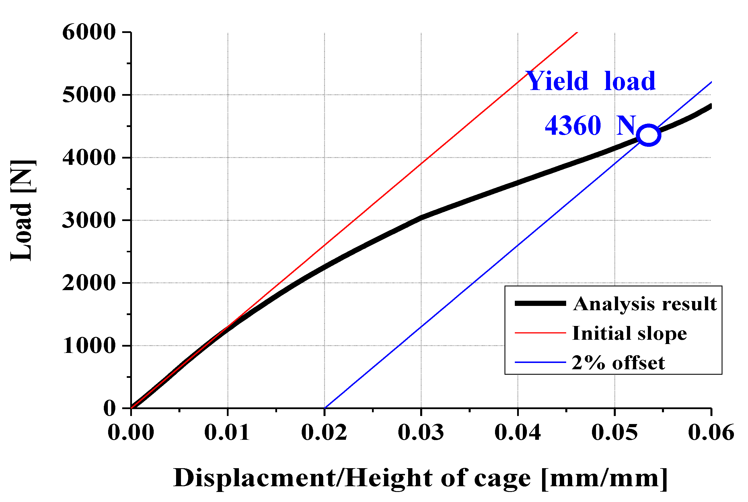
3.1. Verification Criteria

In this study, mechanical performance of spinal cage was evaluated through FEA and experiments based on ASTM F2077 testing standards. ASTM F2077 includes tests for compression, compression–shear, and torsion. Since axial rotation in the lumbar spine is not as significant as in the cervical spine, torsion testing is often excluded for lumbar cages. As this study focuses on a cage for lumbar applications, only compression and compression–shear tests were conducted.
Through these tests, the load–displacement curve of cage is obtained. From this curve, stiffness is determined as the initial slope, yield load is defined as a load causing 2% strain or 2% permanent deformation, and ultimate load is defined as the maximum load applied. These standardized tests enable evaluation of cage’s mechanical performance under consistent conditions, allowing for easy comparison between developed cage and existing designs.
As shown in Table 1, allowable mechanical performance criteria identified through ASTM F2077 tests are defined by ISO 23089-2, international standard for spinal cage mechanical performance [30]. According to ISO 23089-2, the yield load of a spinal cage should meet or exceed the performance of the bottom 5% of FDA-approved spinal cages. Based on this standard, spinal cages should demonstrate a yield load of at least 6371 N in a compression test and at least 1996 N in a compression–shear test.

3.2. FEA Model and Results

Finite element analysis was utilized for design verification of the expandable cage. Static structural analysis was performed using the Static Structural module of ANSYS 2021 R1, adhering to the ASTM F2077 standard. This process allowed us to evaluate the mechanical performance of the spinal cage.
As shown in Figure 5, analysis was conducted based on a solid model. To simplify the analysis model as much as possible, it was composed of two main components: the fixture and two expandable cages. The fixture acts as a rigid body that does not deform, representing a metal block used to secure the cage in accordance with the ASTM F2077 standard. The mesh of this analysis model consisted of tetrahedral elements, with a total of 266,649 nodes and 146,169 elements. Since the prototype of the developed model is planned to be manufactured using Ti-6Al-4V through additive manufacturing, the properties of these FEA models have been applied to all parts with tensile test results of Ti-6Al-4V produced by additive manufacturing studied in the previous literature.
The contact conditions and boundary conditions of the analysis model are defined as follows. First, for the contact conditions, the components constituting the expandable cage are defined to be in contact with each other with a friction coefficient of 0.38. Additionally, the metal block that comes into contact with spinal cage during actual experiments is treated to prevent sliding. Accordingly, a rough contact condition is applied between the fixture and the upper plate to prevent sliding.
Second, for the boundary conditions of the analyzed model, a fixed condition is applied to the bottom of lower plate to prevent the cage from moving. A displacement condition is applied to the top of the fixture to perform compression tests and compression–shear tests. The displacement applied to the top of the fixture is a total of 1 mm, which is empirically determined to evaluate yield strength in accordance with the ASTM F2077 standard. In the compression test, the cage is compressed vertically in the direction of arrow 1, as shown in Figure 5, while in the compression–shear test, the cage is compressed at a 45-degree angle in the direction of arrow 2. In this case, displacement in the direction perpendicular to the compression direction is not constrained to closely simulate the ASTM F2077 standard.
As shown in Figure 6 and Figure 7, compression analysis results are as follows: yield load is determined at the intersection of the blue line, offset by 2% from the initial slope, and for the load–displacement curve, the yield load is 11,463 N, exceeding the allowable criterion of 6371 N. Therefore, the designed expandable cage meets mechanical performance objectives under compression load. The initial yield occurs at a compression load of 1920 N on the axis of Sliding Block1.
As shown in Figure 8 and Figure 9, compression–shear analysis shows similar results. The yield load is 4360 N, surpassing the allowable criterion of 1996 N, confirming that the expandable cage also meets mechanical performance goals under compression–shear load. The initial yield under this condition occurs at a compression–shear load of 1128 N at the corner of the pillar where the lower plate axis is located.

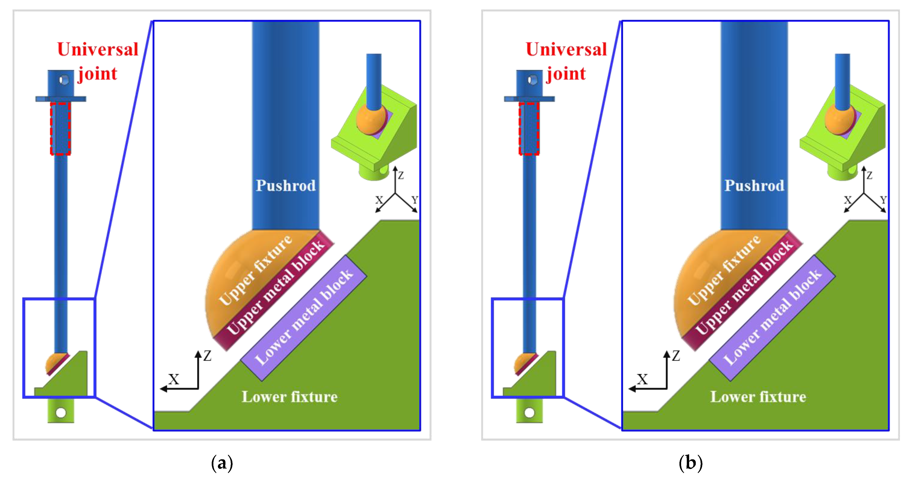
4. Compression and Compression–Shear Test

4.1. Three-Dimensional Printing

As shown in Figure 10, to conduct bench testing of FEA-verified model, a specimen was fabricated. Additive manufacturing was employed to overcome the low machinability of the Ti-6Al-4V material and to achieve a small size with complex geometries. A specimen was produced using an SLM metal 3D printer with an expected dimensional accuracy of approximately ±0.1 mm due to limitations in precision. To compensate for this tolerance and ensure smooth assembly and operation, a model with a 0.2 mm clearance was designed and fabricated.
Additionally, a dimensional accuracy of ±0.1 mm corresponds to approximately 5% of the shaft diameter of the sliding block, where load concentration is predicted based on FEM analysis. This level of tolerance can significantly affect mechanical performance. For this reason, three specimens were fabricated, and their dimensions were measured. The specimen with the smallest dimensional deviation was selected for the experiment. Therefore, the experimental results presented are based on the representative specimen that best reflects the design objectives while minimizing the influence of dimensional variation.

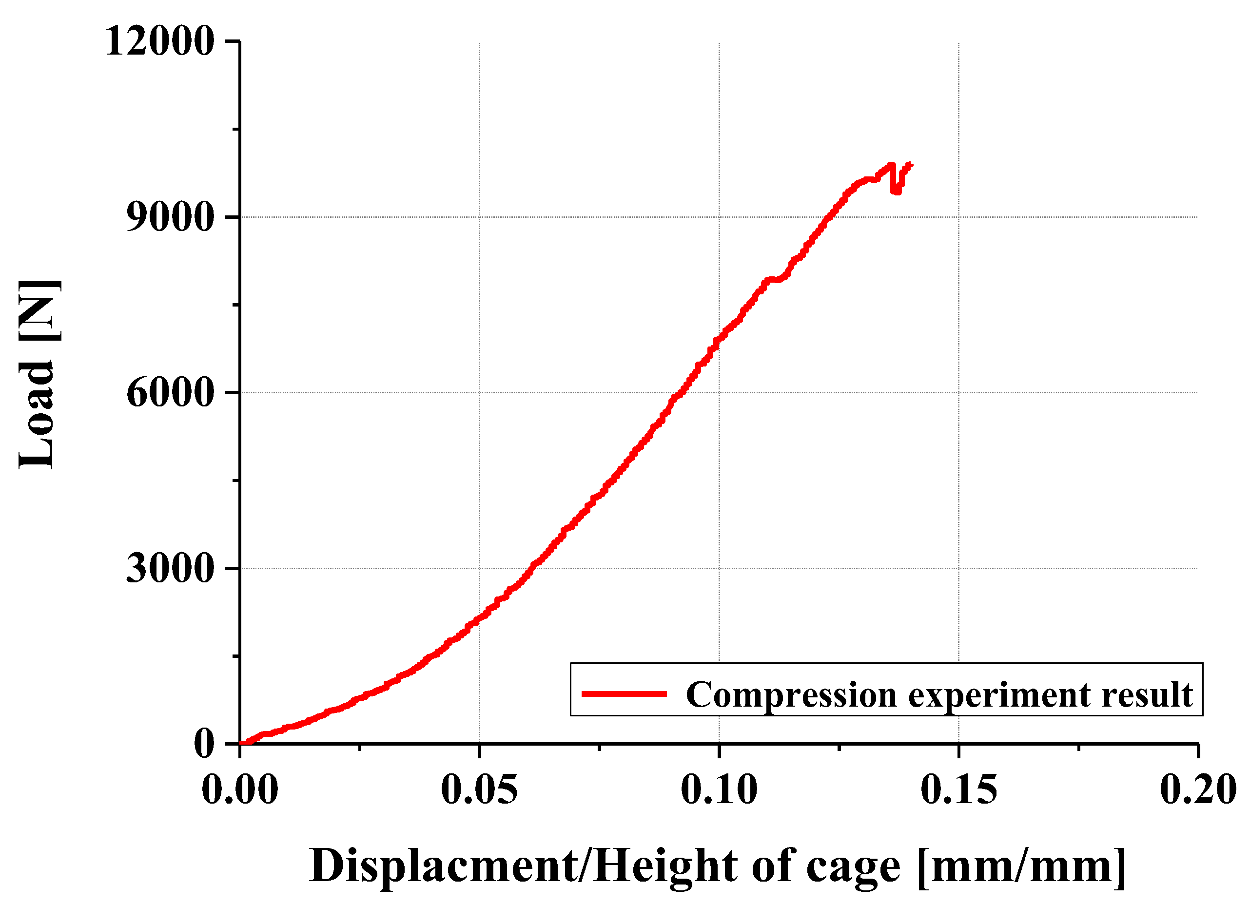
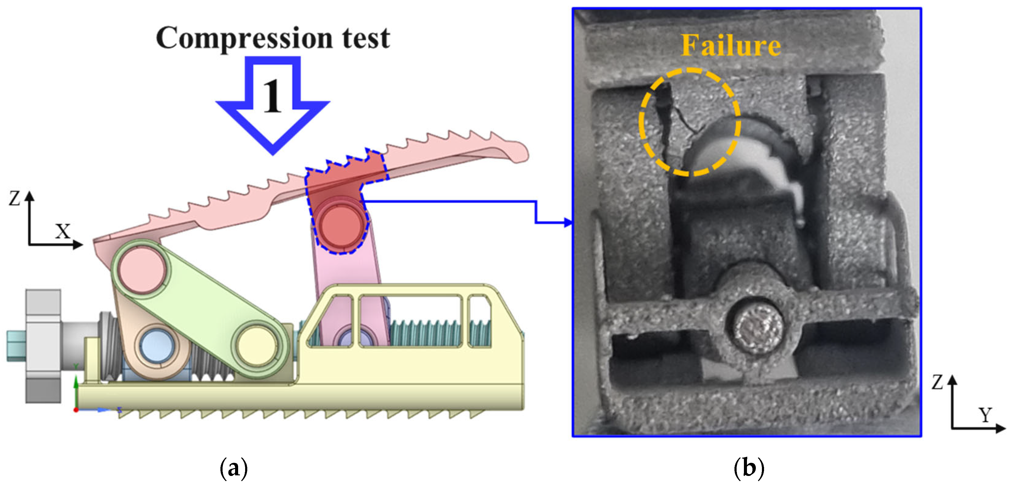
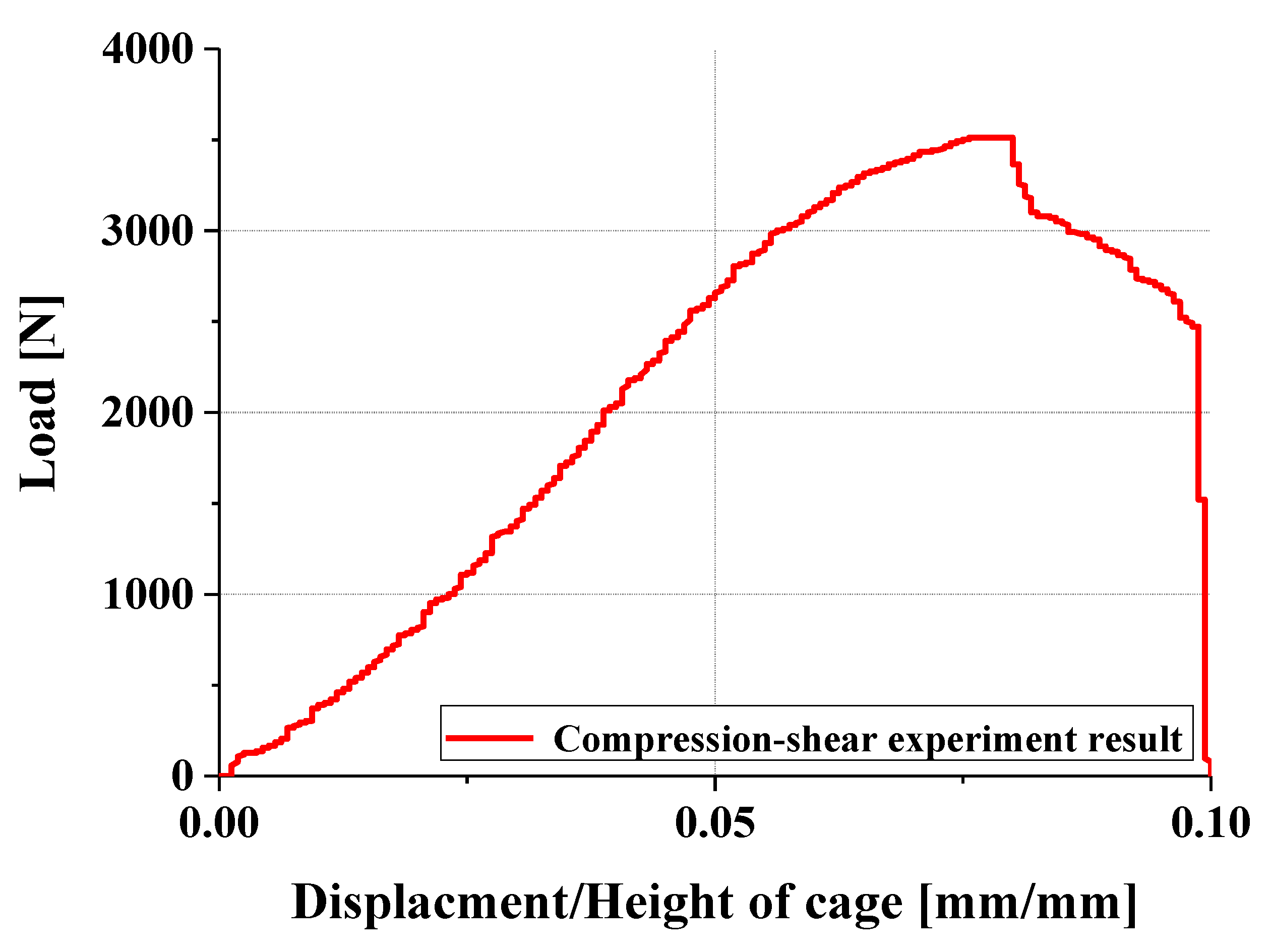
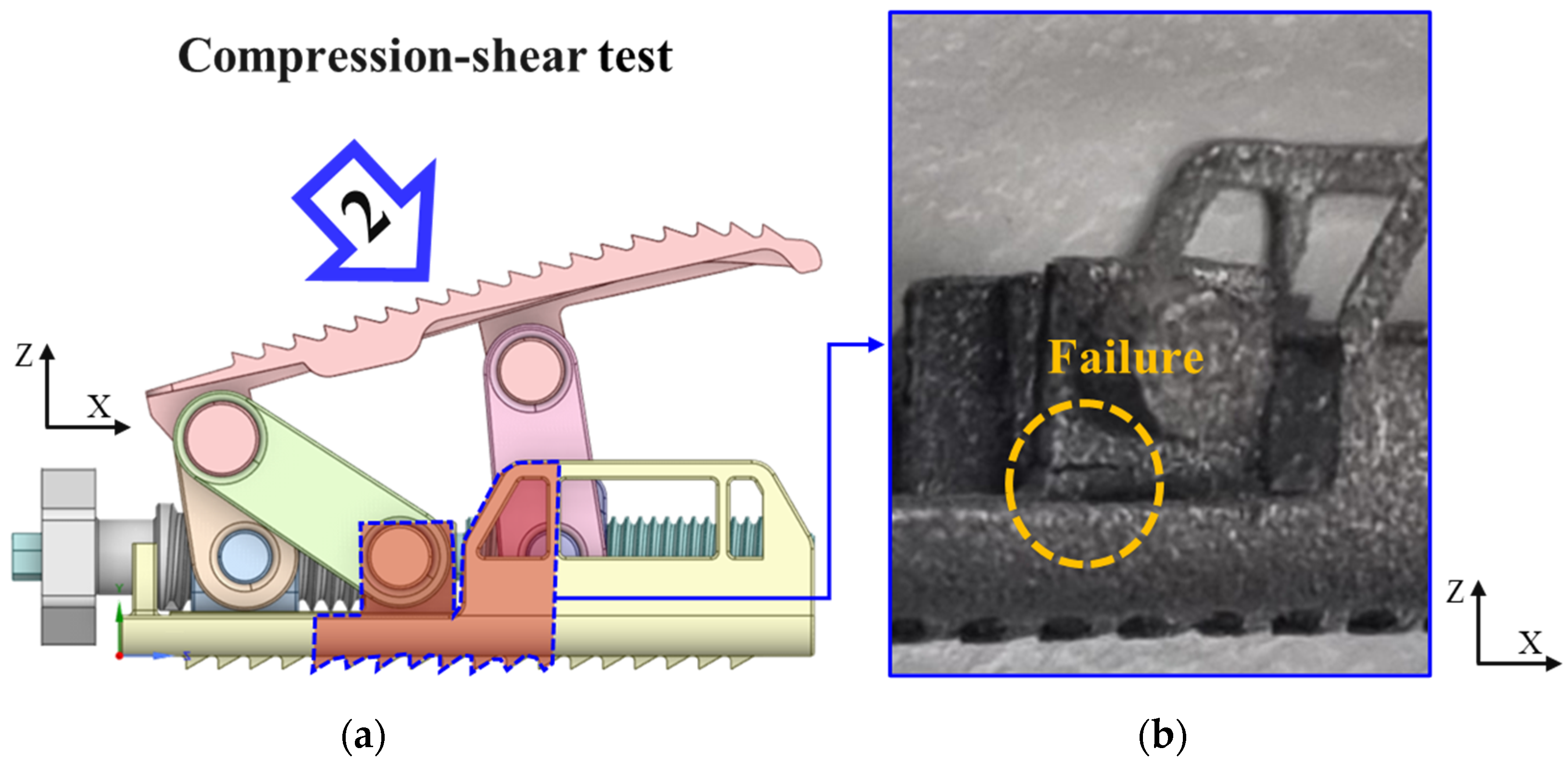
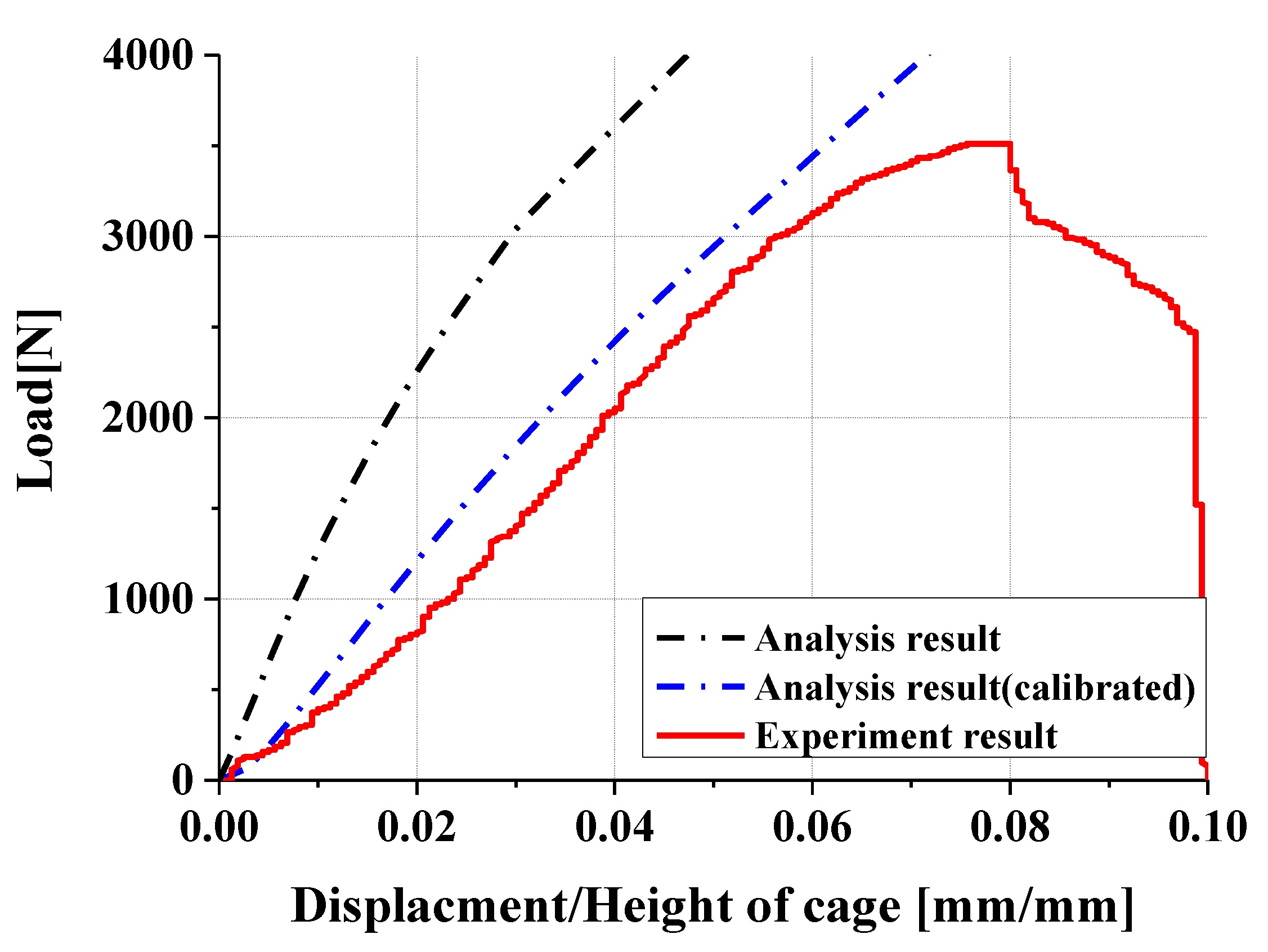
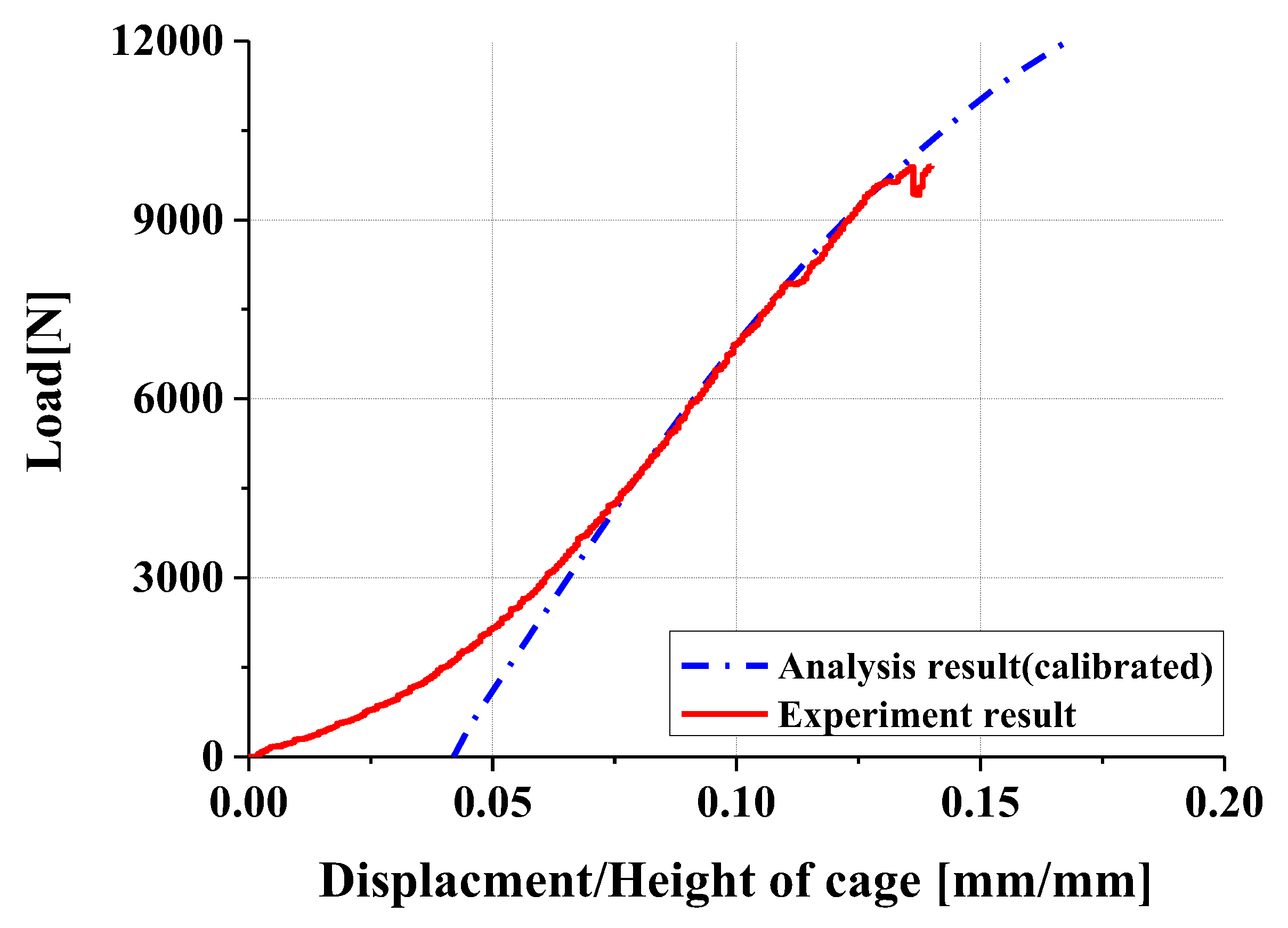
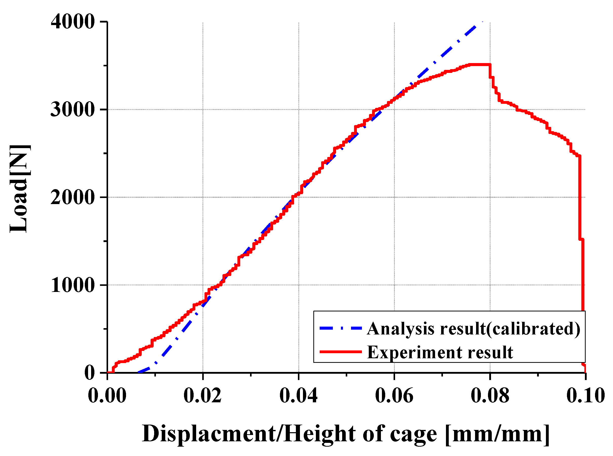
4.2. Compression and Compression–Shear Tests and Results

The bench test was conducted based on ASTM F2077, a standard for measuring mechanical performance of spinal cages, as previously mentioned [30]. The test setup is depicted in Figure 11. First, a universal joint is used to connect the pushrod to the testing machine, and a spherical joint connects the pushrod to the upper fixture. The lower fixture is fixed to the base. Metal blocks are assembled to the upper and lower fixtures, and the cage is secured to these metal blocks, which are designed to match geometric features of the cage.
In the compression test, the cage is mounted perpendicular to the pushrod axis, while in the compression–shear test, it is mounted at a 45° angle to the pushrod axis. In both cases, the center of the cage must align with the axis of the pushrod. To minimize offset between the pushrod axis and the load cell axis, the pushrod was designed to be 400 mm in length. All components of the setup were fabricated from stainless steel with an ultimate tensile strength of 1310 MPa. The load was applied at a rate of 1 mm/min up to 6 mm or until failure or loss of function occurred. This test generated the load–displacement curve of the cage. Stiffness was determined from the initial slope of the curve, and yield load was defined as a load causing 2% permanent deformation.
In compression and compression–shear tests, failure occurred before yielding load could be determined, making it impossible to derive the yielding load. As an alternative, the ultimate load was compared to the fifth percentile ultimate load of spinal cages approved by the U.S. Food and Drug Administration (FDA) to evaluate mechanical stability.
First, in compression test results, as shown in Figure 12, the ultimate load was 9888 N. This exceeds the fifth percentile ultimate load of 6989 N for FDA-approved spinal cages, indicating that current model meets performance targets in compression test. As shown in Figure 13, failure occurred at the anterior axis of the upper plate.
Next, in compression–shear test results, as shown in Figure 14, ultimate load was 3315 N, which surpasses FDA-approved fifth percentile ultimate load of 1996 N. Thus, the current model also meets performance targets in the compression–shear test. As shown in Figure 15, failure occurred at edge of the column where the axis of the lower plate is located.

5. Results and Discussions

This study successfully demonstrated the achievement of key design objectives for the expandable spinal cage. First, the cage provides sufficient height and angle expansion, ensuring the required intervertebral space and lordosis angle restoration. Second, the height and angle can be adjusted independently. While several existing cages offer height and angle adjustments in linked or fixed increments, this design allows individual control of both height and lordosis adjustments. Third, the height and angle adjustments can be continuously and finely tuned, enabling gradual adjustments during surgery to achieve precise alignment and fit, as opposed to limited incremental adjustments. The main characteristics of the proposed design are compared with existing cages in Table 2.
These improvements were made possible through the novel linkage mechanism introduced in this cage design. The internal linkage mechanism translates the surgeon’s operation into independent height and angle adjustments, while the slider component facilitates smooth, continuous tuning. Traditional rack-and-pinion or wedge designs typically offered only fixed expansion stages or lacked independent adjustment capabilities. In contrast, the spinal cage proposed in this study can be customized during surgery based on patient-specific anatomical features, allowing for sufficient disk height and spinal curvature restoration. This represents a significant improvement compared to static cages with no adjustment capabilities or conventional expandable cages with coarse incremental adjustments.
FEM analysis was utilized to predict the mechanical behavior of the expandable cage and compared with actual mechanical testing results. As shown in Figure 16 and Figure 17, differences between FEM simulations and experimental outcomes were observed. The primary cause of these differences was attributed to the deformation of the testing equipment. During experiments, the test apparatus underwent slight elastic deformation under load, which was not considered in the FEM analysis. To compensate, tests compressing only the equipment without specimens were conducted, revealing approximately 0.11 mm deformation under a 1000 N load. This data allowed for the calculation of equipment deformation corresponding to applied loads, which was then integrated into the FEM analysis for calibration.
As shown in Figure 18 and Figure 19, The calibrated FEM results closely matched the experimental data, enhancing the reliability of the FEM model. However, some discrepancies occurred in low-load regions, likely due to slight looseness caused by manufacturing and assembly tolerances in specimen. Specifically, there was a designed tolerance of 0.2 mm which was not present in the FEM model. While the FEM model assumes perfectly fitted components, the actual specimen may have had minor gaps that delayed initial contact between parts. As the load increased, these gaps closed through deformation and interlocking, resulting in load–displacement behavior that aligned with FEM predictions.
Additionally, in the actual compression test, Load drop was observed due to material fracture, which is a typical failure behavior of metallic components under high stress. However, this sudden load drop is not captured in the FEM analysis, as the simulation does not account for load drop due to fracture. As a result, the FEM results show a continued increase in load with compression, rather than a decline, leading to a divergence from experimental curve in region just before load drop.
Through FEM analysis, structural stress distributions and failure modes were predicted, demonstrating a high correlation with the failure locations and patterns observed experimentally. Under compression loading, FEM analysis predicted stress concentration and potential failure in the anterior linkage region. Correspondingly, experimental tests confirmed failure at the anterior sliding block shaft and its corresponding shaft in the upper plate, aligning with the FEM predictions.
For compression–shear loading conditions, FEM analysis predicted failure at the lower plate shaft, closely matching observed experimental failures. These findings underscore the FEM model’s capability to accurately predict structural stress distribution and failure modes, highlighting its potential for reliable performance forecasting and optimization in early design stages without relying on physical prototypes.
Mechanical performance of the expandable cage was evaluated through actual mechanical tests. Due to the inability to determine yield loads experimentally, ultimate loads were used as a criterion to compare performance with existing cages. The cage demonstrated excellent load-bearing capacity under compression, surpassing the ultimate loads of the lowest 5% of currently FDA-approved spinal cages. Additionally, under compression–shear loading, the cage similarly exceeded the lowest 5% ultimate load threshold, confirming its structural stability under various loading conditions. These results suggest that the designed cage meets the clinical load requirements effectively.
Despite these promising results, this study carries limitations. It was restricted to static load testing without performing dynamic fatigue testing. Considering that spinal cages in clinical settings endure millions of cyclic loading events, fatigue testing is essential to assess long-term durability. Future studies should perform fatigue testing following standards such as ASTM F2077.
Moreover, the current study did not evaluate in vivo applicability through clinical or animal trials. Given the necessity of verifying mechanical stability in actual physiological conditions, conducting clinical or animal experiments is critical. Hence, future research should include these tests to confirm the cage’s performance in real-world settings.

6. Conclusions

In this study, we introduced a novel linkage mechanism and slider adjustment method to design an expandable spinal cage capable of sufficient height and angle expansion, independent adjustment, and continuous fine-tuning. This design was validated through FEM analysis and mechanical testing. Key findings are summarized as follows:
  • The new linkage mechanism applied in this design enables the independent control of height and angle, a functionality that is difficult to achieve with traditional rack-and-pinion or wedge-type designs. Additionally, continuous fine-tuning facilitated by sliders allows surgeons to achieve precise alignment tailored to the anatomical characteristics of individual patients during surgery.
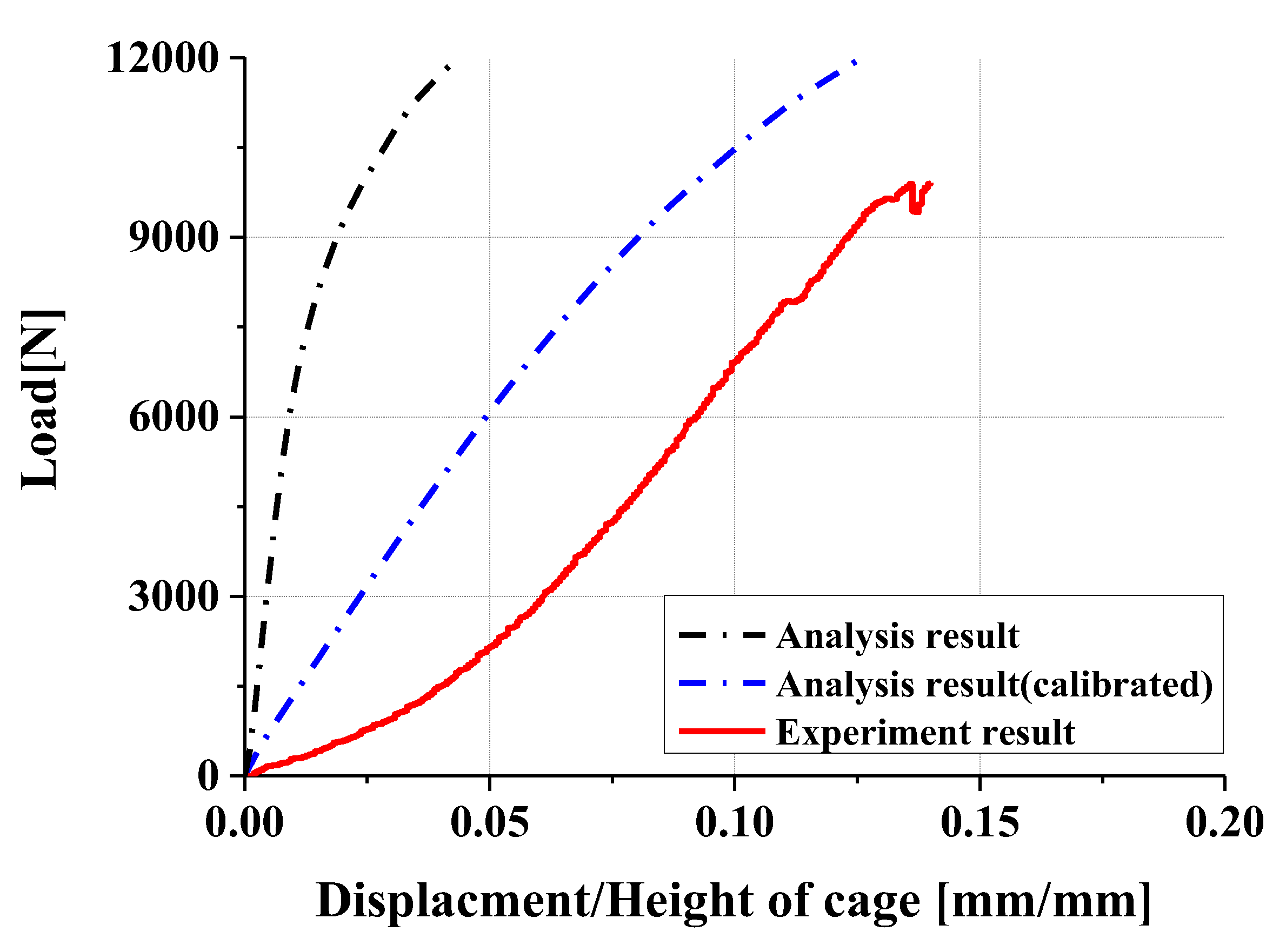
  • Experimental results showed trends similar to calibrated FEM analysis, particularly demonstrating a high correlation between two evaluation methods in predicting yield locations at anterior sliding block and lower plate shaft regions. FEM analysis was calibrated considering elastic deformation of testing apparatus, enhancing the reliability of the FEM model.
  • In compression and compression–shear tests, the designed spinal cage exhibited an ultimate load exceeding the lower fifth percentile of FDA-approved products, thereby satisfying clinical requirements. These findings confirm that proposed design offers significant improvements over existing products and demonstrates high potential for clinical application as a patient-specific spinal fusion device.
  • However, this study has several limitations. Firstly, the evaluation was limited to static load testing, without performing dynamic fatigue testing, leaving durability under prolonged cyclic loading inadequately assessed. Since real clinical environments involve tens of millions of repetitive loads, fatigue testing is necessary to confirm long-term mechanical stability. Moreover, as this research was confined to in vitro testing, clinical trials or animal studies evaluating actual in vivo applicability have not yet been conducted. Future research should include such validation processes to establish clinical efficacy.
Overall, this study provides essential baseline data for design and performance assessment of expandable spinal cages, highlighting the potential for developing safer and more effective spinal fusion instruments. Future dynamic fatigue testing and clinical studies are needed to evaluate long-term durability and real-world clinical applicability, paving the way for advancements in spinal fusion technology.

Author Contributions

Conceptualization, J.Y.; methodology, C.P. and T.T.K.D.; validation, S.-J.P., D.-S.C. and S.H.C.; formal analysis, C.P.; investigation, C.P. and T.T.K.D.; resources, J.Y.; writing—original draft, C.P.; writing—review & editing, S.-J.P., D.-S.C., S.H.C. and J.Y.; supervision, J.Y.; funding acquisition, J.Y. All authors have read and agreed to the published version of the manuscript.

Funding

This research was financially supported by the Ministry of Trade, Industry, and Energy (MOTIE), Korea, under the “Innovative Digital Manufacturing Platform” program (reference number P00223311) supervised by the Korean Institute for the Advancement of Technology (KIAT). This work was also supported by the Ministry of Trade, Industry, and Energy (MOTIE), Korea, under the “170 k closed section roll forming and free curvature bending technology development for electric vehicle body” grant (reference number 20022814) supervised by the Korea Institute for Advancement of Technology (KIAT). Finally, this work was supported by the National Research Foundation of Korea (NRF) grant funded by the Korea government (MSIT) (RS-2025-00555072). The authors have no conflicts of interest to declare.

Institutional Review Board Statement

Not applicable.

Informed Consent Statement

Not applicable.

Data Availability Statement

The original contributions presented in this study are included in the article. Further inquiries can be directed to the corresponding author.

Conflicts of Interest

The authors declare no conflict of interest.

References

  1. Roberts, S.; Evans, H.; Trivedi, J.; Menage, J. Histology and pathology of human intervertebral disc. J. Bone Jt. Surg. 2006, 88 (Suppl. S2), 10–14. [Google Scholar]
  2. Mirza, S.K.; White, A.A. Anatomy of intervertebral disc and pathophysiology of herniated disc disease. J. Clin. Laser Med. Surg. 1995, 13, 131–142. [Google Scholar] [CrossRef] [PubMed]
  3. Cassidy, J.D.; Loback, D.; Yong-Hing, K.; Tchang, S. Intervertebral disc herniation. Spine 1992, 17, 570–574. [Google Scholar]
  4. Deyo, R.A.; Mirza, S.K. Clinical practice. herniated lumbar intervertebral disk. N. Engl. J. Med. 2016, 374, 1763–1772. [Google Scholar] [CrossRef]
  5. Hasan, M.; Alam, S.; Jahan, S.; Chowdhury, A.A.M.; Junayed, S.A.; Khan, M.R.; Hasan, Z. Outcome of prolapse lumbar intervertebral disc (PLID) surgery: A study at a district-level private hospital in Bangladesh. J. Spine Res. Surg. 2024, 6, 109–113. [Google Scholar] [CrossRef]
  6. Purushotham, S.; Hodson, N.; Greig, C.; Gardner, A.; Falla, D. Microscopic changes in the multifidus muscle in people with low back pain associated with lumbar disc herniation. Sci. Rep. 2024, 14, 1–13. [Google Scholar] [CrossRef]
  7. Lee, J.S.; Lee, S.-B.; Kang, K.-Y.; Oh, S.H.; Chae, D.-S. Review of recent treatment strategies for lumbar disc herniation (LDH) focusing on nonsurgical and regenerative therapies. J. Clin. Med. 2025, 14, 1196. [Google Scholar] [CrossRef]
  8. Alam, K.Q.; Sahu, N.; Gulia, A.; Kumar, R.; Kohli, G.; Kumar, S. Assessment of pain and neurological involvement in patients with lumbar intervertebral disc prolapse who underwent fenestration discectomy. Int. J. Life Sci. 2024, 10, 6481–6488. [Google Scholar] [CrossRef]
  9. Gopi, J.; Mammu, S.; Jayan, A.; Jamshad, O.P.; Fijad, N.R.; Vaisakh, V.K. Transformative spinal surgery: Lateral position unilateral biportal endoscopic discectomy. J. Orthop. Case Rep. 2025, 15, 67–72. [Google Scholar] [CrossRef]
  10. Blumenthal, S.L.; Ohnmeiss, D.D. Intervertebral cages for degenerative spinal diseases. Spine J. 2003, 3, 301–309. [Google Scholar] [CrossRef]
  11. Laubach, M.; Kobbe, P.; Hutmacher, D.W. Biodegradable interbody cages for lumbar spine fusion: Current concepts and future directions. Biomaterials 2022, 288, 121699. [Google Scholar] [CrossRef] [PubMed]
  12. Sun, J.; Liu, S.-S.; Zou, D.; Ni, R.-H.; Wei, C.-B.; Wang, H.; Li, W.-S. A novel porous interbody fusion cage modified by microarc oxidation and hydrothermal treatment technology accelerate osseointegration and spinal fusion in sheep. RSC Adv. 2024, 14, 31966–31978. [Google Scholar] [CrossRef] [PubMed]
  13. Delfini, R.; Landi, A.; Mancarella, C.; Gregori, F. (Eds.) Modern Thoraco-Lumbar Implants for Spinal Fusion; Springer International Publishing: Vienna, Austria, 2018. [Google Scholar]
  14. Dave, B.R.; Marathe, N.; Mayi, S.; Degulmadi, D.; Rai, R.R.; Patil, S.; Jadav, K.; Bali, S.K.; Kumar, A.; Meena, U.; et al. Does conventional open TLIF cause more muscle injury when compared to minimally invasive TLIF?—A prospective single center analysis. Glob. Spine J. 2024, 14, 93–100. [Google Scholar] [CrossRef] [PubMed]
  15. Prabhu, M.C.; Jacob, K.C.; Patel, M.R.; Pawlowski, H.; Vanjani, N.N.; Singh, K. History and evolution of the minimally invasive transforaminal lumbar interbody fusion. Neurospine 2022, 19, 479–491. [Google Scholar] [CrossRef]
  16. Chang, S.Y.; Kang, D.-H.; Cho, S.K. Innovative developments in lumbar interbody cage materials and design: A comprehensive narrative review. Asian Spine J. 2023, 18, 444–457. [Google Scholar] [CrossRef]
  17. Lewandrowski, K.-U.; Vira, S.; Elfar, J.C.; Lorio, M.P. Advancements in custom 3D-printed titanium interbody spinal fusion cages and their relevance in personalized spine care. J. Pers. Med. 2024, 14, 809. [Google Scholar] [CrossRef]
  18. Iqbal, J.; Zafar, Z.; Skandalakis, G.; Kuruba, V.; Madan, S.; Kazim, S.F.; Bowers, C.A. Recent advances of 3D-printing in spine surgery. Surg. Neurol. Int. 2024, 15, 297. [Google Scholar] [CrossRef]
  19. Alimi, M.; Shin, B.; Macielak, M.; Hofstetter, C.P.; Njoku, I.; Tsiouris, A.J.; Elowitz, E.; Härtl, R. Expandable polyaryl-ether-ether-ketone spacers for interbody distraction in the lumbar spine. Glob. Spine J. 2015, 5, 169–178. [Google Scholar] [CrossRef]
  20. Kim, J.W.; Park, H.C.; Yoon, S.H.; Oh, S.H.; Roh, S.W.; Rim, D.C.; Kim, T.S. A multi-center clinical study of posterior lumbar interbody fusion with the expandable stand-alone cage (Tyche® Cage) for degenerative lumbar spinal disorders. J. Korean Neurosurg. Soc. 2007, 42, 251–257. [Google Scholar] [CrossRef]
  21. Jitpakdee, K.; Sommer, F.; Gouveia, E.; Mykolajtchuk, C.; Boadi, B.; Berger, J.; Hussain, I.; Härtl, R. Expandable cages that expand both height and lordosis provide improved immediate effect on sagittal alignment and short-term clinical outcomes following minimally invasive transforaminal lumbar interbody fusion (MIS TLIF). J. Spine Surg. 2024, 10, 55–67. [Google Scholar] [CrossRef]
  22. Moon, E.-S.; Kim, N.-H.; Park, J.-O.; Park, S.-Y.; Kim, H.-J.; Choi, W.-J.; Han, C.-W.; Kim, H.-S.; Lee, H.-M.; Moon, S.-H. Radiographic morphometry of lumbar intervertebral disc space in normal Korean. J. Korean Soc. Spine Surg. 2007, 14, 129–136. [Google Scholar] [CrossRef]
  23. Kim, D.-S.; Kim, Y.-M.; Choi, E.-S.; Shon, H.-C.; Park, K.-J.; Park, G.-K.; Lee, E.-M.; Cui, H.-S. Shape and motion of each lumbar segment in normal Korean Adults. J. Korean Orthop. Assoc. 2008, 43, 595–600. [Google Scholar] [CrossRef]
  24. Park, D.Y.; Heo, D.H. The use of dual direction expandable titanium cage with biportal endoscopic transforaminal lumbar interbody fusion: A technical consideration with preliminary results. Neurospine 2023, 20, 110–118. [Google Scholar] [CrossRef] [PubMed]
  25. Emstad, E.; Del Monaco, D.C.; Fielding, L.C.; Block, J.E. VariLift® interbody fusion system: Expandable, standalone interbody fusion. Med. Devices Evid. Res. 2015, 8, 219–230. [Google Scholar]
  26. Neely, W.F.; Fichtel, F.; Del Monaco, D.C.; Block, J.E. Treatment of symptomatic lumbar disc degeneration with VariLift-L interbody fusion system: Retro-spective review of 470 cases. Int. J. Spine Surgery 2016, 10, 15. [Google Scholar] [CrossRef]
  27. Orr, D.J.; Payne, C.; Jones, H.; Anderson, J.; Sperry, A.; Sargent, B.; Frankel, B.M.; Howell, L.L.; Bowden, A.E. Leveraging compliance to design a minimally invasive, expandable interbody cage capable of customized anatomical fit for spinal fusion surgery. J. Med. Devices 2024, 18, 1–30. [Google Scholar] [CrossRef]
  28. ASTM F2077-20; Standard Test Methods for Intervertebral Body Fusion Devices. ASTM International: West Conshohocken, PA, USA, 2020.
  29. Warburton, A.; Girdler, S.J.; Mikhail, C.M.; Ahn, A.; Cho, S.K. Biomaterials in spinal implants: A review. Neurospine 2019, 17, 101–110. [Google Scholar] [CrossRef] [PubMed] [PubMed Central]
  30. ISO 23089–2:2021; Implants for Surgery—Preclinical Mechanical Assessment of Spinal Implants and Particular Requirements—Part 2: Spinal in-Tervertebral Body Fusion Devices. International Organization for Standardization: Geneva, Switzerland, 2021.
Figure 1. Link mechanism for height extension.
Applsci 15 06323 g001
Figure 2. Link mechanism for angle extension.
Applsci 15 06323 g002
Figure 3. Modeling of expandable cage. (a) Initial state. (b) Maximum extended state.
Applsci 15 06323 g003
Figure 4. Expansion method of spinal cage. (a) Posterior and anterior in initial state. (b) Height extension. (c) Angle extension.
Applsci 15 06323 g004
Figure 5. Boundary conditions for compressive analysis according to ASTM F2077 conditions.
Applsci 15 06323 g005
Figure 6. Load–displacement curve from compression analysis.
Applsci 15 06323 g006
Figure 7. Initial yield in compression analysis. (a) Part where initial yield occurred. (b) Area where yield occurred.
Applsci 15 06323 g007
Figure 8. Load–displacement curve from compression–shear analysis.
Applsci 15 06323 g008
Figure 9. Initial yield in compression–shear analysis. (a) Part where initial yield occurred. (b) Area where yield occurred.
Applsci 15 06323 g009
Figure 10. 3D-printed expandable cage comparison with 3D modeling.
Applsci 15 06323 g010
Figure 11. Experimental setup for mechanical test with ASTM F2077 condition. (a) Compression test. (b) Compression–shear test.
Applsci 15 06323 g011
Figure 12. Load–displacement curve from compression test.
Applsci 15 06323 g012
Figure 13. Failure in compression test. (a) Part where failure occurred. (b) Area where failure occurred.
Applsci 15 06323 g013
Figure 14. Load–displacement curve from compression–shear test.
Applsci 15 06323 g014
Figure 15. Failure in compression–shear test. (a) Part where failure occurred. (b) Area where failure occurred.
Applsci 15 06323 g015
Figure 16. Comparison of compression experiment result with calibrated analysis result.
Applsci 15 06323 g016
Figure 17. Comparison of compression–shear experiment results with calibrated analysis results.
Applsci 15 06323 g017
Figure 18. Shifted compression analysis results to compare trends in analysis and experimental results.
Applsci 15 06323 g018
Figure 19. Shifted compression–shear analysis results to compare trends in analysis and experimental results.
Applsci 15 06323 g019
Table 1. The bottom 5% of mechanical performance of FDA-approved spinal cage.
TestParameterValue
Static axial compressionStiffness (N/mm)5914
Yield load (N)6371
Ultimate load (N)6989
Static compression–shearStiffness (N/mm)1435
Yield load (N)1996
Ultimate load (N)2147
Table 2. Comparison with existing model.
ModelHeight
Adjustable Range
Angle
Adjustable Range
Independent
Adjustment
Continuous
Adjustment
Our study8.4 mm12.3°PossiblePossible
Tyche [20]2 mmImpossibleImpossible
Rise [21]7 mmImpossiblePossible
Sable [21]8 mm22°ImpossiblePossible
Orr et al. [27]4 mm10°ImpossibleImpossible
Disclaimer/Publisher’s Note: The statements, opinions and data contained in all publications are solely those of the individual author(s) and contributor(s) and not of MDPI and/or the editor(s). MDPI and/or the editor(s) disclaim responsibility for any injury to people or property resulting from any ideas, methods, instructions or products referred to in the content.

