

Research on Laser Radar Inspection Station Planning of Vehicle Body-In-White (BIW) with Complex Constraints

Abstract
1. Introduction
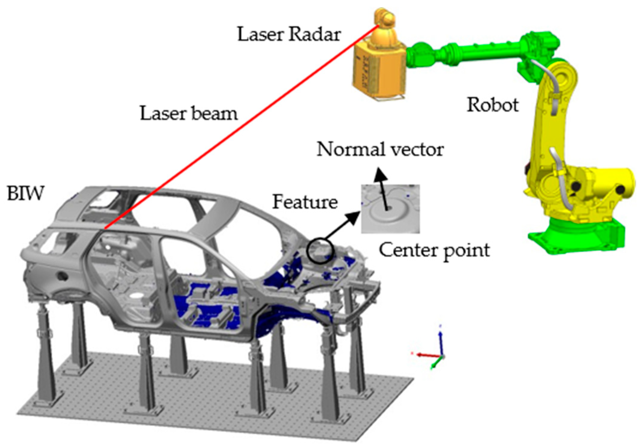
2. Engineering Problem for Laser Radar Station Planning of BIW Inspection
3. Measurement Constraints for BIW Inspection
3.1. Position Constraints of Station Planning
- A local coordinate system is assigned for each measuring feature. The origin is the center point (Fi). The Z axis is along the normal vector pointing outward from the material surface at Fi;
- The K-means++ algorithm is used to cluster feasible regions. The number of features in each cluster is constrained to a manageable size;
- In the local coordinate system of the feature, a point denoted as is defined:
- 4.
- The transformation matrix from the local coordinate to the inspection coordinate is denoted as T. The point () in the inspection coordinate system is denoted as :
- 5.
- The distortion function in clustering is J, and μc is the centroid of a cluster:
- 6.
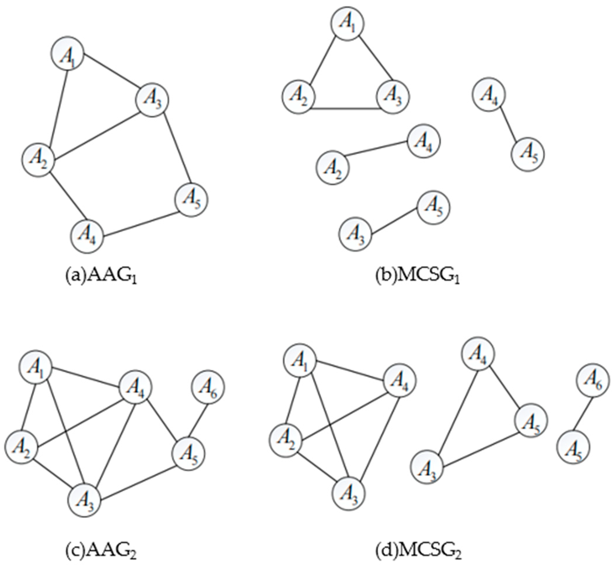
- The clustering result is denoted as Gi. In each Gi, the intersections of the feasible regions are checked to construct the AAGi.
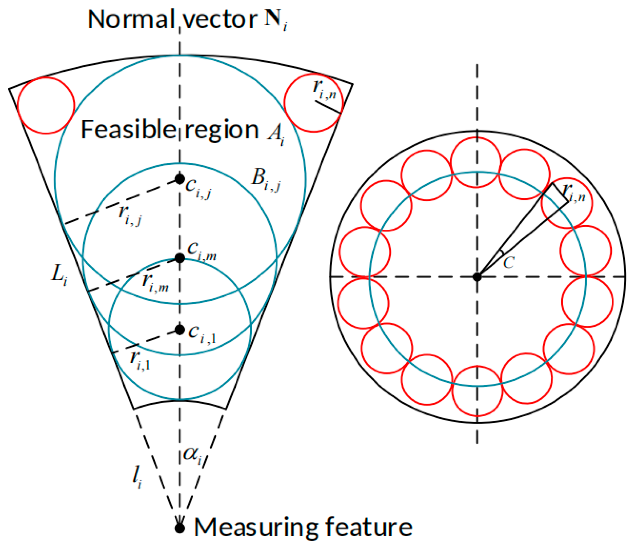
- The feasible region is simplified into a group of basic spherical regions and supplementary spherical regions which are denoted as follows:where the sphere’s center coordinates and radius, respectively. The number of basic spherical regions is m:
- 2.
- In the supplementary spherical regions, and ri,n yield the following equations:
- Two feasible regions (Ai and Am) are discretized into two groups of spherical regions. They are sorted into the sets below, corresponding to Ai and Am:
- 2.
- The Bi,j and Bm,n are traversed, and each spherical region in set Bi,j is combined with every spherical region in Bm,n. The combination group is denoted as ;
- 3.
- If any combination in yields to Equation (16), the feasible region (Ai) intersects with Am. If not, yields to Equation (16), and the feasible region (Ai) does not intersect with Am:
- 4.
- If two feasible regions (Ai and Am) are intersected, an edge, denoted as E (Ai, Am), is added between corresponding vertexes, representing feasible regions, in the attributed adjacency graph;
- 5.
- The AAGi is built up when each feasible region has been checked with the others in cluster Gi;
- 6.
- In the AAGi, the maximal complete subgraphs are identified, which are denoted as MCSGi,j. The features to be measured in MCSGi,j have shared feasible regions;
- Clustering Features: the features to be measured are clustered into Gi using the clustering algorithm described previously;
- Approximating Feasible Regions: the feasible region (Ai) of feature Fi is discretized into a set of spherical regions (Bi,j) through feasible region approximation;
- Constructing AAG Subgraphs: The intersection between the feasible regions (Ai) within Gi is checked to construct the attributed adjacency graph (AAGi). The maximal complete subgraphs (MCSGi,j) in the AAGi represent the shared feasible regions;
- Defining Position Constraints: the station’s position constraint is determined by evaluating the distance between the station and the approximated spherical regions (Bi,j).
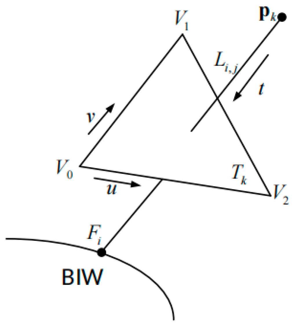
3.2. Interference Constraints of Station Planning
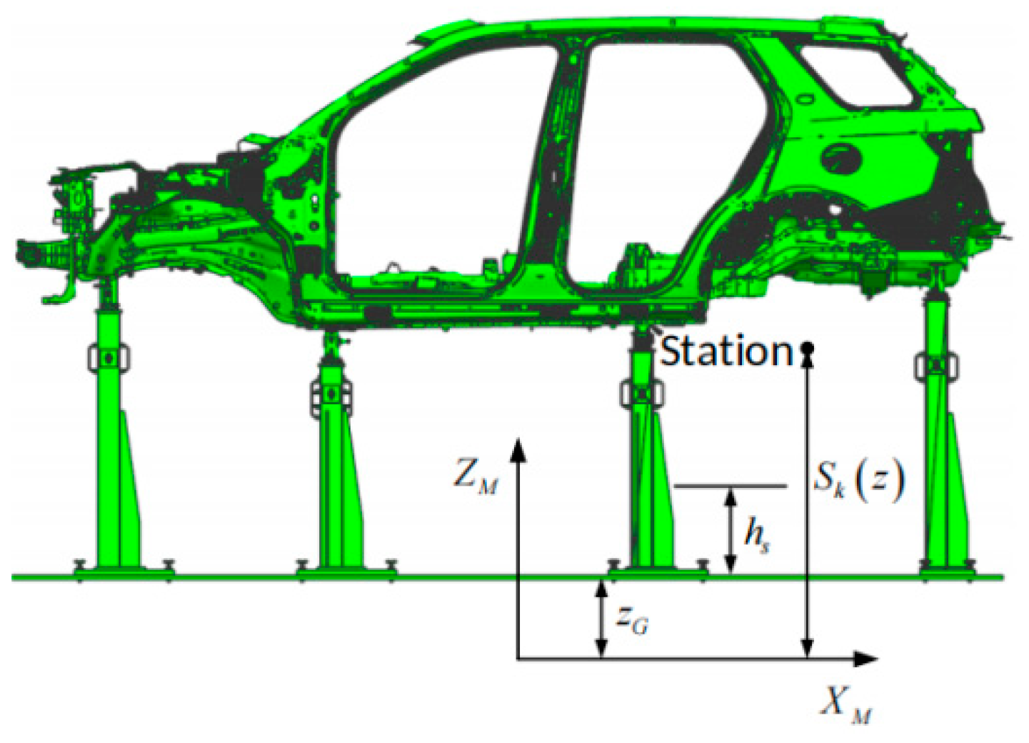
3.3. Spatial Constraints for BIW Inspection
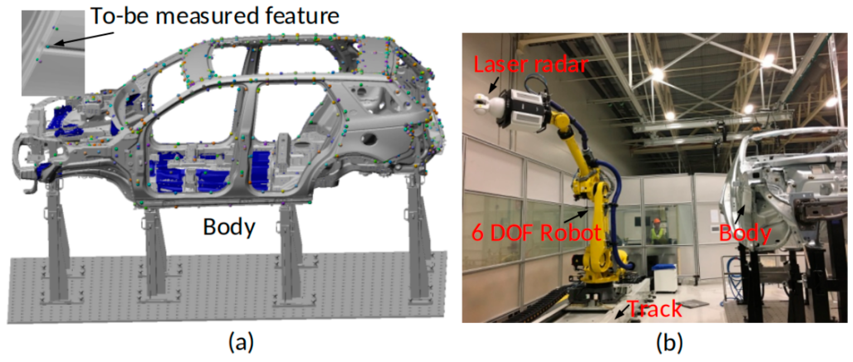
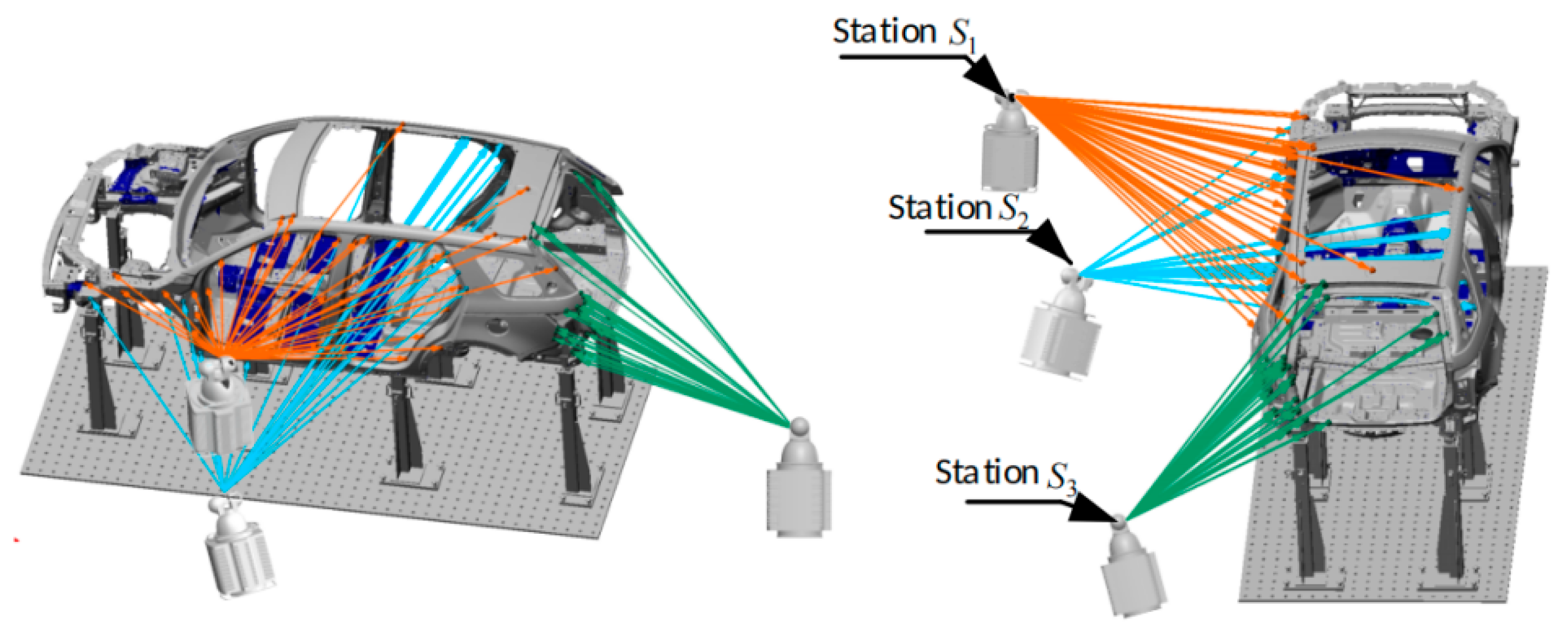
4. Experiments
5. Conclusions
Author Contributions
Funding
Institutional Review Board Statement
Informed Consent Statement
Data Availability Statement
Conflicts of Interest
References
- Fu, Y.K.; Yang, G.H.; Ma, H.J.; Chen, H.; Zhu, B. Statistical Diagnosis for Quality-Related Faults in BIW Assembly Process. IEEE Trans. Ind. Electron. 2023, 70, 898–906. [Google Scholar] [CrossRef]
- Kiraci, E.; Palit, A.; Donnelly, M.; Attridge, A.; Williams, M.A. Comparison of in-line and off-line measurement systems using a calibrated industry representative artefact for automotive dimensional inspection. Measurement 2020, 163, 108027. [Google Scholar] [CrossRef]
- Armagan, A.; Emre, B. Comparison of off-line laser scanning measurement capability with coordinate measuring machines. Measurement 2021, 168, 108228. [Google Scholar]
- Xi, Z.; Zhou, J.; Yang, B.; Zhang, Y.; Zhang, Z.; Li, D. An intelligent inspection method for BIW weld quality based on vibration excitation response signals. Measurement 2024, 229, 114482. [Google Scholar] [CrossRef]
- Li, H.; Li, B.; Liu, G.; Wen, X.; Wang, H.; Wang, X.; Zhang, S.; Zhai, Z.; Yang, W. A detection and configuration method for welding completeness in the automotive BIW panel based on digital twin. Sci. Rep. 2022, 12, 7929. [Google Scholar]
- Liu, W.; Jia, M.; Zhang, S.; Zhu, S.; Qi, J.; Hu, J. A Lightweight TA-YOLOv8 Method for the Spot Weld Surface Anomaly Detection of Body in White. Appl. Sci. 2025, 15, 2931. [Google Scholar] [CrossRef]
- Li, R.; Ma, L.; Tang, Q.; Sun, Y.; Su, B. Quality Inspection for the BIW Assembly of High-Speed Train Carriage Based on Machine Vision. IFAC-Pap. 2022, 55, 13–18. [Google Scholar]
- Yuan, Y.; Liu, Z.; Mu, H.; Liu, H. BIW Solder Joint Positioning Method Based on Machine Vision Technology. Procedia Comput. Sci. 2024, 243, 286–295. [Google Scholar] [CrossRef]
- Turley, G.A.; Kiraci, E.; Olifent, A.; Attridge, A.; Tiwari, M.K.; Williams, M.A. Evaluation of a multi-sensor horizontal dual arm Coordinate Measuring Machine for automotive dimensional inspection. Int. J. Adv. Manuf. Technol. 2014, 72, 1665–1675. [Google Scholar] [CrossRef]
- Sun, A.; Wang, J.; Qian, W.; Wang, L.; Fan, J.; Cao, T.; Gao, T.; Zou, Z.; Xu, L.; Ma, L.; et al. Development of a large-scale standard device for calibration of high-precision spherical coordinate scanning measurement systems. Precis. Eng. 2025, 94, 675–692. [Google Scholar] [CrossRef]
- Sanderson, D.; Turner, A.; Shires, E.; Chaplin, J.C.; Ratchev, S. Implementing Large-Scale Aerospace Assembly 4.0 Demonstration Systems. IFAC-Pap. 2020, 53, 10267–10274. [Google Scholar] [CrossRef]
- Jeremy, T.; Wang, Q.; Neil, B.; Roger, H. Offshore wind turbine blades measurement using Coherent Laser Radar. Measurement 2016, 79, 53–65. [Google Scholar]
- Wang, Q.; Zissler, N.; Holden, R. Evaluate error sources and uncertainty in large scale measurement systems. Robot. Comput.-Integr. Manuf. 2013, 29, 1–11. [Google Scholar] [CrossRef]
- Liu, W.; Qu, X.; Ouyang, J.; Wang, Z. Design and CAD-directed inspection planning of laser- guided measuring robot. Comput. Graph. 2008, 32, 617–623. [Google Scholar] [CrossRef]
- Larsson, S.; Kjellander, J. Path planning for laser scanning with an industrial robot. Robot. Auton. Syst. 2008, 56, 615–624. [Google Scholar] [CrossRef]
- Mahmud, M.; Joannic, D.; Roy, M.; Isheil, A.; Fontaine, J.F. 3D part inspection path planning of a laser scanner with control on the uncertainty. Comput.-Aided Des. 2011, 43, 345–355. [Google Scholar] [CrossRef]
- Wang, X.; Wang, J.; Xu, W.; Guo, D. Scanning path planning for laser bending of straight tube into curve tube. Opt. Laser Technol. 2014, 56, 43–51. [Google Scholar] [CrossRef]
- Zhang, C.; Kalasapudi, V.; Tang, P. Rapid data quality-oriented laser scan planning for dynamic construction environments. Adv. Eng. Inform. 2016, 30, 218–232. [Google Scholar] [CrossRef]
- Zhao, H.; Kruth, J.; Gestel, N.; Boeckmans, B.; Bleys, P. Automated dimensional inspection planning using the combination of laser scanner and tactile probe. Measurement 2016, 45, 1057–1066. [Google Scholar] [CrossRef]
- Lee, K.; Part, H. Automated inspection planning of free-form shape parts by laser scanning. Robot. Comput. Integr. Manuf. 2000, 16, 201–210. [Google Scholar] [CrossRef]
- Du, Z.; Wu, Z.; Yang, J. Point cloud uncertainty analysis for Laser Radar measurement system based on error ellipsoid model. Opt. Lasers Eng. 2016, 79, 78–84. [Google Scholar]


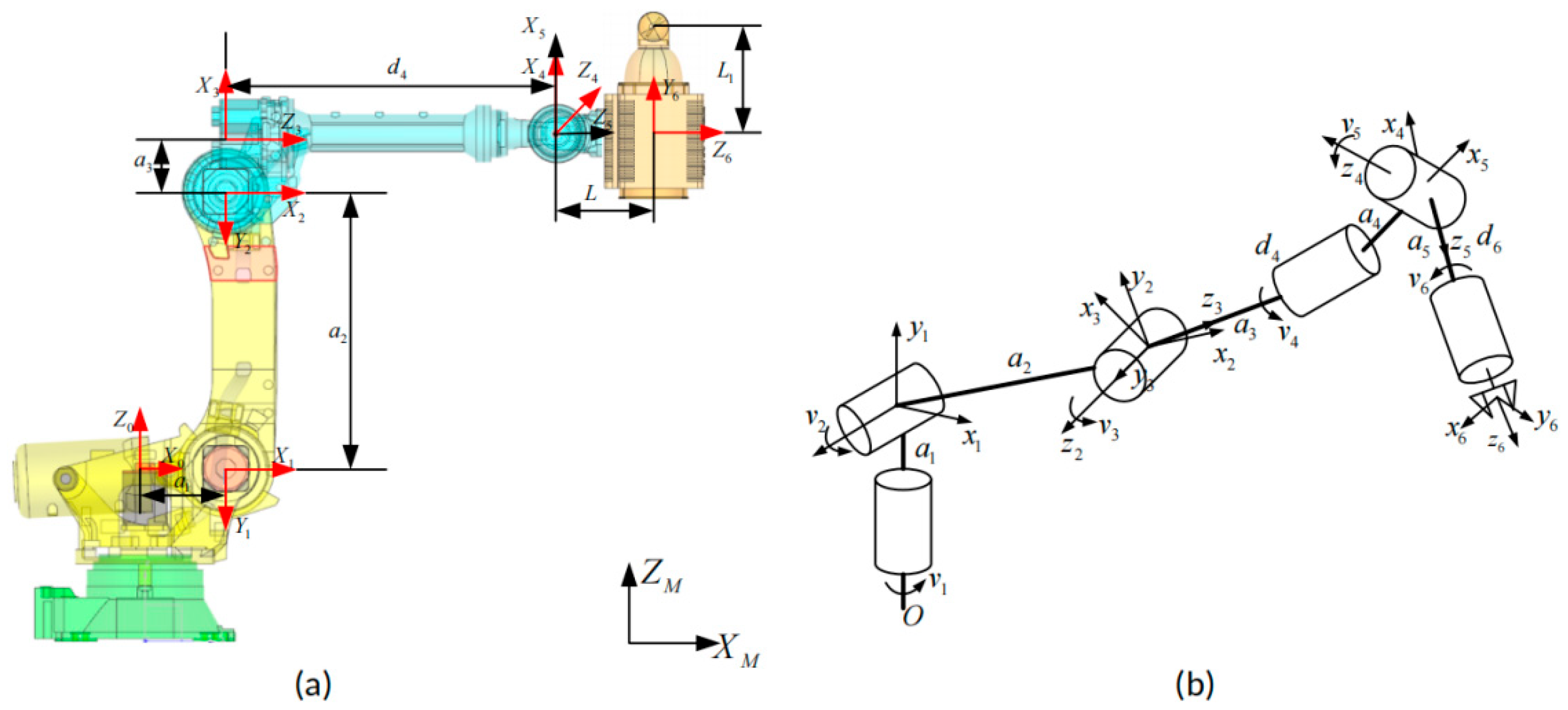
| No. | Distance Between Adjacent Axes (αi) | Angle Between Adjacent z Axes (αi) | Center Distance of Joint (di) | Angle Between Adjacent X Axes (βi) |
|---|---|---|---|---|
| 1 | α1 | −π/2 | 0 | β1 |
| 2 | α2 | 0 | 0 | β2 |
| 3 | α3 | −π/2 | 0 | β3 |
| 4 | α4 | −π/2 | d4 | β4 |
| 5 | α5 | −π/2 | 0 | β5 |
| 6 | α6 | 0 | L | β6 |
| Point Coding | x-Coordinate | y-Coordinate | z-Coordinate | Normal Vector i | Normal Vector j | Normal Vector k |
|---|---|---|---|---|---|---|
| L22A781CRE | 4233.000 | −626.621 | 1511.540 | 0.000 | 0.939 | −0.342 |
| R22A800ECE | 4881.610 | −850.327 | 873.572 | 0.399 | −0.328 | −0.856 |
| … | … | … | … | … | … | … |
| L22A413AFV | 4789.710 | −350.100 | 1681.750 | 0.090 | −0.070 | 0.990 |
| Region 1 | ||||||
|---|---|---|---|---|---|---|
| Point Coding | x-Coordinate | y-Coordinate | z-Coordinate | Normal Vector i | Normal Vector j | Normal Vector k |
| L22A818ASV | 4882.130 | −282.000 | 1602.000 | −0.780 | −0.030 | 0.632 |
| L12A800CSZ | 3856.000 | −567.000 | 1680.510 | 0.000 | −0.110 | 0.990 |
| … | … | … | … | … | … | … |
| L22A271AAZ | 3860.060 | −598.68 | 1703.400 | 0.000 | −0.220 | 0.970 |
| Region 2 | ||||||
| Point Coding | x-Coordinate | y-Coordinate | z-Coordinate | Normal Vector i | Normal Vector j | Normal Vector k |
| L22A771CRP | 3392.500 | 704.345 | 1212.290 | 0.000 | −0.995 | −0.100499 |
| R22A771ARP | 3295.200 | 705.737 | 1189.300 | 0.000 | −0.995 | −0.100 |
| … | … | … | … | … | … | … |
| L22A800ISY | 3705.500 | −762.500 | 480.000 | 0.000 | −1.000 | 0.000 |
| Region 3 | ||||||
| Point Coding | x-Coordinate | y-Coordinate | z-Coordinate | Normal Vector i | Normal Vector j | Normal Vector k |
| R22A781CRE | 4234.000 | 623.549 | 1519.990 | 0.000 | −0.940 | −0.340 |
| R22A781BCE | 4214.190 | 605.600 | 1560.620 | −0.037 | −0.933 | −0.358 |
| … | … | … | … | … | … | … |
| L12A801FSY | 1980.000 | −745.000 | 813.000 | 0.000 | −1.000 | 0.000 |
| No. | Distance Between Adjacent Axes (αi) | Angle Between Adjacent z Axes (αi) | Center Distance of Joint (di) | Angle Between Adjacent X Axes (βi) |
|---|---|---|---|---|
| 1 | 312 | −π/2 | 0 | β1 |
| 2 | 1075 | 0 | 0 | β2 |
| 3 | 225 | −π/2 | 0 | β3 |
| 4 | 0 | −π/2 | 1280 | β4 |
| 5 | 0 | −π/2 | 0 | β5 |
| 6 | 0 | 0 | 500 | β6 |
| Station Code | x-Coordinate | y-Coordinate | z-Coordinate | Normal Vector i |
|---|---|---|---|---|
| 1 | 4345.480 | −1450.000 | 3189.060 | 0.000 |
| 2 | 2951.560 | −2754.620 | 2111.580 | 0.000 |
| … | … | … | … | … |
| 45 | 2373.710 | −1503.180 | 3045.900 | 0.549 |
Disclaimer/Publisher’s Note: The statements, opinions and data contained in all publications are solely those of the individual author(s) and contributor(s) and not of MDPI and/or the editor(s). MDPI and/or the editor(s) disclaim responsibility for any injury to people or property resulting from any ideas, methods, instructions or products referred to in the content. |
© 2025 by the authors. Licensee MDPI, Basel, Switzerland. This article is an open access article distributed under the terms and conditions of the Creative Commons Attribution (CC BY) license (https://creativecommons.org/licenses/by/4.0/).
Share and Cite
Li, L.; Wang, S.; Ma, J.; Gao, X. Research on Laser Radar Inspection Station Planning of Vehicle Body-In-White (BIW) with Complex Constraints. Appl. Sci. 2025, 15, 6181. https://doi.org/10.3390/app15116181
Li L, Wang S, Ma J, Gao X. Research on Laser Radar Inspection Station Planning of Vehicle Body-In-White (BIW) with Complex Constraints. Applied Sciences. 2025; 15(11):6181. https://doi.org/10.3390/app15116181
Chicago/Turabian StyleLi, Lijuan, Siyi Wang, Jichao Ma, and Xiaobing Gao. 2025. "Research on Laser Radar Inspection Station Planning of Vehicle Body-In-White (BIW) with Complex Constraints" Applied Sciences 15, no. 11: 6181. https://doi.org/10.3390/app15116181
APA StyleLi, L., Wang, S., Ma, J., & Gao, X. (2025). Research on Laser Radar Inspection Station Planning of Vehicle Body-In-White (BIW) with Complex Constraints. Applied Sciences, 15(11), 6181. https://doi.org/10.3390/app15116181