Article

Control and Real-Time Monitoring of Autonomous Underwater Vehicle Through Underwater Wireless Optical Communication

1
Department of Mechanical Engineering, Korea Maritime & Ocean University, Busan 49112, Republic of Korea
2
Sea Power Reinforcement & Security Research Department, Korea Institute of Ocean Science and Technology, Busan 49112, Republic of Korea
3
FAE & Research Department, ZeyGi, Suwon-si 16229, Republic of Korea
*
Authors to whom correspondence should be addressed.
Appl. Sci. 2025, 15(11), 5910; https://doi.org/10.3390/app15115910 (registering DOI)
Submission received: 10 April 2025 / Revised: 21 May 2025 / Accepted: 22 May 2025 / Published: 24 May 2025

Abstract

:
Real-time command and data transfer are essential for autonomous underwater vehicle (AUV) motion control in underwater missions. Due to the limitations of underwater acoustic communication, which has a low data rate, this paper introduces a new control structure using underwater wireless optical communication (UWOC) to enable effective real-time command and data transfer. In this control structure, control inputs for the AUV attitude from outside of the water are transferred to the AUV for motion control, while its orientation data and visual images from the AUV camera are sent to the control station outside the water via the UWOC system. For demonstrating the performance of control action and data monitoring, an AUV is built with a constructed UWOC system, two vertical thrusters, and two horizontal thrusters. For attitude control of the AUV, an attitude heading reference system (AHRS) and a depth sensor are installed. Bi-directional communication in the UWOC system is achieved using a return-to-zero (RZ) modulation scheme for faster, longer-range data transfer. A signal processor converts sensor data received from the transmitted data. Finally, the hovering control performance of the AUV equipped with the UWOC system was experimentally evaluated in a water tank, achieving average root mean square errors (RMSEs) of 4.82° in roll, 2.49° in pitch, and 1.99 mm in depth, while simultaneously transmitting real-time motion data at 21.2 FPS with VGA-resolution images (640 × 480 pixels) at a communication rate of 1 Mbps.

1. Introduction

Electromagnetic waves in the MHz band or higher experience significant attenuation underwater due to the conductivity of water, and the attenuation rate generally increases with frequency under identical environmental conditions [1,2]. As a result, electromagnetic wave-based communication commercially available overland cannot be applied under the water, and acoustic waves with water as a medium or visible light from a light source are instead used for underwater wireless communication [3]. Acoustic wave communication provides a long communication distance but is limited in high-speed communication since the amount of data transmission is small [4]. Underwater wireless optical communication (UWOC) provides a shorter communication distance than acoustic wave communication but allows high-speed communication [5]. Despite signal attenuation and delay caused by variations in salinity, temperature, and bubble presence and by light scattering and absorption, UWOC delivers propagation speeds higher than underwater acoustic communication [6].
Unmanned underwater vehicles (UUVs) are one of the important applications of underwater communication. Underwater communication is essential for sending scan information obtained underwater or the condition of the UUV to other UUVs or to the ground. Also, high-speed communication is required to process underwater images for real-time inspection of marine structures or piers in port facilities [7]. So far, cables have been used for the communication of UUVs such as remotely operated vehicles (ROVs). These cables can break or bend with structures, reefs, rocks, and floating objects, causing damage to the ROVs or restricting their activity [8,9]. Therefore, high-speed wireless communication without cables is necessary to achieve the smooth operation of ROVs.
Underwater acoustic communication has been commonly used so far for underwater communication but is unsuitable as a real-time video communication medium due to the low data rate of 100–5000 bps. To solve the delayed data rate of underwater acoustic communication, numerous studies on UWOC technology have been performed [7]. In the literature, a detailed overview of various research activities on UWOC was presented [10]. Extensive research was carried out to develop complementary technology, which can allow broadband underwater communications such as real-time video transmissions, teleoperation of autonomous underwater vehicles (AUVs), and remote monitoring of underwater stations [11]. Also, in a recent study on practical research, researchers provided a review of practical considerations and solutions in UWOCs. However, most of these studies focus on increasing the underwater optical wireless communication speed and its verification in an indoor water tank [12].
There were some studies on UWOC between AUVs and underwater modems or AUVs and the surface vehicle. In 2023, Han et al. demonstrated a UWOC system that achieved a communication distance exceeding 35 m at a data rate of 1.9 Mbps [13]. By Anguita et al., a cooperative control framework based on potential field theory and a hybrid (optical/acoustic) data transfer policy based on Saaty’s analytic hierarchy process (AHP) algorithm was studied [14]. However, in this paper, the validity of the proposed algorithm was presented through simulation instead of experiments. A compact, low power consumption, cost-efficient, and lightweight optical modem designed for fast data transmission between MEDUSA at ranges on the order of 10 m was presented [15]. The experiments have shown the capability of the modem to transmit data at 20 kb/s, over a distance of 10 m in water with 4–5 m visibility.
A bi-directional UWOC system, the Woods Hole Oceanographic Institution (WHOI) optical modem, was deployed on a seafloor test node and on the AUV Sentry. A complete optical field map of the signal from the seafloor node was generated with an autonomous data mule mission. A test data transfer was made between the node and Sentry over the wireless optical modem from a 20 to 150 m slant range at data rates of 5 and 10 Mbps [16]. The WHOI optical modem was deployed on a seafloor Ocean Bottom Seismometer and on a REMUS 600 AUV. Test data were successfully transferred from the Ocean Bottom Seismometer to REMUS over the wireless optical modem at a ~30 m slant range at data rates of 5–10 Mbps [17]. A study was performed on the docking of AUVs to a docking station using light and a light sensor system under the water. For this, a guiding system for an AUV loading sensor system composed of a lens, light sensor, signal processor, and control processor and a docking system with LED was proposed [18]. However, there is currently no research on AUV motion control that integrates real-time image transmission via UWOC between the underwater vehicle and an above-surface communication modem.
In this study, a new control structure for the AUV motion based on real-time commands using the UWOC system is proposed. In this control structure, control inputs for the AUV attitude from outside of the water are transferred to the AUV for motion control, while its orientation data and motion images from the AUV camera are sent to the control station outside of the water via the UWOC system.
For two-way communication between the ground and the AUV, a light receiver using an LED transmitter and a PIN photodiode was designed and installed in the AUV. In addition, four thrusters were installed on the AUV to control the water depth and attitude. The attitude control of the AUV based on the developed UWOC system was verified through underwater experiments.

2. AUV Design and Construction
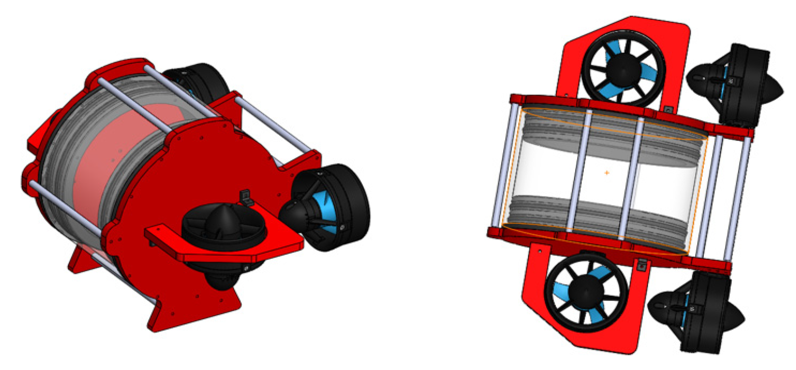
2.1. AUV Structure

In this study, an AUV equipped with an underwater optical wireless communication system was produced to implement AUV communication using the underwater optical wireless system and the hovering control of the AUV based on the UWOC. The hull of the AUV consisted of a transparent acrylic housing to ensure visibility for the camera and underwater light communication, and the control electric field and battery were secured inside with a PLA bracket. Designed in the shape of a fish, the AUV consisted of four thrusters, acrylic end caps for internal waterproofing, aluminum flanges, frame bars, connectors, a buoyancy system for neutral buoyancy, weight, and a power switch. Figure 1 shows the images of the produced AUV, and Table 1 shows the specifications of the instrument. Figure 2 shows the structure of the produced AUV. The AUV system is divided into an AUV frame, control system, UWOC system, and operating PC with four degrees of freedom. The AUV is equipped with a UWOC system to transmit and receive data at high speed with underwater or out-of-water optical communication systems. The UWOC system was composed of LEDs, and a graphical user interface (GUI) was built by connecting the operating PC to an external optical communication system to obtain data for AUV operation and sensors as well as image information.

2.2. System Configuration and Dynamics

The constructed AUV is equipped with four thrusters, T s 1 , T s 2 , T r 1 , and T r 2 , where T r 1 and T r 2 are for surge and yaw thrusting, and T s 1 and T s 2 are for heaving and pitching, as shown in Figure 3. T s 1 and T s 2 are allocated at the side of the AUV by l r along the Y-axis and by l p along the X-axis. T r 1 and T r 2 are allocated at the side of the AUV by l y along the Y-axis.
In this paper, to control the heave, pitch, roll, and yaw motion of the AUV, the vector and moment expression of the dynamics of the AUV are expressed as follows [19]:
M v   ˙ + C v v + G η = τ
where
F z K M N =   0 0 1 1 0 0 l r 1 l r 2 0 0 l p 1 l p 2 l y 1 l y 2 0 0 T s 1 T s 2 T r 1 T r 2
In Equation (1), M is the inertia matrix, C v represents the Coriolis and centripetal force matrix, G η is the restoring force and moment vector due to gravity and buoyancy, and τ is the vector of external forces and moments. Also, F z represents the vertical force, and K , M , and N correspond to the roll, pitch, and yaw moments, respectively.
Based on the allocation of the thrusters, the related configuration matrix between the input torque, τ , and thrusting forces is expressed as
τ = B u
where
B = 0 0 1 1 0 0 l r 1 l r 2 0 0 l p 1 l p 2 l y 1 l y 2 0 0 ,   τ = F z K M N T ,   u =   T s 1 T s 2 T r 1 T r 2 T
The AUV is experimented with in the calm water tank, and it is slow in heave motion and roll, pitch, and yaw rotations, such that the added mass and moment of inertia can be neglected. Also, the AUV is designed to be symmetrical with respect to the xy and yz planes, it has no sway direction thrusters, and its center of mass is centered on the AUV axis. Hence, the dynamics of the AUV in the hovering state are expressed with the same expression as [19]:
m w ˙ u q =   F z I x x p ˙ + I z z I y y qr   = K I y y q ˙ + I x x I z z rp   = M I z z r ˙ + I y y I x x pq   = N

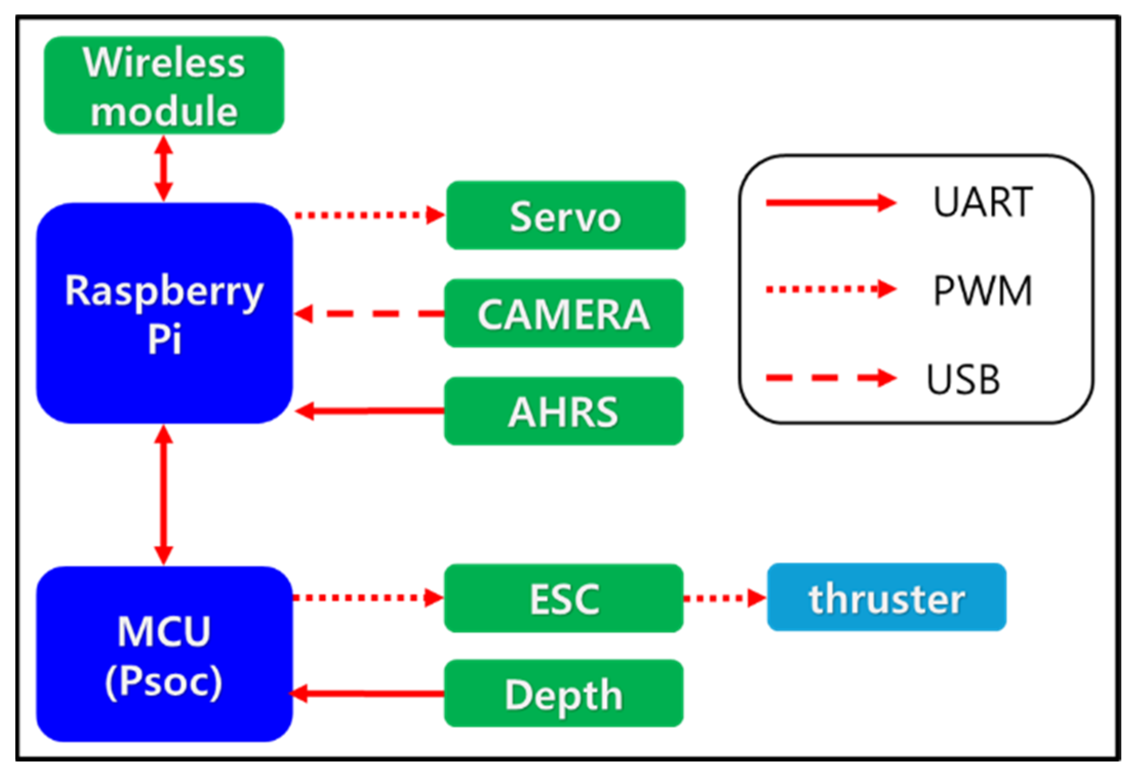
2.3. Control System and Sensors

Figure 4 illustrates the structure of the control system of the AUV. The microprocess computing unit (MCU) composed of Psoc inside the AUV receives data from a Raspberry Pi (RPI) and sends pulse-width modulation (PWM) signals to the servomotor. The MCU also receives data from the depth sensor and the attitude heading reference system (AHRS) sensor, which measures the attitude of the AUV, and transmits them to the RPI. The RPI collects the camera image and sensor data received from the MCU and displays the collected sensor data on the screen through the GUI. The control of the AUV is transmitted through the UWOC system according to an external command. The GUI screen was built such that the camera image, sensor data, and communication status could be confirmed, and CRC32 was applied to check the communication data. Figure 5 shows the GUI screen, which shows the orientation and position of the AUV with the visual information of the underwater camera on the AUV.
The sensors used for attitude control of the AUV include the AHRS and depth sensors. Adafruit’s BNO055 model was used for the AHRS, which provides roll, pitch, and yaw values.

2.4. Altitude Control Algorithm

AHRS and depth sensor information inside the AUV is used to maintain the AUV in the desired position and orientation. The AHRS supports the hovering mode through the roll, pitch, and yaw values, and the depth sensor allows the target depth to be stably maintained based on the depth value. A practical PID control is applied to maintain the hovering mode and water depth, and the error equation used for the control is as follows:
e = v d v
Equation (4) shows the error equation for attitude control, and e is the attitude error vector for the AUV. v d is the desired input vector for the roll, pitch, and yaw, and v is the output vector for the roll, pitch, and yaw of the AUV’s AHRS. The PID control signal based on the error signal is expressed in Equation (5), and the gain value of each PID controller, K P , K i , and K D , are experimentally determined by tunning.
U t = K P e t + K i 0 t e t d t + K D d e t d t

3. Underwater Wireless Optical Communication System

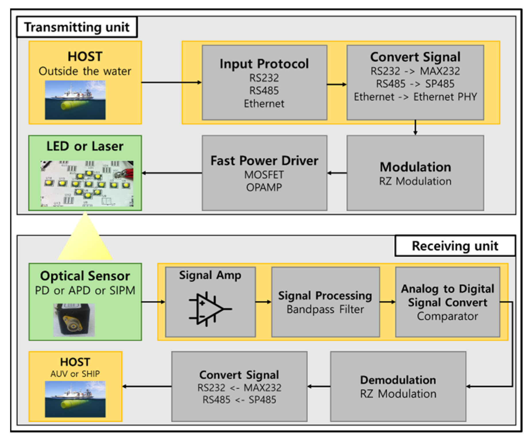
3.1. Structure of UWOC

Figure 6 shows the structure of the UWOC system between the AUV and the optical modem outside the water. Although the UWOC system includes both a transmitting and receiving unit and supports bi-directional communication, Figure 6 presents these units separately to clarify the distinct processes of sending and receiving.
The transmitter on the AUV sends data in protocol signals, such as UART, RS232, and Ethernet. To reduce the noise of the corresponding signal data, the return-to-zero (RZ) modulation technique is used [20,21]. In short-range scenarios, RZ modulation exhibits higher receiver sensitivity than non-return-to-zero (NRZ) modulation [22]. In this paper, RZ modulation was adopted since UWOC was used to remotely control an AUV at distances within a few meters. Modulated data are amplified by the power amplifier and transmitted through the LED. On the receiving side, a current is generated by detecting the LED light with the photodiode, and the corresponding current is signal processed to transmit data to the host.

3.2. LED Light Attenuation with Communication Distance

When the distance between the LED transmitter and receiver reaches d , the LED attenuation and communication noise may be considered in terms of the additive white Gaussian noise (AWGN). Also, the intensity of the light emitted by the LED may be referred to as I λ , and the attenuated intensity of the corresponding light, d I λ , at the underwater distance, d , can be described using Beer’s law, as shown in Equation (6) below [23].
d I λ = c λ I λ d z
By integrating the above equation, the intensity of light with respect to the distance, d , can be expressed as shown in Equation (7).
I λ = I 0 λ e c λ d
The variables for the corresponding equation are as follows:
d : communication distance;
I λ : intensity of light reaching the receiver;
I 0 λ : initial intensity of light emitted by the LED, etc.;
c λ : attenuation coefficient obtained underwater.
Table 2 shows the absorption and scattering coefficients calculated at the wavelength of 514 nm.
In UWOC, the intensity of light detected by the receiver is inversely proportional to the square of the receiving distance and is inversely proportional to the gain of the receiver sensor. The intensity of light detected by the receiver, P r , can be expressed as shown in Equation (8) [23].
P r = P o A r 4 π d 2 e c λ d
As the variables for this equation, P o is the light intensity of the LED, etc., A r is the area of the receiver, and d is the distance between the LED and the receiver. Therefore, when the underwater attenuation coefficient is high, the intensity of light detected by the receiver is exponentially reduced.
Modifying Equation (8) yields
ln A =   ln ( 1 d 2 e c d )
where A = P r P 0 · 4 π A r .
Equation (9) can be arranged to relate the damping coefficient equation, c , with the distance, d , as follows:
c = 1 d ln A + 2 ln d
The researchable communication distance of the UWOC and damping coefficient c are exponentially related to turbidity, and the turbidity is related to the damping coefficient. Finding the communication distance of the UWOC is important. For this, after finding the damping coefficient, as the derived Equation (10), the communication distance can be estimated by measuring the intensity of the received light and the sensor area. The intensity of emitting light and the area of the receiving light can be designed for a better researchable communication distance of the UWCOM.

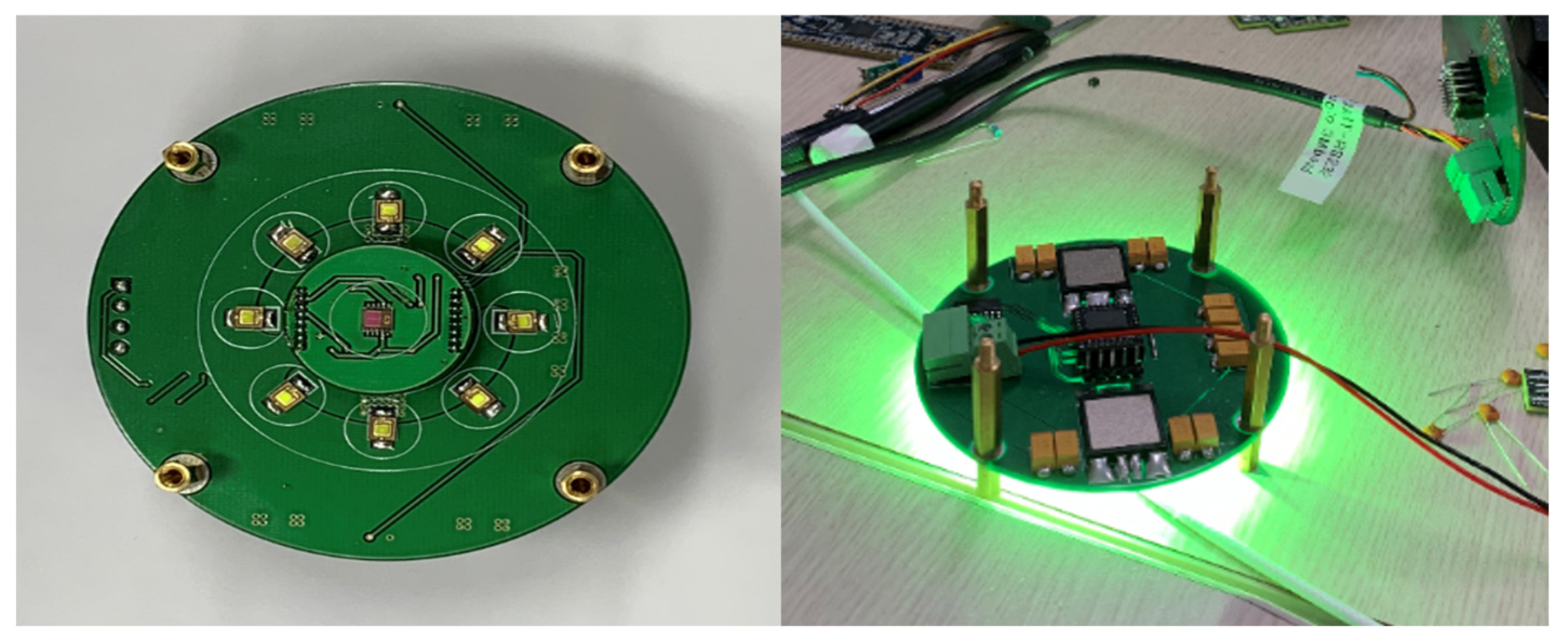
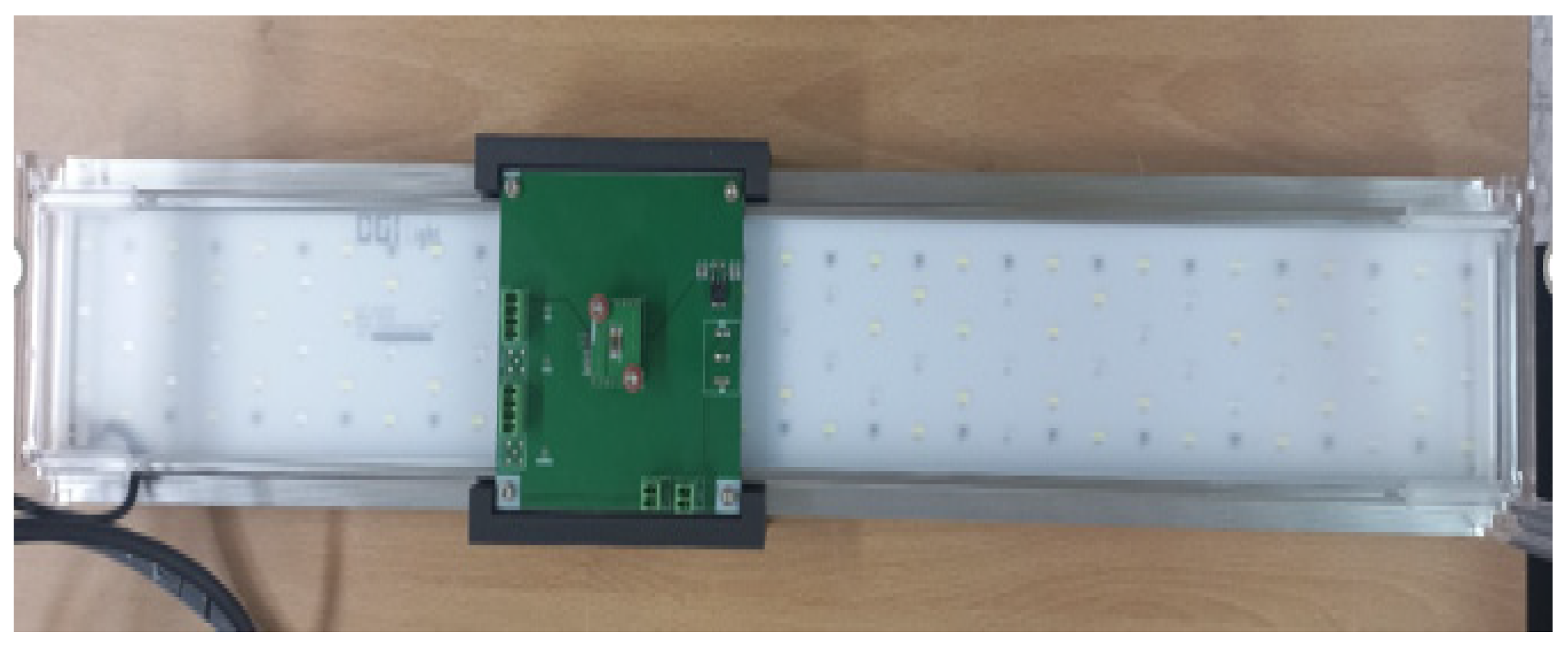
3.3. Hardware Design of Optical Communications System

In general, LEDs have shorter communication distances than laser diodes, but they consume less power and are more reliable [24], making them ideal for real-time short-range communication in UUVs. In this study, LED was used as an optical communication transmission light source and installed in a planar arrangement based on the horizontal operation of the AUV. Additionally, a green LED chip with a high transmittance in the 520 nm wavelength band was used to allow visible light to reach deep water [25]. Table 3 shows the specifications of LEDs used in the AUV.
Figure 7 shows the developed PCB with LEDs mounted on the AUV’s UWOC system. The UWOC system functions to transmit the AUV’s real-time camera and attitude data and to receive commands from the operator. The LED chip for projection was mounted to reduce the size, and eight LEDs were arranged in a circular form to increase the output power. In the UWOC system, a light-receiving sensor was placed in the board center to enable two-way communication, and a driver and MCU for high-power on/off keying (OOK) and size reduction were mounted on the back of the transmission board to control the LEDs. The LED driver was designed to provide a stable current supply using a chip with a continuous 2A, pulsed 30A push–pull drive structure.
Figure 8 shows the UWOC system developed for above-surface deployment. This system is integrated into the ground control system (GCS) to relay the operator’s commands to the AUV and to receive and transmit signals from the AUV back to the operator. To extend the AUV’s operational range, the optical transceiver is coupled with a widely distributed array of high-power, wide-angle LEDs. This configuration enables reliable two-way optical communication across a large area.

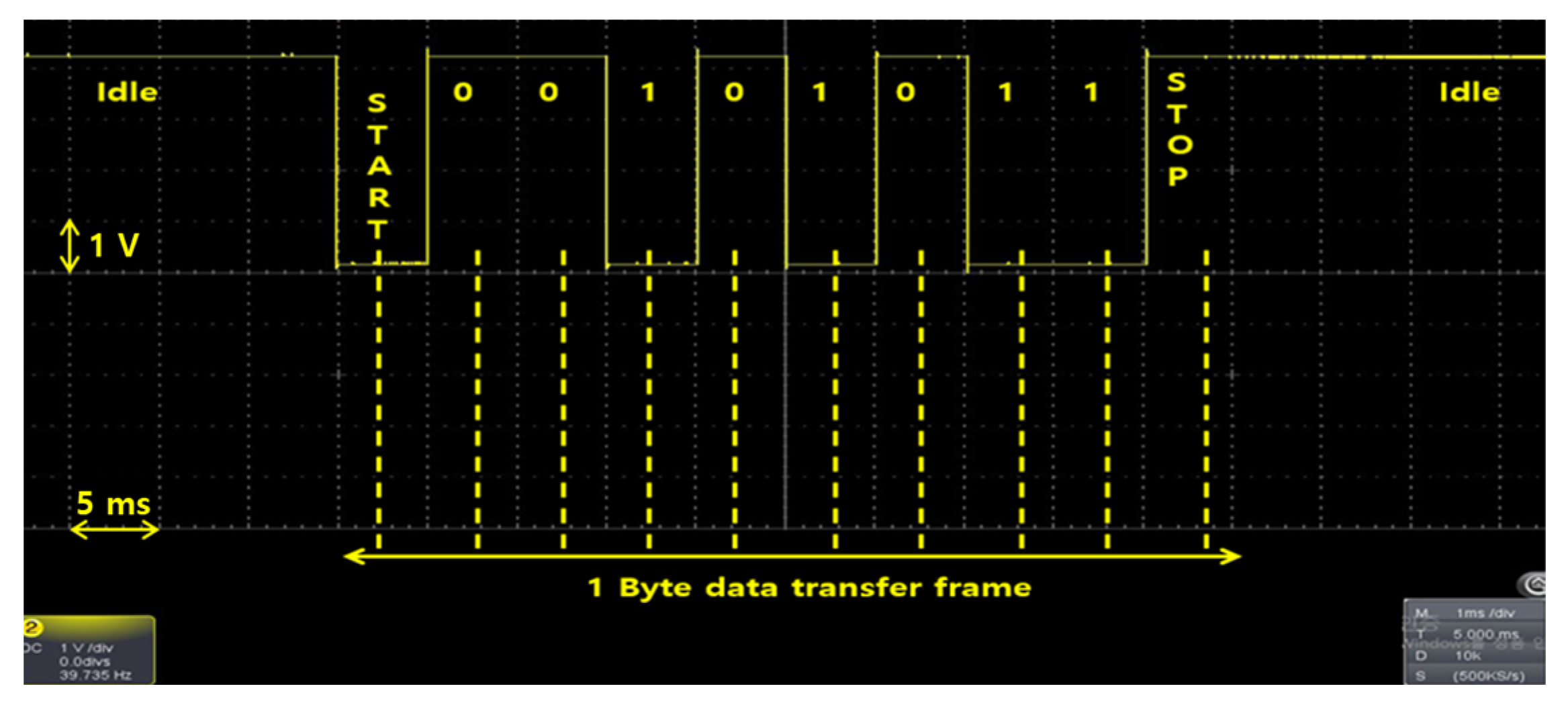
3.4. UWOC Light Modulation Technique

Figure 9 shows a UWOC environment in which noise occurs during data communication due to several factors, such as ambient light, sunlight, the turbidity of the water, and scattering and absorption of light [26]. Since noise distorts signals, the receiver uses a low-pass filter (LPF) to remove noises after receiving the signal.
However, because the LPF also distorts the original signal, a modulation-based restoration process is required. Figure 10 shows the state of the ideally received data signal. Passing the signal through the LPF filter without modulation results in a waveform that does not clearly exhibit the high signal and low signal, as seen in Figure 11, which increases the error rate during data communication. Therefore, the data signal must be modulated before being passed through the filter using modulation techniques such as OOK and RZ.
Figure 12 shows the waveform of the data signal passed through the LPF using the RZ modulation method. In the RZ modulation method, the received high signal is maintained and immediately returned to the low signal. The low signal is then maintained for a certain period between bit pulses before being transmitted to the next signal. The RZ modulation method allows high-speed communication of visible light underwater and reduces the signal error rate since it requires a smaller bandwidth than the OOK modulation method and uses high-output light to transmit light far underwater or a photodiode sensor that detects weak light with a lower bandwidth [27]. Figure 13 presents a comparison of the real data before and after the application of RZ modulation. The magnitude of the received data (Rx Data) nearly doubles after applying RZ modulation, significantly enhancing signal clarity and making it distinctly separable from noise.

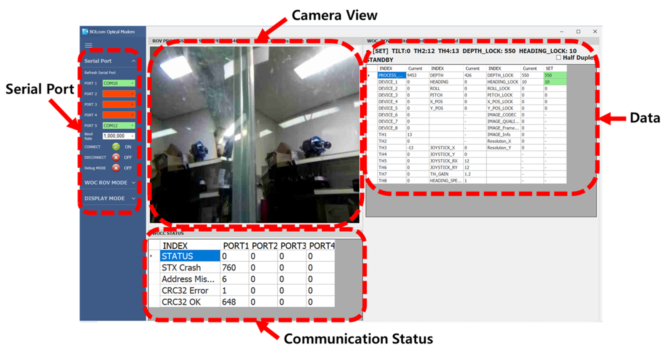
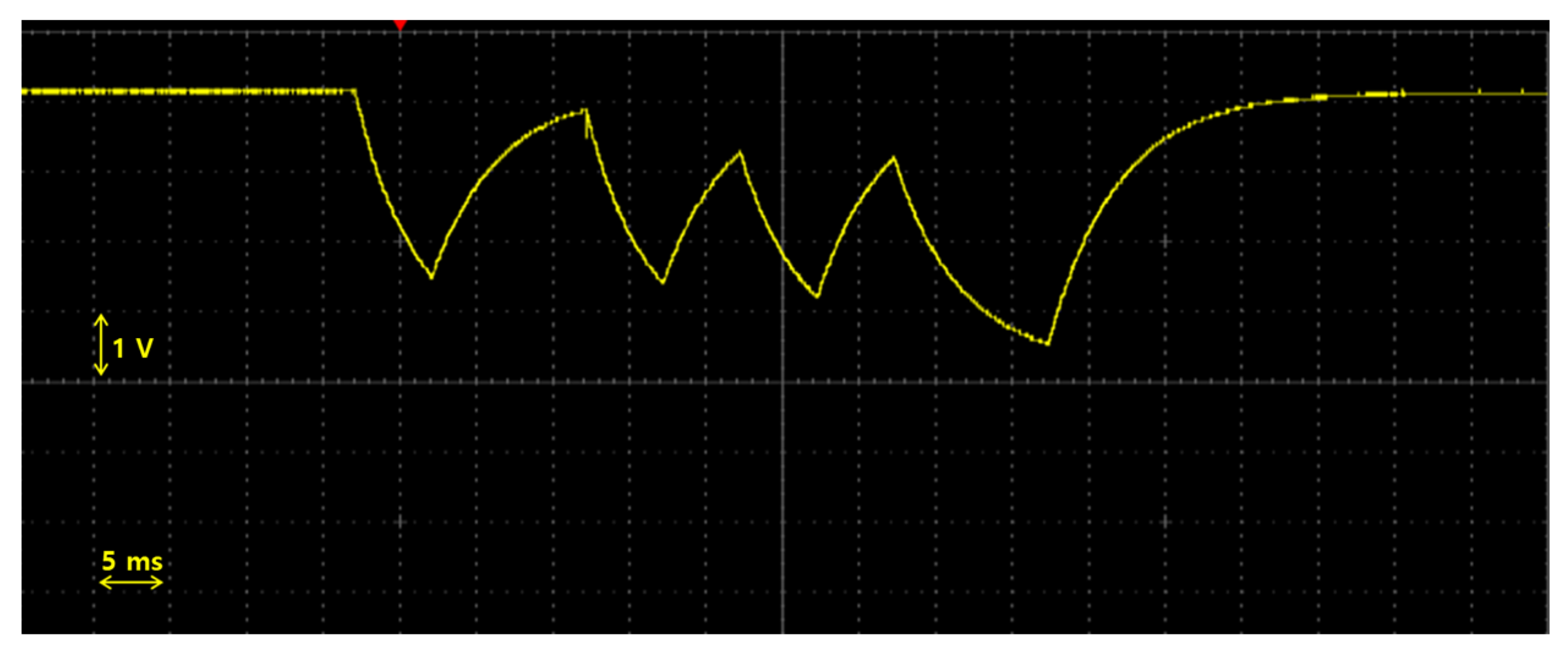
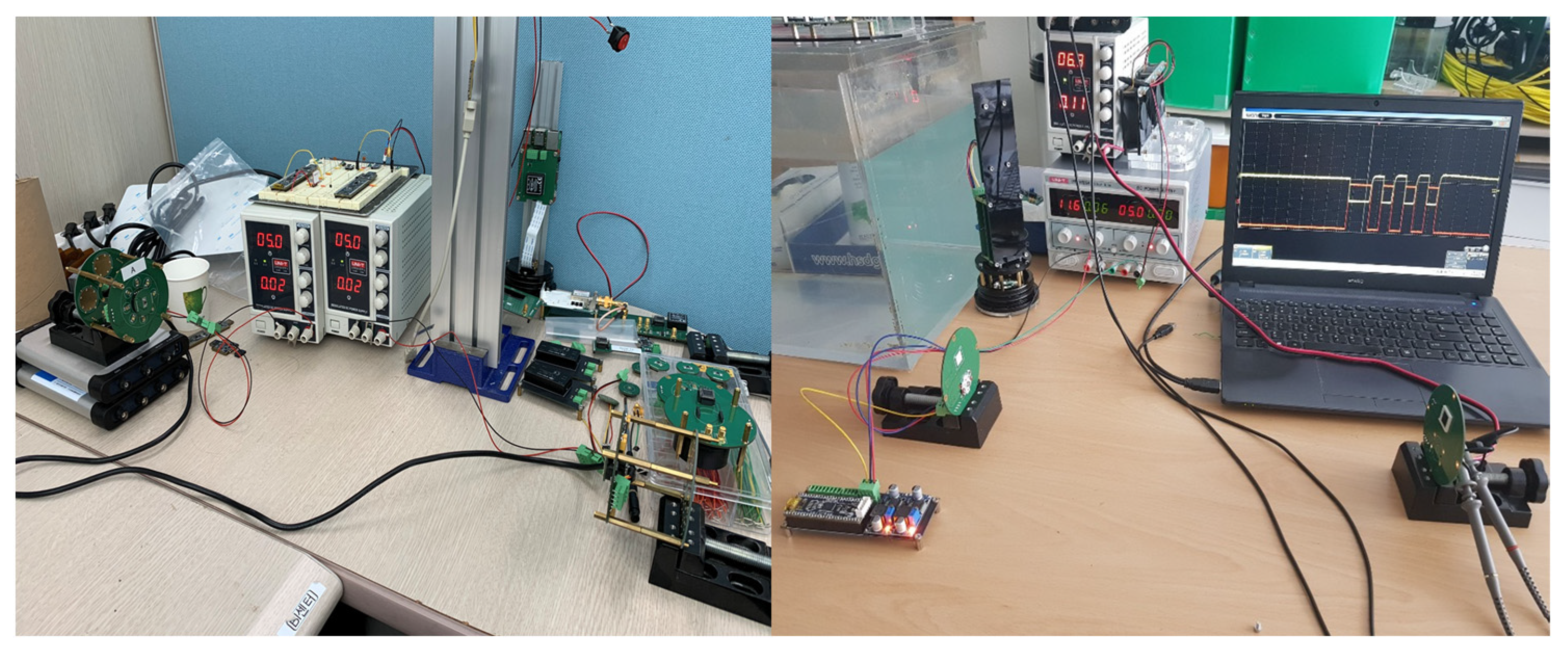
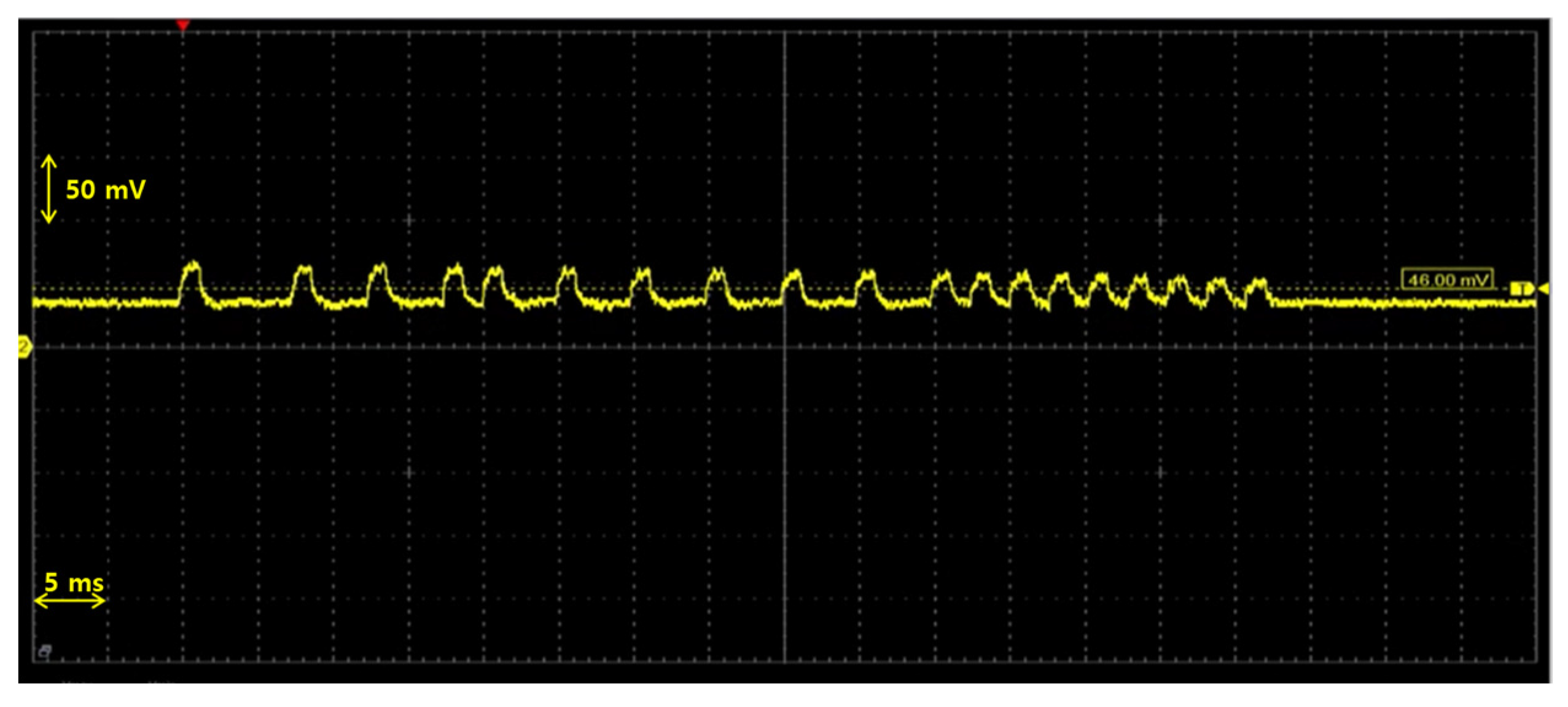
3.5. Performance Test of UWOC System

Figure 14 shows the communication test process of the UWOC system for circuit design verification. A communication test was conducted under the conditions of daylight at a distance of 1 m in the air and ambient light from office LEDs, and the visible light system was found to consume 0.02 A of power when on standby for reception. For maximum power consumption, since the light was emitted every time bit 0 was transmitted, approximately 2.2 A of power was consumed when 0 × 00 was continuously transmitted. When the data were typed for transmission using a terminal program, the text was received normally without any break.
The PIN diode attached to the light receiver of the UWOC system is sensitive to light and vulnerable to ambient light and dimmed light, leading to increased noise and communication error rates. Also, as the communication distance increases, the LED output detected by the light receiver decreases, and the waveform also becomes ambiguous between the high and low signals. The two cases are shown as simple tests. Figure 15 shows the voltage signal detected by the light receiver in a waveform when the distance between the transmitter and the light receiver is at a communication distance of 1 m, and Figure 16 illustrates the waveform of the signal detected at a communication distance of 2.5 m such that differences between the high and low signals are reduced.

4. Attitude Control Experiments

4.1. UWOC Experiments

An experiment was conducted in a water tank to verify the performance of the AUV using the developed UWOC system. The turbidity of the water tank was measured using Valeport’s HYPERION Turbidity sensor, and the average turbidity value was 0.267 Nephelometric turbidity units (NTUs). Since water with turbidity below 1 NTU is considered exceptionally clear and potable [28], the absorption and scattering coefficients for the water tank are assumed to correspond to those of pure seawater, as detailed in Table 2. Figure 17 shows the ground installation of the optical communication system, which is placed 800 mm away from the water surface. The experiment was performed on the communication speed, communication range, and the communication error rate of the AUV depending on the ambient light, and the attitude of the AUV was controlled by transmitting the control command through wireless communication.

4.2. Communication Speed Experiment

The underwater optical communication speed between the AUV and the ground was set to a maximum of 1 Mbps in the operation program and was found to be satisfactory. Camera image information in the AUV could be checked in real-time by setting the resolution at VGA (640 × 480) with the frames per second (FPS) at 20. The change in the camera FPS could be examined with the presence and absence of indoor fluorescent lights and dimming. The camera FPS increased to a maximum of 21.2 FPS, and the camera image was streamed without any interruption. Figure 18 shows the total number of received data packets matches the count of CRC-verified packets, indicating successful data integrity verification.

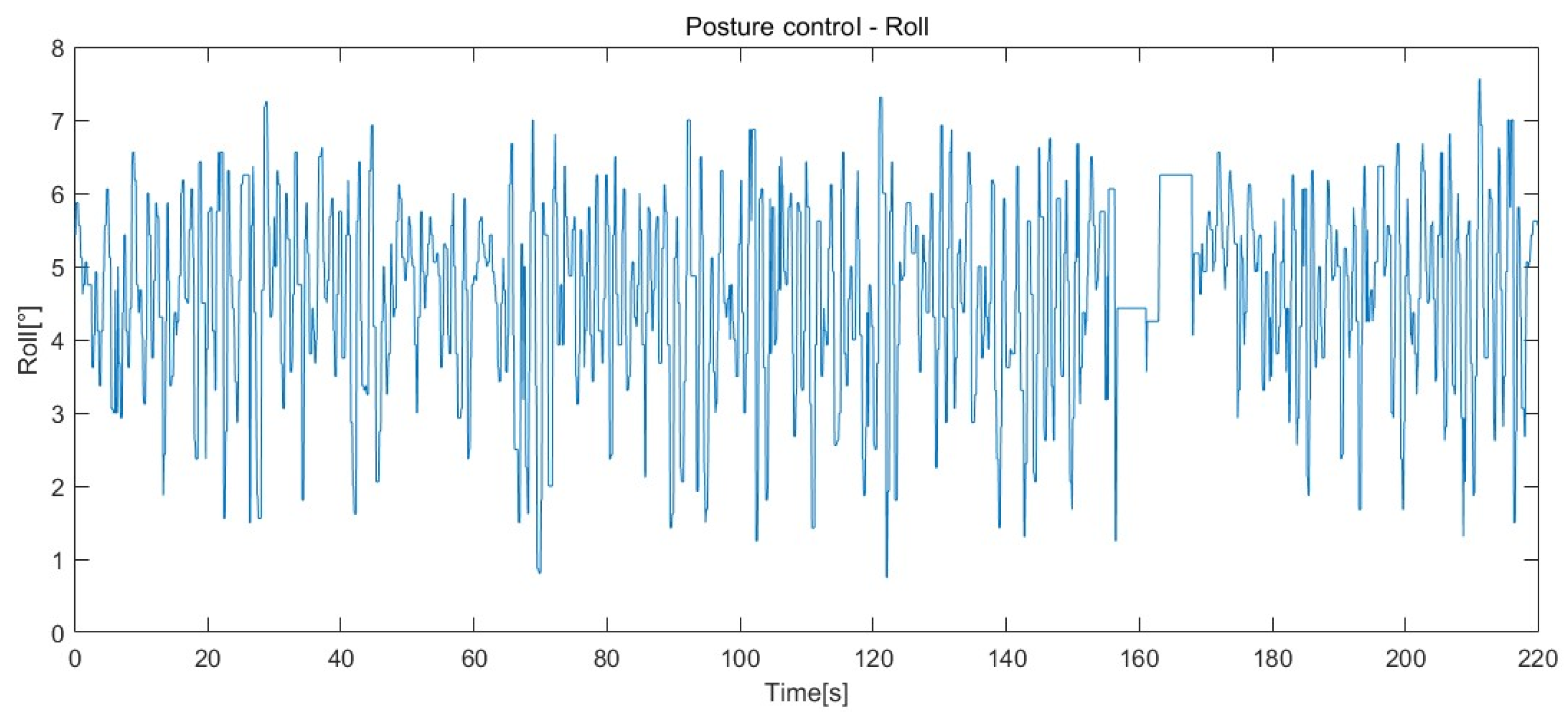
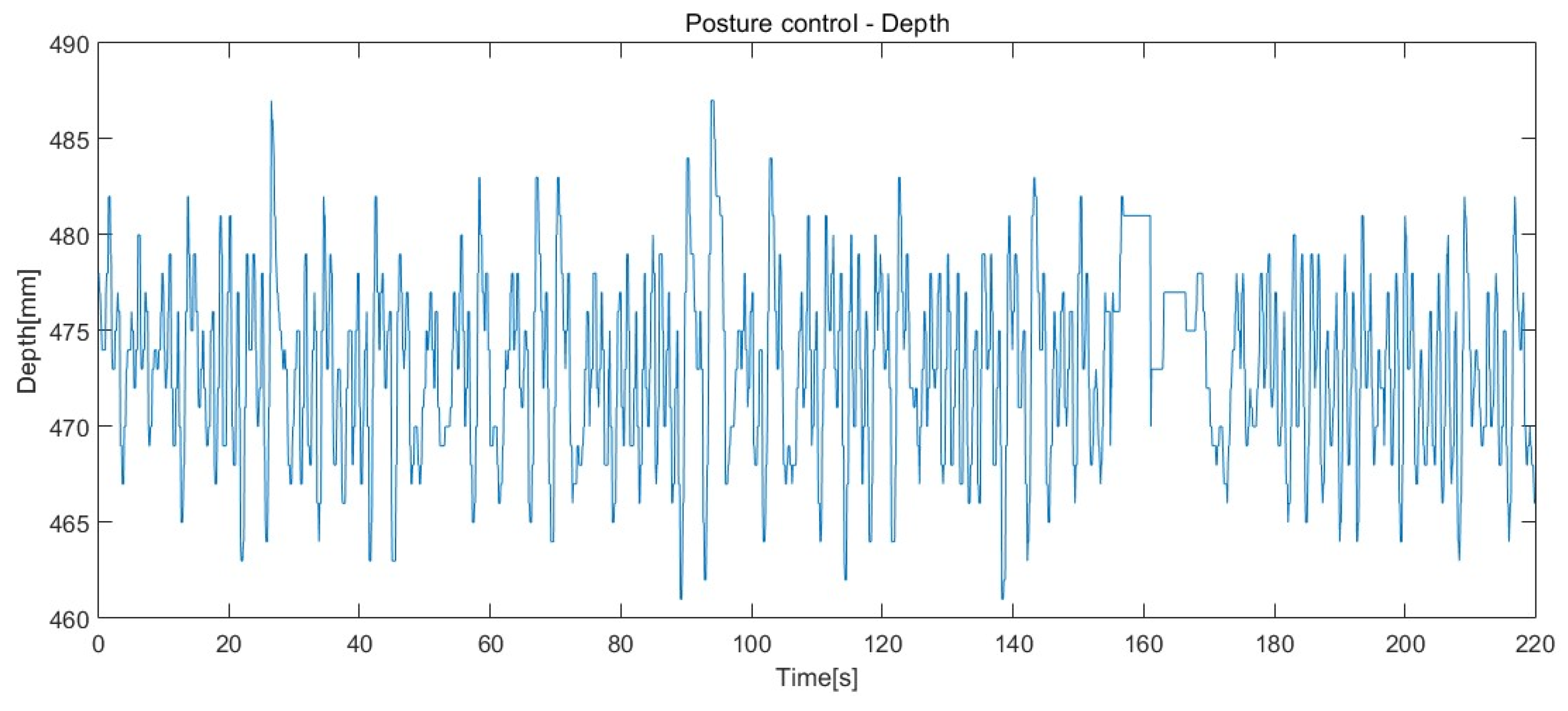
4.3. Posture Control Experiment

The posture control experiment was conducted in an experimental water tank, shown in Figure 17. The AUV’s states (roll, pitch, yaw, and depth) were transmitted through the underwater visible light system with a communication speed of 1 Mbps and a loop time of 0.01 s. The sensor output data were stored every 0.1 s. Table 4 shows the experimental results. Figure 19, Figure 20 and Figure 21 show the respective attitude and depth sensor data graphs in the order of roll, pitch, and depth. Yaw data were not recorded because the AUV was rotated to obtain camera footage from multiple directions.
The results of the control experiment in Table 4 show the mean error values for attitude control by receiving the attitude information of the AUV through underwater optical communication. In the experiment, it was not easy to control the roll and pitch attitude since the AUV was small and light, but the roll and pitch were effectively controlled within 5° and 2.5° in real-time, respectively, demonstrating stability even under external disturbances such as minor water currents and thruster-induced vibrations. Particularly, the error in depth was less than 2 mm even at the shallow depth of the water tank, indicating an effective control. Ultimately, this experiment demonstrated that it was possible to monitor images of the AUV from the ground in real time through optical wireless communication and to control the attitude of the AUV in real time based on the attitude control command. Overall, the consistent stability observed across all three parameters emphasizes the robustness of the developed hovering control system and the practical applicability of UWOC-based real-time control.
Also, while the AUV is under motion control, the video images from the AUV can be transferred through the developed UWOC system. To visually verify the image changes, a photo simulating the underwater environment was attached to the wall of the tank and filmed by the AUV. While controlling the AUV, the video data from the underwater image with 1 Mbps equivalent to 21.2 FPS with VGA (640 × 480) resolution and the roll and yaw motion data of the AUV were successfully transferred to the over-water control station. Two captured motion pictures from the real-time video images of the AUV in the water tank with 1 Mbps are presented in Figure 22.

5. Conclusions

In this paper, a new control structure for the AUV motion based on real-time commands using the developed UWOC system is studied. In this control structure, control inputs for the AUV attitude from outside of the water are transferred to the AUV for motion control, while its posture data and video images from the AUV camera are sent to the control station outside of the water via the UWOC system.
The UWOC system capable of two-way communication was constructed for wireless optical communication between the AUV and other underwater or over-water equipment, and the LEDs of the AUV transmitter were arranged in a circular form to increase the light-emitting area. A PIN photodiode was used for the AUV receiver. The UWOC speed of 1 Mbps equivalent to 21.2 FPS with VGA (640 × 480) resolution for video image streaming was implemented between the AUV and the control station over the water. Also, an LPF filter was used to block noise from ambient light, and the RZ modulation technique was successfully applied to prevent signal errors caused by the LPF.
Followed by the identification of the damping coefficient, a method for estimating the UWOC communication distance was proposed with reference to the received light intensity and sensor area. For attitude control, AHRS and a depth sensor were integrated, four thrusters were installed, and a PID controller was designed to regulate the AUV’s motion.
The experiment was conducted in an indoor water tank to verify communication performance and attitude control. The experiment was successful in controlling the roll and pitch attitude of the AUV. The roll and pitch motion were effectively controlled within 5° and 2.5° in real time, respectively. Despite the influences of the magnetic field around the indoor water tank and the electric field inside the AUV on the AHRS sensor, the yaw angle was adequately controlled within 3.7°. Particularly, the error in depth was less than 2 mm even at the shallow depth of the water tank, indicating an effective control. While controlling the AUV, the video data from the underwater image with 1 Mbps equivalent to 21.2 FPS with VGA (640 × 480) resolution and the roll and yaw motion data of the AUV were successfully transferred to the over-water control station. Ultimately, this experiment demonstrated that it was possible to monitor images of the underwater AUV from the ground in real-time and to control the attitude of the AUV in real time through the developed UWOC system.
Future work will evaluate the developed UWOC system in real marine environments with varying levels of turbidity to assess its practical performance. It will also focus on enhancing communication algorithms and refining filtering schemes to maintain reliable connectivity under dynamic and unpredictable water conditions. In parallel, more robust and low-power hardware components will be designed and fabricated to withstand long-term conditions in harsh marine environments. Additionally, efforts will be made to calculate the exact bit error rate (BER) and increase it so that we can verify the reliability of the communication between the land and underwater modules.

Author Contributions

Conceptualization, S.K. and H.C. (Hyeungsik Choi); Data curation, R.Z.; Formal analysis, D.J. (Dongwook Jung), R.Z. and H.C. (Hyunjoon Cho); Funding acquisition, D.J. (Daehyeong Ji) and H.C. (Hyeungsik Choi); Investigation, D.J. (Dongwook Jung); Methodology, D.J. (Dongwook Jung), R.Z. and H.C. (Hyunjoon Cho); Project administration, D.J. (Daehyeong Ji) and H.C. (Hyeungsik Choi); Software, D.J. (Dongwook Jung) and H.C. (Hyunjoon Cho); Supervision, H.C. (Hyeungsik Choi); Validation, H.C. (Hyunjoon Cho); Visualization, R.Z.; Writing—original draft, D.J. (Dongwook Jung) and H.C. (Hyeungsik Choi); Writing—review and editing, D.J. (Daehyeong Ji), S.K. and H.C. (Hyeungsik Choi). All authors have read and agreed to the published version of the manuscript.

Funding

This work was supported by the Unmanned Vehicles Core Technology Research and Development Program through the National Research Foundation of Korea (NRF) and the Unmanned Vehicle Advanced Research Center (UVARC), funded by the Ministry of Science and ICT, the Republic of Korea (NRF-2020M3C1C1A02086321), and the Ministry of Science and ICT, the Republic of Korea(NRF-2020M3C1C1A02086324).

Institutional Review Board Statement

Not applicable.

Informed Consent Statement

Not applicable.

Data Availability Statement

The data presented in this article are available upon request from the corresponding author.

Conflicts of Interest

Author Seunghyen Kim was employed by the company “ZeyGi”. The remaining authors declare that the research was conducted in the absence of any commercial or financial relationships that could be construed as a potential conflict of interest.

References

  1. Qu, Z.; Lai, M. A Review on Electromagnetic, Acoustic, and New Emerging Technologies for Submarine Communication. IEEE Access 2024, 12, 12110–12125. [Google Scholar] [CrossRef]
  2. Ali, A.M.; Mohideen, S.; Vedachalam, N. Current status of underwater wireless communication techniques: A Review. In Proceedings of the 2022 Second International Conference on Advances in Electrical, Computing, Communication and Sustainable Technologies (ICAECT), Bhilai, India, 21–22 April 2022. [Google Scholar]
  3. Lurton, X. An Introduction to Underwater Acoustics: Principles and Applications; Springer Science & Business Media: Chichester, UK, 2002. [Google Scholar]
  4. Mahmud, M.; Islam, M.S.; Ahmed, A.; Younis, M.; Choa, F.-S. Cross-Medium Photoacoustic Communications: Challenges, and State of the Art. Sensors 2022, 22, 4224. [Google Scholar] [CrossRef] [PubMed]
  5. Sun, Z.; Jiang, J.; Li, Y.; Wang, X.; Li, C.; Li, Z.; Miao, Y.; Fu, X.; Duan, F. Bio-inspired covert active sonar detection method based on the encoding of sperm whale clicks. IEEE Sens. J. 2022, 22, 1449–1460. [Google Scholar] [CrossRef]
  6. Kumari, M.; Sharma, N.; Chauhan, R.; Joshi, K. Impact of Diverse Turbulene Conditions on Spatial-UWOC system. In Proceedings of the 2024 3rd International Conference for Advancement in Technology (ICONAT), Goa, India, 6–8 September 2024. [Google Scholar]
  7. Farr, N.; Bowen, A.; Ware, J.; Pontbriand, C.; Tivey, M. An Integrated, Underwater Optical/Acoustic Communications System. In Proceedings of the OCEANS’10 IEEE Sydney, Sydney, NSW, Australia, 24–27 May 2010. [Google Scholar]
  8. Doniec, M.; Detweiler, C.; Vasilescu, I.; Rus, D. Using Optical Communication for Remote Underwater Robot Operation. In Proceedings of the 2010 IEEE/RSJ International Conference on Intelligent Robots and Systems, Taipei, Taiwan, 18–22 October 2010. [Google Scholar]
  9. Rajan, V.; Nagendran, A.; Dehghani-Sanij, A.; Richardson, R. Tether Monitoring for Entanglement Detection, Disentanglement and Localisation of Autonomous Robots. Robotica 2016, 34, 527–548. [Google Scholar] [CrossRef]
  10. Ali, F.M.; Jayakody, D.N.K.; Li, Y. Recent trends in underwater visible light communication (UVLC) systems. IEEE Access 2022, 10, 22169–22225. [Google Scholar] [CrossRef]
  11. Al-Halafi, A.; Oubei, H.M.; Ooi, B.S.; Shihada, B. Real-Time Video Transmission Over Different Underwater Wireless Optical Channels Using a Directly Modulated 520 nm Laser Diode. J. Opt. Commun. Netw. 2017, 9, 826–832. [Google Scholar] [CrossRef]
  12. Sajmath, P.K.; Renjith, V.; Ravi, A.M.K. Underwater Wireless Optical Communication Systems: A Survey. In Proceedings of the 2020 7th International Conference on Smart Structures and Systems (ICSSS), Chennai, India, 23–24 July 2020. [Google Scholar]
  13. Han, X.; Li, P.; Li, G.; Chang, C.; Jia, S.; Xie, Z.; Liao, P.; Nie, W.; Xie, X. Demonstration of 12.5 Mslot/s 32-PPM Underwater Wireless Optical Communication System with 0.34 Photons/Bit Receiver Sensitivity. Photonics 2023, 10, 451. [Google Scholar] [CrossRef]
  14. Anguita, D.; Brizzolara, D.; Parodi, G.; Hu, Q. Optical Wireless Underwater Communication for AUV: Preliminary Simulation and Experimental Results. In Proceedings of the OCEANS 2011 IEEE—Spain, Santander, Spain, 6–9 June 2011. [Google Scholar]
  15. Góis, P.; Sreekantaswamy, N.; Basavaraju, N.; Rufino, M.; Sebastião, L.; Botelho, J.; Gomes, J.; Pascoal, A. Development and Validation of Blue Ray, an Optical Modem for the MEDUSA Class AUVs. In Proceedings of 2016 IEEE Third Underwater Communications and Networking Conference (UComms), Lerici, Italy, 30 August–1 September 2016. [Google Scholar]
  16. Pontbriand, C.; Farr, N.; Hansen, J.; Kinsey, C.J.; Pelletier, L.; Ware, J.; Fourie, D. Wireless Data Harvesting Using the AUV Sentry and WHOI Optical Modem. In Proceedings of the OCEANS 2015—MTS/IEEE Washington, Washington, DC, USA, 10–22 October 2015. [Google Scholar]
  17. McRaven, C.; Pelletier, L.; Ware, J.; Gardner, A.; Farr, N.; Collins, J.; Purcell, M. Wireless Retrieval of High-Rate Ocean Bottom Seismograph Data and Time Synchronization Using the WHOI Optical Modem and REMUS AUV. In Proceedings of the OCEANS 2019—Marseille, Marseille, France, 17–20 June 2019. [Google Scholar]
  18. Son, H.-J.; Choi, H.-S.; Kang, J.-I.; Sur, J.-N.; Jeong, S.-H.; Kim, J.-Y. Underwater Guidance System for AUV Using Optical Sensor Array. J. Adv. Navig. Technol. 2019, 23, 125–133. [Google Scholar]
  19. Fossen, T.I. Guidance and Control of Ocean Vehicles; John Wiley & Sons: New York, NY, USA, 1994. [Google Scholar]
  20. Maram, R.; Azaña, J. Bit-Rate-Transparent Optical Return-to-Zero-to-Nonreturn-to-Zero Format Conversion Based on Linear Spectral Phase Filtering of the RZ Signal. Opt. Lett. 2017, 42, 5058–5061. [Google Scholar] [CrossRef] [PubMed]
  21. Krishna, G.; Mathew, J.; Santhanakrishnan, T.; Gupta, S. Experimental Demonstration of Hybrid LED-LD Based UOWC Link. In Proceedings of the 2023 International Conference on Microwave, Optical, and Communication Engineering (ICMOCE), Bhubaneswar, India, 26–28 May 2023. [Google Scholar]
  22. Sabitu, R.I.; Amin, M. Optimized NRZ/RZ-Ook over a 2-Channel Mode-Division Multiplexing for Interconnect and Metro Applications. In Proceedings of the 2022 31st Wireless and Optical Communications Conference (WOCC), Shenzhen, China, 11–12 August 2022. [Google Scholar]
  23. Sui, M.; Yu, X.; Zhang, F. The Evaluation of Modulation Techniques for Underwater Wireless Optical Communications. In Proceedings of the 2009 International Conference on Communication Software and Networks, Chengdu, China, 27–28 February 2009. [Google Scholar]
  24. Palaić, D.; Lopac, N.; Jurdana, I.; Brdar, D. Advancements and Challenges in Underwater Wireless Optical Communication in the Marine Environment. In Proceedings of the 2024 47th MIPRO ICT and Electronics Convention (MIPRO), Opatija, Croatia, 20–24 May 2024. [Google Scholar]
  25. Lopac, N.; Jurdana, I.; Brnelić, A.; Krljan, T. Application of Laser Systems for Detection and Ranging in the Modern Road Transportation and Maritime Sector. Sensors 2022, 22, 5946. [Google Scholar] [CrossRef] [PubMed]
  26. Zou, C.; Yang, F.; Song, J.; Han, Z. Underwater wireless optical communication with one-bit quantization: A hybrid autoencoder and generative adversarial network approach. IEEE Trans. Wirel. Commun. 2023, 22, 6432–6444. [Google Scholar] [CrossRef]
  27. Abd, M.N.; Ali, M.A.A.; Mohammed, N.J. Investigation of hybrid LD/LED system for UWOC link with depth variations. J. Opt. Commun. 2025, 1, 125–134. [Google Scholar] [CrossRef]
  28. Lelle, R.; Kulkarni, N.M.; Shaligram, A.D. Enhanced NTU by Modified Turbidity Sensor. In Proceedings of 2024 8th International Conference on Computing, Communication, Control and Automation (ICCUBEA), Pune, India, 23–24 August 2024. [Google Scholar]
Figure 1. Constructed AUV.
Applsci 15 05910 g001
Figure 2. System of AUV.
Applsci 15 05910 g002
Figure 3. Thruster allocation of AUV.
Applsci 15 05910 g003
Figure 4. Structure of AUV control system.
Applsci 15 05910 g004
Figure 5. Developed GUI for the AUV.
Applsci 15 05910 g005
Figure 6. Configuration of underwater UWOC.
Applsci 15 05910 g006
Figure 7. UWOC system for AUV.
Applsci 15 05910 g007
Figure 8. LED light transmission and reception system.
Applsci 15 05910 g008
Figure 9. Noise of visible light communication.
Applsci 15 05910 g009
Figure 10. Signal before LPF.
Applsci 15 05910 g010
Figure 11. Signal after LPF.
Applsci 15 05910 g011
Figure 12. Signal after LPF and RZ modulation.
Applsci 15 05910 g012
Figure 13. Comparison before and after RZ modulation.
Applsci 15 05910 g013
Figure 14. Communication experiments on the ground.
Applsci 15 05910 g014
Figure 15. Light detection waveform (clear signal).
Applsci 15 05910 g015
Figure 16. Light detection waveform (not clear signal).
Applsci 15 05910 g016
Figure 17. UWOC system installed on the water tank.
Applsci 15 05910 g017
Figure 18. UWOC data sending and receiving rates verified in the GUI.
Applsci 15 05910 g018
Figure 19. Roll result of posture control.
Applsci 15 05910 g019
Figure 20. Pitch result of posture control.
Applsci 15 05910 g020
Figure 21. Depth result of posture control.
Applsci 15 05910 g021
Figure 22. Picture of the video images transferred from AUV.
Applsci 15 05910 g022
Table 1. Specification of AUV.
ParameterValue
Size400 × 320 × 290 mm
Weight 7.7 kg
Number of Thrusters4
CameraRPI 8MP Camera Board
Power of LED communication system5 W
Housing MaterialAcryl
Table 2. Absorption and scattering coefficients of water at 514 nm wavelength.
Water QualityAbsorption Coefficient [m−1]Scattering Coefficient [m−1]
Pure Seawater0.04050.0025
Ocean0.1140.037
Coast0.1790.219
Harbor0.2661.824
Table 3. Specification of LEDs.
ParameterValue
ColorGreen
Luminous Flux500 Lm
Current1.4 A
Voltage3.05 V
Dimension3.09 × 3.65 mm
Table 4. Posture experiment result.
Parameter Mean Value of Sensor Data Average RMSE
Roll (°)4.634.82
Pitch (°)2.32.49
Depth (mm)472.981.99
Disclaimer/Publisher’s Note: The statements, opinions and data contained in all publications are solely those of the individual author(s) and contributor(s) and not of MDPI and/or the editor(s). MDPI and/or the editor(s) disclaim responsibility for any injury to people or property resulting from any ideas, methods, instructions or products referred to in the content.

