Article

Analysis of a Tracked In-Pipe Robot’s Obstacle-Crossing Performance

Mechanical Engineering Department, North University of China, Taiyuan 030051, China
*
Author to whom correspondence should be addressed.
Appl. Sci. 2025, 15(11), 5905; https://doi.org/10.3390/app15115905
Submission received: 11 March 2025 / Revised: 21 April 2025 / Accepted: 20 May 2025 / Published: 23 May 2025

Abstract

:
Pipeline transportation of oil and gas is widespread. To improve inspection and maintenance, a pipeline inspection robot was developed in our study. We employed a threaded nut mechanism with a preload spring and diameter-adjustment methods. A torque output formula was derived. At maximum (340 mm) and minimum (260 mm) diameters, angles α and β were given. A pipeline obstacle model was established with a maximum crossing height of 7.5 mm. Simulation and experiments showed that the robot could cross up to 7.8 mm, performed well, and operated stably, which met our expectations.

1. Introduction

In recent decades, with significant advancements in automation technology and notable improvements in living standards, modern industry has increasingly relied on pipeline transportation for further development [1,2,3,4,5]. Pipelines have become an essential component in various fields such as oil, natural gas, power plants, food and beverage manufacturing, urban water supply, drainage systems, and even pharmaceuticals. However, the long-term operation of pipelines may lead to damage caused by chemical corrosion, aging, and inherent quality issues. These factors can result in environmental pollution and significant material loss due to toxic liquid leaks or even explosions. Therefore, it is essential to conduct regular inspections and maintenance of pipelines. Given the complex internal structures and hazardous environments within pipelines, the use of pipeline robots represents a more viable and effective alternative to human inspection and maintenance.
Pipeline robots are sophisticated integrated systems comprising mechanical, electrical, and sensor components. These robots are designed to navigate within pipelines and can carry a variety of equipment to perform designated operations under remote human control [6,7,8]. Owing to their advantages of rapid movement, high flexibility, reliability, and relatively low cost, pipeline robots have experienced significant development both domestically and internationally. However, substantial challenges remain in enhancing the adaptability of current pipeline robots to complex pipeline structures, such as navigating bends, accommodating diameter changes, and overcoming obstacles [9,10,11,12].
Internationally, Tuqing et al. have investigated the obstacle-surmounting performance of active and passive spiral pipeline robots [13,14,15]. By developing obstacle-surmounting models for both active and passive spiral pipeline robots and conducting comparative analyses using fabricated robots, they derived traction models that account for lateral and longitudinal slip characteristics. These models were subsequently validated through experimental studies. Sangchul Han et al. investigated a pipe-climbing robot that utilizes two driving modules and a set of driving arms to navigate smoothly through external obstacles (such as fixtures, flanges, and valves) as well as pipeline components (such as elbows and T-joints) [16]. Its wheeled movement mode endows it with a high operating speed. Moreover, that robot’s design incorporates worm and screw transmission mechanisms, which enhance its stability when traversing pipelines. Henry K. Chu et al. from Hong Kong Polytechnic University proposed a tethered soft–rigid pipe-climbing robot. This robot utilizes soft components and a wheeled mechanism to achieve external pipe movement through the traction force of compressed air and wheels [17]. Additionally, that robot’s soft material enables it to traverse pipes of varying diameters. Elastic dampers installed between the wheels and body enhance its ability to smoothly overcome obstacles, thereby demonstrating strong adaptability. Sang Heon Lee et al. from Andong National University designed a pipe robot with adjustable drive-wheel length, which is capable of accommodating various pipe diameters [18,19]. The robot was designed to inspect both straight and curved pipes with a diameter of 435 mm. It employs support-force control and flexibility mechanisms to precisely manage the radial position of the drive wheels, ensuring no slippage occurs. To effectively handle typical pipeline obstacles such as flanged couplings, pipe supports, T-joints, and Y-joints, the robot was designed with a mechanism that allows its drive modules to rotate along the main body. Additionally, a control method that leverages the interaction between the supports and drive modules was implemented. Extra contact points were added to enhance stability. Li Jie et al. from Southeast University proposed a flexible obstacle-surmounting pipeline-climbing robot with composite wheels [20,21]. This robot features an elastic shock-absorbing suspension mechanism and a composite-wheel mechanism, which provide strong stability and enhanced obstacle-surmounting capabilities. Its adjustable frame and rotating-joint mechanism enable the robot to adapt to different pipe diameters and curvatures. Additionally, obstacle-mechanics models were established for this robot, and then analyzed and simulated. Obstacle-surmounting tests demonstrated that the robot can overcome 20 mm obstacles and exhibited stable movement with excellent performance during obstacle surmounting.
This paper reviews the development of pipeline robots in recent years and provides an in-depth discussion of the current challenges associated with obstacle surmounting within pipelines [22,23,24,25]. Based on this, a robot was designed and analyzed, and obstacle-surmounting models for this pipeline robot were established to evaluate its obstacle-surmounting performance. Additionally, simulation and experimental verification analyses of this robot’s obstacle-surmounting performance were conducted.

2. Materials and Methods

When operating within pipes, in-pipe robots must confront numerous challenges, such as changes and deformations in pipe diameters as well as obstacles within these pipes [26,27,28]. By introducing adaptive designs, robots can better adapt to various complex pipe environments, improving operational efficiency and safety [29,30]. Secondly, pipe-diameter adaptation mechanisms can adjust the pressure between a robot’s drive system and the pipe wall, enabling the robot to maintain an optimal state. This mechanism provides more efficient power for the robot’s movement. The tension force generated not only ensures the stability of the robot’s movement, but also forms a good grip on the pipe wall. This enhances the robot’s driving performance on complex terrains such as slopes and bends, and improves its obstacle-crossing capabilities [31,32]. To summarize, this paper investigates an improved screw-nut mechanism, which offers the advantages of high transmission efficiency, accurate positioning, stability, and reliability. This variable-diameter structure comprises components such as lead screws, lead-screw motors, supports, and connecting rods, and represents a combination of active and passive variable-diameter techniques. Within this structure, the lead-screw motor drives the lead-screw assembly to rotate, causing the nut on the lead screw to move horizontally left and right. This movement pulls the two-force bar, which is connected to the connecting rod via a hinge. Through the motion of the two-force bar, the inclination angle of the connecting rod is adjusted to accommodate changes in pipe diameters. Furthermore, a preload spring is incorporated between the thread and the nut in this design, in conjunction with the integration of active and passive variable-diameter methods. This approach not only ensures the robot’s ability to navigate through pipes, but also enhances the smoothness of its movement. The working principle of this mechanism is as follows: when the pipe diameter experiences minor shrinkage or when obstacles are encountered, the nut-load spring is compressed and moves along the direction of the connecting rod to adapt to the pipe’s diameter change. In cases of larger obstacles or significant variations in pipe diameter, the active variable-diameter method of the lead-screw nut is employed. This design effectively minimizes the overuse of the lead-screw nut mechanism, thereby improving the robot’s working efficiency. The diameter-changing mechanism is illustrated in Figure 1 [33].

3. Results

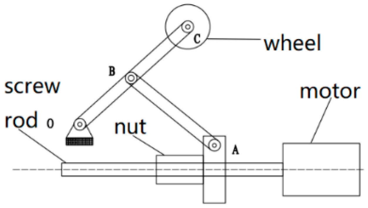
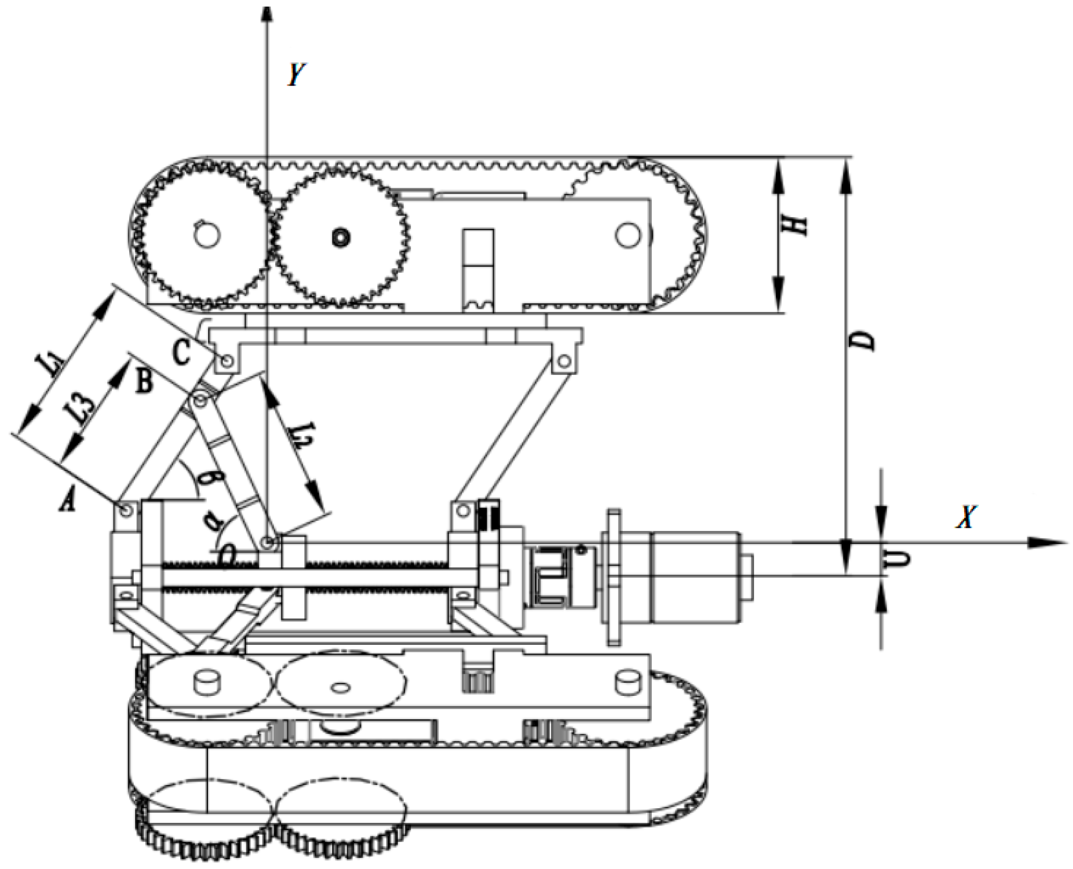
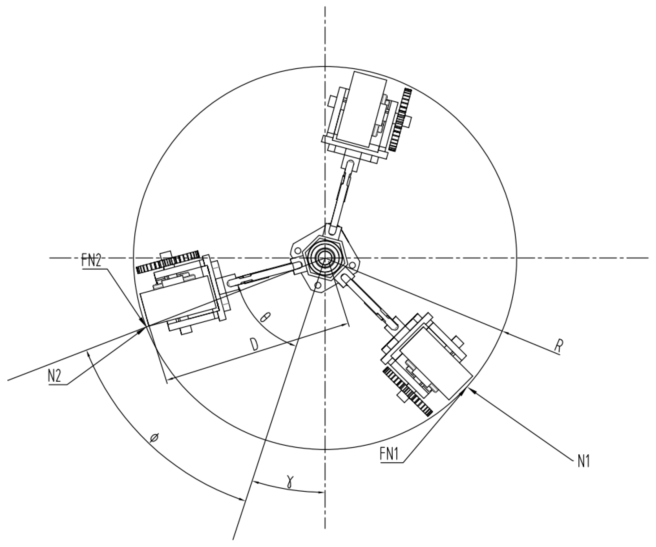
3.1. Force Analysis of Pipe Diameter Adaptation Mechanism

As shown in Figure 2 and Figure 3, X is the horizontal distance between points A and O, and D represents the radius of the robot. The distance from the support point to the lead screw is denoted as U, while the distance from the tail of the connecting rod to the traveling mechanism is represented by H. R is the radius of the pipe. AB, BO, and AC are denoted as L3, L2, and L1, respectively. The angle between OB and the lead screw is denoted as α, while the angle between AB and the X-axis is denoted as β. The angle between the connection line from the driving wheel to the center of the pipe and the center line of the pipe robot is φ, the arc length is represented by s, the attitude angle is γ, and θ is set to 60°.
The following conclusions can be drawn:
X = L 3 cos β + L 2 cos α L 3 sin β + U = L 2 sin α s = R φ D = L 1 sin β + U + H D sin θ = R sin φ Y = L 1 sin β + U
cos φ = R 2 D 2 s i n 2 θ R
According to the formula above, it follows that
F = ( 1 μ sin θ ) R 2 D 2 sin 2 θ R 2 D 2 sin 2 θ L 1 m g cos φ cos γ L 3 ( tan α + tan β )
As derived from the virtual displacement theorem,
F δ s + T δ ω η = 0
T is the output torque of the lead-screw motor and ƞ is the transmission efficiency of the lead screw. After arrangement, we obtain:
T = P 2 π η ( 1 μ sin θ ) R 2 D 2 sin 2 θ R 2 D 2 sin 2 θ L 1 m g cos φ cos γ L 3 ( tan α + tan β )
Here, P denotes the lead of the lead screw, and ω represents the rotation angle between the lead screw and the nut.
When the robot is in equilibrium, both the attitude angle and the inclination angle are 0°. According to Equation (5), when the pipe robot adapts to the maximum pipe diameter of 340 mm, α is 69.7° and β is 76.2°. When adapting to the minimum pipe diameter of 260 mm, α is 15.8° and β is 23.4°. From the output torque formula of the lead-screw motor, it is evident that the output torque of the lead screw is influenced by the values of α and β. Specifically, the output torque of the lead-screw motor is inversely proportional to these angles. As the length of AB increases, the required torque decreases. Conversely, as AB decreases, the output torque of the lead screw gradually increases, along with the thrust force F required for the operation of the variable-diameter mechanism. Moreover, the output torque of the lead-screw motor is inversely proportional to both the attitude angle and the inclination angle. When these angles deviate from 0°, a larger angle results in a smaller output torque of the lead screw and a greater required power. Therefore, the robot should endeavor to maintain balance within the pipe, align with the central axis of the pipe, and enhance the performance and efficiency of robotic operations.

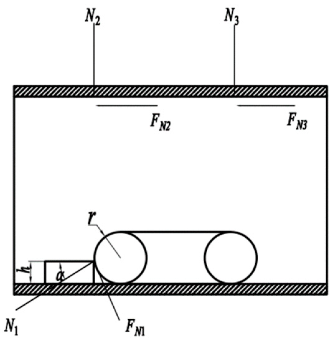
3.2. Analysis of the Robot’s Ability to Pass Obstacles

During the prolonged service of oil and gas pipelines, various degrees and forms of deformation may arise due to factors such as temperature fluctuations and pressure changes. These deformations can impact the internal space of a pipeline, thereby imposing higher demands on robots operating within it. Additionally, weld seams are an inevitable part of pipeline construction, and the uneven surface at these seams can impede the movement of robots within a pipeline. Therefore, designing a pipeline robot with robust obstacle-crossing capabilities is of paramount importance. For the purpose of analysis, we assumed that the obstacle was square, with a height h and a width of 20 mm. The forces acting on the robot are illustrated in Figure 4.
Applying the static equilibrium equations yields,
N 1 cos α μ 1 sin α = 2 μ N 2 + 2 μ N 3 N 1 sin α + μ 1 cos α = 2 N 2 cos 60 + 2 N 3 cos 60
where α is the obstacle-crossing angle; µ1 is the friction coefficient between the driving wheel and the obstacle; μ is the friction coefficient between the driving wheel and the pipe wall; and N1 is the reaction force of the obstacle on the driving wheel.
Simplifying N1 yields:
cos α μ 1 sin α sin α + μ 1 cos α = 2 μ
sin α = r h r cos α = r 2 r h 2 r = h 2 r h 1 r
Simplification yields:
h max = r ( 1 1 2 μ μ 1 1 + 2 μ + μ 1 2 )
Equation (9) presents the mathematical model for the maximum obstacle-crossing height of the oil and gas pipeline robot. Given parameters include r = 25 mm, µ = 0.4, and µ1 = 0.25. When one of the three sets of traveling mechanisms encounters an obstacle while the other two operate normally, the robot’s obstacle-crossing height is 14 mm. In a scenario where all three traveling mechanisms encounter a circular obstacle, with a friction coefficient of 0.25 between the driving wheels and the obstacle, the robot’s obstacle-crossing height is 7.5 mm.

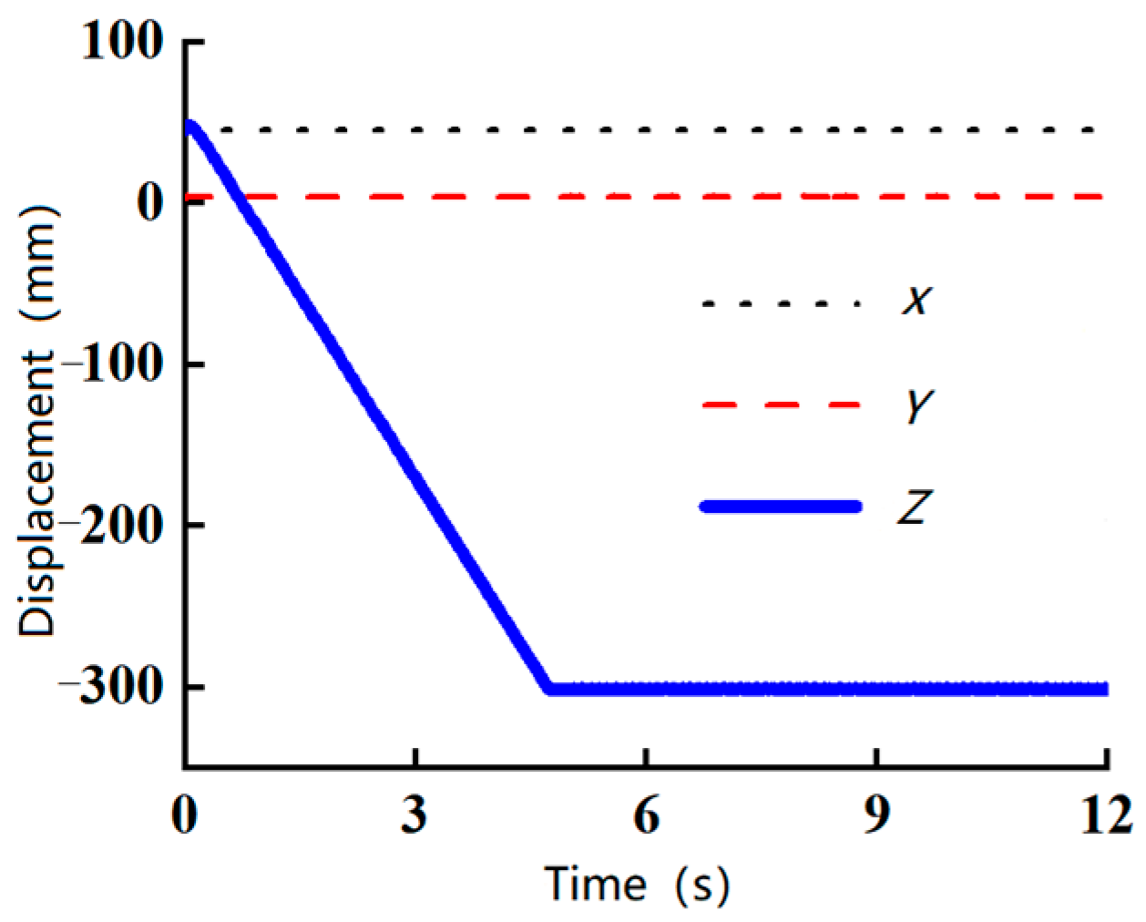
3.3. Simulation Analysis of Passing an Obstacle

Based on the maximum obstacle-crossing height determined through analysis, the robot was modeled and imported into ADAMS (Automatic Dynamic Analysis of Mechanical Systems) for simulation of its obstacle-crossing performance. The simulation was conducted in three scenarios, with obstacle heights set at 5 mm, 7.5 mm, and 10 mm to evaluate the robot’s ability to pass over these obstacles. Results of the simulation are presented below.
Figure 5, Figure 6 and Figure 7 illustrate centroid velocity diagrams of the robot as it traversed obstacles with heights of 5 mm, 7.5 mm, and 10 mm, respectively. These figures reveal that the front wheels of the robot’s crawler began to climb the obstacle at approximately 4.5 s, while the rear wheels started to pass over the obstacle at around 6.8 s. Comparing these three scenarios, it is evident that when the robot encountered a 5 mm obstacle, the Z-direction velocity exhibited significant fluctuations, but these were short-lived, whereas velocities along the X- and Y-axes remained relatively stable. The overall duration of velocity changes along all three axes was brief. In contrast, when traversing a 7.5 mm obstacle, the robot experienced substantial fluctuations in both Z- and Y-axis velocities, with a longer duration. Compared to the 5 mm obstacle, the robot took significantly longer to fully cross the 7.5 mm obstacle, completing the traversal at 9 s. When attempting to cross a 10 mm obstacle, the robot’s velocities in all three axes fluctuated severely from the moment the front wheels of the crawler engaged with the obstacle, and these fluctuations persisted throughout the simulation. Ultimately, the robot was unable to surmount the 10 mm circular obstacle.
Figure 8, Figure 9 and Figure 10 depict the velocity profiles of each wheel of the robot’s crawler when encountering obstacles of 5 mm, 7.5 mm, and 10 mm, respectively. These figures show that the robot’s wheel velocities all exhibited fluctuations around the 4.5 s mark, with the most pronounced fluctuations occurring when the robot encountered the 10 mm obstacle. During the second fluctuation, the timing for the 7.5 mm obstacle was delayed by approximately 0.5 s compared to the 5 mm obstacle. In contrast, the 10 mm obstacle caused persistent oscillations in wheel velocity from 4.5 s until the end of the simulation. Based on these observations, it can be concluded that the robot can smoothly pass over a 5 mm circular obstacle and barely pass a 7.5 mm obstacle, but is unable to surmount a 10 mm obstacle.
Figure 11, Figure 12 and Figure 13 illustrate the centroid displacement of the robot while traversing obstacles of 5 mm, 7.5 mm, and 10 mm, respectively. These figures indicate that the robot’s movement was directed along the negative Z-axis. When encountering the 5 mm obstacle, the robot exhibited minor fluctuations in displacement, while more pronounced fluctuations were observed at the 7.5 mm obstacle. Despite these fluctuations, the robot successfully traversed both obstacles. However, when attempting to pass the 10 mm obstacle, the robot’s Z-axis displacement ceased to change at around 4.5 s and remained constant for the duration of the simulation. This result confirms that the robot is unable to surmount a 10 mm obstacle.

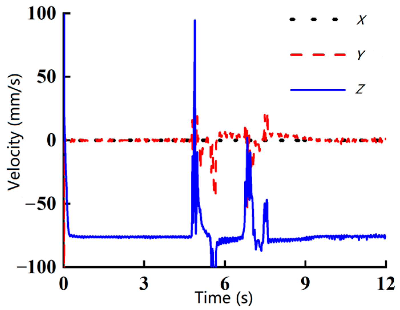
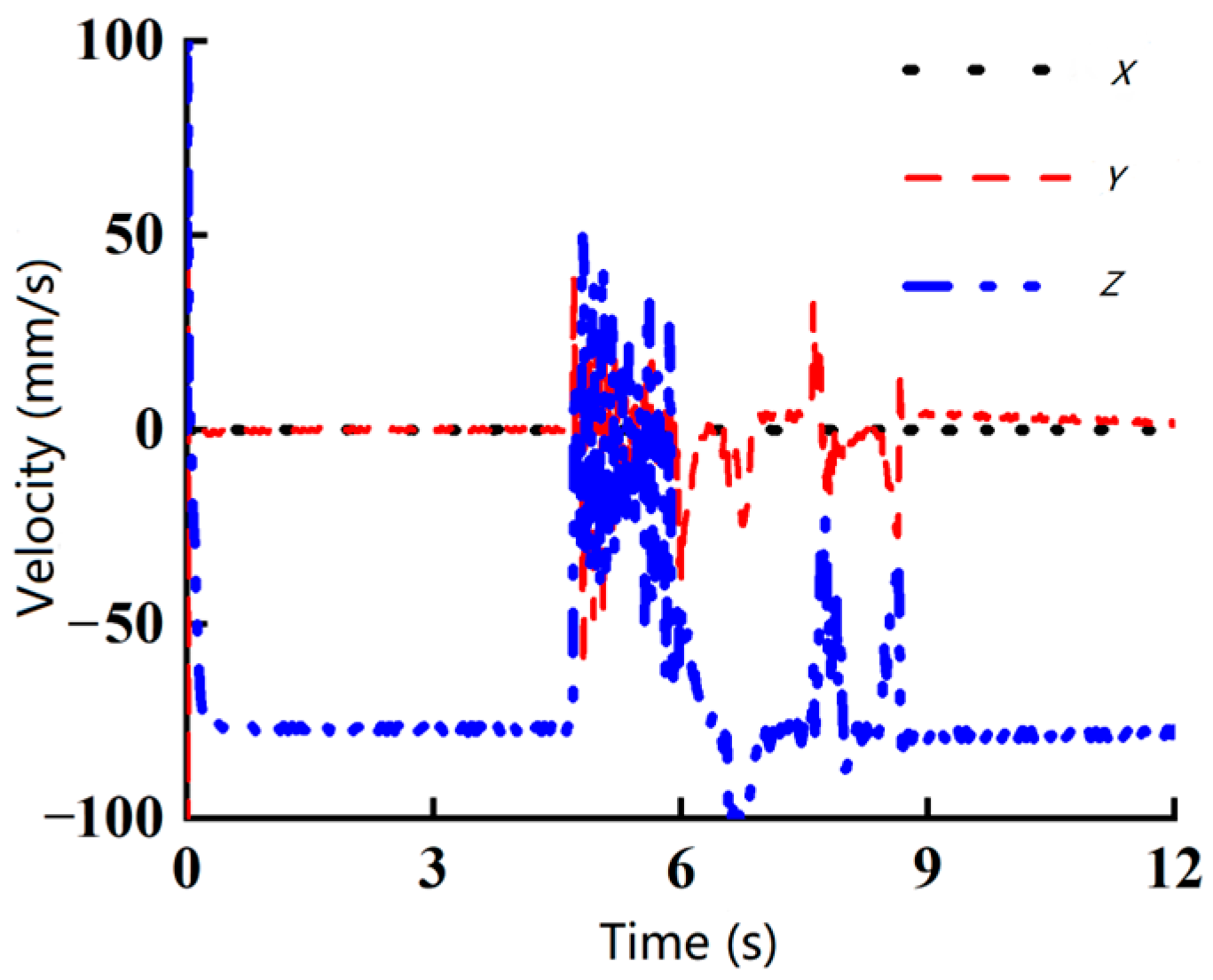
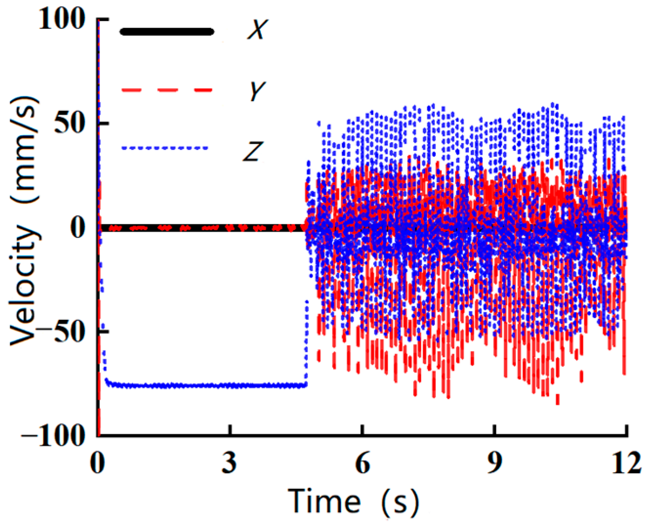
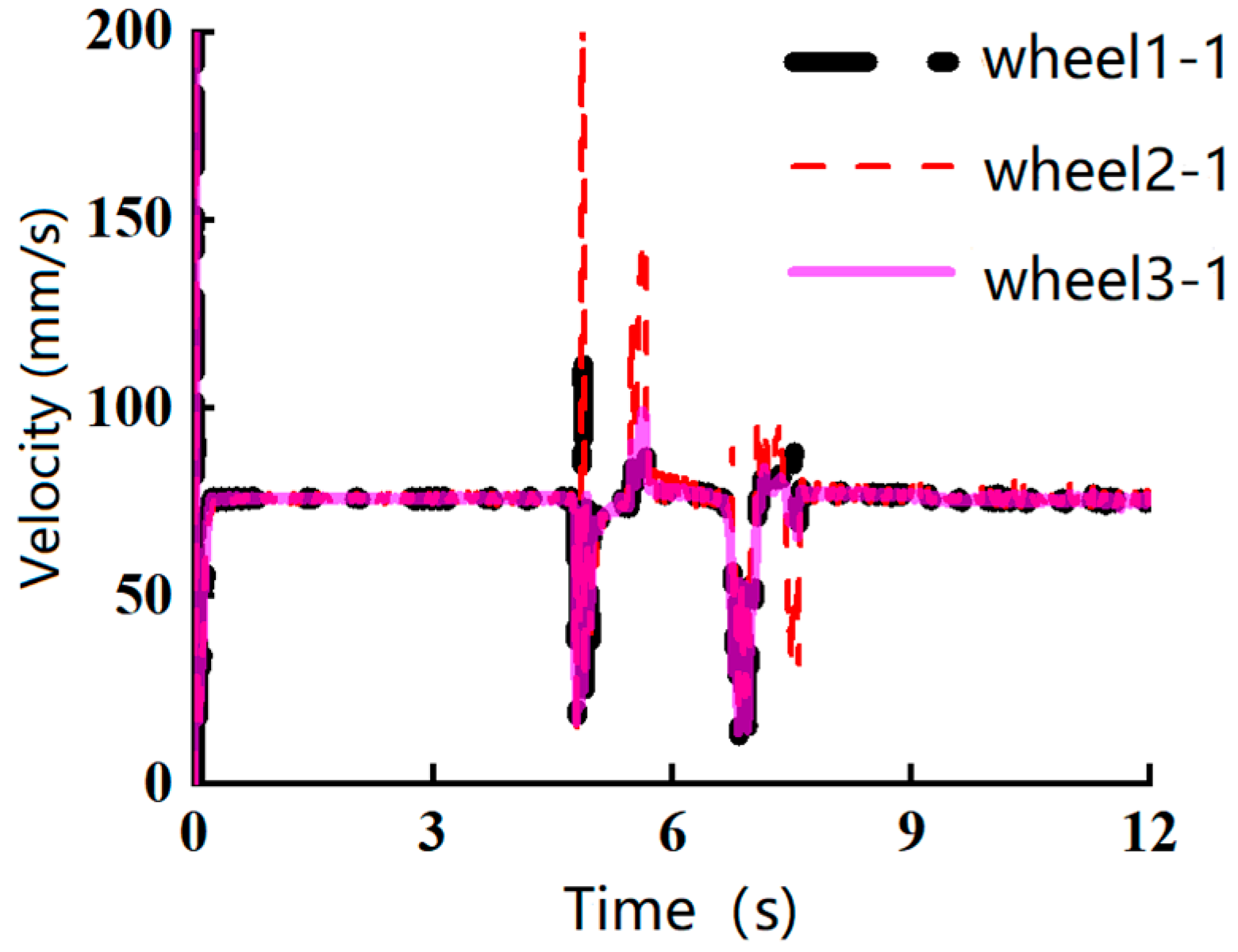
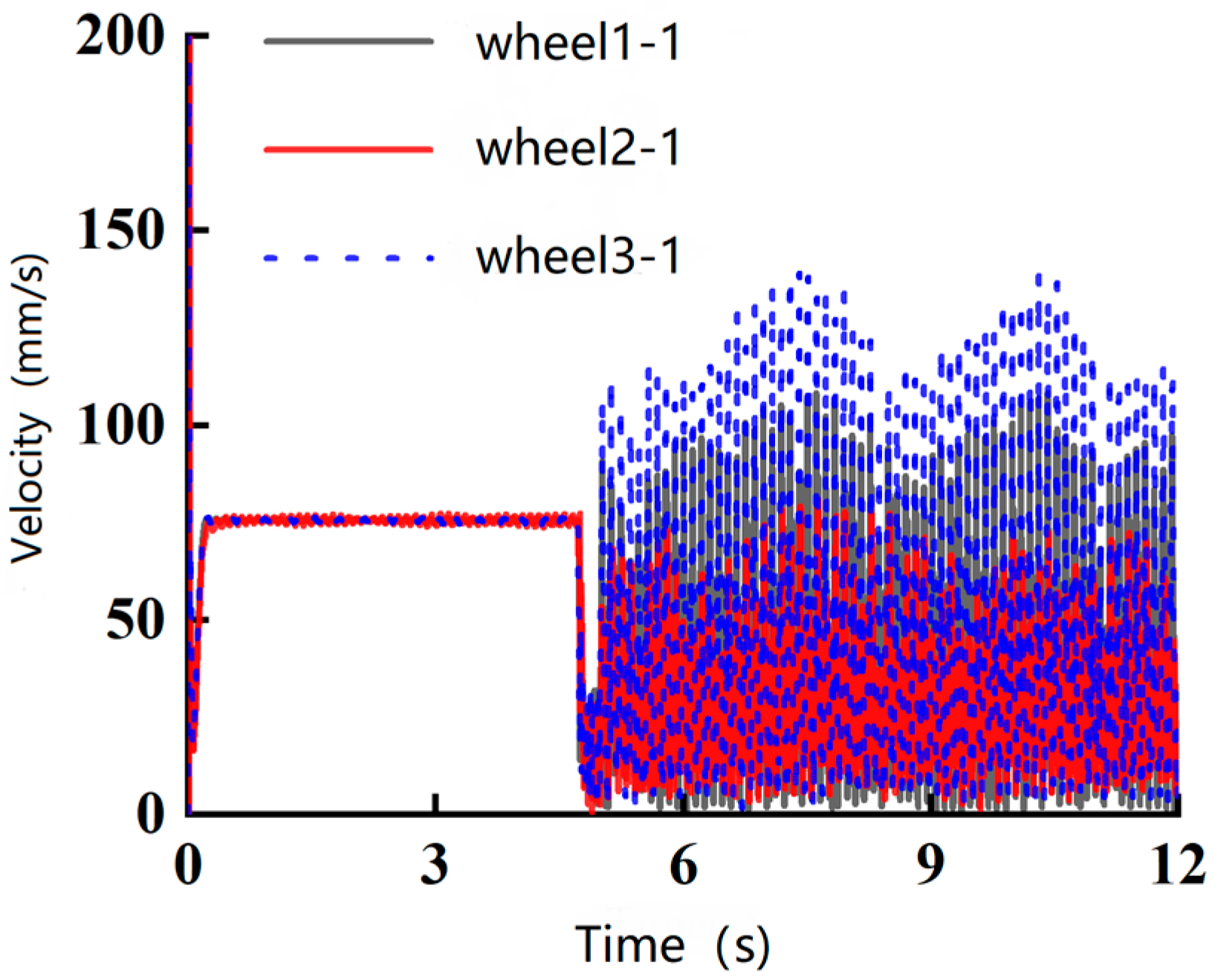
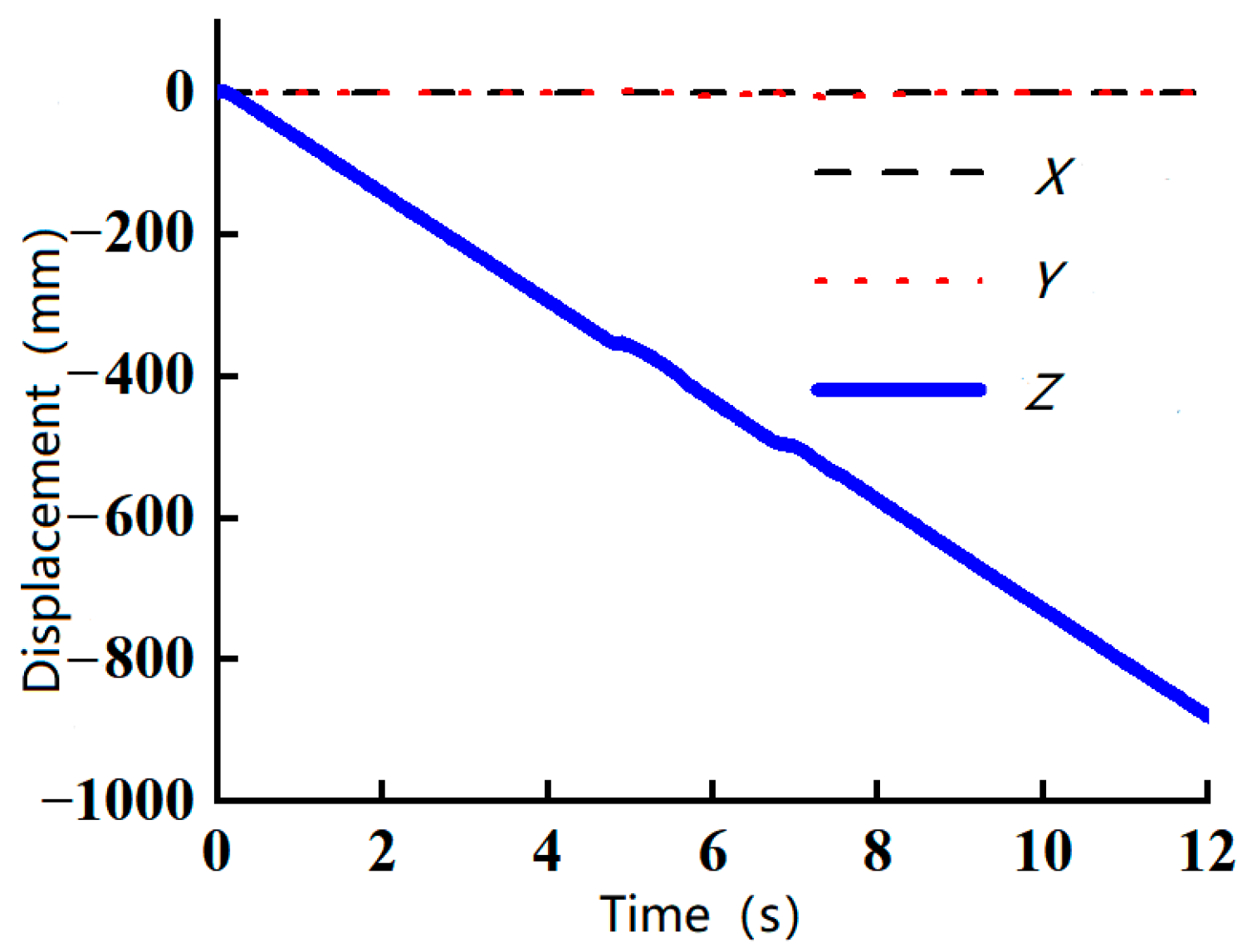
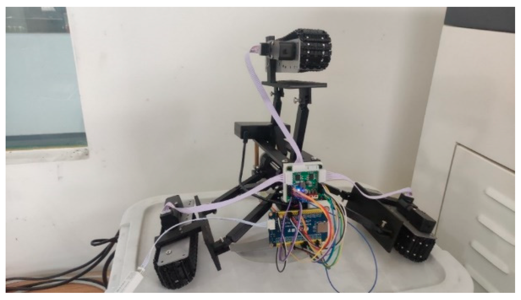
3.4. Prototype Testing and Analysis of the Robot

In accordance with the overall design scheme of the pipeline robot discussed in the preceding sections, the development of the pipeline robot prototype was successfully completed. The completed prototype is depicted in Figure 14. The pipe diameter adaptation mechanism primarily comprises the active rod, driven rod, lead-screw nut mechanism, lead-screw motor, and left and right support seats, among other components. The lead-screw nut mechanism serves as a crucial transmission element within the system. The lead-screw motor is connected to one end of the lead screw, and through the motor’s drive, the nut moves horizontally along the lead screw. Three connecting seats are evenly distributed at 120° intervals on the nut, and these connecting seats play a pivotal role in the mechanism’s function. As the nut moves, it drives the active rod to adjust its angle correspondingly, enabling the traveling mechanism to elevate or descend. This design not only enhances the flexibility of the mechanism, but also allows it to accommodate various pipe diameters. Two sets of driven rods form a parallelogram mechanism that connects the traveling mechanism to the support seat. The coordinated action of the active and driven rods enables the mechanism to adapt to different pipe diameters, thereby improving operational efficiency. The left and right support seats provide stable support for the mechanism, ensuring its stability during operation and preventing failures due to vibration or displacement.

3.4.1. Experimental Purpose

This study aimed to provide an in-depth analysis of the maximum obstacle-crossing height of the pipeline robot through mechanical modeling and simulation of obstacles with varying heights. Utilizing the previously derived formula for the maximum obstacle-crossing height, three groups of obstacles with distinct heights were designed for prototype testing: low (0 mm), medium (5 mm), and high (7.5 mm). Additionally, three parameters close to the maximum height—7.6 mm, 7.7 mm, and 7.8 mm—were selected to further test the robot’s capabilities. Through these prototype tests, the robot’s performance in traversing obstacles of different heights was intuitively assessed and analyzed.

3.4.2. Results of Prototype Testing

The following presents test results for the obstacle-crossing height of the pipeline robot. As indicated in Table 1, the robot was capable of normal traversal within a horizontal pipe at a speed of approximately 4.2 m/min. When encountering obstacles below 7.5 mm in height, the robot demonstrated swift passage, characterized by a short traversal time and high speed. However, when attempting to cross a 7.8 mm obstacle, the robot’s speed significantly decreased. The growth rate of passing time was highest when the obstacle height was 7.8 mm; based on Equation (10), and related to the current passing period (C) and the previous passing period (P), the traversal time markedly increased, suggesting that the robot struggled to surmount such a height. These findings corroborate the accuracy of the maximum obstacle-crossing height formula and highlight the challenges the pipeline robot faces when confronted with higher obstacles. The conclusions drawn from this simulation test are as follows: the maximum obstacle-crossing height of the pipeline robot is constrained by its dynamic performance and mechanical structure. Therefore, these factors should be thoroughly considered in future research and development efforts to enhance the robot’s obstacle-crossing capability. For environments with high obstacles, optimizing the robot’s structure or incorporating additional power devices could be explored to improve its traversal performance. Moreover, to more accurately assess the pipeline robot’s obstacle-crossing ability, future research should incorporate a broader range of real-world scenarios for testing and analysis. Additionally, other variables, such as obstacle shape and pipe diameter, should be included in the scope of research to gain a more comprehensive understanding of the robot’s performance across diverse environments.
Growth Rate = (C − P)/P

4. Discussion

This study addressed the challenges of pipeline maintenance by designing an in-pipe robot that integrates both active and passive variable-diameter mechanisms, in accordance with the current state of robot development. Based on the specific usage background and requirements, the pipe-diameter adaptation mechanism of the robot was meticulously designed and analyzed through mechanical modeling. The torque formula for the lead-screw motor was derived. According to the formula, when the robot adapts to the maximum diameter of 340 mm, α is 69.7° and β is 76.2°. When adapting to the minimum pipe diameter of 260 mm, α is 15.8° and β is 23.4°.
By constructing the obstacle mechanical model and the in-pipe pose model of the pipeline robot, the obstacle-crossing performance of the robot was thoroughly analyzed. The theoretical maximum obstacle-crossing height was determined to be 7.5 mm. The obstacle-crossing performance was tested through both ADAMS simulation and prototype experiments. Results indicated that the robot’s maximum obstacle-crossing height is 7.8 mm, which meets the design requirements and provides a solid foundation for further development and research of this robot.

Author Contributions

Conceptualization: L.Y.; formal analysis: F.L.; funding acquisition: L.Y.; investigation: P.L., L.Y. and F.L.; methodology: F.L.; resources: L.Y.; software: F.L.; visualization: F.L.; writing—original draft: P.L.; writing—review and editing: G.L., L.Y. and X.Z. All authors have read and agreed to the published version of the manuscript.

Funding

This research was funded by the National Natural Science Foundation of China, grant numbers 52375470 and 52005455; and the Central Guidance on Local Science and Technology Development Fund of Shanxi Province, grant number YDZJSX2022C005.

Institutional Review Board Statement

Not applicable.

Informed Consent Statement

Not applicable.

Data Availability Statement

The original contributions presented in this study are included in the article. Further inquiries can be directed to the corresponding author.

Acknowledgments

The authors acknowledge the technical support from the North University of China.

Conflicts of Interest

The authors declare no conflicts of interest. The funders had no role in the design of this study; in the collection, analysis, or interpretation of data; in the writing of this manuscript; or in the decision to publish these results.

References

  1. Ma, S.; Lyu, S.; Zhan, Q. Research on the Explosive Characteristics of Oil and Gas Mixture in Urban Drainage Pipeline. Chem. Eng. Trans. 2017, 62, 1399–1404. [Google Scholar] [CrossRef]
  2. Gao, Z.; Zhang, H.; Gao, P. New Progress in the Construction of Oil and Gas Pipelines in China in 2022. Int. Pet. Econ. 2023, 31, 16–23. [Google Scholar]
  3. Zhang, L. The “13th Five-Year” Energy Plan Requires Optimization in Three Aspects. Min. Mach. 2016, 44, 112–113. [Google Scholar]
  4. Gan, X.; Xu, B.; Dong, S. Development Status Quo of Pipeline Robot. Technol. Appl. Robot. 2003, 6, 2–5. [Google Scholar]
  5. Qi, A. Analysis of the Current Situation and Problems of Oil and Gas Pipeline Transportation Development in China. Int. Pet. Econ. 2009, 17, 1–2. [Google Scholar]
  6. Li, H.; Li, R.; Zhang, J.; Zhang, P. Development of a Pipeline Inspection Robot for the Standard Oil Pipeline of China National Petroleum Corporation. Appl. Sci. 2020, 10, 2853. [Google Scholar] [CrossRef]
  7. Tavakoli, M.; Marques, L.; Almeida, A.T.D. Development of an Industrial Pipeline Inspection Robot. Ind. Robot. 2010, 37, 309–322. [Google Scholar] [CrossRef]
  8. Chattopadhyay, P.; Ghoshal, S.; Majumder, A.; Dikshit, H. Locomotion Methods of Pipe Climbing Robots: A Review. J. Eng. Sci. Technol. Rev. 2018, 11, 154–165. [Google Scholar] [CrossRef]
  9. Xu, Z.; Yang, Z.; Zu, J. Impedance matching circuit for synchronous switch harvesting on inductor interface. In Proceedings of the 2015 IEEE International Conference on Mechatronics and Automation (ICMA), Beijing, China, 2–5 August 2015; IEEE: New York City, NY, USA, 2015. ISBN 9781479970988. [Google Scholar]
  10. Roslin, N.S.; Anuar, A.; Jalal, M.F.A.; Sahari, K.S.M. A Review: Hybrid Locomotion of in-Pipe Inspection Robot. Procedia Eng. 2012, 41, 1456–1462. [Google Scholar] [CrossRef]
  11. Wang, W.; Dong, W.; Su, Y.; Wu, D.; Du, Z. Development of Search-and-Rescue Robots for Underground Coal Mine Applications. J. Field Robot. 2014, 31, 386–407. [Google Scholar] [CrossRef]
  12. Yan, H.; Wang, L.; Li, P.; Wang, Z.; Yang, X.; Hou, X. Research on Passing Ability and Climbing Performance of Pipeline Plugging Robots in Curved Pipelines. IEEE Access 2020, 8, 173666–173680. [Google Scholar] [CrossRef]
  13. Wang, W.; Wang, X.; Zheng, G.; Chen, R.; Yuan, Z.; Huang, J.; Wu, K.; Bao, G. A Modular Soft Pipe-Climbing Robot with High Maneuverability. In IEEE/ASME Transactions on Mechatronics; IEEE: New York, NY, USA, 2024; pp. 4734–4743. [Google Scholar] [CrossRef]
  14. Zhao, Q.; Jiang, Z.; Chu, H.K. A Soft-Rigid Air-Propelled Pipe-Climbing Robot. In Proceedings of the IEEE International Conference on Robotics and Automation, Hong Kong, 21–23 April 2021; Institute of Electrical and Electronics Engineers Inc.: New York City, NY, USA, 2021; Volume 2021, pp. 11850–11855. [Google Scholar]
  15. Kim, J.H.; Lee, J.C.; Choi, Y.R. PiROB: Vision-Based Pipe-Climbing Robot for Spray-Pipe Inspection in Nuclear Plants. Int. J. Adv. Robot. Syst. 2018, 15, 1729881418817974. [Google Scholar] [CrossRef]
  16. Li, J.; Huang, F.; Tu, C.; Tian, M.; Wang, X. Elastic Obstacle-Surmounting Pipeline-Climbing Robot with Composite Wheels. Machines 2022, 10, 874. [Google Scholar] [CrossRef]
  17. Han, S.; Ahn, J.; Moon, H. Remotely Controlled Prehensile Locomotion of a Two-Module 3D Pipe-Climbing Robot. J. Mech. Sci. Technol. 2016, 30, 1875–1882. [Google Scholar] [CrossRef]
  18. Lee, S.H. Design of the Out-Pipe Type Pipe Climbing Robot. Int. J. Precis. Eng. Manuf. 2013, 14, 1559–1563. [Google Scholar] [CrossRef]
  19. Tu, Q.; Liu, Q.; Ren, T.; Li, Y. Obstacle Crossing and Traction Performance of Active and Passive Screw Pipeline Robots. J. Mech. Sci. Technol. 2019, 33, 2417–2427. [Google Scholar] [CrossRef]
  20. Ylikorpi, T.J.; Halme, A.J.; Forsman, P.J. Dynamic Modeling and Obstacle-Crossing Capability of Flexible Pendulum-Driven Ball-Shaped Robots. Robot. Auton. Syst. 2017, 87, 269–280. [Google Scholar] [CrossRef]
  21. Toussaint, K.; Pouliot, N.; Montambault, S. Transmission Line Maintenance Robots Capable of Crossing Obstacles: State-of-the-Art Review and Challenges Ahead. J. Field Robot. 2009, 26, 477–499. [Google Scholar] [CrossRef]
  22. Yu, J.; Zhang, D.; Dai, Y. Analysis of the Climbing Characteristics of a Crawler-Type Oil and Gas Pipeline Inspection Robot. Tools Hydraul. 2023, 51, 57–61. [Google Scholar]
  23. Chen, P.; Gao, F. Mechanism Design and Motion Analysis of Circular Pipeline Robot. Heavy Mach. 2023, 2, 103–108. [Google Scholar] [CrossRef]
  24. Zhang, X.; Fu, K.; Chen, M. Dynamic Evolution Law and Vibration Reduction Analysis of a Differential Pressure Type Multi-Section Series Pipeline Robot When Crossing Obstacles. J. Mech. Eng. 2024, 60, 1–8. [Google Scholar]
  25. Zhang, Y.; Dong, L.; Huan, R. Design and Kinematic Analysis of Crawler-Type Pipeline Endoscope Robots for Wind Turbine Blades. China Mech. Eng. 2021, 32, 1884–1889. [Google Scholar]
  26. Liu, D.; Liu, J. Asymmetric Inertia Driving System for In-Pipe Robots and Its Dynamics Characteristics. China Mech. Eng. 2020, 31, 2189–2195+2205. [Google Scholar]
  27. Yue, M.; Deng, Z. Dynamic Modeling and Optimal Controller Design of a Spherical Robot in Climbing State. Jixie Gongcheng Xuebao/J. Mech. Eng. 2009, 45, 46–51. [Google Scholar] [CrossRef]
  28. Tang, D.; Li, Q.; Liang, T.; Jiang, S.; Deng, Z. Mechanical Self-Adaptive Drive Technology of Triaxial Differential Pipe-Robot. J. Mech. Eng. 2008, 30, 128–133. [Google Scholar] [CrossRef]
  29. Qi, L.; Zhang, T.; Xu, K.; Pan, H.; Zhang, Z.; Yuan, Y. A Novel Terrain Adaptive Omni-Directional Unmanned Ground Vehicle for Underground Space Emergency: Design, Modeling and Tests. Sustain. Cities Soc. 2021, 65, 102621. [Google Scholar] [CrossRef]
  30. Verma, M.S.; Ainla, A.; Yang, D.; Harburg, D.; Whitesides, G.M. A Soft Tube-Climbing Robot. Soft Robot. 2018, 5, 133–137. [Google Scholar] [CrossRef] [PubMed]
  31. Kanada, A.; Giardina, F.; Howison, T.; Mashimo, T.; Iida, F. Reachability Improvement of a Climbing Robot Based on Large Deformations Induced by Tri-Tube Soft Actuators. Soft Robot. 2019, 6, 483–494. [Google Scholar] [CrossRef]
  32. Aracil, R.; Saltarén, R.; Reinoso, O. Parallel Robots for Autonomous Climbing along Tubular Structures. Robot. Auton. Syst. 2003, 42, 125–134. [Google Scholar] [CrossRef]
  33. Ling, Z.; Chen, Y.; Tang, J.; Zheng, M. Development and Design of Self-Adaptive Variable Diameter Robot for In-Pipe Inspection. In Proceedings of the IOP Conference Series: Materials Science and Engineering, Chennai, India, 16–17 September 2020; Institute of Physics Publishing: Bristol, UK, 2020; Volume 782. [Google Scholar]
Figure 1. Screw and nut diameter-changing mechanism.
Applsci 15 05905 g001
Figure 2. Mechanical model of pipe diameter adaptation mechanism.
Applsci 15 05905 g002
Figure 3. In-pipe pose of pipeline robot.
Applsci 15 05905 g003
Figure 4. Force diagram of pipe robot for obstacle crossing.
Applsci 15 05905 g004
Figure 5. The centroid velocity when passing a 5 mm obstacle.
Applsci 15 05905 g005
Figure 6. The centroid velocity when passing a 7.5 mm obstacle.
Applsci 15 05905 g006
Figure 7. The centroid velocity when passing a 10 mm obstacle.
Applsci 15 05905 g007
Figure 8. The velocity of the robot’s wheels when passing a 5 mm obstacle.
Applsci 15 05905 g008
Figure 9. The velocity of the robot’s wheels when passing a 7.5 mm obstacle.
Applsci 15 05905 g009
Figure 10. The velocity of the robot’s wheels when passing a 10 mm obstacle.
Applsci 15 05905 g010
Figure 11. The 5 mm centroid displacement.
Applsci 15 05905 g011
Figure 12. The 7.5 mm centroid displacement.
Applsci 15 05905 g012
Figure 13. The 10 mm centroid displacement.
Applsci 15 05905 g013
Figure 14. Pipeline robot prototype for testing.
Applsci 15 05905 g014
Table 1. Testing results.
Serial NumberHeight (mm)Passing Period (s)Velocity (m/min)Growth Rate (%)
1044.2\
2550.2425
37.570.1540
47.8150.045114.29
57.67.50.127.14
67.78.50.0813.33
Disclaimer/Publisher’s Note: The statements, opinions and data contained in all publications are solely those of the individual author(s) and contributor(s) and not of MDPI and/or the editor(s). MDPI and/or the editor(s) disclaim responsibility for any injury to people or property resulting from any ideas, methods, instructions or products referred to in the content.

