Article

Generative Artificial Intelligence-Enabled Facility Layout Design Paradigm

School of Mechanical and Material Engineering, North China University of Technology, Beijing 100144, China
*
Author to whom correspondence should be addressed.
Appl. Sci. 2025, 15(10), 5697; https://doi.org/10.3390/app15105697
Submission received: 6 March 2025 / Revised: 16 May 2025 / Accepted: 17 May 2025 / Published: 20 May 2025

Abstract

:

Featured Application

A generative AI-driven and Industry 4.0-compliant approach for facility layout design is proposed to enable end-to-end facility layout generation.

Abstract

Facility layout design (FLD) is critical for optimizing manufacturing efficiency, yet traditional approaches struggle with complexity, dynamic constraints, and fragmented data integration. This study proposes a generative-AI-enabled facility layout design, a novel paradigm aligning with Industry 4.0, to address these challenges by integrating generative artificial intelligence (AI), semantic models, and data-driven optimization. The proposed method evolves from three historical paradigms: experience-based methods, operations research, and simulation-based engineering. The metamodels supporting the generative-AI-enabled facility layout design is the Asset Administration Shell (AAS), which digitizes physical assets and their relationships, enabling interoperability across systems. Domain-specific knowledge graphs, constructed by parsing AAS metadata and enriched by large language models (LLMs), capture multifaceted relationships (e.g., spatial adjacency, process dependencies, safety constraints) to guide layout generation. The convolutional knowledge graph embedding (ConvE) method is employed for link prediction, converting entities and relationships into low-dimensional vectors to infer optimal spatial arrangements while addressing data sparsity through negative sampling. The proposed reference architecture for generative-AI-enabled facility layout design supports end-to-end layout design, featuring a 3D visualization engine, AI-driven optimization, and real-time digital twins. Prototype testing demonstrates the system’s end-to-end generation ability from requirement-driven contextual prompts and extensively reduced complexity of modeling, integration, and optimization. Key innovations include the fusion of AAS with LLM-derived contextual knowledge, dynamic adaptation via big data streams, and a hybrid optimization approach balancing competing objectives. The 3D layout generation results demonstrate a scalable, adaptive solution for storage workshops, bridging gaps between isolated data models and human–AI collaboration. This research establishes a foundational framework for AI-driven facility planning, offering actionable insights for AI-enabled facility layout design adoption and highlighting future directions in the generative design of complex engineering.

1. Introduction

Conceptually, facility layout design (FLD) or facility layout planning (FLP) is an extensive terminology that encompasses the design of factories as well as hospitals, airports, retail stores, and other types of facilities [1]. Owing to the importance and complexity of production or manufacturing systems, the vast majority of research on FLD has focused on factory layout design or shop-floor design [2]. Therefore, the terms facility layout design, factory layout planning, and shop-floor layout are often used interchangeably. Macroscopically, FLD is inherently connected to the strategic planning of production and product development, as well as the planning of processes, machines, and equipment [3]. Facility layout design is crucial for optimizing production efficiency by strategically arranging resources, workstations, and equipment to streamline material flow, minimize transportation time, and reduce costs. FLD can be further divided into concept layout and detailed layout planning. A concept layout includes a coarse spatial representation of functional units with only limited consideration of detailed influences. These details are covered by the subsequent step of detailed layout planning. Generally, there are four basic types of layout, which are fixed-position layout, process layout, cellular layout, and product layout [4]. Each kind of layout has its own distinct advantages depending on the nature of the production process, types of product, and the production volume [5]. However, for a long time, no matter in theory or in practice, the problem of FLD was notoriously difficult for its complexity, and there is no ideal formulation method so far. Smith [6] argued that factory design problems inevitably face ten crucial dilemmas and corresponding deep-seated underlying paradoxes. In essence, the factory design process is essentially information-deficient and is an argumentative and dynamic process [7].
Mathematically, FLD can be modeled in discrete or continuous formulations based on spatial arrangement variables [8,9]. In discrete FLD, space is divided into a finite set of predefined locations (grid points or nodes), with components assigned to these locations. In continuous FLD, component placement is treated as a continuous variable, offering greater flexibility in design [10]. Layout alternatives are typically deduced using mathematical optimization models: discrete quadratic programming models for equal-sized departments or continuous linear or nonlinear mixed-integer programming models for departments of varying sizes. The design space should be defined by appropriate target criteria, decision variables, and constraints to offer a well-balanced solution set; yet, currently, there are no general guidelines or theoretical studies on the optimal number of goals, variables, and boundaries to achieve a suitable balance between efficiency and complexity [11]. According to computational complexity theory, FLD is a non-deterministic polynomial (NP) hard problem, meaning no algorithms guarantee an optimal solution in polynomial time [12]. To efficiently generate good layouts for large-scale problems, heuristic and metaheuristic approaches [13], as well as machine learning approaches [14], have been introduced to find near-optimal solutions within a reasonable computational time [15]. For complex scenarios, such as for lean, flexible, or agile manufacturing, dynamic or stochastic production uncertainties must be considered in the design. Uncertainty affects the stability of the Pareto set and can undermine the decision-making process [16]. FLD can be categorized as static or dynamic depending on input requirements and time frame. Static facility layout problems assume constant flow between machines, product demand, and product mix, typically addressing a single time period. Dynamic facility layout problems, however, involve periodic evaluation and adjustment based on changing conditions [17]. A plant planner may prefer a robust layout, which may not be optimal for any of the scenarios, but it has good adaptivity under each scenario [18,19]. The interplay of strategic and tactical planning significantly impacts the design process.
Around the beginning of this century, many studies began exploring FLD methods using advanced computerized tools and simulation platforms [20]. The use of simulation platforms, in particular, provided a way to visualize and test different layout alternatives in a virtual environment before implementation, reducing the risk of costly trial-and-error approaches in real-world applications [21,22]. Although simulation-based methods offer advantages in guiding factory layout, which can help alleviate some of the challenges faced by traditional methods, simulation-based or model-based system engineering (MBSE) approaches for FLD still involve a steep learning curve and require time-consuming effort to gather data and build accurate 3D models of facilities. It is difficult to select or build the appropriate models required for factory design in advance, independent of the client and the specific context in which the problem arises. Poor modeling can result in simulations that fail to reflect a facility’s actual dynamics, leading to poor design decisions that fail to optimize space and flow efficiency [23]. Incomplete or inaccurate data can cause unrealistic simulations, leading to design flaws in the final layout. Even small data errors can create large discrepancies in the results. Moreover, simulations often need to be integrated with other analytical or decision-making tools, such as optimization algorithms, statistical analysis, or machine learning models [24]. In brief, there are still significant obstacles in simulation-based FLD, including high integration complexity, optimization complexity and modeling complexity, which make it impossible to achieve the end-to-end task from concepts to layout generation [25].
The fourth industrial revolution (Industry 4.0) is fundamentally transforming the global manufacturing landscape. Industry 4.0 integrates several key technologies, such as the Internet of Things (IoT), big data analytics, digital twin (DT), additive manufacturing, and intelligent robots into manufacturing environments [26,27]. This convergence is driving the development of smart factories, where production systems are highly interconnected and seamlessly integrated, resulting in transformative shifts in how manufacturing processes are executed. The foundational principles of Industry 4.0, such as autonomy, interoperability, decentralization, distributed systems, service-oriented architectures, scalability, virtualization, transparency, seamless integration, and real-time capabilities, are pivotal in driving the digital transformation of production and value creation [28]. A defining feature of Industry 4.0 is its ability to enable horizontal integration across value networks. This involves converging information technology systems across various stages of manufacturing and business planning, facilitating seamless data exchange within individual companies and across multiple organizations. Vertical integration and networked manufacturing are also pivotal, enabling the convergence of information systems at different hierarchical levels to create comprehensive solutions that extend from the factory floor to the enterprise level. These interconnected features have contributed to the rise in the smart factory, where the physical and digital realms have been merged through the development of smart products and processes that redefine traditional value chains [29]. Another important aspect is end-to-end digital integration, which spans the entire value chain, ensuring all steps are digitally connected. The horizontal, vertical, and end-to-end integrations have led to the creation of cyber–physical systems (CPSs), where physical production components are closely intertwined with digital technologies. In this environment, a DT serves as a virtual replica of a physical entity, continuously updated to reflect the state of its real-world counterpart, further enabling operational efficiency and innovation [30,31,32,33]. However, as industrial environments undergo rapid transformation, the increasing complexity and connectivity of these systems have introduced new challenges [34,35]. This evolving environment calls for more advanced, flexible, and data-driven approaches to decision making, ensuring that smart factories and cyber–physical production systems can thrive in the face of continuous change [36]. Following the vision of Industry 4.0, we believe that the following gaps remain in the FLD field.
First, in the existing methods, facility layout, data, models, information, and algorithms are highly isolated. The isolation or fragmentation of digital 3D product models, the functional capacity of equipment, and the process data or domain knowledge in the current facility layout methods has led to inefficiencies and missed optimization opportunities. Functional data, including machine capabilities and production processes, are typically maintained separately, hindering efficient space utilization and workflow optimization [37]. Furthermore, fragmented equipment models and static layouts fail to adapt to changes, while disconnects between strategic and operational planning stages lead to suboptimal facility designs [38]. Optimization models often focus on isolated sub-problems and lack real-time adaptability.
Second, the existing facility layout methods are primarily human-driven, with limited integration between human intelligence and artificial intelligence (AI). Whether using a top-down or bottom-up approach, these methods involve stakeholders from various levels with their own localized concerns, information, and expertise. As a result, planners who cannot grasp global information and knowledge are required to make multiple iterations, which delays the final design and introduces inefficiencies. Traditional approaches often use rule-based or heuristic methods, with limited automation or AI assistance. This lack of synergy limits the effectiveness of AI. AI agentic workflows will drive significant progress in tool use, planning and multiagent collaboration, simulation capabilities, and automated optimization [39].
Third, the existing facility layout methods lack standardized frameworks, leading to inconsistencies and difficulties in the integration and interoperability of multi-source heterogeneous information. This lack of standardization and interoperability hinders the effective integration of modern technologies and best practices, preventing facilities from fully utilizing the capabilities of Industry 4.0 [40]. Specifically, the absence of clear specifications or adaptable models makes it challenging to incorporate automation, IoT devices, and real-time data streams. Without AI-driven tools and standardized processes, the existing layouts often struggle to deliver the efficiency, flexibility, and scalability required to stay competitive in a rapidly changing technological landscape.
To address these challenges, it is essential to adopt integrated, intelligent systems that can automate and optimize the layout planning process. These systems would ensure greater standardization, facilitate real-time end-to-end design, and enable seamless integration with advanced technologies such as digital twins and the industrial IoT, allowing facilities to better meet the demands of the Industry 4.0 era. To narrow the above gaps, this work provides contributions from three aspects:
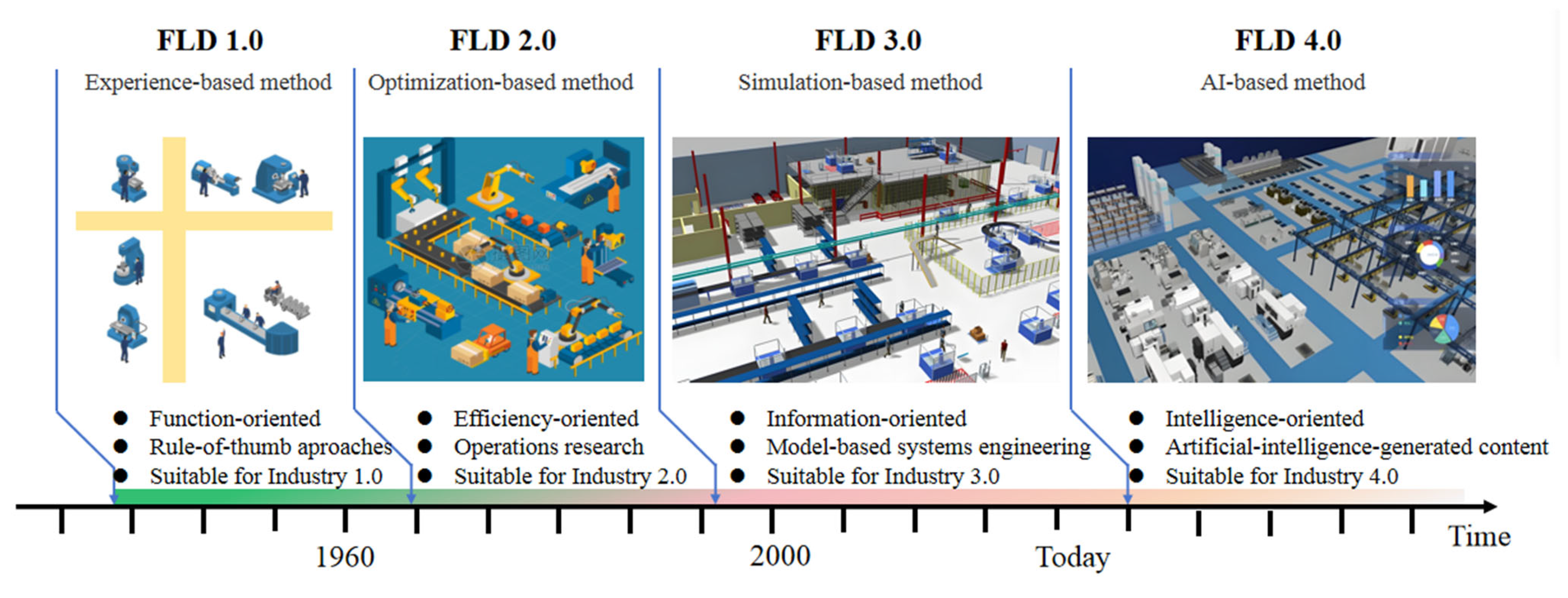
  • This work outlines the evolution of facility layout design through three historical paradigms: experience-based methods (FLD 1.0), operations-research-based approaches (FLD 2.0), and simulation-based engineering (FLD 3.0), especially positioning FLD 4.0 as a generative-AI-driven and Industry 4.0-compliant approach.
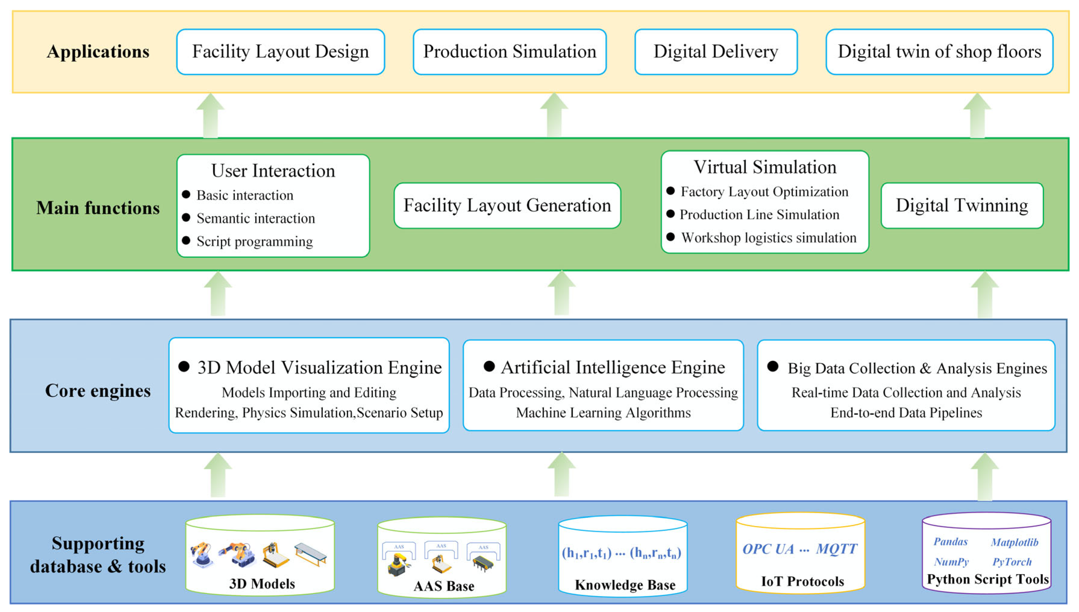
  • This research introduces a basic reference architecture for the FLD 4.0 paradigm that integrates the Asset Administration Shell (AAS), knowledge graphs, and generative AI, emphasizing interoperability, real-time adaptability, and human–AI collaboration.
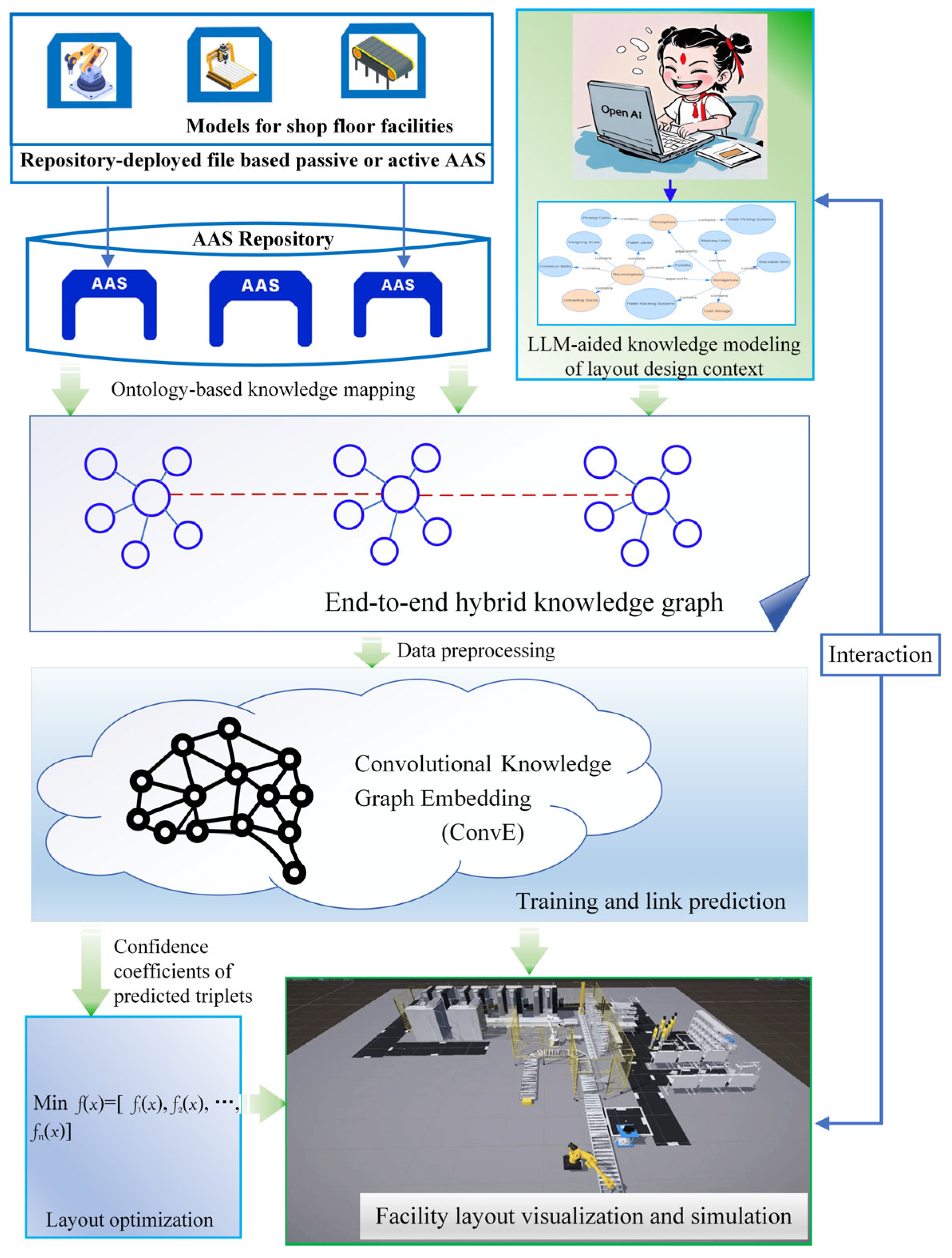
  • We developed a functional prototype that combines AAS, large language models (LLMs), embedding-based knowledge graph reasoning, and 3D visualization tools to enable end-to-end facility layout generation.

2. Evolution of Facility Layout Design Paradigms

A paradigm is a typical example or pattern of something; it often represents a framework or model that shapes our understanding and perspective of complex concepts or systems. Paradigms provide a structured framework that organizes knowledge and facilitate the comprehension of complex issues. A clear understanding of current and emerging paradigms can inform decision-making processes, ensuring that strategies are aligned with the direction in which industries and societies are evolving. For example, recognizing the shift toward Industry 4.0 emphasizes the needs for data-driven decision making and connectivity, which precede the emerging Industry 5.0 focus on human-centered systems [28,41]. To conclude, by anchoring analyses in established paradigms, one can derive insights that are both deep and broadly applicable in confronting complex challenges.
To systematically catch the evolutionary trends in FLD, we propose a structured paradigm framework for FLD. This framework categorizes and delineates the key phases, methodologies, and technological advancements that have influenced FLD over time. As illustrated in Figure 1 and Table 1, the evolution can be categorized into four distinct paradigms: manual and rule-of-thumb approaches (FLD 1.0), the operations research paradigm (FLD 2.0), simulation-based systems engineering (FLD 3.0), and the emerging generative-AI-enabled method (FLD 4.0). This evolution reflects the broader trends in industrial development from the early days of mechanization in Industry 1.0 to the interconnected, smart manufacturing ecosystems of Industry 4.0.

2.1. Facility Layout Design 1.0: Experience-Based Methods

The first stage of facility layout design (FLD 1.0) emerged during the early stages of industrialization, particularly in Industry 1.0. At this point, manufacturing was characterized by rudimentary production techniques, limited automation, and manual labor. The methods in this stage were largely experience-based and rule-of-thumb approaches. These methodologies were grounded in practical knowledge, drawing heavily on the personal experience and intuition of managers and planners rather than on formal mathematical models or data-driven approaches. The focus was primarily function-oriented, with the primary aim being the placement of machines, tools, and workstations in a manner that facilitated basic production tasks, often with little regard for optimizing efficiency or minimizing costs. Given the relatively simple and static nature of early manufacturing processes, these methods were largely sufficient to address the layout challenges of the time. However, the approaches lacked precision and scalability, and their reliance on human judgment limited their ability to handle more complex production environments as industries began to expand.

2.2. Facility Layout Design 2.0: Optimization-Based Methods

With the advent of Industry 2.0, marked by the rise in mass production, the mechanization of manufacturing processes, and the increase in automation, the paradigm for facility layout design underwent a significant transformation. This period, often associated with the early to mid-20th century, saw the development of FLD 2.0, an optimization-based method that sought to improve efficiency through operations research (OR) techniques. Systematic layout planning (SLP) can indeed be regarded as the starting point or foundational methodology for FLD 2.0 because it introduced a systematic, step-by-step approach to organize the arrangement of equipment, workstations, and storage areas to optimize operational efficiency and reduce costs [42,43]. It emphasized the importance of understanding processes, workflows, and interdependencies before finalizing the physical arrangement of a facility. FLD 2.0 was inherently efficiency-oriented, with a primary focus on reducing operational costs and maximizing output within the constraints of the available resources. The integration of OR techniques marked a major advancement over previous experience-based methods, as they introduced a level of scientific rigor and quantitative analysis that was previously lacking. The optimization-based methods of FLD 2.0 were particularly suited for the more structured and predictable production processes of Industry 2.0, where mass production, assembly lines, and relatively stable market demands dominated the manufacturing landscape.
OR techniques enable organizations to effectively optimize decision making and enhance operational efficiency. Multi-attribute decision-making (MADM) is used when the decision-making process involves a finite number of alternatives that need to be evaluated against multiple attributes or criteria. Various methods such as the weighted sum model (WSM), technique for order preference by similarity to ideal solution (TOPSIS) [44], and analytic hierarchy process (AHP) [45] are employed to evaluate and rank alternatives. In contrast, multi-objective decision making (MODM) deals with problems where the decision-making situation involves an infinite number of solutions or design variables. Contemporary methods in OR incorporate a variety of tools such as linear programming, dynamic programming, simulation models, and heuristic techniques, including genetic algorithms, significantly enhancing organizational efficiency [46].
However, the implementation of OR methods to address complex practical problems often encounters significant bottlenecks and shortcomings. One primary challenge is the reliance on high-quality input data; inaccuracies, missing values, or outdated information can result in flawed models. Furthermore, collecting sufficient data can be particularly difficult in dynamic environments where conditions are rapidly changing [47]. OR techniques typically involve simplifying assumptions about real-world processes to create manageable models. However, these assumptions may not always reflect reality, potentially undermining the validity of the resulting solutions [48]. In summary, although OR provides valuable methodologies for solving intricate practical issues, its implementation is hindered by various bottlenecks associated with data quality, model assumptions, complexity, system integration, and communication dynamics. Consequently, FLD 2.0 is limited by the lack of real-time data and the complexity of integrating multiple systems, which becomes more pronounced as manufacturing environments grow increasingly sophisticated.

2.3. Facility Layout Design 3.0: Simulation-Based Systems Engineering

As industries evolved further into Industry 3.0, the introduction of information technology, automation, and more complex production systems necessitated a more sophisticated approach to facility layout design. This period marked the rise of FLD 3.0, characterized by the adoption of digital models and visualized simulation. FLD 3.0 relies on digital models and simulation-based approaches to create dynamic and adaptable layouts. This approach is highly effective in addressing the growing complexity of Industry 3.0, where automated machinery, robots, and interconnected systems required a more holistic approach to layout design. This simulation-oriented method marks a key shift from the optimization models of FLD 2.0, as it emphasizes the value of continuous feedback loops, real-time visualization, and predictive analytics. One critical application of simulation is in workshop layout design, where software solutions such as FlexSim (https://www.flexsim.com/), AnyLogic (https://www.anylogic.com/), and Plant Simulation (https://plm.sw.siemens.com/en-US/tecnomatix/plant-simulation-software/, accessed on 16 May 2025) provide powerful functionalities to visualize and evaluate different configurations before implementation [49,50]. By using discrete event simulation (DES), these applications allow users to model systems where changes occur at distinct time intervals due to specific events. By analyzing different layout options, businesses can identify the optimal configurations that minimize travel times, reduce bottlenecks, and streamline workflows [51]. Continuous simulation may also play a role by modeling how dynamic factors like inventory levels and production rates influence layout effectiveness over time. The purpose of these simulations extends beyond mere design; they are instrumental in performance evaluation [52,53].
From the data handling perspective, these simulation tools support both deterministic and stochastic simulations. Deterministic simulations assume all parameters are known and predictable, yielding consistent outputs that are beneficial for structured environments [54]. In contrast, stochastic simulations incorporate variability and uncertainty in the inputs, leading to more-realistic modeling of real-world conditions—particularly relevant in workshop settings where demand fluctuations, processing times, and resource availability are common [55]. What-if analysis capabilities further allow businesses to explore hypothetical scenarios related to layout changes, helping to inform decision making and strategic planning concerning facility design and logistics optimization. In addition, simulation allows for risk-free experimentation, permitting organizations to explore various layout designs and operational strategies without incurring the costs and risks associated with physical changes. This capability supports data-driven decision making by integrating real data into models, thereby leading to informed choices based on empirical evidence. Enhanced communication is another benefit, as visual and analytical outputs facilitate better dialogue among project stakeholders, ensuring alignment regarding layout and operational changes.
However, despite these advantages, practical engineering projects encounter several difficulties. The complexity of creating accurate simulation models can be time-consuming, particularly for intricate systems with many interacting components, and simplifying these models may lead to oversights [56,57]. Additionally, the effectiveness of simulation heavily depends on the quality of the input data; gathering reliable data can be challenging in existing operations where processes may not be well documented. Furthermore, due to the nature of cyber–physical production systems, which are composed of many heterogeneous components often designed and manufactured by organizations belonging to different engineering domains, it is difficult to handle their whole life cycle through classical modeling and simulation techniques [58,59]. Although building simulation systems through the composition and reuse of predefined, validated simulation components is considered a good solution, constructing and using the whole co-simulation is highly complex [60]. Authors argued that how emerging digital technologies can support a concurrent engineering approach in facility layout planning [61].

2.4. Facility Layout Design 4.0: AI-Based Generation Methods

The origin of facility layout design 4.0 can be traced to generative design, an innovative methodology utilizing algorithms and computational power to automatically generate a diverse array of design alternatives based on specified parameters and constraints. Each generative design (GD) implementation project presents unique requirements, leading to distinct pathways and digital workflows without a generalized GD framework. The algorithms utilized in GD are profoundly influenced by the defined solution space and the nature of the user input or interaction. Moreover, formulating the design space requires tacit knowledge, interdisciplinary expertise, and the careful consideration of the trade-offs among multiple objectives [62]. A number of studies have explored layout generation, motivated by the various aims of simulation and design, as well as a diverse array of methodologies. A broad differentiation can be made between the methodologies focused on generation for planning and construction purposes and those designed for visual realism, such as in motion pictures and video games. The former group is pragmatically oriented, empowering designers to control options to achieve the optimal layout. This process involves reducing the extensive number of choices available to a defined set of parameters that guide the decision-making process, often grounded in the analysis of existing processes and layouts, with an emphasis on simplifying complexity. For instance, Caneparo [63] introduced a system designed to generate the spatial arrangement of objects based on domain constraints and relationships. Similarly, Yao et al. [64] represented indoor scenes as dense graphs modeled by graph neural networks. In contrast, generation for visual realism seeks to create experiences with a high level of detail and textured materiality, allowing audiences to become fully immersed [65]. Cohen and Heinbach [66] proposed generative and reinforcement learning frameworks for manufacturing layouts. These works highlight the potential of AI in layout generation but lack integration with Industry 4.0 methodologies.
The emergence of Industry 4.0 has brought about a paradigm shift that integrates smart technologies, cyber–physical systems, and semantic interoperability into the heart of manufacturing. In this context, the next evolution of facility layout design, FLD 4.0, is fundamentally AI-based and suitable for reference architecture models for Industry 4.0. Therefore, FLD 4.0 should be based on an I4.0 component-first approach, instead of just taking facilities in physical space as controllable objects. The term ontology originates from philosophy and means the theory of existence. In computer science, ontology is basically defined as a formal structured representation of concepts and their relations [67]. From this point, the AAS explicitly serves as a semantic standard framework for resource-level ontology, providing a uniform digital interface that enables communication between physical assets—such as machines and robots—and higher-level systems, including digital twins and cloud platforms. This interoperability is crucial for enhancing data exchange and integration across the various components of Industry 4.0. Undoubtedly, at the core of FLD 4.0 is the ability of AI algorithms to autonomously generate layout designs, optimize processes, and make real-time adjustments based on continuous streams of data. AI-driven FLD 4.0 is strongly constrained and pragmatically oriented.
Furthermore, AI-powered FLD 4.0 can simulate, analyze, and optimize facility layouts based on insights from digital twins [68], predicting future disruptions and adapting in real time. Furthermore, the continuous feedback loop between physical and digital systems allows FLD 4.0 to autonomously adjust layouts as conditions evolve, ensuring a dynamic and responsive manufacturing environment. In essence, FLD 4.0 and digital twins together create a smart, adaptable manufacturing ecosystem that leverages real-time data to optimize layouts, improve resource utilization, and ensure long-term operational success in Industry 4.0. However, building a multi-scale DT model of shop floor resources to accurately simulate the manufacturing system and guide the actual production process is a major difficulty [69]. Lee [70] provided a systematic framework to integrate digital twins from different perspectives of a shop floor design, including the unit level, system implementation, cyber–physical integration, and business application, into an end-to-end design solution.

3. Reference Architecture of Facility Layout Design 4.0

A well-defined reference architecture plays a crucial role in managing complexity and ensuring successful outcomes within an organization or community. By focusing on synergy, providing structured guidance, establishing clear baselines and blueprints, and capturing valuable architectural patterns, it empowers stakeholders to build robust, scalable, and efficient systems that align with organizational goals [71]. For example, the reference architecture model for Industry 4.0 (RAMI 4.0) provides a structured approach for designing interoperable Industry 4.0 systems by organizing them into three dimensions [72]: (i) life cycle and value stream, (ii) hierarchy levels, and (iii) layers. Therefore, based on the proposal of the FLD paradigm, we further explored the foundational reference architecture of emerging FLD 4.0. This architecture provides a structured framework that integrates modern technologies and methodologies to enhance facility layout design in the context of Industry 4.0.

3.1. Overview of the Reference Architecture

As shown in Figure 2, the proposed FLD 4.0 architecture consists of four key layers: the supporting database and tools, core engine, main functions, and applications. This architecture emphasizes semantic interoperability, utilizing the AAS as a robust semantic framework for asset management. The AAS provides standardized descriptions of equipment and processes, enabling seamless integration across various systems and platforms in an Industry 4.0 context [73]. The structured ontology knowledge map based on AAS offers rich insights into asset relationships and operational processes. Additionally, the domain knowledge base, grounded in a large semantic model and advanced knowledge engineering practices, ensures contextual layout relevance and adaptability [74,75]. The core engines comprise advanced components such as 3D visualization, artificial intelligence data processing, and big data analytics. These elements work in tandem to facilitate real-time monitoring and decision making based on current operational conditions. The main functions encompass user-centric features that enhance interactivity, including layout generation, virtual simulation, and digital pairing. The user interface incorporates feedback mechanisms to continuously refine the output based on user input, ensuring that the design meets practical needs. The application layer focuses on comprehensive solutions for facility layout design, production simulation, digital delivery, and the creation of dynamic digital twins. These digital twins not only mirror physical assets but also integrate real-time data inputs to predict performance and guide operational optimization effectively.
This architecture no longer divides the facility layout design process into top-down sub-processes such as demand analysis, conceptual design, detailed design, layout optimization, and design delivery [76]. It achieves end-to-end layout design by automating the workflow from user requirements to final layout generation, minimizing the need for manual inference and intermediate steps. Furthermore, the architecture outlines functions such as repository management through the AAS, knowledge modeling specific to layout design using advanced natural language processing (NLP) techniques, 3D visualization and simulation, data collection capabilities from the IoT ecosystem, and layout prediction through embedded knowledge mapping. These functions operate as independent services, interacting via standardized interfaces to achieve modularity and loose coupling, which enhance system flexibility and scalability.

3.2. Supporting Database and Tools Layer

The 3D models database is an essential resource for facility layout designs, featuring both open-source and commercially available 3D models. These models are vital for visualizing and simulating manufacturing layouts, allowing users to test different configurations, optimize space, and simulate material flows. High-quality 3D models help refine layout designs and improve efficiency by providing a clear view of the facility’s potential setup. The base of the digital twin is the AAS. The AAS not only includes text and numerical data but also integrates 3D model files, offering a comprehensive view of each asset’s physical and operational properties.
As shown in Figure 3, the passive AAS in file format provides a standardized, serializable data format that exposes all contained information to users, ensuring a continuous, standardized flow of directly accessible information throughout all phases of an asset’s life cycle, with serialization implemented through common formats like JavaScript Object Notation (JSON) or eXtensible Markup Language (XML) using available schema [77]. By providing a unified framework for managing diverse data types from multiple sources, the AAS enhances interoperability across systems, which in turn fosters improved decision making [78]. Additionally, the AAS offers rich contextual information about assets, empowering designers and managers to make layout decisions that are more closely aligned with operational realities and constraints. The AAS facilitates communication between physical assets (e.g., machines, robots) and higher-level systems such as digital twins and cloud platforms.
Unlike purely data-driven AI, which relies on patterns discovered from large datasets, knowledge-driven AI is centered on using structured, expert-defined knowledge such as rules, ontologies, taxonomies, or domain-specific models to guide its decision making [79]. This focus on structured or unstructured knowledge helps create systems that are more transparent, logical, and interpretable, making them particularly useful in fields that require domain expertise. The knowledge base in FLD 4.0 serves as a central repository for domain-specific knowledge. It maps the complex relationships between equipment, processes, and resource flows, offering valuable insights into how assets interact. The knowledge base helps AI systems understand operational scenarios, providing a structured, semantic format for easy and quick access to relevant data. This ensures effective decision making for layout design and process optimization.
To enable smooth communication and data exchange across manufacturing systems, FLD 4.0 utilizes IoT communication protocols like Open Platform Communications Unified Architecture (OPC UA) and Message Queuing Telemetry Transport (MQTT). OPC UA provides a secure and scalable framework for integrating various devices and sensors, promoting interoperability across different systems. MQTT facilitates lightweight, real-time messaging, making it ideal for transmitting sensor data in environments with fluctuating network conditions. These protocols are crucial for continuous data flow, enabling real-time decision making and ongoing system optimization. FLD 4.0 also incorporates Python (https://www.python.org/)-based tools such as Pandas (https://pandas.pydata.org/), Matplotlib (https://matplotlib.org/), Scikit-Optimize (https://github.com/scikit-optimize/, accessed on 16 May 2025), and NumPy (https://numpy.org/) to enhance data analysis, visualization, and optimization. Pandas allows for the efficient manipulation and analysis of large datasets, making it easier to process complex data.

3.3. Core Engines Layer

In software engineering, an engine typically refers to a core component or system that performs a specific set of operations or tasks. It is a software module that drives the functionality of an application, often performing complex or computationally intensive processes. The 3D visualization engine is a crucial component of FLD 4.0, enhancing the design and optimization of facility layouts through immersive and interactive features. It supports the seamless integration of 3D models from various sources, including computer-aided design (CAD) systems, allowing users to modify, scale, and refine layouts as needed. The engine also provides high-quality rendering, offering realistic visual representations of factory layouts and equipment configurations, helping users better understand their environment. Furthermore, it simulates the physical dynamics of materials, equipment, and personnel within a facility, enabling users to assess operational efficiency and identify potential bottlenecks. This virtual testing ground plays a significant role in optimizing facility layouts and improving decision-making processes.
AI engines, serving as the brain of FLD 4.0, autonomously generate and refine layouts using advanced machine learning algorithms. By processing real-time and historical data from IoT devices and production systems, these engines identify trends, correlations, and anomalies that can inform layout decisions. The incorporation of NLP allows users to interact with the system via text or voice commands, making it easier to request layout modifications or analyze data in a user-friendly manner. This dynamic optimization significantly enhances the facility design process, enabling the system to adapt to external factors and improve efficiency.
Big data collection and analysis engines play a vital role in FLD 4.0 by continuously ingesting and processing large volumes of data from IoT sensors, manufacturing systems, and external sources. They collect real-time sensor data and system inputs, analyzing them to provide actionable insights that guide decision making. The end-to-end data pipelines ensure that data are effectively transformed, analyzed, and made available to the AI engine and other tools, allowing raw data to be converted into meaningful information. These engines ensure that the system remains responsive to changing conditions and supports the continuous optimization of facility layouts.

3.4. Main Functions Layer

FLD 4.0 offers a variety of user interaction options, ensuring flexibility and an enhanced user experience. It supports traditional graphical user interfaces (GUIs) for visualizing and modifying facility layouts, making it easy for users to interact with the system. Moreover, it incorporates semantic interaction, allowing non-technical users to communicate with the system using natural language, simplifying tasks such as requesting changes or retrieving data. For advanced users, FLD 4.0 also provides script programming capabilities, enabling the customization of layouts, the automation of tasks, and advanced data analysis, further increasing the platform’s flexibility. The system autonomously generates optimized facility layouts tailored to real-time production needs, resource availability, and other factors, using machine learning models to continually adjust the layout based on feedback from ongoing manufacturing processes. This ensures that the layout remains efficient and adaptable as operational conditions evolve.
FLD 4.0 also offers virtual simulation tools, allowing users to test and evaluate layouts and production processes without risk. Key simulations include factory layout optimization, which focuses on arranging equipment and workstations to reduce material handling and transportation time while cutting operational costs. Production line simulation helps model the performance of production lines, identifying bottlenecks and improving resource allocation. Additionally, workshop logistics simulations analyze the flow of materials, products, and personnel within a facility, aiming to streamline logistics and minimize waste. A core feature of FLD 4.0 is the digital twin, which creates a real-time virtual replica of the physical factory. Continuously updated with data from IoT sensors and other sources, the digital twin enables the real-time monitoring of a facility, predictive maintenance, and proactive optimization of processes.

3.5. Application Layer

FLD 4.0 offers a range of applications that enhance the efficiency and flexibility of manufacturing operations. Its key application is facility layout design, which allows for the autonomous generation, optimization, and validation of facility layouts. This process takes into account production goals, resource constraints, and real-time data, improving scalability and adaptability in manufacturing environments. Another important application is production simulation, where the system models the flow of materials and resources throughout a factory. This simulation provides valuable insights into potential bottlenecks, inefficiencies, and opportunities for improvement, enabling manufacturers to make data-driven decisions that optimize production lines.
Moreover, FLD 4.0 supports digital delivery, which leverages digital models and simulations to guide the construction and commissioning of manufacturing facilities. This approach ensures that the design and construction processes are aligned with production objectives, helping to reduce costly errors during implementation. Furthermore, FLD 4.0 features a digital twin of the shop floor, a real-time virtual replica of the physical factory. This digital twin continuously monitors operations, offering real-time insights into production performance, equipment health, and overall process efficiency. By integrating IoT and AI technologies, the digital twin supports predictive maintenance, process optimization, and agile decision making, further enhancing the facility’s ability to operate at peak efficiency.

4. Prototype of a Generative AI-Enabled Facility Layout Design Platform

4.1. Implementation Process of System Development

Following the proposed architecture of FLD 4.0, as illustrated in the Figure 2, as a proof of concept, we further demonstrate a potential implementation method of developing a generative-AI-enabled facility layout generation system. Figure 4 illustrates the technical route.
First, over ten thousand 3D models are collected into a centralized repository. These models represent industrial robots, automated guided vehicles, conveyors, machine tools, storage facilities, sensory devices, and other equipment. The AAS is then utilized to digitally represent these physical assets, with submodels outlining core attributes such as basic information, operational parameters, functionality, CAD models, and asset dependencies through standardized semantic references [80]. Ontology-based knowledge maps are developed by parsing AAS datasets to extract entities like submodels and properties, which are then mapped as nodes in a knowledge graph, with relationships identified and stored as triples in a Neo4j graph database. This methodology facilitates semantic connections that support knowledge inference, analysis, and optimization, particularly in facility selection, asset interconnections, and layout generation. However, the AAS-based repository may lack the essential contextual knowledge, real-world scenarios, and specific task orientations necessary for effective facility layout design. That is, a large number of causal relationships still exist, which cannot be represented by the AAS-based ontology alone [81]. To address this gap, LLMs can analyze textual data and extract valuable insights from extensive information sources, including the best practices, case studies, and contextual frameworks absent in the AAS repository, assisting in generating tailored recommendations and layout knowledge based on workflow efficiency, safety regulations, and technological integration.
Integrating knowledge maps based on AAS and LLMs forms a mixed knowledge map tailored for complex, scene-oriented facility layout design. This approach facilitates end-to-end, multi-scale semantic information integration, connecting diverse data sources to the planner’s design intentions. By continuously incorporating new knowledge through user interaction and model fine-tuning, the system evolves to address dynamic operational requirements. Finally, convolutional knowledge graph embedding (ConvE) model is employed for graph embedding transformations, converting complex relationships in shop-floor layout design into actionable low-dimensional vector representations [82], which enable chain forecasting tasks for the specific selection and generation of workshop layouts; the resulting layout generation is then showcased through a visualization engine. The main implementation details are introduced in the following subsections.

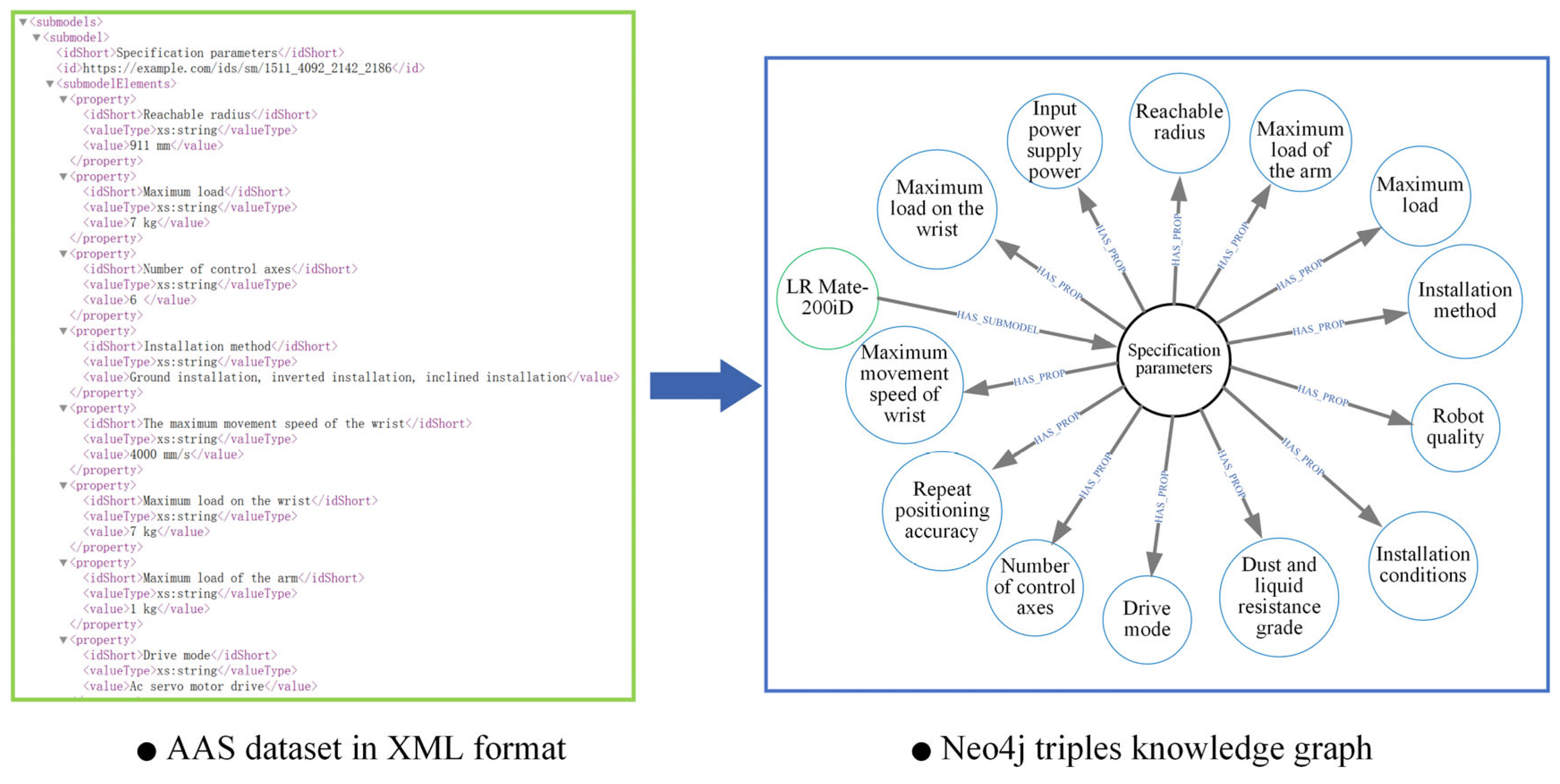
4.2. From AAS Repository to Knowledge Graph

An ontology is a description providing a shared understating of a given domain and facilitates the reuse of knowledge [83]. The AAS is not only a descriptive model but also represents and specifies the valid ingredients of a model. Namely, the AAS built with the domain-specific meta-modeling method is integrated with the ontology concepts. Using XML for the AAS ensures compatibility with other data exchange protocols and industry standards. As illustrated in Figure 5, using a Python script, libraries like ‘xml.etree. ElementTree’ are employed to parse the XML data exported from the AAS and extract key elements.
Specifically, the script extracts the submodel and property nodes from the XML files, which represent the entities of the assets. Each asset’s unique identifier is treated as an entity in the knowledge graph, creating a standardized digital representation. During the parsing process, the script also extracts RelationshipElements, which include the start and end points of relationships as well as the relationship type. These relationship elements represent the physical or data dependencies between the assets and form the edges in the knowledge graph. By analyzing the logical connections between assets, the interconnectivity of the assets is transformed into structured relationship information in the graph, enriching the semantic content of the knowledge graph. The extracted entities and relationships are mapped as triples and stored in a graph database, such as Neo4j. In addition, Neo4j’s graphical visualization capabilities allow the knowledge graph to be presented in an intuitive way, enabling users to interact dynamically with the assets and relationships. This facilitates deeper analysis and enhances the intelligent decision-making process.

4.3. From LLM to Knowledge Graph

Mining the semantic information of the AAS only to establish a knowledge base not effectively drives the generation of a comprehensive workshop facility layout, and a background knowledge base or an expert knowledge base aligned with task requirements is essential. In this context, pre-trained large language models can be employed to construct or refine this background knowledge map, specifically tailored for layout tasks. As illustrated in Figure 6, utilizing LLMs such as ChatGPT (https://openai.com/index/chatgpt/, accessed on 16 May 2025), structured prompts can streamline the design process for facility layout planning in smart factories [84]. This prompt guides planners to identify critical components, including machinery, workstations, and storage areas, while also considering workflows, spatial requirements, and future scalability [85,86,87]. Subsequently, the relevant shop-floor layout knowledge may be represented in XML or JSON format, detailing the dimensions and locations of various elements alongside a workflow sequence that encompasses material receipt through to finished-product storage. Furthermore, graph databases such as Neo4j offer an effective means of modeling the relationships between various shop-floor components, facilitating the efficient querying of operational connections.
Table 2 lists the definitions of the common relationships. Within Neo4j, layout knowledge can be structured as nodes representing distinct elements, such as CNC machines and assembly stations, alongside the relationships that depict the processes involved, thereby enhancing both clarity and utility in layout design. This integrative approach harnesses advanced technologies and methodologies to optimize facility layouts, fostering efficiency and adaptability in contemporary manufacturing environments. A hybrid knowledge base is created to addresses the limitations of the AAS by combining AAS data with the insights from LLMs, incorporating real-world scenarios, best practices, and contextual frameworks to enrich the overall knowledge.

4.4. Layout Reasoning Based on ConvE Model

The mixed knowledge map of the workshop layout design is established based on the AAS and large language model. The knowledge graph constructs the relationships between various entities (such as equipment, workstations, materials, operators, and production tasks), such as proximity, dependence, material flow, and task execution. Because there are only positive examples in the knowledge map, in order to solve the problem of data sparsity in ConvE model training (that is, the frequency of some relationships and entities is low), negative samples (that is, wrong triples) can be generated to help the model learn how to distinguish real triples from wrong triples. Usually, negative samples are generated in two ways: replacing the head entity or the tail entity; randomly replacing an entity in the triplet to generate an incorrect triplet. To randomly select irrelevant relationships, correct entity pairs are combined with irrelevant relationships to generate untrue triples. Negative sampling is used to generate wrong triples and then used to train the ConvE model together with positive sampling. Therefore, knowledge graph completion (KGC) makes it possible to predict the possible relationships between entities and promote the optimization of the layout by suggesting the most effective spatial arrangement based on the predicted dependence and proximity.
The representation-learning-based knowledge graph completion methods include tensor factorization, translation models, deep learning, and language model fusion [88]. ConvE was the first model to use the convolutional neural network (CNN) architecture for KGC [89]. As illustrated in Figure 7, ConvE first reshapes the head-entity embedding and relation embedding, concatenating them into an input matrix for the 2D convolution layer, which then returns a feature map tensor [90]. The most important characteristic of ConvE is that the score it produces is defined by an embedded 2D convolution. To train the ConvE model for link prediction, the entity and relationship embedding are initialized and optimized using a convolutional neural network (CNN) architecture. The input to the model consists of triplets, where the embeddings of the head entity and relation are concatenated and passed through convolutional layers to extract local interaction features. These features are then processed by fully connected layers to compute a score that indicates the likelihood of a valid relationship between the head and tail entities. The model is trained using binary cross-entropy loss and optimized via the Adam optimizer, minimizing the error between the predicted and actual triplets.
Once trained, the model can predict missing links by calculating the likelihood of a tail entity, given a head entity and a relation, ranking potential tail entities by their predicted scores. This link prediction process facilitates the optimization of workshop layouts by identifying the optimal spatial arrangements based on the predicted relationships, enhancing operational efficiency and workflow design. The link prediction performance of the ConvE model is evaluated using several metrics, including average rank, mean reciprocal rank (MRR), and hits@k, which assess the accuracy of the predicted relationships. These metrics evaluate the ranking quality of the predicted tail entities by comparing their predicted scores with the actual triple. Lower ranks and a higher MRR indicate better prediction accuracy. Additionally, hits@k measures the model’s ability to rank the correct tail entity within the top k predictions, offering a practical assessment of its effectiveness in real-world applications. Through these evaluation metrics, ConvE’s ability to accurately predict relationships and dependencies is confirmed, ensuring its reliability and potential to optimize spatial layouts, improving the design of production systems and overall workflow efficiency.

4.5. Layout Optimization

Layout optimization is typically a multi-objective problem that requires balancing several factors, such as logistics costs, equipment interdependence, and safety constraints. In addition to assessing logistics costs and constraint violations, it is beneficial to consider additional metrics such as production efficiency, energy consumption, and equipment failure rates. These indicators provide a more comprehensive evaluation of the optimization solution’s overall effectiveness. To achieve an optimal layout, an intelligent optimization algorithm, informed by the knowledge graph, can be employed. In this context, the equipment neighborhood score predicted by the ConvE model serves as one of the key constraints in the optimization process. The algorithm can dynamically adjust equipment positions based on these scores and practical constraints, ultimately determining the most efficient and effective workshop layout. Furthermore, incorporating graphical interfaces, such as 3D layout visualization and simulations, can enhance the presentation of the workshop layout optimization results. This allows decisionmakers to not only analyze the optimization outcomes through data analysis but also visually observe the improved layout design through interactive tools.

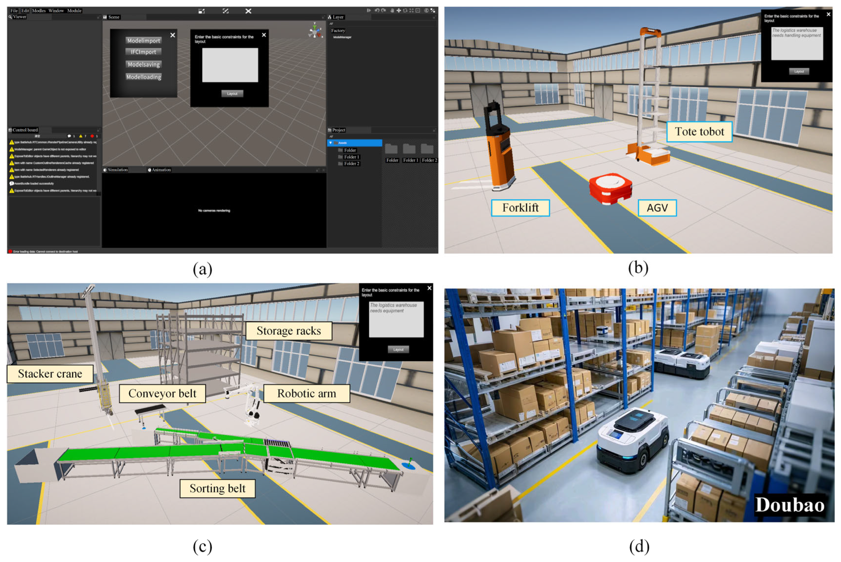
4.6. System Development and Testing

The FLD 4.0 prototype system integrates Flask, Neo4j, and Unity to provide an advanced solution for optimizing and visualizing facility layouts. The Neo4j graph database stores the relationships between machines, workstations, and other facility components, facilitating flexible querying and layout optimization. On the front end, Unity serves as a 3D visualization platform, allowing users to interact with and view the layout in real time. Flask functions as the back end, managing user requests, interacting with the Neo4j database, and executing optimization algorithms. Flask-RESTful or Blueprints is employed to modularize the application programming interface (API) endpoints for user management, layout optimization, and Neo4j interactions. Unity communicates with Flask via Flask-SocketIO, retrieving layout data and rendering them as 3D objects within the virtual environment. This setup enables users to dynamically modify and optimize the facility layout while Unity updates the 3D scene in real time. The system can be deployed on cloud platforms for easy access, and Unity offers flexible deployment options, including standalone executables or WebGL for browser-based interactions.
Figure 8 demonstrates a basic case of generating a layout of a logistics storage workshop. By inputting the text of the layout requirements in the system’s GUI (Figure 8a), the system produces editable 3D layout scenes, as shown in Figure 8b,c. This process allows for quick iterations and the visual representation of complex design concepts, enabling users to adjust and refine the layout based on real-time feedback. Recently, artificial-intelligence-generated content (AIGC) has been gaining significant attention and experiencing exponential growth [90]. The AIGC platform Doubao (https://www.doubao.com/chat/, accessed on 16 May 2025) generates a visual scene image based on the same prompts. Undoubtedly, the generative-AI-enabled facility layout design is no longer a dream but is now feasible. As the system continues to improve, the potential for AI-powered facility layout design (FLD 4.0) will be immense. It will likely revolutionize how layouts are planned and optimized, offering faster, more efficient, and creative solutions that reduce human error and increase productivity.

5. Conclusions

General AI-generated layout design (such as for games, videos, or slides) primarily prioritizes aesthetic and visual accuracy. In contrast, AI-driven facility layout generation is pragmatically focused, transforming vague intentions and concepts into highly interconnected and efficiently functioning workshops. This process involves the complex integration of diverse multi-domain semantics, heterogeneous information, and data, while also considering intentional and conditional real-world constraints. These constraints include factors such as functionality, efficiency, security, spatial requirements, cost-effectiveness, and adaptability to dynamic disturbances. Although the emerging Industry 4.0 paradigm, supported by powerful enabling technologies, offers the potential for AI-driven facility layout generation, the complexity of its full implementation still faces significant challenges, such as involving hundreds of domain standards and complex cyber–physical system modeling.
Given the above challenges, this exploratory research was devoted to promoting the urgent need for a shift in the facility layout design paradigm. This research traced the evolution of FLD through three historical paradigms: manual methods, operations research, and simulation-based engineering, culminating in the proposed novel paradigm—generative-AI-enabled facility layout generation. Furthermore, a reference architecture for FLD 4.0 was presented, supporting end-to-end layout generation. This architecture features a 3D visualization engine, AI-driven generation, and real-time digital twins. Building upon the foundational principles of Industry 4.0 and the significance of the AAS, a domain-specific hybrid knowledge graph is constructed by parsing AAS meta-models and enriching it with large language models. This knowledge graph captures complex relationships to guide layout generation. In addition, the convolutional knowledge graph embedding method is applied for link prediction, and the predicted link scores identify the recommended layout. A prototype system is developed, and the testing results demonstrate the system’s end-to-end generation ability from requirement-driven contextual prompts. The system significantly reduces the complexities of modeling, integration, and optimization. The platform can greatly shorten the cycle of industrial workshop design as well as reduce the complexity of layout initialization design and is beneficial to the integration of artificial intelligence and human intelligence.
Despite the promising advancements produced by FLD 4.0, there are still several limitations that must be addressed to fully unlock its potential in real-world applications.
First, the system’s reliance on large, heterogeneous data sources—such as AAS metadata and LLMs—introduces challenges related to data quality, consistency, and integrity. As the prototype system does not yet fully integrate simulation-generated data, human-centered ergonomics data, and real-time data from the Internet of Things, the process of combining such diverse datasets into a unified and robust knowledge graph remains a complex long-term task. This integration process still demands significant professional labor and expertise to ensure data reliability. In the future, systems will incorporate multi-agent reinforcement learning, enabling agents to learn decision making through interaction with an AI-driven simulated environment. This will be facilitated by algorithms such as Q learning and deep Q networks (DQNs), which are widely employed in this domain [91].
Furthermore, while the ConvE-based prediction process is effective, it requires further refinement to better generate dynamic, large-scale industrial layouts. The system’s ability to adapt to unforeseen disruptions is insufficient. Moreover, the scalability, adaptability, and robustness of the system in large-scale facilities with numerous interacting components have yet to be fully explored. Future research should prioritize enhancing data and semantic model integration technologies, technically completing service-oriented architecture, optimizing AI-driven algorithms for real-time adaptability, and ensuring that the system can scale efficiently without compromising performance.
Additionally, advances in human–machine collaboration are crucial to improving the interpretability and flexibility of AI-driven layouts, allowing facility managers to make more intuitive, data-informed decisions. Addressing these challenges will require a multidisciplinary approach, combining artificial intelligence, industrial engineering, and systems modeling to push the boundaries of facility layout design.

Author Contributions

F.H.: writing—review and editing, writing—original draft, visualization, supervision, resources, project administration, methodology, investigation, funding acquisition, formal analysis, conceptualization. C.W.: visualization, validation, software, investigation, data curation. X.W.: software, investigation. All authors have read and agreed to the published version of the manuscript.

Funding

This project was funded by the National Key Research and Development Program of China, grant number 2023YFB3406300.

Institutional Review Board Statement

Not applicable.

Informed Consent Statement

Not applicable.

Data Availability Statement

All data generated or analyzed during this study are included in this article.

Conflicts of Interest

The authors declare no conflicts of interest.

Nomenclature

AASAsset Administration Shell
AGVAutomated Guided Vehicle
AHPAnalytic Hierarchy Process
AIArtificial Intelligence
AIGCAI-Generated Content
APIApplication Programming Interface
CADComputer-Aided Design
CNCComputer Numerical Control
CNNConvolutional Neural Network
ConvEConvolutional Knowledge Graph Embedding
CPSsCyber–Physical Systems
DQNsDeep Q Networks
DTDigital Twin
FLDFacility Layout Design
FLD 1.0Facility Layout Design Paradigm Based on Experience
FLD 2.0Facility Layout Design Paradigm Based on Optimization
FLD 3.0Facility Layout Design Paradigm Based on Simulation
FLD 4.0Facility Layout Design Paradigm Based on Artificial Intelligence
GDGenerative Design
GUIsGraphical User Interfaces
Industry 4.0 The Fourth Industrial Revolution
IoTInternet of Things
JSONJavaScript Object Notation
KGCKnowledge Graph Completion
LLMsLarge Language Models
MADMMulti-Attribute Decision Making
MBSEModel-Based Systems Engineering
MQTT Message Queuing Telemetry Transport
MRRMean Reciprocal Rank
NLPNatural Language Processing
NP-HardNon-deterministic Polynomial-Hard
OPC UAOpen Platform Communications Unified Architecture
OROperations Research
RAMI 4.0 Reference Architecture Model for Industry 4.0
SLPSystematic Layout Planning
TOPSISTechnique for Order Preference by Similarity to Ideal Solution
WSMWeighted Sum Model
XMLeXtensible Markup Language

References

  1. Fisher, E.L. An AI-based methodology for factory design. AI Mag. 1986, 7, 72. [Google Scholar] [CrossRef]
  2. Hosseini-Nasab, H.; Fereidouni, S.; Fatemi Ghomi, S.M.T.; Fakhrzad, M.B. Classification of facility layout problems: A review study. Int. J. Adv. Manuf. Technol. 2018, 94, 957–977. [Google Scholar] [CrossRef]
  3. Constantinescu, C.; Westkämper, E. A reference model for factory engineering and design. In Proceedings of the 6th CIRP-Sponsored International Conference on Digital Enterprise Technology; Springer: Berlin/Heidelberg, Germany, 2010; pp. 1551–1564. [Google Scholar] [CrossRef]
  4. Monga, R.; Khurana, V. Facility layout planning: A review. Int. J. Innov. Res. Sci. Eng. Technol. 2015, 4, 976–980. [Google Scholar]
  5. Okpala, C.C.; Chukwumuanya, O. Plant layouts’analysis and design. Int. J. Eng. Adv. Technol. 2016, 201, 206. [Google Scholar]
  6. Smith, J.M.G. Dilemmas in factory design: Paradox and paradigm. In Stochastic Modeling of Manufacturing Systems: Advances in Design, Performance Evaluation, and Control Issues; Springer: Berlin/Heidelberg, Germany, 2006; pp. 3–25. [Google Scholar] [CrossRef]
  7. Lin, L.C.; Sharp, G.P. Quantitative and qualitative indices for the plant layout evaluation problem. Eur. J. Oper. Res. 1999, 116, 100–117. [Google Scholar] [CrossRef]
  8. Heinbach, B.; Burggräf, P.; Wagner, J. Deep reinforcement learning for layout planning–An MDP-based approach for the facility layout problem. Manuf. Lett. 2023, 38, 40–43. [Google Scholar] [CrossRef]
  9. Heinbach, B.; Burggräf, P.; Wagner, J. Gym-flp: A Python Package for Training Reinforcement Learning Algorithms on Facility Layout Problems. Oper. Res. Forum 2024, 5, 20. [Google Scholar] [CrossRef]
  10. Barbosa-Póvoa, A.P.; Mateus, R.; Novais, A.Q. Optimal design and layout of industrial facilities: A simultaneous approach. Ind. Eng. Chem. Res. 2002, 41, 3601–3609. [Google Scholar] [CrossRef]
  11. Süße, M.; Putz, M. Generative design in factory layout planning. Procedia CIRP 2021, 99, 9–14. [Google Scholar] [CrossRef]
  12. Anjos, M.F.; Vieira, M.V.C. Mathematical optimization approaches for facility layout problems: The state-of-the-art and future research directions. Eur. J. Oper. Res. 2017, 261, 1–16. [Google Scholar] [CrossRef]
  13. Sulaiman, S.S.; Jancy, P.L.; Muthiah, A.; Janakiraman, V.; Gnanaraj, S.J.P. An evolutionary optimal green layout design for a production facility by simulated annealing algorithm. Mater. Today Proc. 2021, 47, 4423–4430. [Google Scholar] [CrossRef]
  14. Klar, M.; Langlotz, P.; Aurich, J.C. A framework for automated multiobjective factory layout planning using reinforcement learning. Procedia CIRP 2022, 112, 555–560. [Google Scholar] [CrossRef]
  15. Besbes, M.; Zolghadri, M.; Affonso, R.C.; Masmoudi, F.; Haddar, M. 3D facility layout problem. J. Intell. Manuf. 2021, 32, 1065–1090. [Google Scholar] [CrossRef]
  16. Kulturel-Konak, S. Approaches to uncertainties in facility layout problems: Perspectives at the beginning of the 21 st Century. J. Intell. Manuf. 2007, 18, 273–284. [Google Scholar] [CrossRef]
  17. Pérez-Gosende, P.; Mula, J.; Díaz-Madroñero, M. A bottom-up multi-objective optimisation approach to dynamic facility layout planning. Int. J. Prod. Res. 2024, 62, 626–643. [Google Scholar] [CrossRef]
  18. Benjaafar, S.; Heragu, S.S.; Irani, S.A. Next generation factory layouts: Research challenges and recent progress. Interfaces 2002, 32, 58–76. [Google Scholar] [CrossRef]
  19. Zha, S.; Guo, Y.; Huang, S.; Wang, F.; Huang, X. Robust facility layout design under uncertain product demands. Procedia CIRP 2017, 63, 354–359. [Google Scholar] [CrossRef]
  20. Zuniga, E.R.; Moris, M.U.; Syberfeldt, A.; Fathi, M.; Rubio-Romero, J.C. A simulation-based optimization methodology for facility layout design in manufacturing. IEEE Access 2020, 8, 163818–163828. [Google Scholar] [CrossRef]
  21. Naranje, V.; Reddy, P.V.; Sharma, B.K. Optimization of factory layout design using simulation tool. In Proceedings of the 2019 IEEE 6th International Conference on Industrial Engineering and Applications (ICIEA), Tokyo, Japan, 12–15 April 2019; pp. 193–197. [Google Scholar] [CrossRef]
  22. Zhang, Z.; Wang, X.; Wang, X.; Cui, F.; Cheng, H. A simulation-based approach for plant layout design and production planning. J. Ambient. Intell. Humaniz. Comput. 2019, 10, 1217–1230. [Google Scholar] [CrossRef]
  23. Garcia, E.F.; Zúñiga, E.R.; Bruch, J.; Moris, M.U.; Syberfeldt, A. Simulation-based optimization for facility layout design in conditions of high uncertainty. Procedia CIRP 2018, 72, 334–339. [Google Scholar] [CrossRef]
  24. Negahban, A.; Smith, J.S. Simulation for manufacturing system design and operation: Literature review and analysis. J. Manuf. Syst. 2014, 33, 241–261. [Google Scholar] [CrossRef]
  25. Jefroy, N.; Azarian, M.; Yu, H. The Application of Simulation in Facility Layout Design of an Industry 4.0 Factory. In International Workshop of Advanced Manufacturing and Automation; Springer Nature: Singapore, 2023; pp. 89–99. [Google Scholar] [CrossRef]
  26. Cañas, H.; Mula, J.; Díaz-Madroñero, M.; Campuzano-Bolarín, F. Implementing industry 4.0 principles. Comput. Ind. Eng. 2021, 158, 107379. [Google Scholar] [CrossRef]
  27. Suleiman, Z.; Shaikholla, S.; Dikhanbayeva, D.; Shehab, E.; Turkyilmaz, A. Industry 4.0: Clustering of concepts and characteristics. Cogent Eng. 2022, 9, 2034264. [Google Scholar] [CrossRef]
  28. Aheleroff, S.; Huang, H.; Xu, X.; Zhong, R.Y. Toward sustainability and resilience with Industry 4.0 and Industry 5.0. Front. Manuf. Technol. 2022, 2, 951643. [Google Scholar] [CrossRef]
  29. Pereira, A.C.; Romero, F. A review of the meanings and the implications of the Industry 4.0 concept. Procedia Manuf. 2017, 13, 1206–1214. [Google Scholar] [CrossRef]
  30. Gurjanov, A.V.; A Zakoldaev, D.; Shukalov, A.V.; O Zharinov, I. Formation principles of digital twins of Cyber-Physical Systems in the smart factories of Industry 4.0. In IOP Conference Series: Materials Science and Engineering; IOP Publishing Ltd.: Volgograd, Russia, 2019; Volume 483, p. 012070. [Google Scholar] [CrossRef]
  31. Lin, W.D.; Low, M.Y.H. Concept design of a system architecture for a manufacturing cyber-physical digital twin system. In Proceedings of the 2020 IEEE International Conference on Industrial Engineering and Engineering Management (IEEM), Singapore, 14–17 December 2020; pp. 1320–1324. [Google Scholar] [CrossRef]
  32. Zhang, H.; Zhang, G.; Yan, Q. Digital twin-driven cyber-physical production system towards smart shop-floor. J. Ambient. Intell. Humaniz. Comput. 2019, 10, 4439–4453. [Google Scholar] [CrossRef]
  33. Hu, F. Mutual information-enhanced digital twin promotes vision-guided robotic grasping. Adv. Eng. Inform. 2022, 52, 101562. [Google Scholar] [CrossRef]
  34. Hu, F.; Wang, W.; Zhou, J. Petri nets-based digital twin drives dual-arm cooperative manipulation. Comput. Ind. 2023, 147, 103880. [Google Scholar] [CrossRef]
  35. Hu, F. Digital twin-driven reconfigurable fixturing optimization for trimming operation of aircraft skins. Aerospace 2022, 9, 154. [Google Scholar] [CrossRef]
  36. Hu, F.; Qiu, X.; Jing, G.; Tang, J.; Zhu, Y. Digital twin-based decision making paradigm of raise boring method. J. Intell. Manuf. 2023, 34, 2387–2405. [Google Scholar] [CrossRef]
  37. Burggräf, P.; Adlon, T.; Schäfer, N. Towards Digital-Twin-Driven Factory Planning–A Systematic Review. Procedia CIRP 2024, 126, 248–253. [Google Scholar] [CrossRef]
  38. Lind, A.; Hanson, L.; Högberg, D.; Lämkull, D.; Mårtensson, P.; Syberfeldt, A. Digital support for rules and regulations when planning and designing factory layouts. Procedia CIRP 2023, 120, 1445–1450. [Google Scholar] [CrossRef]
  39. Büscher, C.; Meisen, T.; Schilberg, D.; Jeschke, S. VPI-FP: An integrative information system for factory planning. Int. J. Prod. Res. 2016, 54, 2215–2226. [Google Scholar] [CrossRef]
  40. Wang, W.Y.; Zhang, S.; Li, G.; Lu, J.; Ren, Y.; Wang, X.; Gao, X.; Su, Y.; Song, H.; Li, J. Artificial intelligence enabled smart design and manufacturing of advanced materials: The endless Frontier in AI+ era. Mater. Genome Eng. Adv. 2024, 2, e56. [Google Scholar] [CrossRef]
  41. Coelho, P.; Bessa, C.; Landeck, J.; Silva, C. Industry 5.0: The arising of a concept. Procedia Comput. Sci. 2023, 217, 1137–1144. [Google Scholar] [CrossRef]
  42. Suhardini, D.; Septiani, W.; Fauziah, S. Design and simulation plant layout using systematic layout planning. In IOP Conference Series: Materials Science and Engineering; IOP Publishing Ltd.: Tanjung Pandan, Indonesia, 2017; Volume 277, p. 012051. [Google Scholar] [CrossRef]
  43. Salins, S.S.; Zaidi, S.A.R.; Deepak, D.; Sachidananda, H.K. Design of an improved layout for a steel processing facility using SLP and lean Manufacturing techniques. Int. J. Interact. Des. Manuf. (IJIDeM) 2024, 18, 3827–3848. [Google Scholar] [CrossRef]
  44. Sharma, P.; Singhal, S. Implementation of fuzzy TOPSIS methodology in selection of procedural approach for facility layout planning. Int. J. Adv. Manuf. Technol. 2017, 88, 1485–1493. [Google Scholar] [CrossRef]
  45. Singh, S.P.; Singh, V.K. Three-level AHP-based heuristic approach for a multi-objective facility layout problem. Int. J. Prod. Res. 2011, 49, 1105–1125. [Google Scholar] [CrossRef]
  46. Tubaileh, A.; Siam, J. Single and multi-row layout design for flexible manufacturing systems. Int. J. Comput. Integr. Manuf. 2017, 30, 1316–1330. [Google Scholar] [CrossRef]
  47. Chen, C.; Tiong, L.K. Using queuing theory and simulated annealing to design the facility layout in an AGV-based modular manufacturing system. Int. J. Prod. Res. 2019, 57, 5538–5555. [Google Scholar] [CrossRef]
  48. Burggräf, P.; Adlon, T.; Lehde, N.; Lindholm, N. Uncovering the behaviour of facility layout problem solutions in relation to factory design applications. Procedia CIRP 2024, 126, 93–98. [Google Scholar] [CrossRef]
  49. Gao, T.; Wang, L.; Song, W.; Cheng, Y.; Zuo, Y.; Xiang, F.; Zhang, H.; Tao, F. Ten industrial software towards smart manufacturing. J. Manuf. Syst. 2025, 79, 255–285. [Google Scholar] [CrossRef]
  50. Akar, N.; Turgay, S. Optimizing Cellular Manufacturing Facility Layout Design through Digital Twin Simulation: A Case Study. Ind. Eng. Innov. Manag. 2023, 6, 1–12. [Google Scholar] [CrossRef]
  51. Jiang, S.; Li, L.; Deng, K. Optimization and Simulation of Production Line Layout Based on Plant Simulation. In Proceedings of the 2022 IEEE 5th International Conference on Automation, Electronics and Electrical Engineering (AUTEEE), Shenyang, China, 18–20 November 2022; pp. 180–185. [Google Scholar] [CrossRef]
  52. Centobelli, P.; Cerchione, R.; Murino, T. Layout and material flow optimization in digital factory. Int. J. Simul. Model. 2016, 15, 223–235. [Google Scholar] [CrossRef]
  53. Choi, H.; Yu, S.; Lee, D.; Noh, S.D.; Ji, S.; Kim, H.; Yoon, H.; Kwon, M.; Han, J. Optimization of the Factory Layout and Production Flow Using Production-Simulation-Based Reinforcement Learning. Machines 2024, 12, 390. [Google Scholar] [CrossRef]
  54. Mahmood, K.; Otto, T.; Chakraborty, A. Layout planning and analysis of a Flexible Manufacturing System based on 3D Simulation and Virtual Reality. Procedia CIRP 2023, 120, 201–206. [Google Scholar] [CrossRef]
  55. Gyulai, D.; Szaller, Á.; Viharos, Z.J. Simulation-based flexible layout planning considering stochastic effects. Procedia CIRP 2016, 57, 177–182. [Google Scholar] [CrossRef]
  56. Xu, X. SLP-based technical plant layout planning and simulation analysis. In IOP Conference Series: Materials Science and Engineering; IOP Publishing Ltd.: Sanya, China, 2020; Volume 772, p. 012020. [Google Scholar] [CrossRef]
  57. Gabor, T.; Belzner, L.; Kiermeier, M.; Beck, M.T.; Neitz, A. A simulation-based architecture for smart cyber-physical systems. In Proceedings of the 2016 IEEE International Conference on Autonomic Computing (ICAC), Wuerzburg, Germany, 17–22 July 2016; pp. 374–379. [Google Scholar] [CrossRef]
  58. Hehenberger, P.; Vogel-Heuser, B.; Bradley, D.; Eynard, B.; Tomiyama, T.; Achiche, S. Design, modelling, simulation and integration of cyber physical systems: Methods and applications. Comput. Ind. 2016, 82, 273–289. [Google Scholar] [CrossRef]
  59. Falcone, A.; Garro, A. Distributed co-simulation of complex engineered systems by combining the high level architecture and functional mock-up interface. Simul. Model. Pract. Theory 2019, 97, 101967. [Google Scholar] [CrossRef]
  60. Benali, H.; Ben Saoud, N.B. Towards a component-based framework for interoperability and composability in Modeling and Simulation. Simulation 2011, 87, 133–148. [Google Scholar] [CrossRef]
  61. Peron, M.; Fragapane, G.; Sgarbossa, F.; Kay, M. Digital facility layout planning. Sustainability 2020, 12, 3349. [Google Scholar] [CrossRef]
  62. Lather, J.I.; Logan, T.; Renner, K.; Messner, J.I. Implementation and evaluation of generative layout options using the graph theoretical approach for a hospital layout problem. J. Comput. Civ. Eng. 2020, 34, 04020014. [Google Scholar] [CrossRef]
  63. Caneparo, L. Semantic knowledge in generation of 3D layouts for decision-making. Autom. Constr. 2022, 134, 104012. [Google Scholar] [CrossRef]
  64. Yao, Z.; Chen, Y.; Cui, J.; Zhang, S.; Li, S.; Hao, A. Conditional room layout generation based on graph neural networks. Comput. Graph. 2024, 122, 103971. [Google Scholar] [CrossRef]
  65. Shi, Y.; Shang, M.; Qi, Z. Intelligent layout generation based on deep generative models: A comprehensive survey. Inf. Fusion 2023, 100, 101940. [Google Scholar] [CrossRef]
  66. Cohen, Y.; Aperstein, Y. Generative Shopfloor Layout Design: Challenges and Proposed Modelling Approach. IFAC-PapersOnLine 2024, 58, 748–753. [Google Scholar] [CrossRef]
  67. Pawletta, T.; Pascheka, D.; Schmidt, A.; Pawletta, S. Ontology-Assisted System Modeling and Simulation within MATLAB/Simulink. Simul. Notes Eur. 2014, 24, 59–68. [Google Scholar] [CrossRef]
  68. Arnarson, H.; Yu, H.; Olavsbråten, M.M.; Bremdal, B.A.; Solvang, B. Towards smart layout design for a reconfigurable manufacturing system. J. Manuf. Syst. 2023, 68, 354–367. [Google Scholar] [CrossRef]
  69. Liu, X.; Qiu, C.; Shi, J.; Huang, J.; Zhu, C.; Ni, Z.; Zhu, M.; Liu, T. A digital twin modeling method for production resources of shop floor. Int. J. Adv. Manuf. Technol. 2023, 128, 743–761. [Google Scholar] [CrossRef]
  70. Lee, J.; Azamfar, M.; Bagheri, B. A unified digital twin framework for shop floor design in industry 4.0 manufacturing systems. Manuf. Lett. 2021, 27, 87–91. [Google Scholar] [CrossRef]
  71. Cloutier, R.; Muller, G.; Verma, D.; Nilchiani, R.; Hole, E.; Bone, M. The concept of reference architectures. Syst. Eng. 2010, 13, 14–27. [Google Scholar] [CrossRef]
  72. Nakagawa, E.Y.; Antonino, P.O.; Schnicke, F.; Capilla, R.; Kuhn, T.; Liggesmeyer, P. Industry 4.0 reference architectures: State of the art and future trends. Comput. Ind. Eng. 2021, 156, 107241. [Google Scholar] [CrossRef]
  73. Burns, T.; Cosgrove, J.; Doyle, F. A review of Interoperability Standards for Industry 4.0. Procedia Manuf. 2019, 38, 646–653. [Google Scholar] [CrossRef]
  74. Madni, A.M.; Sievers, M. System of systems integration: Key considerations and challenges. Syst. Eng. 2014, 17, 330–347. [Google Scholar] [CrossRef]
  75. Wenger, M.; Zoitl, A.; Müller, T. Connecting PLCs with their asset administration shell for automatic device configuration. In Proceedings of the 2018 IEEE 16th International Conference on Industrial Informatics (INDIN), Porto, Portugal, 18–20 July 2018; pp. 74–79. [Google Scholar] [CrossRef]
  76. Pérez-Gosende, P.; Mula, J.; Díaz-Madroñero, M. Facility layout planning. An extended literature review. Int. J. Prod. Res. 2021, 59, 3777–3816. [Google Scholar] [CrossRef]
  77. Fuchs, J.; Schmidt, J.; Franke, J.; Rehman, K.; Sauer, M.; Karnouskos, S. I4. 0-compliant integration of assets utilizing the Asset Administration Shell. In Proceedings of the 2019 24th IEEE International Conference on Emerging Technologies and Factory Automation (ETFA), Zaragoza, Spain, 10–13 September 2019; pp. 1243–1247. [Google Scholar] [CrossRef]
  78. Platenius-Mohr, M.; Malakuti, S.; Grüner, S.; Goldschmidt, T. Interoperable digital twins in IIoT systems by transformation of information models: A case study with asset administration shell. In Proceedings of the 9th International Conference on the Internet of Things, Bilbao, Spain, 22–25 October 2019; pp. 1–8. [Google Scholar] [CrossRef]
  79. Tian, L.; Zhou, X.; Wu, Y.-P.; Zhou, W.-T.; Zhang, J.-H.; Zhang, T.-S. Knowledge graph and knowledge reasoning: A systematic review. J. Electron. Sci. Technol. 2022, 20, 100159. [Google Scholar] [CrossRef]
  80. Wang, M.; Qiu, L.; Wang, X. A survey on knowledge graph embeddings for link prediction. Symmetry 2021, 13, 485. [Google Scholar] [CrossRef]
  81. Aßmann, U.; Zschaler, S.; Wagner, G. Ontologies, Meta-models, and the Model-Driven Paradigm. In Ontologies for Software Engineering and Software Technology; Calero, C., Ruiz, F., Piattini, M., Eds.; Springer: Berlin/Heidelberg, Germany, 2006; pp. 249–273. [Google Scholar] [CrossRef]
  82. Dettmers, T.; Minervini, P.; Stenetorp, P.; Riedel, S. Convolutional 2d knowledge graph embeddings. Proc. AAAI Conf. Artif. Intell. 2018, 32, 1811–1818. [Google Scholar] [CrossRef]
  83. Yang, X.; Liu, X.; Zhang, H.; Fu, L.; Yu, Y. An ontology-based shop-floor digital twin configuration approach. Procedia CIRP 2023, 120, 326–331. [Google Scholar] [CrossRef]
  84. Xia, Y.; Xiao, Z.; Jazdi, N.; Weyrich, M. Generation of Asset Administration Shell with Large Language Model Agents: Towards Semantic Interoperability in Digital Twins in the Context of Industry 4.0. IEEE Access 2024, 12, 84863–84877. [Google Scholar] [CrossRef]
  85. Miny, T.; Thies, M.; Lukic, L.; Käbisch, S.; Oladipupo, K.; Diedrich, C.; Kleinert, T. Overview and Comparison of Asset Information Model Standards. IEEE Access 2023, 11, 99189–99221. [Google Scholar] [CrossRef]
  86. Drath, R.; Rentschler, M.; Hoffmeister, M. The automationml component description in the context of the asset administration shell. In Proceedings of the 2019 24th IEEE International Conference on Emerging Technologies and Factory Automation (ETFA), Zaragoza, Spain, 10–13 September 2019; pp. 1278–1281. [Google Scholar] [CrossRef]
  87. Strakošová, S.; Novák, P.; Kadera, P. Product-Oriented Product-Process-Resource Asset Network and its Representation in AutomationML for Asset Administration Shell. In Proceedings of the 2024 IEEE 29th International Conference on Emerging Technologies and Factory Automation (ETFA), Padova, Italy, 10–13 September 2024; pp. 1–8. [Google Scholar] [CrossRef]
  88. Zamini, M.; Reza, H.; Rabiei, M. A review of knowledge graph completion. Information 2022, 13, 396. [Google Scholar] [CrossRef]
  89. Dai, Y.; Wang, S.; Xiong, N.N.; Guo, W. A survey on knowledge graph embedding: Approaches, applications and benchmarks. Electronics 2020, 9, 750. [Google Scholar] [CrossRef]
  90. Cao, Y.; Li, S.; Liu, Y.; Yan, Z.; Dai, Y.; Yu, P.; Sun, L. A survey of ai-generated content (aigc). ACM Comput. Surv. 2025, 57, 1–38. [Google Scholar] [CrossRef]
  91. Gao, R.X.; Krüger, J.; Merklein, M.; Möhring, H.-C.; Váncza, J. Artificial Intelligence in manufacturing: State of the art, perspectives, and future directions. CIRP Ann. 2024, 73, 723–749. [Google Scholar] [CrossRef]
Figure 1. Evolution of the facility layout planning methodologies.
Applsci 15 05697 g001
Figure 2. Reference architecture of facility layout design 4.0.
Applsci 15 05697 g002
Figure 3. Basic framework and semantic communication of Asset Administration Shell.
Applsci 15 05697 g003
Figure 4. AI-driven end-to-end generation of shop-floor facility layout.
Applsci 15 05697 g004
Figure 5. Asset Administration Shell-based knowledge mapping.
Applsci 15 05697 g005
Figure 6. Large language model-aided modeling of contextual layout knowledge.
Applsci 15 05697 g006
Figure 7. Schematic of convolutional knowledge map embedding.
Applsci 15 05697 g007
Figure 8. Generative-AI-enabled facility layout design software and testing case. (a) GUI of the platform; (b) generated 3D layout scene; (c) regenerated 3D layout scene; (d) a visualized scene generated by the text-to-image platform Doubao using the same prompt.
Applsci 15 05697 g008
Table 1. Systematic contrasts with the evolution of facility layout methods.
Design ParadigmsFLD 1.0FLD 2.0FLD 3.0FLD 4.0
Basic principlesRule-of-thumbOperations researchModel- and simulation-based systemsAI-based generation
Starting years1780s1960s2000s2020s
Industrial ageIndustry 1.0Industry 2.0Industry 3.0Industry 4.0
Adaptive scenesSimple productionAutomatic large-scale productionFlexible and agile productionIntelligent production
Main features
  • Relying on the experience of planners
  • Function-oriented
  • Static layout design
  • Mathematical optimization models (linear programming, integer programming)
  • Efficiency-oriented, reducing waste and cost
  • Quantitative analysis
  • Discrete event and continuous simulation
  • Dynamic visualization and predictive analysis
  • Virtual model optimization
  • AI algorithm generates layout autonomously.
  • Real-time data-driven dynamic adjustment
  • Industry 4.0-component-compliant
Limitations
  • Lack of accuracy and extensibility
  • Not adapted to complex production environment
  • Dependent on high-quality data
  • Model assumptions ignore realistic details
  • Lack of real-time data integration
  • Modeling is complex and time-consuming
  • High data-quality requirements
  • Difficulties in cross-domain system integration
  • End-to-end models and data integration
  • Semantic interoperability
  • Complex multi-scale digital twin modeling
Table 2. Basic relationships among the facility layout.
Type of RelationshipDescriptionExample
Spatial RelationshipsDescribes the physical location relationships between facilities, which directly affect the spatial efficiency of the layout.
AdjacentTo: Facilities placed next to each other for frequent interaction.Milling machines next to assembly lines to reduce material handling time.
NearTo: Facilities located close to one another for efficient logistics.Placing raw material storage areas near machining stations for easier replenishment.
FarFrom: Certain facilities must be placed at a distance from each other for safety or environmental reasons. High-temperature furnaces should be far from flammable chemical storage for safety.
Process RelationshipsBased on the dependency relationships in the production process, determining the sequence of facilities.
NextProcess: Facilities that depend on each other for input/output.Stamping machine output feeds into cleaning, then to coating.
ParallelProcess: Facilities that can operate simultaneously to enhance capacity.Multiple CNC machines placed together for parallel part processing.
Material Flow RelationshipsDescribes the movement requirements of materials or personnel between facilities.
TransportPath: There are frequent material handling paths between facilities (e.g., automated guided vehicle (AGV) routes).A straight AGV path needs to be reserved between the storage area and the assembly line.
HighFrequencyFlow: Material interactions between facilities are frequent, requiring prioritization to shorten the distance.Stamping and quality control areas placed near each other.
Constraint RelationshipsRelationships created by safety, environmental, or regulatory restrictions.
MinimumSafetyDistance: Some facilities must maintain a safe distance from others for safety.High-voltage equipment placed away from operational areas.
EnvironmentalConstraint: Facilities that are noisy or temperature-sensitive must be isolated.Noisy stamping workshops should be placed away from office areas.
Functional RelationshipsRelationships based on the complementarity or collaboration needs of facility functions.
SharesResource: Facilities requiring shared resources (e.g., electricity, cooling systems) should be placed close to reduce waste.Machines sharing a central cooling system placed near one another.
CollaboratesWith: Facilities that must work closely together should be located near each other.Robotic welding stations near manual adjustment tables for easier adjustments.
Dynamic RelationshipsConsiders flexibility in facility placement for optimal use of space and equipment.
MobileFacility: Some facilities can be moved based on demand to improve efficiency.AGV charging stations can be dynamically adjusted for better equipment utilization.
TemporaryAdjacent: Temporary layout adjustments are made to cope with production peaks. Additional storage areas placed near assembly lines during peak periods.
Hierarchical RelationshipsDescribes the subordinate or grouping relationships of the facilities in the layout.
ParentChild: A facility is a subunit of a certain functional module.An assembly line with sub-stations like tightening or inspection.
BelongsToZone: A facility belongs to a specific functional zone (e.g., clean area, heavy equipment area). Precision instruments placed in cleanroom zones for accuracy.
Disclaimer/Publisher’s Note: The statements, opinions and data contained in all publications are solely those of the individual author(s) and contributor(s) and not of MDPI and/or the editor(s). MDPI and/or the editor(s) disclaim responsibility for any injury to people or property resulting from any ideas, methods, instructions or products referred to in the content.

