Article

Customized Pediatric Hand EXoskeleton for Activities of Daily Living (PHEX): Design, Development, and Characterization of an Innovative Finger Module

Laboratory of Advanced Robotics and Human-Centred Technologies—CREO Lab, Università Campus Bio-Medico di Roma, Via Àlvaro Del Portillo 21, 00128 Rome, Italy
*
Author to whom correspondence should be addressed.
Appl. Sci. 2025, 15(10), 5694; https://doi.org/10.3390/app15105694
Submission received: 20 April 2025 / Revised: 15 May 2025 / Accepted: 16 May 2025 / Published: 20 May 2025
(This article belongs to the Special Issue Emerging Technologies for Assistive Robotics)

Abstract

:
Research on pediatric hand exoskeletons remains limited compared to that on devices for adults. This paper presents the design and experimental validation of a customizable pediatric finger module, part of a hand exoskeleton tailored to individual anatomical features. The module aims to assist finger flexion in children with mild spasticity during activities of daily living. A patient-specific design methodology was applied to the case of a 12-year-old child. The finger module integrates compliant dorsal structures and cable-driven transmission with rigid anchoring elements to balance flexibility and structural stability. Different geometries and thickness values were tested to optimize comfort and quantify mechanical performance. Additive manufacturing was adopted to enable rapid prototyping and easy replacement of parts. Tensile and bending tests were conducted to determine stiffness and cable travel. Results support the feasibility of the proposed finger module, offering empirical data for selection and sizing of the actuation system and paving the way for the advancement of new modular pediatric devices.

1. Introduction

The sensorimotor system plays a central role in childhood development. A growing body of research highlights how the acquisition of motor skills influences a broad range of developmental domains, extending well beyond motor function alone. Among the various motor abilities that emerge in early life, object manipulation is considered a key milestone, as it significantly enhances infants’ interaction with—and understanding of—the external environment [1]. However, the development of these skills can be substantially hindered by several pathological conditions that affect hand mobility [2]. These include neurological disorders, such as cerebral palsy (affecting approximately 1 in 500 live births), pediatric stroke (1.2 to 13 cases per 100,000 children annually), and Duchenne Muscular Dystrophy (approximately 1 in 5000 live male births), as well as traumatic injuries, which affect an estimated 691 per 100,000 children each year [3]. Such impairments have been consistently associated with reduced autonomy in Activities of Daily Living (ADLs), limiting independence and quality of life [2,3,4,5]. Recently, pediatric exoskeletons have gained attention for their potential to assist children with physical impairments, improve rehabilitation outcomes, and promote independence in daily activities [6]. A significant challenge in the design and fabrication of these devices lies in the widespread adoption of the one-size-fits-all approach, which often neglects the anatomical variability of individual users [7]. Even if this strategy can reduce manufacturing complexity and costs, it severely limits the applicability and effectiveness of the devices across the heterogeneos target population [6,8]. This limitation is particularly critical in the pediatric context, where hand morphology evolves significantly throughout growth. During the first 18 years of life, the hand—like the rest of the musculoskeletal system—undergoes progressive changes in bone structure, tendon alignment, muscular development, and joint configuration. An atlas of radiographs documenting this evolution in both male and female subjects from birth to adulthood is provided in [9]. Although individual variability exists, the most notable developmental changes occur in the phalanges rather than in the carpal bones [10]. In early childhood (0–7 years), carpal ossification progresses and phalangeal epiphyses begin to appear. Between ages 8 and 18, these epiphyses gradually fuse with their respective diaphyses, leading to the completion of skeletal maturation.
This study addresses the challenge of the custom design of a pediatric hand exoskeleton. It focuses on the design, development, and preliminary testing of a finger module tailored to the anatomical features of the final user. To test the proposed procedure, we used data collected from a 12-year-old volunteer and developed a module for the index finger. This choice allowed us to test the module that demands the greatest customization effort in terms of geometry, structural properties, and material selection. The primary goal of the device under development is to assist patients with mild to moderate spasticity (Modified Ashworth Scale 2 ) in performing fingers flexion movements during ADLs. Our work aims to offer insights on the interaction between design strategies, material properties, and additive manufacturing (AM) techniques, thereby contributing to the advancement of more effective, personalized, and accessible pediatric assistive technologies.

2. Materials and Methods

2.1. Analysis of Requirements

A preliminary review of the existing technical literature on pediatric hand exoskeleton design was performed to support the identification of key design requirements. The analysis included both research prototypes and commercial devices with the aim of identifying common functional objectives and key design strategies. Several aspects were considered: target medical conditions, development maturity, intended age group, actuation mechanisms, overall device architecture, assisted Degrees of Freedom (ADoFs), strategies for user intention detection, and fingers supported.
A Boolean query that deliberately restricted the search results to only those technical works addressing the design problem for pediatric application was defined: (“exoskeleton” OR “robotic exoskeleton” OR “powered exoskeleton” OR “wearable exoskeleton” OR “robotic device”) AND (“hand” OR “wrist” OR “fingers”) AND (“pediatric” OR “children” OR “infants” OR “adolescents”). A constraint was applied to restrict the occurrence of these terms to the title or abstract. The search yielded 16 studies. Following a screening process based on relevance, target population and application area, eight studies were retained. Table 1 provides an overview of the main characteristics, including the mechanical and functional attributes, thereby facilitating a comprehensive evaluation of the identified exoskeletons. In addition, it offers an assessment of the current stage of development.
Exoskeletons were divided into rehabilitative [11,13,14,20] and assistive [5,12,16,21] types, which are equally represented. The former aim to restore motor functions temporarily compromised by injury or disease, whereas the latter are primarily designed to support users in the home environment, particularly during ADLs [3]. Furthermore, a consistent distribution in the types of exoskeletons is observed across categories. The proportion of soft exoskeleton [14,20,21] and rigid exoskeleton [11,13,16] papers is balanced. Although rigid exoskeletons provide high-precision control and efficient force transmission, their bulk and the difficulty in accommodating joint misalignments have limited their applicability, particularly for pediatric users [23]. In contrast, soft exoskeletons offer advantages such as reduced weight and lower bulk, yet their compliant structures introduce significant control challenges. As a result, soft-rigid architectures [5,12], which combine rigid and soft components, have emerged as a promising alternative [24]. These systems offer a favorable trade-off, enabling lightweight designs while ensuring sufficient structural rigidity [25].
From a mechanical perspective, two critical parameters include the Degree of Actuation (DoA) and the type of transmission mechanism implemented. Fingers are usually numbered from 1 (thumb) to 5 (little finger). The proportion of devices providing assistance to fingers 1 through 5 [5,15] is comparable to that of devices assisting only fingers 1 to 3 [20,21], which is a pattern commonly used by children. Transmission can be grouped into five main categories that take into consideration the implemented type of energy transduction [23]: bladder (fluidic transmission and pneumatic transduction), cable on glove (flexible transmission and electric transduction), constrained sliding (flexible transmission and thermal transduction), coupled DOF (linkage transmission and electric transduction), and independent DOF (linkage transmission and electric transduction). The results of our analysis highlight evident heterogeneity in the type of transmissions adopted across existing systems. Notably, the percentage of bladder systems [14,15] and independent DOF systems [11] appears to be comparable. Both these approaches present notable limitations. Bladder-based systems, which rely on pneumatic transducers, tend to suffer from low portability due to the bulk of ancillary components such as air compressors [3,23]. Independent DOF systems, while offering high movement precision, require a larger number of actuators, resulting in high weight and volume [23]. In contrast, the categories of constrained sliding [5,12], coupled DOF [13,16], and cable on glove [20,21] appear to be more evenly distributed. Among these, cable-based transmission has seen growing adoption in recent years, due to the simple architecture, reduced bulkiness, and improved portability [3].
The assessment of design maturity adopted in this study is derived from [26] to simplify categorization. Specifically, four development stages were considered: (i) concept design (TRL 1–3); (ii) clinical trials (TRL 4–6); (iii) prototype (TRL 7); and (iv) commercial (TRL 8–9). This classification was proposed to provide a clearer understanding of both the technological maturity of each device and its expected performance in real-world environments. For ease of reference, the corresponding development stage is reported in the fourth column of Table 1). Only one rehabilitation device has reached the commercial stage [15], while a single assistive device was found to be in the clinical trial phase [5]. In the case study presented by Dittli et al. [17], the feasibility of home use of the pediatric robotic hand orthosis PEXO (see [5] in Table 1) was evaluated in a 13-year-old child with hand impairment following traumatic brain injury. After tailoring the device to the child’s needs and providing user training, the child and parent used the PEXO at home over two weeks, showing improved hand function and device acceptance without any safety issues. However, with few exceptions, hand exoskeletons for pediatric users remain underdeveloped, particularly regarding customization to individual patients. A key limitation is the frequent adaptation of designs derived from adult models [21], although such adaptations have demonstrated effectiveness in certain cases. Kuo et al. [27] demonstrated the feasibility and positive outcomes of integrating robot-assisted therapy with conventional rehabilitation in a pediatric stroke case, utilizing the Gloreha Sinfonia device—originally designed for adults and adapted for pediatric use—to enhance hand function and daily activity performance. Bressi et al. [28] reported similar benefits in a 10-year-old post-stroke patient, highlighting improvements in sensorimotor capabilities and quality of life through the combined use of Gloreha Sinfonia and traditional therapy. Another major challenge observed during the design process is that the interaction with children is inherently more complex than that with adult users [7,16]. This is due to the fact that children may struggle to follow precise instructions or remain in static positions. These aspects introduce additional constraints to user-centered development, and are currently being investigated through ongoing data collection during user interaction sessions. Moreover, device miniaturization is still an open issue to ensure functional efficacy and reduce overall weight, which are critical aspects when designing for children [2,7].
Children predominantly employ a three-finger approach when manipulating objects, as reported by Battraw et al. [29]. Four of the eight solutions summarized in Table 1 support fingers 1 to 3 and are classified as soft or soft-rigid systems [5,14,20,22]. Among these, two solutions implement cable-driven transmissions, which reduce the weight borne by the hand [20,22]. Based on these findings, and considering the common issue of mechanical misalignment in rigid-link parallel systems, the present study focuses on the development of a hand exoskeleton incorporating soft-rigid finger modules to support thumb flexion and opposition, as well as index and middle finger flexion, while ensuring passive extension of all involved joints. This system, referred to as the Pediatric Hand EXoskeleton (PHEX), adopts a cable-based transmission to simplify the mechanical architecture, reduce bulkiness, and improve portability. To ensure proper customization and effective torque transmission, the exoskeleton design requires a model of the user’s fingers based on the patient’s hand anthropometric features. To simplify interaction with pediatric users, only essential parameters are measured. In this work, hand length (HL) and phalanx diameters are obtained using a metric tape and a ring sizer, respectively, while phalanx lengths are estimated from HL through empirical scaling coefficients [30]. These measurements are needed to inform the design of the cable routing paths and the selection of component dimensions. Moreover, to promote consistent use and adherence among pediatric users, the device must consider non-functional requirements related to aesthetics and comfort. In this context, the design should be both visually appealing and ergonomically suitable to enhance user acceptance and long-term wearability [7].
Given the complexity and variability of hand movements in children, using a cable-driven transmission offers a significant advantage. Specifically, the absence of rigid constraints on the fingers during grasping allows for smooth and adaptive interaction with objects, thereby accommodating the natural movements of the pediatric hand during different activities. In any case, to accommodate the child’s growth, a parametric algorithm was developed. This algorithm utilizes the user’s anatomical parameters [10], including HL (from which the lengths of the phalanges are derived) and diameters, as inputs. Such modular design of the fingers exoskeleton will properly enable different types of grasping.

2.2. Cable Routing Modeling

The cable-driven exoskeleton proposed in this paper has a structure inspired by previous works [31]. It is composed of guiding rings which route the cable from the palm to the finger tip through anchor points. These rings must be adequately spaced to optimize force transmission and must be connected by flexible elements (i.e., compliant links) to allow finger flexion while maintaining the desired spacing in the resting condition.
Figure 1a shows a geometric model developed for the thumb and long fingers which adapts the approach proposed in [31] to include the thickness of the guiding rings as parameter. Black dots indicate the anchor points. The model is part of an optimization process that takes as input anatomical data (Figure 1b) and outputs the position of the anchor points ( k i a i ) and the thickness of the guiding rings ( s i ) to maximize the assistive torque provided to the user. The geometric model includes the intra-finger couplings found in [32]. In the model, friction is neglected.
The tensile force (T) applied to the cable can be modeled at each anchor point as the sum of two components: one parallel T p and one normal T n to the phalanx axis. The total torque (Equation (1)) was calculated as the sum of the i-th contribution at each joint.
τ tot = i = 1 q τ i
where q is the number of joints, i.e., 2 for the thumb and 3 for the long fingers. Each i-th contribution in Equation (1) is defined as:
τ i = ( k i a i s i ) T sin ( γ i ) D i 2 + h i T cos ( α i + 1 ) + k i a i T sin ( α i + 1 ) + D i 2 + h i T cos ( γ i ) , i [ 1 , q 1 ] ( k i a i s i ) T sin ( γ i ) + D i 2 + h i T cos ( γ i ) , i = q
where
  • a 0 is the distance from joint 1 to the anchor point
  • a i is the length of the phalanx
  • k i a i is the position of the ring as defined in Figure 1
  • D i is the diameter of the i-th phalanx
  • h i is the height of the anchor point
  • α i and γ i are defined as:
    α i = arcsin ( k i a i s i ) sin ( π θ i ) ( k i a i s i ) 2 + ( a i 1 k i 1 a i 1 ) 2 2 k i a i ( a i 1 k i 1 a i 1 ) cos ( π θ i )
    γ i = arcsin ( a i 1 k i 1 a i 1 ) sin ( π θ i ) ( k i a i s i ) 2 + ( a i 1 k i 1 a i 1 ) 2 2 k i a i ( a i 1 k i a i ) cos ( π θ i )
The more distal ring ( i = q ) is a simple anchor point on the finger tip, so h q = 0 and s q = 0 where i = q , h q = 0 and s q = 0 (i.e., the more distal ring is a simple anchor point on the finger tip).
The optimization process aims at maximizing τ t o t in the range of [ 0 , 90 ] ° for θ 1 . The solution is estimated in two steps: first, the optimal position of the anchor points is identified by constraining the ring thickness to 1 mm. The value of k i is varied in the range [ 0.15 , 0.85 ] with a step of 0.1 . Subsequently, we constrained the position of the anchor points to the identified optimal positions k i o p t a i and varied the thickness of the guiding ring in the range of [ 3 , 0.5 a i ] mm with a step of 3 mm to identify the optimal thickness s i o p t . We defined this range and step based on anatomical limits and manufacturing constraints.

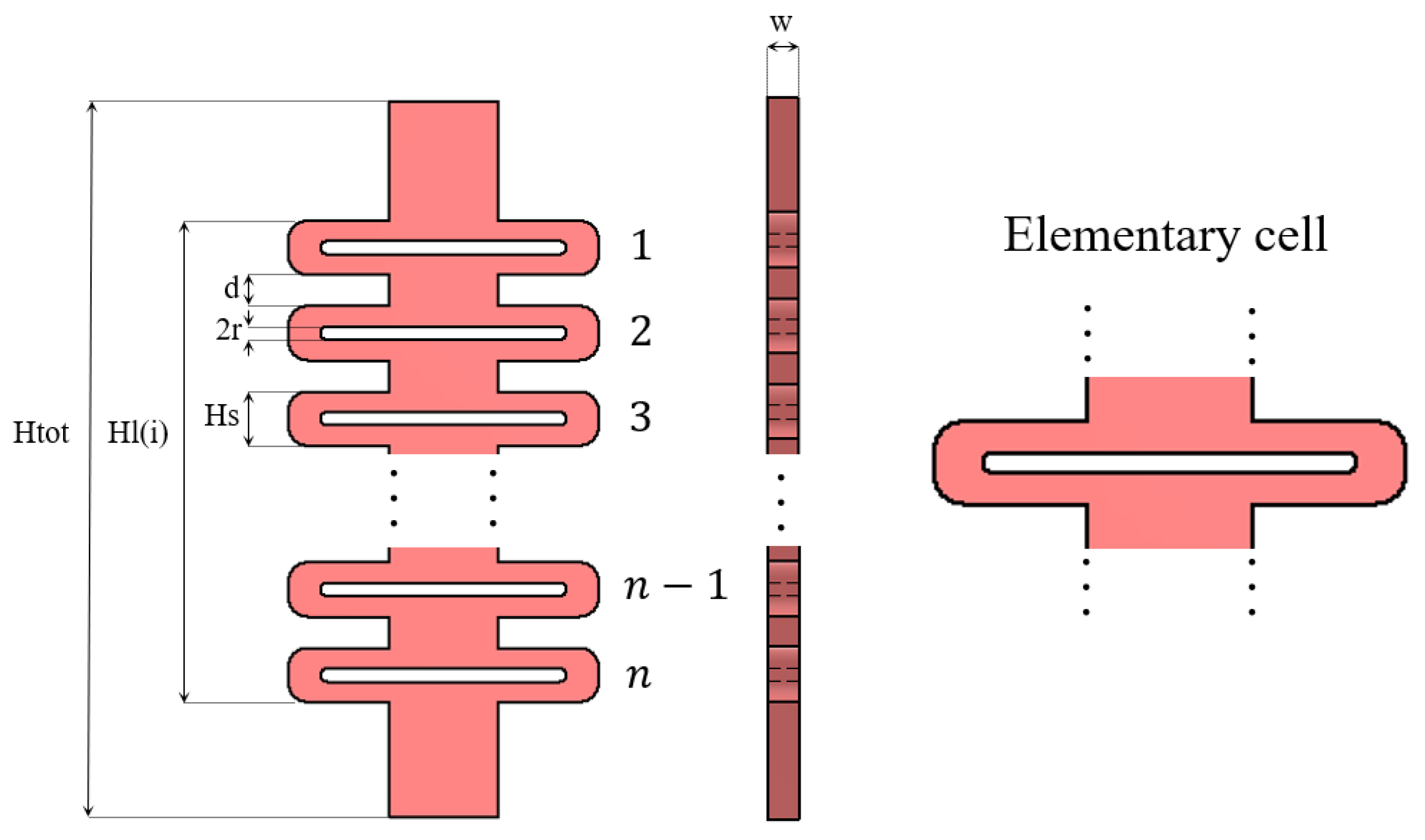
2.3. Design of Compliant Structures

Compliant structures must constrain the relative positions of the guiding rings in the resting state, while enabling finger flexion and promoting passive extension. Since the cable is routed in the palmar side, the compliant elements can be placed in the dorsal face. The compliant dorsal structures are designed based on a ribbon kirigami-inspired geometry [33]. A planar structure composed of elementary cells interconnected by segments arranged in a repeating configuration was developed to allow flexion and provide controlled mechanical compliance, making it suitable for applications requiring flexible yet structurally organized components. This solution can be effectively developed by exploiting the possibilities enabled by additive manufacturing technologies like Fused Deposition Modeling (FDM), that allows accurate control of the material deposition [34,35].
Figure 2 shows the structure of the compliant dorsal link proposed in this work. While in the kirigami structure a continuous ribbon of material is modified through strategic cut patterns and properly fold, we create strategic holes with AM to create interconnected elementary cells according to the pattern presented in the figure.
Among possible alternative designs, we choose this one based on previous evidence [34] that compared four different geometries and identified the proposed one as the best compromise between axial rigidity and bending. The structure shows a series of repeated cutouts that create elementary repetitive cells. Figure 2 highlights the main geometrical features that influence the mechanical behavior of the structure: H s is the length of an elementary cell, d is the space between adjacent cells, 2 r is the cut width, and w is the ribbon thickness.
A parametric CAD model was developed to allow customization of the presented target geometry. The length of the elementary cell was parametrized considering the optimal spacing derived from the optimization process, i.e., H l , the number of elementary cells q, and the distance d between cells, as shown in Equation (5).
H s = H l ( n 1 ) · d n
where H l is defined as
H l ( i ) = a i ( 1 k i o p t ) + a i + 1 k i + 1 o p t s i o p t
with i range from 1 to q 1 .
The cut width was set to 25% of H s to allow for flexion between the elementary cells and address the manufacturing constraints related to FDM. These constraints also prevent the design of structures that would be too thin to be reliably fabricated using FDM technology.

2.4. Exoskeleton Prototyping

Additive manufacturing allows customization of the mechanical design, keeping costs low. In this work, we decided to exploit FDM technology and multi-material printing [36] by using an Ultimaker Factor 4 printer (Ultimaker B.V., Utrecht, The Netherlands). Multi-material printing enables precise control over material deposition, allowing for the seamless integration of regions with varying stiffness, flexibility, and geometry within a single print. This is particularly advantageous in wearable applications like hand passive orthoses and exoskeletons, where comfort, fit, and mechanical performance are critical. The ability to create planar, skin-conforming geometries with targeted mechanical properties enhances user comfort while maintaining structural integrity and functionality. We used TPU95A (Ultimaker B.V., Utrecht, The Netherlands) for the soft domain and Nylon PA12 (Ultimaker B.V., Utrecht, The Netherlands) for the rigid domain due to their thermal compatibility and the optimal adhesion enabled at the interface (see Appendix A, [36]). By adjusting the infill density and infill patterns (see Appendix A), it is possible to obtain smooth surfaces which can be easily adapted to the hand morphology, promoting comfort when in direct contact with the skin. This makes the material potentially suitable also for long-term use. Moreover, the combination of TPU and Nylon PA12 ensures that the weight applied to the hand remains within acceptable limits for pediatric users, typically not exceeding 50 g, depending on the child’s age. Specifically, the proposed finger module features an extremely lightweight design, contributing to reduced inertia and improved comfort during use. For example, the module developed for the 12-year-old volunteer has a total weight of 37 g and the single finger module has a weight of 4 g. The guiding rings were divided into two rigid sections: one at the interlocking interface with the compliant dorsal links, and the other on the palmar side to provide anchor points. The remaining parts of the rings were made from TPU to enhance comfort and allow slight adaptability, accommodating possible finger size minor variations throughout the day (Figure 3).
To prevent the cables from running on bare skin and to properly route them to the fingers, a palm support (hereafter referred to as the frame) parametrized on the anatomical measures of the user was developed (Figure 4). The frame design includes guides to constraint cable direction, and pulleys to reduce friction.
The frame was modeled with a thickness of 0.8 mm to be easily foldable and secured over the dorsum of the hand and the forearm.

2.5. Characterization of Mechanical Components

To evaluate the mechanical properties of the exoskeleton components fabricated based on the proposed method, mechanical tests were performed using an Instron testing machine 3366 Tensile Tester (INSTRON®, High Wycombe, UK) equipped with a load cell (full scale: 500 N). The first test was conducted to evaluate the effect of different values of the geometrical parameters on the mechanical performance of the soft dorsal links, which are subject to elongation during finger flexion. Two different configurations, based on the number of elementary cells, were considered: three and six elements. Increasing the number beyond six would have resulted in structures that are too small to be practical for the typical phalanx length range observed in pediatric applications. In addition, three different thickness values were explored (0.8 mm, 1.6 mm, and 2.0 mm), corresponding to 4, 8, and 10 printed layers, respectively, depending on the adopted printing settings (see Appendix A). Overall, 6 different configurations were tested. For each configuration, a batch of 10 samples underwent tensile testing using an Instron machine set to a constant velocity of of 17 mm/s.
A prototype of the finger module developed by running the proposed optimization algorithm considering the measurements of a 12-year-old child was developed with the optimal geometrical configuration derived from the first test. The choice to test the finger module was driven by the need to prioritize the evaluation of the component requiring the highest level of customization in terms of geometry, structural robustness, and cable routing. Among the fingers that PHEX aims to support (thumb, index, and middle), the index and middle fingers present the longest phalanges, posing critical challenges for the transmission efficiency and mechanical alignment. Given that these two fingers share an identical mechanical architecture [37], the index finger module was selected as a representative case, under the assumption that the obtained performance results can be extended to the middle finger. This approach allowed us to optimize resources during the early design validation phase while laying the groundwork for subsequent integration into a complete multi-finger system. Additional work is planned to address the final integration, including system-level testing and user trials, as part of the broader development roadmap.
The phantom was mounted on a dedicated support presented in Figure 5a and connected to the lower grip fixture. The cable was attached to the load cell on the crosshead to perform actuation (Figure 5b).

3. Results

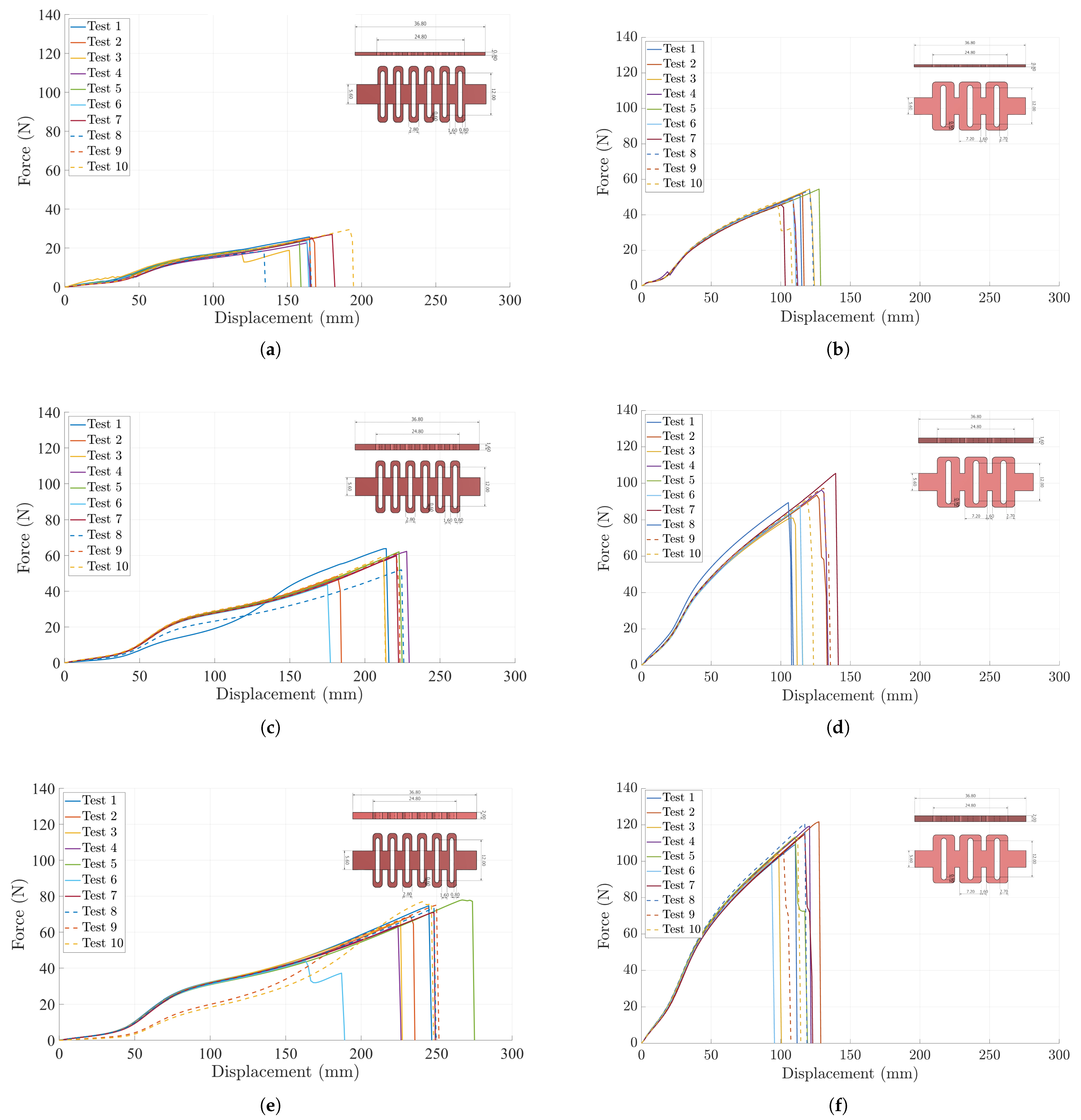
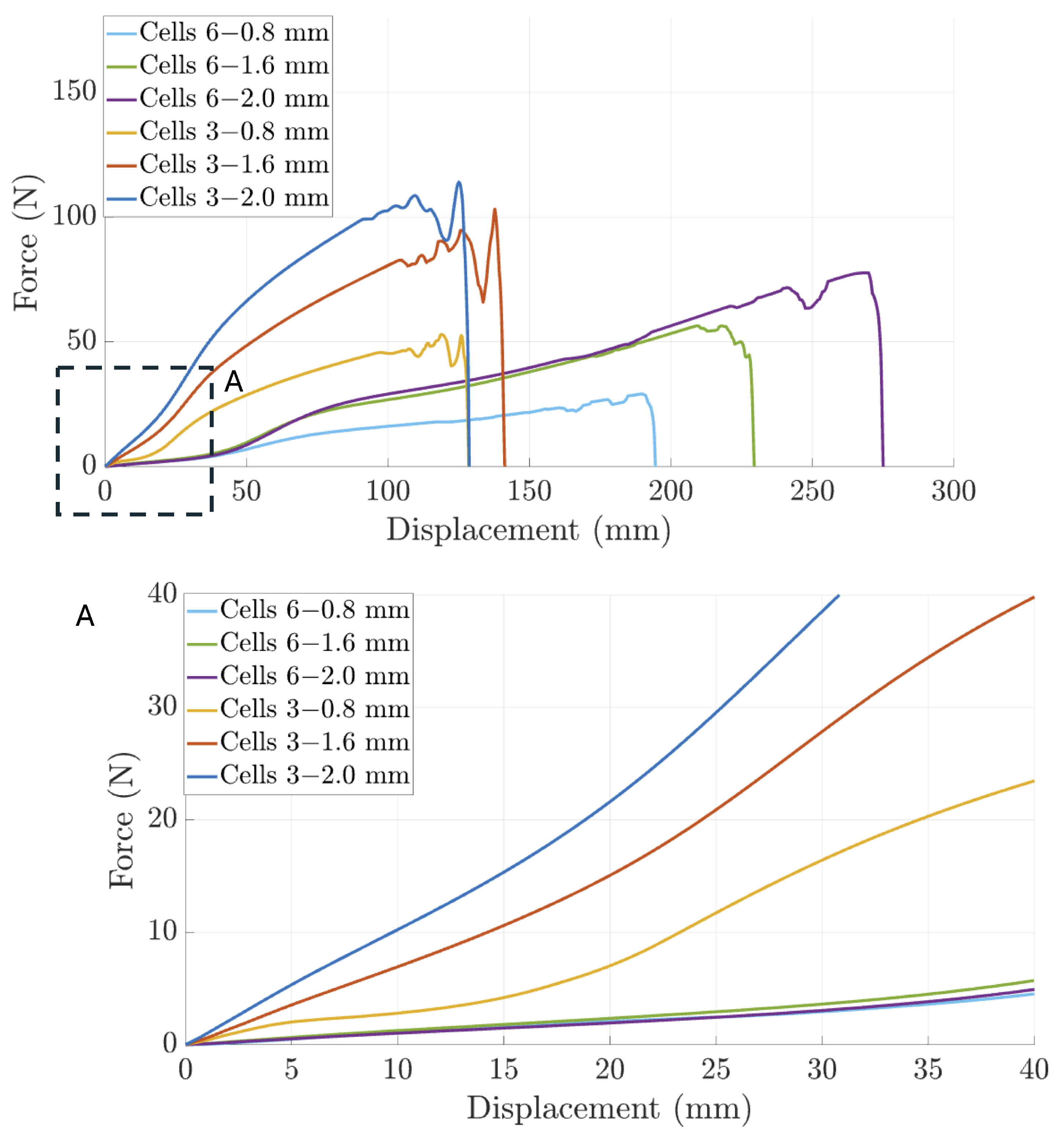
3.1. Characterization of Compliant Dorsal Links

The mechanical behavior of the geometrical configurations under test was averaged over the ten samples of each batch. Figure 6 shows the average behavior. The responce of each individual specimen is reported in Appendix B.
In the initial displacement range (0–25 mm, see Zoom A in Figure 6), the 3-cell samples with 2 mm thickness (blue, in Figure 6) and 1.6 mm thickness (orange, in Figure 6), in particular, resemble pseudo-linear elastic behavior. This behavior depends on both the thickness and number of elementary cells composing the kirigami-inspired structure. Beyond this range, up to 40 mm, the response transitions to a steady-state condition, where the deformation is primarily governed by material plasticity rather than cuts expansion. After 40 mm, plastic deformation occurs. The force required to reach 50 mm displacement varies among the configurations: for the 2-millimeter-thick samples, it ranges from approximately 40 N (6 cells) to 70 N (3 cells), whereas for the 0.8-millimeter-thick samples, it remains below 20 N for both cells configurations. The maximum recorded force significantly depends on both the thickness and the number of elementary cells. The 3-cell, 2-millimeter-thick sample (blue curve in Figure 6) peaks at approximately 120 N around 130 mm displacement, while the 1.6-millimeter-thick counterpart (orange, in Figure 6) exceeds 100 N before failure at roughly 140 mm (see Appendix B). The 0.8-millimeter-thick one (yellow, in Figure 6) reaches about 45 N before failure at nearly 130 mm. Thinner samples with more cells exhibit lower peak forces and greater displacements. The 6-cell, 0.8-millimeter-thick sample (light blue, in Figure 6) reaches around 35 N, failing at almost 200 mm. The 6-cell, 1.6-millimeter-thick sample (green, Figure 6) withstands up to 55 N, failing near 230 mm (see Appendix B for more details).

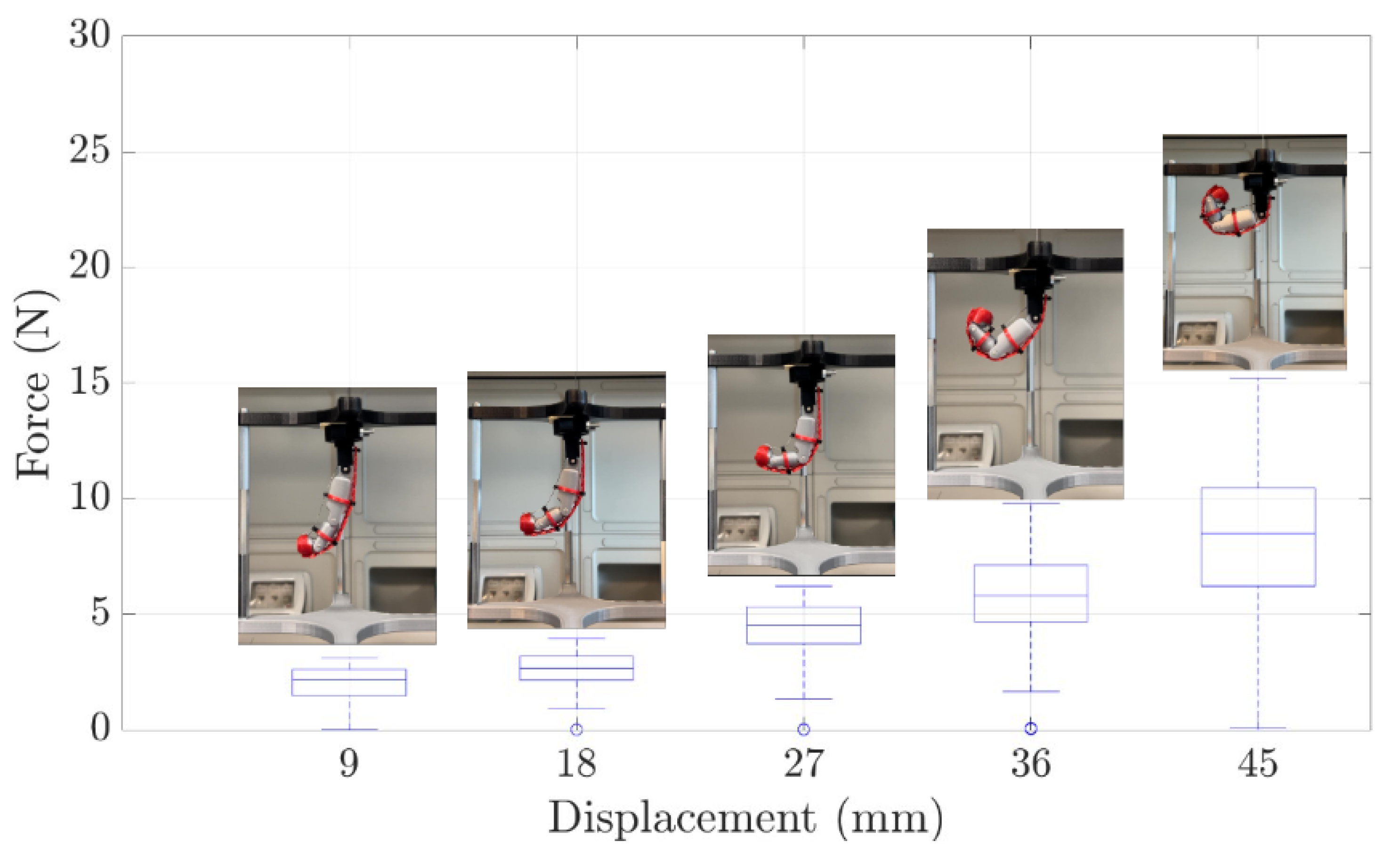
3.2. Experimental Evaluation of the Finger Module Prototype

Given that the project is currently in the preliminary design phase, the decision to perform a mechanical test on the compliant dorsal structure and on the assembled finger module was motivated by the need to evaluate the most appropriate manufacturing configuration for the compliant dorsal structure and bending behavior of the phantom on which the exoskeleton finger module will be worn. The primary objective of this test was to quantify the displacement and the force required to achieve full flexion when using the finger module prototype. The module was designed for a finger length of 77.5 mm (corresponding to the index finger of a 12-year-old children). According to this measure and considering the results of the mechanical characterization, a prototype of the index finger module was developed, including the following components: guidance rings with diameters of 17.5 mm for the proximal phalanx and 12 mm for the middle phalanx (both with a thickness of 3 mm) and compliant dorsal links consisting of 3 cells each, for both the proximal and distal pairs of anchor points.
The prototype was functionally tested to derive information on the cable stroke and force necessary to reach a complete finger flexion.
Figure 7 represents the relationship between the applied force and the cable displacement during finger flexion. The graph displays the mean force curve (dashed red line, Figure 7) along with the corresponding standard deviation (shaded blue area).
A progressive increase in force is observed as the cable displacement increases, indicating that the system requires a greater force to achieve full flexion. The trend is not perfectly linear but exhibits oscillations along the curve, which can be attributed to variations in contact points, friction phenomena in the utilized phantom, and, in particular, the progressive engagement of joints, as illustrated in Figure 7. The recruitment of each joint is indicated by a change in the concavity of the curve. Moreover, the compliant dorsal structures introduce additional resistance upon activation, influencing the recorded force profile. The total displacement required for complete flexion was determined to be 45 mm.
The standard deviation remains relatively low in the initial displacement, suggesting good repeatability in this phase. However, as displacement increases, data dispersion grows, indicating a slightly higher variability in the system response. This difference may be attributed to friction variations between trials, which affect the traction forces required during finger flexion.
A second test was carried out with the same experimental setting to test static behavior of the prototype. The cable stroke to reach a complete finger flexion was divided into five intervals (9 mm each) performing five trials for each phase. A total of 25 force-displacement points were obtained, from which a box-plot was generated to highlight the variability in the force required for system engagement at different level of cable stroke, as shown in Figure 8.
The box-plot shows a progressive increase in force as displacement increases, confirming that the system requires greater effort as flexion progresses. In the first two stages (9 mm and 18 mm displacement), the force exhibits limited variability, with relatively close medians and narrow whiskers. However, from 27 mm onward, data dispersion increases significantly, indicating greater variability in the system response. At 36 mm and 45 mm displacement, the largest force fluctuations are observed, with a wider distribution and the presence of outliers. In particular, in the final flexion phase (45 mm), the inter-quartile range expands, and extreme values deviate further from the median, suggesting that the system may encounter variable resistances due to friction phenomena or the progressive engagement of the compliant dorsal links.
For illustrative purposes and to assess wearability, Figure 9 presents a picture of the preliminary Phex prototype that was worn by a 12-year-old volunteer. The figure reveals the three distinct finger modules and the frame for the palm and dorsum of the hand. The use of Velcro©fasteners was selected to simplify the donning and doffing process, prioritizing ease of use and adjustability. To further enhance wearability, compliant dorsal links were anchored to the frame using flexible connections, facilitating quick attachment and removal of the exoskeleton.

4. Discussion and Conclusions

In the context of hand exoskeletons for pediatric patients, there remains a significant lack of available and suitable devices. This study addresses this gap by presenting the design and experimental evaluation of a novel finger module intended to support flexion during daily living activities. Rather than focusing on complete actuation and control systems, the study prioritizes the experimental deduction of the key quantitative requirements, such as stiffness, deformability, and cable stroke, necessary to inform future development and integration phases.
Tests performed using an Instron machine revealed that a cable stroke of approximately 45 mm is required to achieve full finger flexion. This information is critical for the sizing of actuators and the spatial configuration of the transmission block, providing a solid foundation for the design compact actuation systems. Additionally, analysis of force trends during phantom flexion highlighted variability influenced by friction and the progressive engagement of soft dorsal links. These findings suggest that future optimization should aim to reduce force fluctuations, particularly in the final stages of flexion, through friction minimization and improved material interface design.
The prototype was developed by using FDM AM, which allowed for rapid production and easy assembly of individually printed components. This modular design approach is especially well suited to pediatric applications, as it enables the replacement of specific components to accommodate patient growth, thereby enhancing the system sustainability and economic feasibility.
Tensile tests confirmed that increasing material thickness results in lower deformation, whereas a greater number of cells improves deformability. These insights are essential for fine-tuning the mechanical properties of the finger module, where compliance and rigidity must be carefully adjusted to ensure effective functional assistance.
The findings reported in this paper are aligned with broader research efforts in assistive robotics, particularly in response to the growing demand for personalized and sustainable healthcare solutions. As life expectancy increases globally, traditional care systems face rising pressure to support individuals with mobility impairments and chronic conditions. Wearable assistive devices such as pediatric exoskeletons offer promising solutions by extending autonomy, enhancing rehabilitation outcomes, and improving quality of life.
Although actuation, control, and sensing aspects were beyond the scope of this work, the design and testing of the finger module provided foundational data that will support their integration in future stages. The results presented here can inform the development of more adaptive, intelligent assistive systems (potentially enhanced by smart sensing and AI-driven control) to meet the dynamic needs of users. This aligns with the objectives of next-generation assistive robotics: to deliver impactful, scalable, and user-centered technologies that respond effectively to the challenges of aging populations and pediatric care.
Future work will focus on integrating electronics, refining the actuation and transmission systems for greater compactness, and investigating the material and human-exoskeleton interfaces to enhance system performance, reliability, and long-term adaptability. In a future long-term study, the use of the device will be extended to a larger group of users. Standardized evaluation scales will be administered to quantitatively assess user satisfaction. Particular attention will be devoted to aspects related to comfort and breathability of the device, given their relevance for prolonged use, manipulating the frame texture from the slicer software. It is also necessary to enhance the safety of the device. For this reason, it is planned to incorporate a dual protection system—mechanical and electrical. From a mechanical point of view, the implementation of a locking mechanism to prevent the cable from being pulled beyond the functional limit of its stroke is recognized as a necessary safety measure. In parallel, the integration of electrical safeguards, such as overcurrent protection, is essential to ensure the integrity of the device’s circuitry and prevent potential malfunctions.

Author Contributions

Conceptualization: E.D., A.C. and F.T.; Methodology: E.D., G.L., L.N. and A.C.; Software: G.L.; Validation: E.D. and G.L.; Formal analysis: G.L.; Investigation: E.D.; Resources: L.Z.; Data curation: E.D. and G.L.; Writing—original draft preparation: E.D. and G.L.; Writing—review and editing: A.C., L.N. and F.T.; Supervision: F.T., L.Z. and N.L.T.; Project administration: F.T. All authors have read and agreed to the published version of the manuscript.

Funding

This work was funded by the Istituto Nazionale per l’Assicurazione contro gli Infortuni sul Lavoro (INAIL) within the 3D-AID and 3Daid++ projects (respective CUPs, E59E19001460005 and C83C23001060001) and by Università Campus Bio-Medico within the Proof of Concept project HANDy, Human hANd custom prosthetic Devices (GR7039-GEN0477).

Institutional Review Board Statement

The study was conducted in accordance with the Declaration of Helsinki, and approved by the Italian National Ethics Committee for Pediatric Clinical Trials, authorization no. 0008057 dated 21 January 2025.

Informed Consent Statement

Informed consent was obtained from parents of the child enrolled.

Data Availability Statement

The raw data supporting the conclusions of this article will be made available by the authors on request.

Acknowledgments

The authors would like to thank Lucia Tontini for her valuable assistance with the printing processes.

Conflicts of Interest

The authors declare no conflicts of interest.

Abbreviations

The following abbreviations are used in this manuscript:
ADLActivities of daily living
ASDAutism disorder spectrum
BPIBrachial plexus injury.
CMCCarpometacarpal joint
CPCerebral palsy
DIPDistal interphalangeal joint
DMDDuchenne muscular distrophy
DOFDegree of freedom
IPInterphalangeal joint
MASModified Ashworth Scale
MCPMetacarpophalangeal joint
PIPProximal interphalangeal joint
TBITraumatic brain injury
TRLTechnology Readiness Levels

Appendix A. Set Up Parameters of Ultimaker Factor 4

This appendix details the parameters utilized in the slicer for the purpose of 3D-printing. The table presents a summary of the parameters of particular interest, with the materials used in multifilament printing highlighted.
Table A1. Set up parameters for 3D-printing.
MaterialInfill Density [%]Infill PatternPrinting Temperature [°]Build Plate Temperature [°]Print Speed [mm/s]Fan Speed [%]Wall thikness [mm]
TPU50Zig Zag2254035500.8
Nylon20Triangles2504080751.2

Appendix B. Complete Behavior of Compliant Dorsal Links

In this appendix, the stress–strain curves obtained from tensile tests conducted on TPU 95A samples using an Instron machine at a strain rate of 17 mm/s are presented. These curves illustrate the influence of the geometric parameters and thickness on the mechanical behavior of the material under tensile loading. Reducing the number of cells alters the stress distribution, generally resulting in a more compliant mechanical response compared to the 6-cells configuration. The failure phase is more evident in thinner samples, with a sharper transition from the elastic to the plastic region.
Figure A1. (ac) Geometry with 6 cells: these graphs compare the effect of thickness (0.8 mm, 1.6 mm, 2 mm) on the mechanical properties of TPU 95A. Increasing thickness leads to higher mechanical strength, with greater stress resistance before plastic deformation. The initial slope indicates that thicker samples exhibit a stiffer elastic response, whereas the thinnest sample (0.8 mm) undergoes more pronounced deformation under the same stress level. (df) Geometry with 3 cells: these graphs illustrate the dependence of mechanical properties on thickness, showing a similar trend as the 6-ribbon geometry.
Applsci 15 05694 g0a1

References

  1. Focaroli, V.; Taffoni, F.; Velardi, A.; Caravale, B.; Keller, F. Object Exploration and Manipulation in Infants at Typical vs. Elevated Likelihood for ASD: A Review. Children 2024, 11, 825. [Google Scholar] [CrossRef] [PubMed]
  2. Hall, M.L.; Lobo, M.A. Design and development of the first exoskeletal garment to enhance arm mobility for children with movement impairments. Assist. Technol. 2018, 30, 251–258. [Google Scholar] [CrossRef] [PubMed]
  3. Gonzalez, A.; Garcia, L.; Kilby, J.; McNair, P. Robotic devices for paediatric rehabilitation: A review of design features. Biomed. Eng. Online 2021, 20, 1–33. [Google Scholar] [CrossRef]
  4. Randazzo, L.; Iturrate, I.; Perdikis, S.; Millán, J.D.R. mano: A wearable hand exoskeleton for activities of daily living and neurorehabilitation. IEEE Robot. Autom. Lett. 2017, 3, 500–507. [Google Scholar] [CrossRef]
  5. Bützer, T.; Dittli, J.; Lieber, J.; van Hedel, H.J.; Meyer-Heim, A.; Lambercy, O.; Gassert, R. PEXO-A pediatric whole hand exoskeleton for grasping assistance in task-oriented training. In Proceedings of the 2019 IEEE 16th International Conference on Rehabilitation Robotics (ICORR), Toronto, ON, Canada, 24–28 June 2019; Volume 16, pp. 108–114. [Google Scholar] [CrossRef]
  6. Søraa, R.; Fosch-Villaronga, E. Exoskeletons for all: The interplay between exoskeletons, inclusion, gender, and intersectionality. Paladyn J. Behav. Robot. 2020, 11, 217–227. [Google Scholar] [CrossRef]
  7. Fosch-Villaronga, E.; Čartolovni, A.; Pierce, R.L. Promoting inclusiveness in exoskeleton robotics: Addressing challenges for pediatric access. Paladyn J. Behav. Robot. 2020, 11, 327–339. [Google Scholar] [CrossRef]
  8. Du Plessis, T.; Djouani, K.; Oosthuizen, C. A review of active hand exoskeletons for rehabilitation and assistance. Robotics 2021, 10, 40. [Google Scholar] [CrossRef]
  9. Bunch, P.M.; Altes, T.A.; McIlhenny, J.; Patrie, J.; Gaskin, C.M. Skeletal development of the hand and wrist: Digital bone age companion—A suitable alternative to the Greulich and Pyle atlas for bone age assessment? In Skeletal Radiology; Springer: New York, NY, USA, 2017; Volume 46, pp. 785–793. [Google Scholar] [CrossRef]
  10. Snyder, R.; Schneider, L.; Owings, C.; Reynolds, H. Anthropometry of Infoants, Children, and Youths to Age 18 for Product Safety Design. 1977. Available online: https://trid.trb.org/View/57257 (accessed on 19 June 2024).
  11. Aubin, P.; Petersen, K.; Sallum, H.; Walsh, C.; Correia, A.; Stirling, L. A pediatric robotic thumb exoskeleton for at-home rehabilitation: The Isolated Orthosis for Thumb Actuation (IOTA). Int. J. Intell. Comput. Cybern. 2014, 7, 233–252. [Google Scholar] [CrossRef]
  12. Haarman, C.J.W. Development of a Functional Hand Orthosis for Boys with Duchenne Muscular Dystrophy. Master’s Thesis, University of Twente, Enschede, The Netherlands, 30 September 2016. Available online: https://ris.utwente.nl/ws/portalfiles/portal/60773794/CONFIDENTIAL_PDEng_Thesis_Claudia_Haarman.pdf (accessed on 13 September 2024).
  13. Refour, E.; Sebastian, B.; Ben-Tzvi, P. Design and implementation of an exoskeleton glove for infant medical rehabilitation. Int. Des. Eng. Tech. Conf. Comput. Inf. Eng. Conf. 2018, 51807, V05AT07A062. [Google Scholar] [CrossRef]
  14. Siyi. 2017. Syrebo. Available online: https://it.syrebo.com/rehabilitationequipment-for-home/soft-robotic-glove-children.html (accessed on 20 July 2024).
  15. Syrebo Care. Newest Model: Syrebo C12 Stroke Hand Rehabilitation Gloves with 6 Training Modes, 9 Strength Levels. 2023. Available online: https://www.youtube.com/watch?v=Scd-Nf-W3tM (accessed on 23 July 2024).
  16. Bianchi, M.; Secciani, N.; Ridolfi, A.; Vannetti, F.; Pasquini, G. Kinematics-based strategy for the design of a pediatric hand exoskeleton prototype. In Advances in Italian Mechanism Science: Proceedings of the Second International Conference of IFToMM Italy, Cassino, Italy, 29–30 November 2018; Springer: Berlin/Heidelberg, Germany, 2019; pp. 501–508. [Google Scholar] [CrossRef]
  17. Dittli, J.; Goikoetxea-Sotelo, G.; Lieber, J.; Gassert, R.; Meyer-Heim, A.; Van Hedel, H.J.; Lambercy, O. A Tailorable Robotic Hand Orthosis to Support Children with Neurological Hand Impairments: A Case Study in a Child’s Home. In Proceedings of the 2023 International Conference on Rehabilitation Robotics (ICORR), Singapore, 24–28 September 2023; pp. 1–6. [Google Scholar] [CrossRef]
  18. Lieber, J.; Dittli, J.; Lambercy, O.; Gassert, R.; Meyer-Heim, A.; van Hedel, H.J. Clinical utility of a pediatric hand exoskeleton: Identifying users, practicability, and acceptance, and recommendations for design improvement. J. Neuroeng. Rehabil. 2022, 19, 17. [Google Scholar] [CrossRef]
  19. Dittli, J.; Vasileiou, C.; Asanovski, H.; Lieber, J.; Lin, J.B.; Meyer-Heim, A.; Lambercy, O. Design of a compliant, stabilizing wrist mechanism for a pediatric hand exoskeleton. In Proceedings of the 2022 International Conference on Rehabilitation Robotics (ICORR), Rotterdam, The Netherlands, 25–29 July 2022; pp. 1–6. [Google Scholar] [CrossRef]
  20. Srivastava, R.; Singh, M.; Gomes, G.D.; Murray, N.; Devine, D. SM-EXO: Shape Memory alloy-based Hand EXOskeleton for Cobotic Application. In Proceedings of the 2022 31st IEEE International Conference on Robot and Human Interactive Communication (RO-MAN), Napoli, Italy, 29 August–2 September 2022; pp. 1277–1284. [Google Scholar] [CrossRef]
  21. Tran, P.; Jeong, S.; Lyu, F.; Herrin, K.; Bhatia, S.; Elliott, D. FLEXotendon glove-III: Voice-controlled soft robotic hand exoskeleton with novel fabrication method and admittance grasping control. IEEE/ASME Trans. Mechatron. 2022, 27, 3920–3931. [Google Scholar] [CrossRef]
  22. Tran, P.; Elliott, D.; Herrin, K.; Desai, J.P. Towards comprehensive evaluation of the FLEXotendon glove-III: A case series evaluation in pediatric clinical cases and able-bodied adults. Biomed. Eng. Lett. 2023, 13, 485–494. [Google Scholar] [CrossRef] [PubMed]
  23. Noronha, B.; Accoto, D. Exoskeletal devices for hand assistance and rehabilitation: A comprehensive analysis of state-of-the-art technologies. IEEE Trans. Med. Robot. Bionics 2021, 3, 525–538. [Google Scholar] [CrossRef]
  24. Khatik, V.; Saxena, A. On Optimal Tendon Routing Based Design of Biologically Inspired Underactuated Hand Exoskeleton for Gross Grasping. IEEE Trans. Med. Robot. Bionics 2024, 6, 600–617. [Google Scholar] [CrossRef]
  25. Lin, L.; Zhang, F.; Yang, L.; Fu, Y. Design and modeling of a hybrid soft-rigid hand exoskeleton for poststroke rehabilitation. Int. J. Mech. Sci. 2021, 212, 106831. [Google Scholar] [CrossRef]
  26. Salazar, G.; Russi-Vigoya, M.N. Technology readiness level as the foundation of human readiness level. Ergon. Des. 2021, 29, 25–29. [Google Scholar] [CrossRef]
  27. Kuo, F.-L.; Lee, H.-C.; Hsiao, H.-Y.; Lin, J.-C. Robotic-assisted hand therapy for improvement of hand function in children with cerebral palsy: A case series study. Eur. J. Phys. Rehabil. Med. 2020, 56, 237–242. [Google Scholar] [CrossRef]
  28. Bressi, F.; Santacaterina, F.; Cricenti, L.; Campagnola, B.; Nasto, F.; Assenza, C.; Morelli, D.; Cordella, F.; Lapresa, M.; Zollo, L.; et al. Robotic-assisted hand therapy with Gloreha Sinfonia for the improvement of hand function after pediatric stroke: A case report. Appl. Sci. 2022, 12, 4206. [Google Scholar] [CrossRef]
  29. Battraw, M.A.; Young, P.R.; Welner, M.E.; Joiner, W.M.; Schofield, J.S. Characterizing Pediatric Hand Grasps During Activities of Daily Living to Inform Robotic Rehabilitation and Assistive Technologies. In Proceedings of the 2022 International Conference on Rehabilitation Robotics (ICORR), Rotterdam, The Netherlands, 25–29 July 2022; pp. 1–6. [Google Scholar] [CrossRef]
  30. Buchholz, B.; Armstrong, T.J.; Goldstein, S.A. Anthropometric data for describing the kinematics of the human hand. Ergonomics 1992, 35, 261–273. [Google Scholar] [CrossRef]
  31. Gerez, L.; Chen, J.; Liarokapis, M. On the development of adaptive, tendon-driven, wearable exo-gloves for grasping capabilities enhancement. IEEE Robot. Autom. Lett. 2019, 4, 422–429. [Google Scholar] [CrossRef]
  32. Lapresa, M.; Ceccarelli, A.; Taffoni, F.; Tagliamonte, N.L.; Zollo, L.; Cordella, F. Analysis of hand intra-finger couplings during flexion movements in the free space. IEEE Access 2023, 11, 90084–90093. [Google Scholar] [CrossRef]
  33. Sun, Y.; Ye, W.; Chen, Y.; Fan, W.; Feng, J.; Sareh, P. Geometric design classification of kirigami-inspired metastructures and metamaterials. Structures 2021, 33, 3633–3643. [Google Scholar] [CrossRef]
  34. Lei, Q.E.; Shu, J.; Wang, J.; Cheung, H.Y.; Cheung, J.P.; Wong, W.F.; Tong, R.K. Design and characterize of kirigami-inspired springs and the application in vertebrae exoskeleton for adolescent idiopathic scoliosis brace treatment. Front. Mech. Eng. 2023, 9, 1152930. [Google Scholar] [CrossRef]
  35. Cuellar, J.S.; Smit, G.; Zadpoor, A.A.; Breedveld, P. Ten guidelines for the design of non-assembly mechanisms: The case of 3D-printed prosthetic hands. Proc. Inst. Mech. Eng. Part H 2018, 232, 962–971. [Google Scholar] [CrossRef]
  36. Nini, L.; Tontini, L.; Tagliamonte, N.; Zollo, L.; Taffoni, F. Design of compliant components in linkage-driven prosthetic fingers: A Multi-Material printing based method. IEEE Access 2024, 12, 190959–190971. [Google Scholar] [CrossRef]
  37. Bullock, I.M.; Borràs, J.; Dollar, A.M. Assessing assumptions in kinematic hand models: A review. In Proceedings of the 2012 4th IEEE RAS & EMBS International Conference on Biomedical Robotics and Biomechatronics (BioRob), Rome, Italy, 24–27 June 2012; pp. 139–146. [Google Scholar] [CrossRef]
Figure 1. (a) Fingers geometric model in a flexed configuration, with representative zoomed-in view of the force decomposition; Joints are represented with different markers: a square for the MCP joint, a star for the PIP joint, and a triangle for the DIP joint; (b) Anthropometric measurements highlighted: hand breadth (HB), hand length (HL), palm height ( h p ), D i diameter at i-th phalanx; (c) finger in a rest configuration, with representative zoomed-in view of the distance between two consecutive anchor points.
Applsci 15 05694 g001
Figure 2. Compliant dorsal structure inspired by ribbon kirigami and definition of the main geometrical features considered.
Applsci 15 05694 g002
Figure 3. (a) CAD designs with a lateral view showing the thicknesses w, that was selected to be: 0.8 mm, 1.6 mm, and 2 mm, for the geometric model. From left compliant dorsal link with three cells. The two extremities are functional for anchoring to the guiding rings. (b) Design and dimensions (in mm) of the ring. In the image, the hole for cable routing can be seen in the top right, and the housing for the compliant dorsal link is visible in the bottom left.
Applsci 15 05694 g003
Figure 4. Design of the wearable frame. The measurements presented are: hand breadth (HB), height palm (HP), and diameter foream (Df). View A: detail of guide: View B: pulley to prevent the cable from making a 90-degree angle and to reduce friction.
Applsci 15 05694 g004
Figure 5. (a) illustrates the general set up with phantom worn Phex; (b) illustrates 3D-printed support for the Instron machine; (c) illustrates the phantom with Phex worn.
Applsci 15 05694 g005
Figure 6. Mean curve representation of the analyzed data. The average behavior of the specimen highlights trends across different configurations. In the initial phase of the test (zoom A), characterized by low load and low displacement, a geometry-induced, repeatable response is observed—resembling a pseudo-elastic behavior. This effect arises from the kirigami-inspired structure rather than from the intrinsic material properties, and reflects the reversible deformation enabled by the cellular layout under controlled conditions.
Applsci 15 05694 g006
Figure 7. Mean force curve graph of the complete flexion of the exoskeleton, highlighting the standard deviation. The graph displays the average force from the conducted experiments as a dashed red line, with the light blue shaded area representing the standard deviation across tests.
Applsci 15 05694 g007
Figure 8. Box-plot of the force required for bending the phantom at 5 different displacement steps of 9 mm, from 0 mm up to complete flexion of 45 mm.
Applsci 15 05694 g008
Figure 9. The first image depicts the front view of the subject with Phex worn. The second image presents the subject from the side, also with Phex worn. The third image shows the back view of the subject with Phex worn. The fourth image presents all components of Phex.
Applsci 15 05694 g009
Table 1. Overview of pediatric hand exoskeletons.
ReferenceFuncDiseaseStage of DevelopmentAge [y]ActuationTypeTested GraspsWeight [g]DoASensorsMotion IntentionAssisted District
Motor Transm. Hand Total Fingers Joint
IOTA (2014) [11]R 1CP 3Prototype7–12ServoInd. DOFRigidOpposition2302Encoders, bendExplicit1 C M C 1 , M C P 1
Haarman et al. (2016) [12]A 2DMD 4Prototype20–23DCConstr. slideSoft-rigidPinch, power<7522522–3 M C P 2 , 3 , P I P 2 , 3 , D I P 2 , 3
Refour et al. (2018) [13]RCPClinical trial1–3DCCoupl. DOFRigidPinch2Encoders, FSRExplicit1–2 M C P 2 , P I P 2 , D I P 2 , IP
SYREBO (2018) [14,15]RStrokeCommercial5–12Pneum.BladderSoftPinch, power, opposition<150<20005Explicit1–5 M P C 1 5 , P I P 1 4 , D I P 1 4 , IP
Bianchi et al. (2019) [16]ACPPrototypeServoCoupl. DOFRigid12–5 M C P 1 5 , P I P 1 4 , D I P 1 4
PEXO (2019) [5,17,18,19]ACPClinical trial6–12DCConstr. slideSoft-rigidPinch, power, opposition84–1014923TTL triggerImplicit/Explicit1–5CMC, M C P 1 5 , D I P 1 4
SM-EXO (2022) [20]RASD 5PrototypeCable on gloveSoft50KPTsImplicit1–3 M C P 1 3 , P I P 2 , 3 , D I P 2 , 3 , IP
FLEXotendon Glove-III (2023) [21,22]ATBI 6, BPI 7Clinical trial12DCCable on gloveSoftPinch, power, opposition13151005Tension sensorsExplicit1–3 M C P 1 3 , P I P 2 , 3 , D I P 2 , 3 , IP
1 Rehabilitation; 2 Assistive; 3 Cerebral palsy; 4 Duchenne muscular disorder; 5 Autism spectrum disorder; 6 Traumatic brachial injury; 7 Brachial plexus injury. CMC: Carpometacarpal joint; MCP: Metacarpophalangeal joint; PIP: Proximal Interphalangeal joint; DIP: Distal Interphalangeal joint; IP: Interphalangeal joint. Fingers are numbered 1 (thumb) to 5 (little finger).
Disclaimer/Publisher’s Note: The statements, opinions and data contained in all publications are solely those of the individual author(s) and contributor(s) and not of MDPI and/or the editor(s). MDPI and/or the editor(s) disclaim responsibility for any injury to people or property resulting from any ideas, methods, instructions or products referred to in the content.

