Article

Research on Fractional-Order Control of Anchor Drilling Machine Optimized by Intelligent Algorithms

1
Key Laboratory of In-Situ Property-Improving for Mining of Ministry of Education, Taiyuan University of Technology, Taiyuan 030024, China
2
College of Mining Engineering, Taiyuan University of Technology, Taiyuan 030024, China
3
Engineering Research Center of Advanced Metal Composites Forming Technology and Equipment, Ministry of Education, Taiyuan University of Technology, Taiyuan 030024, China
4
College of Mechanical Engineering, Taiyuan University of Technology, Taiyuan 030024, China
5
School of Mathematics and Statistics, Taiyuan Normal University, Jinzhong 030619, China
*
Author to whom correspondence should be addressed.
Appl. Sci. 2025, 15(10), 5656; https://doi.org/10.3390/app15105656
Submission received: 17 April 2025 / Revised: 14 May 2025 / Accepted: 15 May 2025 / Published: 19 May 2025

Abstract

:
Anchor–bolt support operations are lengthy and conducted under harsh conditions, restricting the efficiency and safety of roadway excavation. To address these challenges, we developed an integrated solution combining mechanical structure optimization with control algorithms. Specifically, we designed a novel automated drilling system equipped with a robotic manipulator and an anchor–bolt magazine to handle modular hollow self-drilling anchor bolts, enabling automated support operations. To achieve precise docking in unmanned conditions, we employed an inner-loop fractional-order proportional–integral–derivative (FOPID) controller optimized by an improved particle swarm optimization (ILPSO) algorithm. Additionally, robust control based on H∞ control theory was introduced to ensure reliable system performance under disturbances and model uncertainties. Simulation results indicate that the ILPSO-tuned FOPID controller significantly outperforms conventional controllers in dynamic response accuracy; frequency–domain analysis further confirms that the H∞ control approach enhances system stability. Collectively, these results provide a theoretical basis for advancing automated mining technologies.

1. Introduction

Rock mass control in coal mine roadways is pivotal for underground safety. Nevertheless, automation in roadway excavation and support still lags behind, leading to a pronounced imbalance between mining and bolting operations [1]. Conventional bolt support workflows are multi-step, time-consuming and labor-intensive, which heightens the risk of accidents [2,3]. Although purpose-built equipment—such as bolter miners and drill-bolter integrated rigs—has been introduced, the installation of drill rods and anchoring agents continues to rely on manual intervention [4,5]. In line with the move toward unmanned operations, the hydraulic control system of an anchor drilling rig must deliver high positioning accuracy, fast dynamic response and strong robustness under harsh, variable conditions; traditional PID controllers struggle to satisfy all of these requirements simultaneously.
To address this, researchers have conducted extensive research on the automation of anchor drilling rigs and their control performance. The Swedish Sandvik modular drilling rig is equipped with a BH bolting head and an RD rock drill, enabling automated installation of 1.5–3.0 m rock bolts [6]. The Komatsu ZB21 bolter, produced in Japan, integrates a Jennmar pumpable resin system that injects anchoring resin into the drilled hole after boring, thereby improving ground support efficiency [7]. The J.H. Fletcher drill rig from the United States features built-in dust removal ports coupled with a fan synchronization system, effectively reducing concentrations of dust generated during drilling. The integrated drilling–grouting–bolting rig developed by China Coal Technology’s Taiyuan Institute incorporates a grout mixer within the anchor bolt, enabling mechanized support and improving efficiency in inclined roadways [8]. Reference [9] proposed a bolt-grouting reinforcement method for deep fractured rock masses, combining prestressed anchors with self-stress grouting to address grout–rock interface relaxation caused by cement-based material shrinkage. Although these advancements have significantly enhanced the automation level of bolting operations, most systems still require manual assistance for critical tasks such as anchoring agent installation. This residual dependence on human intervention limits their suitability for fully unmanned deployment.
Furthermore, achieving high-precision hydraulic control is an essential prerequisite for autonomous bolting, particularly in response to complex underground conditions and dynamic disturbances. Existing studies on anchor drilling rig control have explored various approaches. Reference [10] developed a straddle-type automatic anchoring rig, enabling synchronous parallel excavation–support operations and mitigating coupling vibrations between surrounding rock and the anchoring system to enhance drilling stability. Reference [11] developed an adaptive control approach with genetic algorithm-optimized PID parameters to dynamically adjust rotation speed and propulsive force, thereby mitigating drill pipe damage and enhancing coal cutting efficiency. Reference [12] studies spool displacement characteristics within a load port independent control system and designs a two-level fuzzy PID controller along with its related algorithms, thereby achieving favorable outcomes in pressure–flow composite control. However, existing control research for anchor drilling rigs struggles to simultaneously achieve both high precision and strong robustness under complex working conditions.
In contrast, fractional-order control (FOC) theory, proposed by Igor Podlubny [13], has demonstrated potential advantages in dynamic response and robustness, and has progressively achieved favorable application results in various fields such as precision machining control, wind turbines, electrohydraulic systems, twin rotor systems, rail vehicle tilt control, and industrial electrical drives [14,15,16,17]. But regarding fractional-order PID (FOPID) controllers, existing studies have predominantly focused on validating their control effectiveness through dynamic performance indicators such as step response, while theoretical analysis and systematic validation of their stability and robustness against external disturbances remain insufficient.
To overcome the bottlenecks of existing support equipment in terms of automation and robustness, this paper proposes a mechanical structure for an anchor drilling rig and a fractional-order control strategy synergistically optimized by intelligent algorithms and robust control. First, the automatic grabbing and loading of anchor bolts is achieved by integrating the anchor bolt magazine and a robotic manipulator; simultaneously, the level of automation is enhanced by adopting extended hollow anchor bolts combined with grouting support. Specifically targeting the robustness challenges in complex coal mine environments, the FOPID controller is optimized using the improved particle swarm optimization (ILPSO) algorithm to enhance dynamic performance. To further analyze and enhance the system’s disturbance rejection capability under harsh working conditions, this paper integrates H∞ robust control to formulate a composite control strategy, and employs frequency domain analysis techniques to conduct a detailed analysis and validation of the system’s stability and robustness. Simulations and frequency domain analysis demonstrate the advantages of the proposed control strategy in improving the precision and robustness of the support equipment, providing a theoretical and technical basis for enhancing the operational reliability of the support equipment in harsh environments.

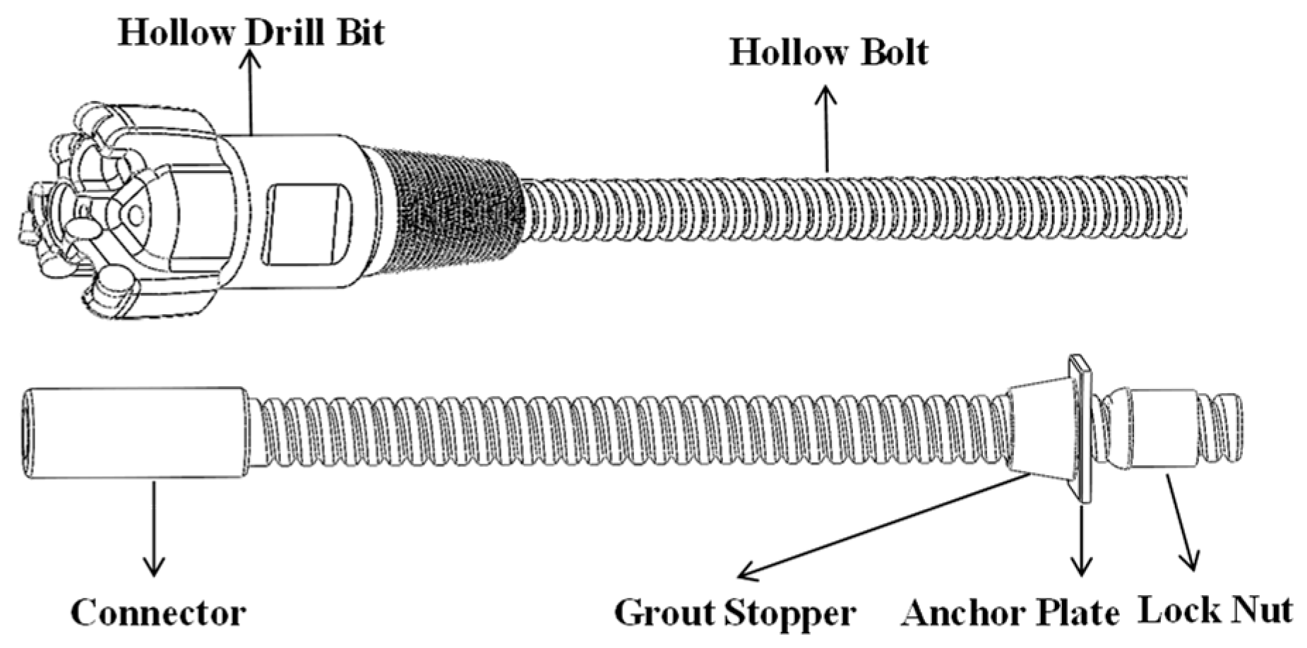
2. Drilling and Bolting Robot Rig Structure and Workflow

Currently, the common support process for anchor drilling rigs in China includes steps such as drilling, unloading drill rods, installing anchoring agents, installing anchor bolts, mixing anchoring agents, and pre-tensioning. To improve operational automation, this paper designs a new type of anchor drilling rig that integrates an anchor bolt magazine with automated support operations. It utilizes extended hollow self-drilling anchor bolts combined with liquid anchoring agents to achieve rapid support and simplify the construction process. As shown in Figure 1, the rig consists of a robotic arm, anchor bolt magazine, power head, anchor bolt clamping mechanism, and support structure (including top plate, bottom plate, and side plates). The anchor bolt magazine is located between the top and bottom plates and is divided into two layers, with five storage positions per layer. The interlayer movement of anchor bolts is achieved via a sprocket and chain mechanism, and the bolts are fixed by spring-loaded cassettes. The robotic arm moves along guiding columns and can extend vertically to perform grabbing actions, moving the anchor bolt to the power head for installation. The drilling mechanism is driven vertically by a chain and hydraulic cylinder, while the power head uses an externally meshed gear motor with hollow grouting capabilities. The top is equipped with an anchor bolt clamping mechanism for fixing the anchor bolt.
As shown in Figure 2, the extended hollow self-drilling anchor consists of a hollow shaft with a drill bit at the upper end and a hollow anchor bolt at the lower end, equipped with a connector and fastening bolts. This design, in conjunction with the drilling rig, enables integrated drilling and grouting operations. The support process is as follows: after aligning the drilling rig with the target support area of the roadway, the robotic arm retrieves the upper self-drilling anchor and installs it onto the power head. Once the anchor reaches the predetermined depth, the clamping mechanism secures the anchor, allowing the power head to disengage. The robotic arm then grabs the lower anchor, connects it, and continues drilling. Finally, the anchoring agent is injected through the hollow anchor bolt; after it solidifies, the anchor is clamped, and the nut is tightened to complete the support.
Coupled with the proposed drilling–grouting equipment, a staged bolting strategy is implemented for high in situ stress, soft-rock conditions. The initial rapid-closure phase employs short self-drilling anchors to arrest early convergence, after which additional hollow anchor sections are joined at predetermined depths and times—selected on the basis of real-time deformation monitoring—to form a long, continuous bolt. This phased sequence limits bolt–rock relative displacement during installation, reduces axial stress concentration, and prevents the premature tensile failure occasionally encountered in one-step long bolt placement, thereby enhancing the durability and reliability of the overall support system.
Although the intelligent drilling rig improves operational efficiency through its structural design and workflow, the limitations of traditional PID control methods remain significant, particularly in maintaining accuracy and response speed under complex working conditions. Consequently, the adoption of more flexible and robust controllers becomes critically important.

3. A Fractional-Order FOPID Controller Based on Intelligent Optimization Algorithms

The automated bolting rig provides the hardware foundation for automated support operations, but the complex conditions of unmanned scenarios require enhanced control precision. To address this, we propose an optimized electro-hydraulic control strategy. Conventional proportional–integral–derivative (PID) control is insufficient for precisely aligning the manipulator-held drill rod with the power head, especially under non-linear load disturbances. Therefore, we introduce a collaborative control strategy combining fractional-order PID (FOPID) with algorithm-based optimization. By incorporating fractional differentiation (λ) and integration (μ), this approach creates a more adaptable and precise control model.

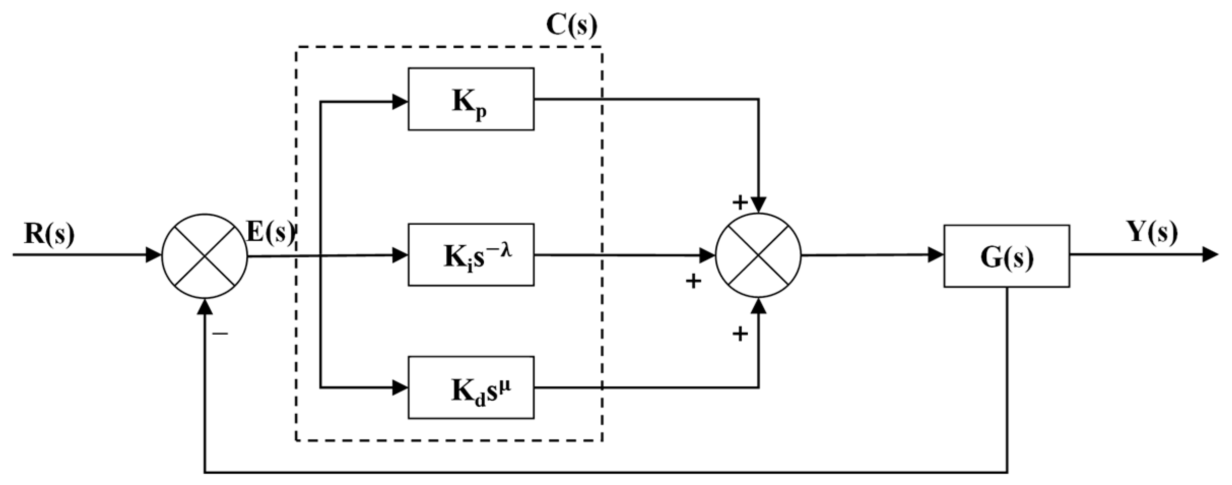
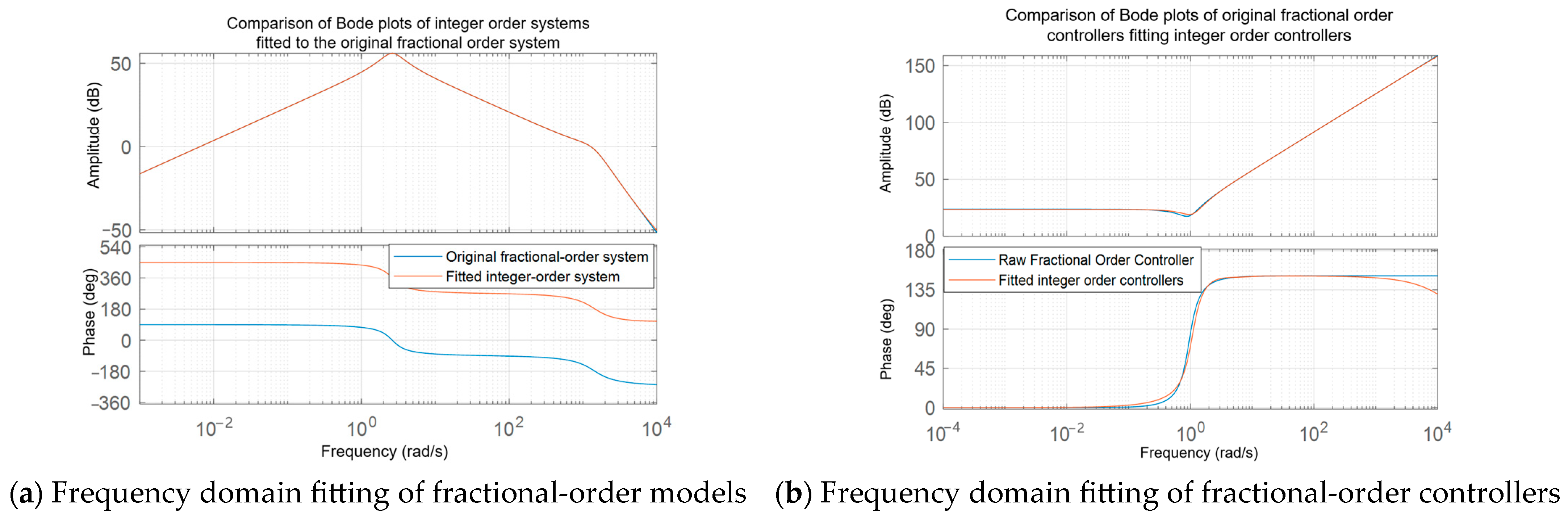
3.1. Fractional-Order Controller

In 1999, Professor Igor Podlubny introduced the application of fractional-order differential equations in automatic control, marking a significant advancement in control theory. Unlike conventional PID controllers, fractional-order controllers offer enhanced dynamic response characteristics and improved disturbance rejection capabilities, making them more adaptable to complex systems. The structural block diagram of the fractional-order controller is shown in Figure 3.
However, the performance of fractional-order controllers, including fractional-order PID (FOPID) controllers, heavily depends on the proper selection of their parameters. Conventional tuning methods, such as the Ziegler–Nichols and Chien–Hrones–Reswick methods, work well in simple systems, but often yield suboptimal results in complex non-linear systems, particularly when significant model inaccuracies are present [18,19]. Additionally, the parameter adjustment process is cumbersome, making it challenging to adapt to real-time changes in operating conditions. This limitation becomes even more pronounced for FOPID controllers, due to their higher-dimensional parameter space. To address these issues, many researchers have applied intelligent algorithms to the parameter tuning of PID and FOPID controllers. These algorithms offer significant advantages, including strong optimization capabilities, support for parallel computation, and effectiveness in multi-objective optimization. Therefore, this paper proposes the use of intelligent algorithms to optimize parameter tuning effectively.

3.2. Particle Swarm Optimization Algorithm Based on Improved Lévy Flight and Chaotic Mapping

Tuning the parameters of controllers, especially those with multiple parameters like fractional-order PID (FOPID) controllers, is a complex and challenging task. Manual tuning methods are often time-consuming and may not yield optimal parameter sets that guarantee high performance, particularly when the controlled system operates under varying conditions or in demanding environments. Intelligent optimization algorithms provide powerful tools for automatically searching the parameter space to find optimal or near-optimal controller gains that can significantly enhance system performance, robustness, and dynamic response. To effectively address these challenges and enhance the performance of the controller tuning process for the anchor drilling rig’s hydraulic system, particularly to ensure the high precision and strong robustness required for unmanned mining operations, this study proposes an enhanced Particle Swarm Optimization (PSO) algorithm incorporating multiple chaotic mappings and an improved Lévy flight mechanism [20]. This specific algorithm is designed to overcome the limitations of standard optimization methods by incorporating advanced search mechanisms tailored for complex parameter spaces.
Building upon the standard PSO algorithm, inspired by social behavior patterns such as bird flocking and fish schooling, which updates particle positions based on individual and global bests, ILPSO incorporates advanced mechanisms to improve search efficiency and convergence quality. For instance, the initial particle population is generated using chaotic mappings—Logistic, Tent and Chebyshev—to increase diversity and ensure a uniform distribution within the search space, preventing premature convergence in the early stages. The iterative equations for the chaotic mappings are as follows:
L o g i s t i c : x n + 1 = μ x n 1 x n T e n t : x n + 1 = 1 2 | x n 0.5
C h e b y s h e v :       x n + 1 = c o s k · a r c c o s x n
During the particle position update process, an adaptive chaotic perturbation mechanism is introduced, coupled with the Lévy flight strategy [21]. The Lévy flight mechanism is defined as follows:
Levy   flight :   L λ t λ s i n π λ 2
This dual mechanism enhances the global search capability and optimization precision of the PSO algorithm. To avoid local optima in complex search spaces, an Elite Reverse Learning (ERL) strategy is introduced. This step modifies the elite solutions to explore new regions of the search space by applying reverse learning principles. If no improvement is observed after several iterations, the Elite Reverse Learning mechanism adjusts the elite particle’s position, effectively guiding the search process towards better solutions.
The enhanced PSO algorithm combines chaotic perturbations and the Lévy flight strategy with the Elite Reverse Learning mechanism, ensuring efficient optimization of PID and FOPID controller parameters. The following figure, Figure 4, illustrates the flow of the enhanced PSO algorithm in collaboration with the FOPID controller, highlighting the key steps, including parameter initialization, chaotic mapping, Lévy flight, and Elite Reverse Learning.

4. Mathematical Modeling and Simulation Test

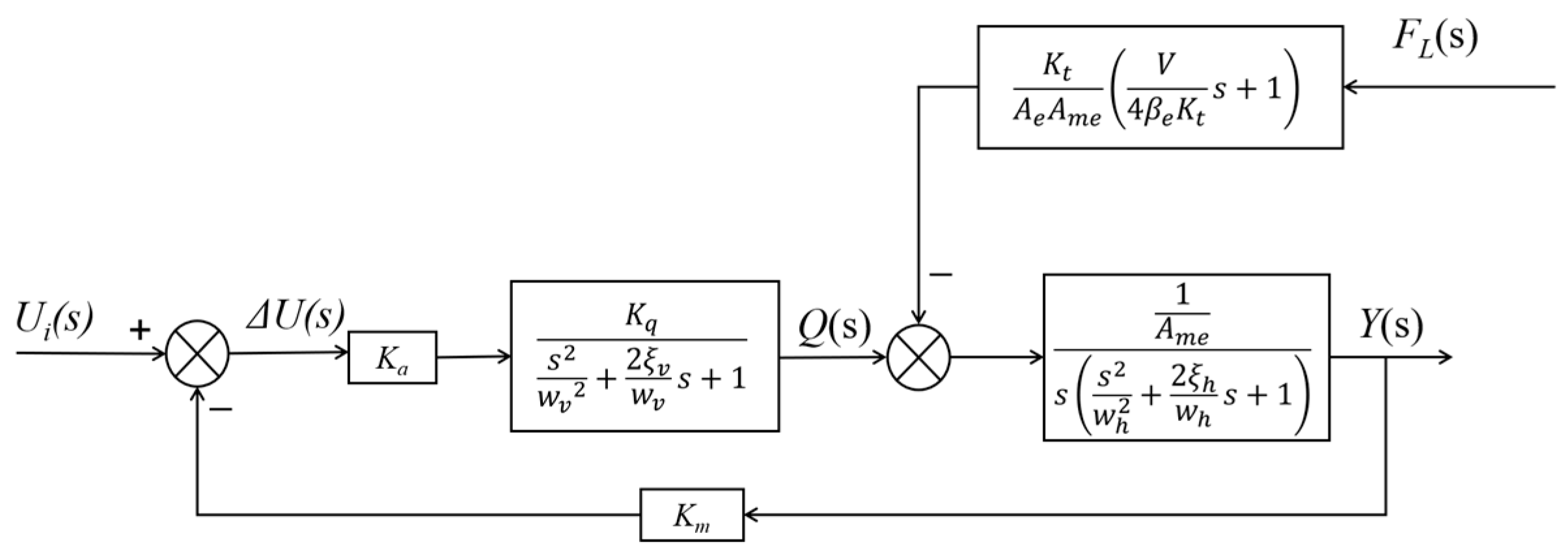
4.1. Modeling of Middle Valve-Controlled Hydraulic Cylinder

This study focuses on the electro-hydraulic cylinder at the center of the robotic arm driven by the drill rig, aiming to improve its control accuracy for precise alignment of the drill rod with the power head. The transfer function model for the position control of the electro-hydraulic proportional valve-controlled hydraulic cylinder, shown in Figure 5, is used [22]. A typical small hydraulic cylinder and proportional valve (Bosch 4WRPEH6, manufactured by Bosch Rexroth (Changzhou) Co., Ltd., located at No. 17 Longmen Road, Wujin National High-Tech Industrial Development Zone, Changzhou, China) are selected, considering a 50 kg equivalent load. The system parameters are obtained from specifications, as detailed in Table 1.
Based on the identification using the data from Figure 5 and Table 1, the transfer function of the valve-controlled hydraulic cylinder is obtained as follows:
G ( s ) = K α K q s 2 ω s v 2 + 2 ξ s v ω s v s + 1 A s s s 2 ω h 2 + 2 ξ h ω h s + 1   = 1 s ( 5.9 × 10 10 s 3.9449 + 1.81 × 10 6 s 3.0001 + 9.6 × 10 4 s 1.9923 + 1.6 × 10 3 s 1.0001 + 0.006 )
A simulation model of the hydraulic system with an FOPID controller was constructed in MATLAB-Simulink (Version 2023a). For this fractional-order controlled object, optimal PID, PIλDμ, and PIDμ controllers were designed. The step response curves of the systems with these controllers are shown in Figure 6.
The results indicate that the optimal integer-order PID controller exhibits significant oscillation, noticeable overshoot, and relatively slow convergence in the initial step response. In contrast, both fractional-order controllers demonstrate faster response speeds and smaller oscillation amplitudes, indicating that they outperform the integer-order PID controller in terms of dynamic characteristics and steady-state accuracy.

4.2. Performance Metric Function Evaluation

The performance of control systems is typically evaluated using metrics such as Integral of Squared Error (ISE), Integral of Absolute Error (IAE), Integral of Time-Weighted Squared Error (ITSE), and Integral of Time-Weighted Absolute Error (ITAE) [23]. These metrics aim to minimize errors and improve the performance of the FOPID controller. The evaluation formulas for these metrics are as follows:
I S E = 0 e 2 ( t ) d t , I A E = 0 x e ( t ) d t , I T S E = 0 t e 2 ( t ) d t , I T A E = 0 t e ( t ) d t
This study compares four algorithms—WOA, GWO, PSO, and ILPSO—as benchmark optimization methods to assess the control system’s performance [24,25,26]. These algorithms are evaluated based on performance metrics like ITAE, ISE, ITSE, and IAE, which aim to minimize accumulated errors over time.
As shown in Figure 7, the WOA algorithm excels with time-weighted error functions such as ITAE and ITSE, showing rapid convergence in early iterations, though it performs less effectively with ISE and IAE. The GWO algorithm performs best under ITAE, with fast convergence and the lowest final fitness value, making it ideal for high dynamic response tasks, but is weaker with ISE. PSO shows the lowest fitness value for ITAE but converges slower; it performs well with IAE and ITSE, stabilizing quickly in early iterations. ILPSO achieves low final fitness values and fast convergence for both ITAE and IAE, offering a balanced global and local search, though it underperforms with ISE.

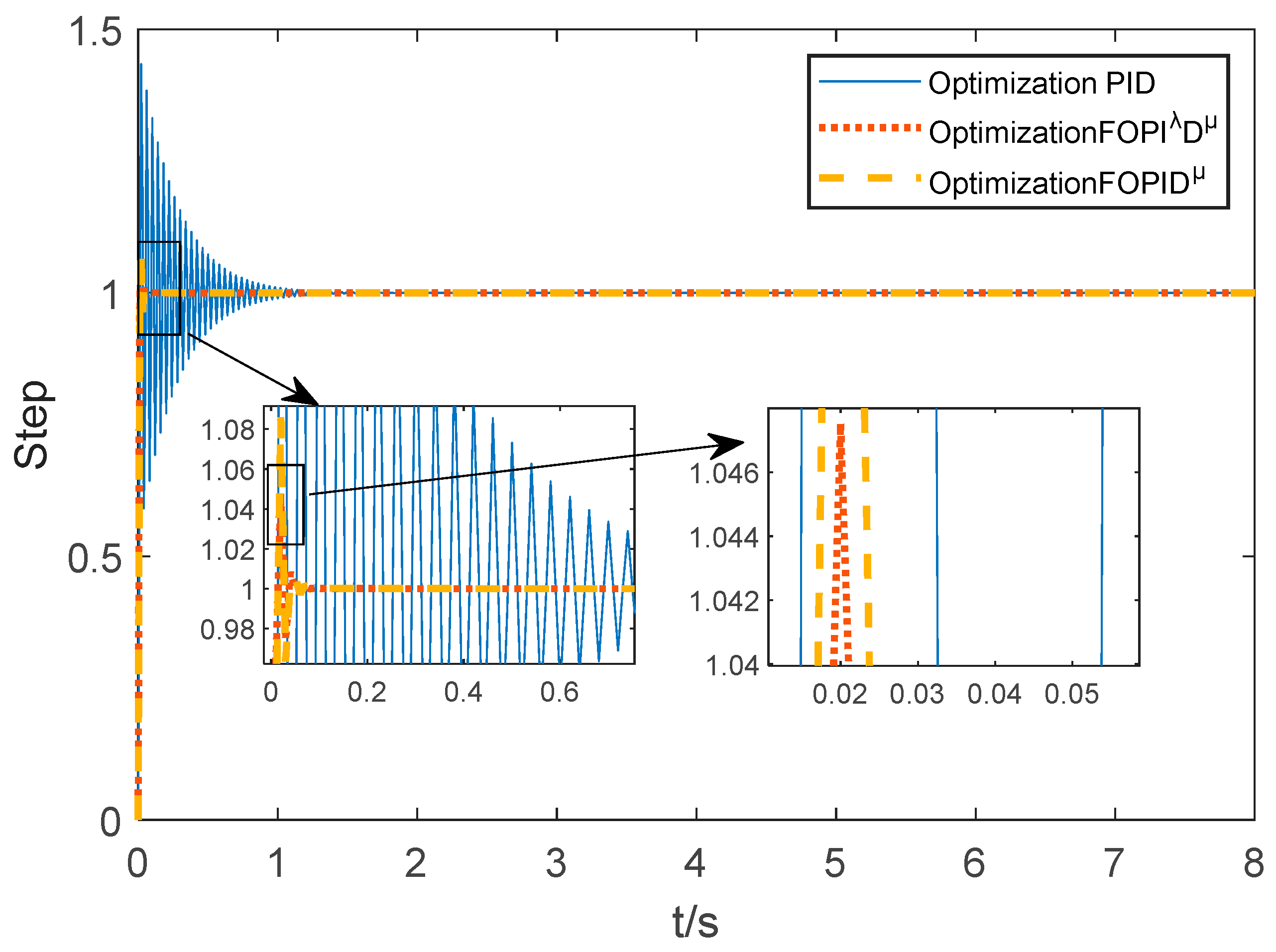
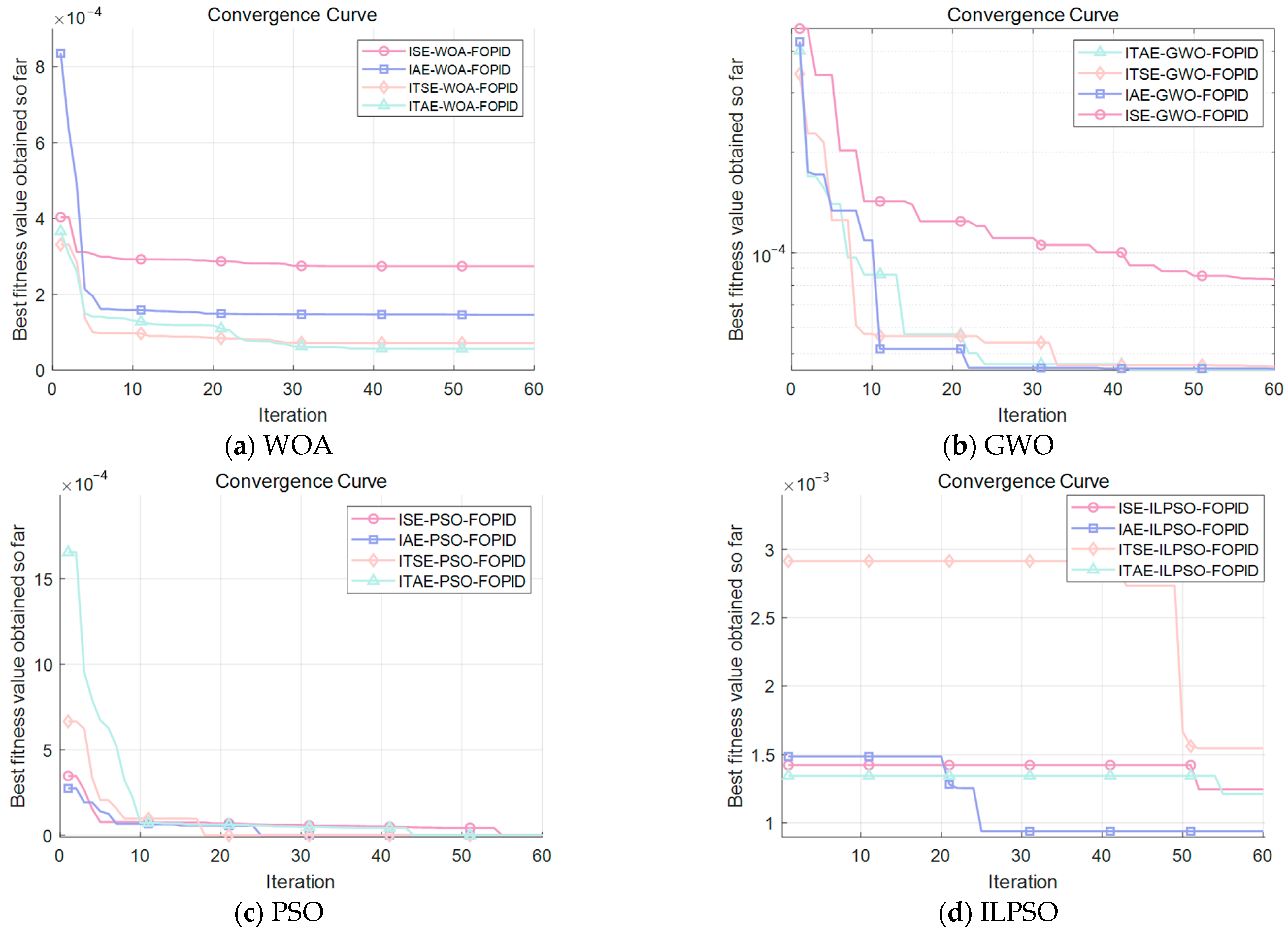
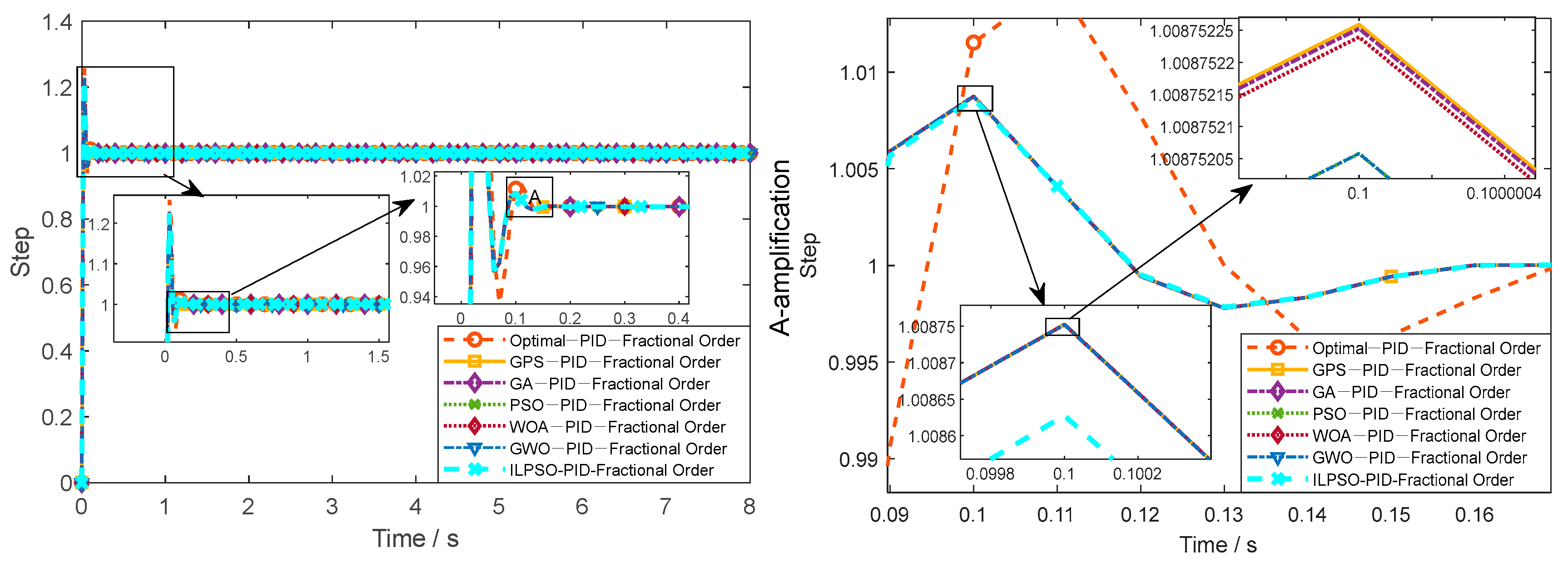
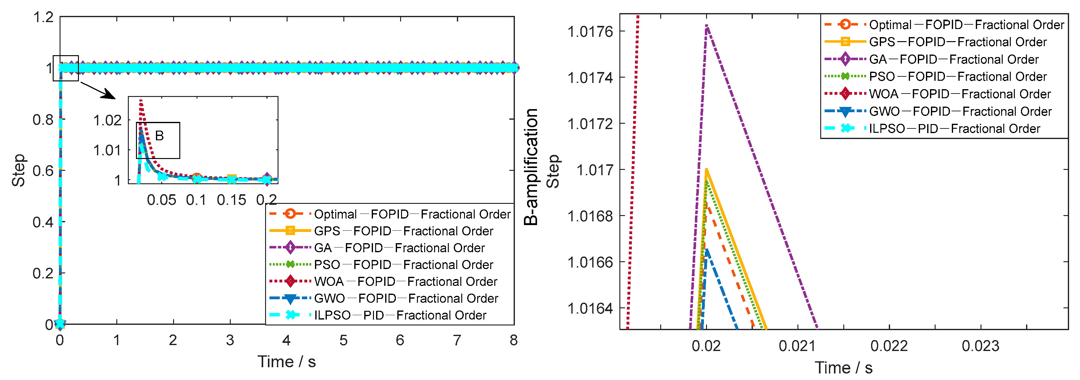
4.3. Simulation of Integer-Order and Fractional-Order Controllers Based on Intelligent Algorithms

The electro-hydraulic servo model established above was simulated in MATLAB–Simulink using intelligent optimization algorithms. Based on preliminary tests, a population of 30 search agents and an iteration limit of 60 were chosen. The selection of 30 agents offered an effective balance between sufficient exploration and computational efficiency. The iteration limit of 60 was set because preliminary runs indicated short computation times without significant improvement in dynamic parameters beyond this number, aligning well with the requirements of embedded real-time control in mining environments. Optimization parameter bounds for the PID controller were set from [0] to [20], and for the fractional-order PID (FOPID) from [0] to [2,20]. These ranges were informed by engineering knowledge of typical hydraulic servo controllers and preliminary algorithm evaluations, ensuring that the search space was both feasible and likely to contain optimal solutions. The Integral of Time-Weighted Absolute Error (ITAE) was chosen as the fitness function because preliminary comparative experiments (Figure 7) showed its superior convergence behavior and ability to achieve lower final fitness values, indicating desirable transient responses (low overshoot and rapid settling) suitable for the hydraulic positioning system of the anchor drilling rig.
To validate the effectiveness of the proposed enhanced ILPSO algorithm and provide a clear rationale for its selection over other optimization approaches, a comprehensive comparative study was conducted. To ensure consistency in initial conditions, various intelligent optimization algorithms, including the standard PSO, GA, WOA, GWO, and GPS, were evaluated alongside the proposed ILPSO in tuning the parameters of both the integer-order PID and fractional-order FOPID controllers for the simulated anchor drilling rig hydraulic system. The dynamic performance metrics obtained from this comparative study are summarized in Table 2, and the step response curves are shown in Figure 8 and Figure 9. Figure 8 presents the step response for the tested algorithms with the PID control strategy, while Figure 9 shows the step response for the same algorithms with the FOPID control strategy.
This section presents a comparison of the system’s output response under different intelligent algorithms combined with both PID and FOPID control strategies. As shown in Figure 8 and Table 2, the step response of various intelligent algorithms with the PID control strategy demonstrates that the system generally exhibits overshoot values above 22% and settling times exceeding 0.07 s. In contrast, the FOPID control strategy, as shown in Figure 9 and Table 2, significantly improves these metrics by reducing overshoot to approximately 1–2% and shortening the settling time to below 0.02 s, which greatly enhances the system’s dynamic response and stability. The comparison between PID and FOPID control strategies indicates that FOPID consistently outperforms PID in both dynamic and steady-state performance. The reduction in overshoot and settling time is particularly notable, demonstrating the effectiveness of the fractional-order controller in improving system stability and response.
As demonstrated by the comprehensive comparative results presented in Figure 8 and Figure 9, and quantitatively summarized by the performance metrics in Table 2, the proposed ILPSO algorithm exhibits superior performance in optimizing controller parameters compared to other intelligent optimization methods investigated for this application, including the genetic algorithm (GA) and other tested swarm optimization algorithms. Specifically, when combined with the FOPID controller, the ILPSO-FOPID pairing achieved the most favorable dynamic response characteristics among all tested algorithm-controller pairings, exhibiting the lowest overshoot (1.186%), the shortest settling time (0.0098 s), and a very low standard deviation (0.013).
Achieving such minimal overshoot, a rapid settling time, and a low standard deviation is critically important for the hydraulic control system of an anchor drilling rig operating in a harsh, unmanned mining environment. These precise and stable dynamic performance indicators directly correlate with the system’s ability to accurately reach target positions with minimal oscillation, maintain stability, and respond quickly and reliably despite significant external disturbances, which is essential for ensuring the reliability, safety, and efficiency of automated support tasks in unpredictable underground conditions. Therefore, the results of this comparative analysis validate the effectiveness and clearly demonstrate the superiority of the proposed ILPSO algorithm, particularly over other tested GA and swarm optimization methods, for tuning controller parameters in this specific domain, providing strong evidence justifying its selection as the most suitable optimization method to meet the demanding performance requirements for unmanned anchor drilling operations.

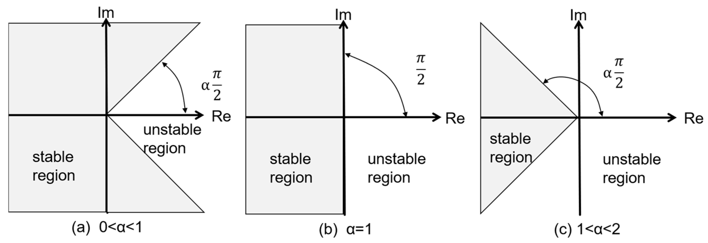
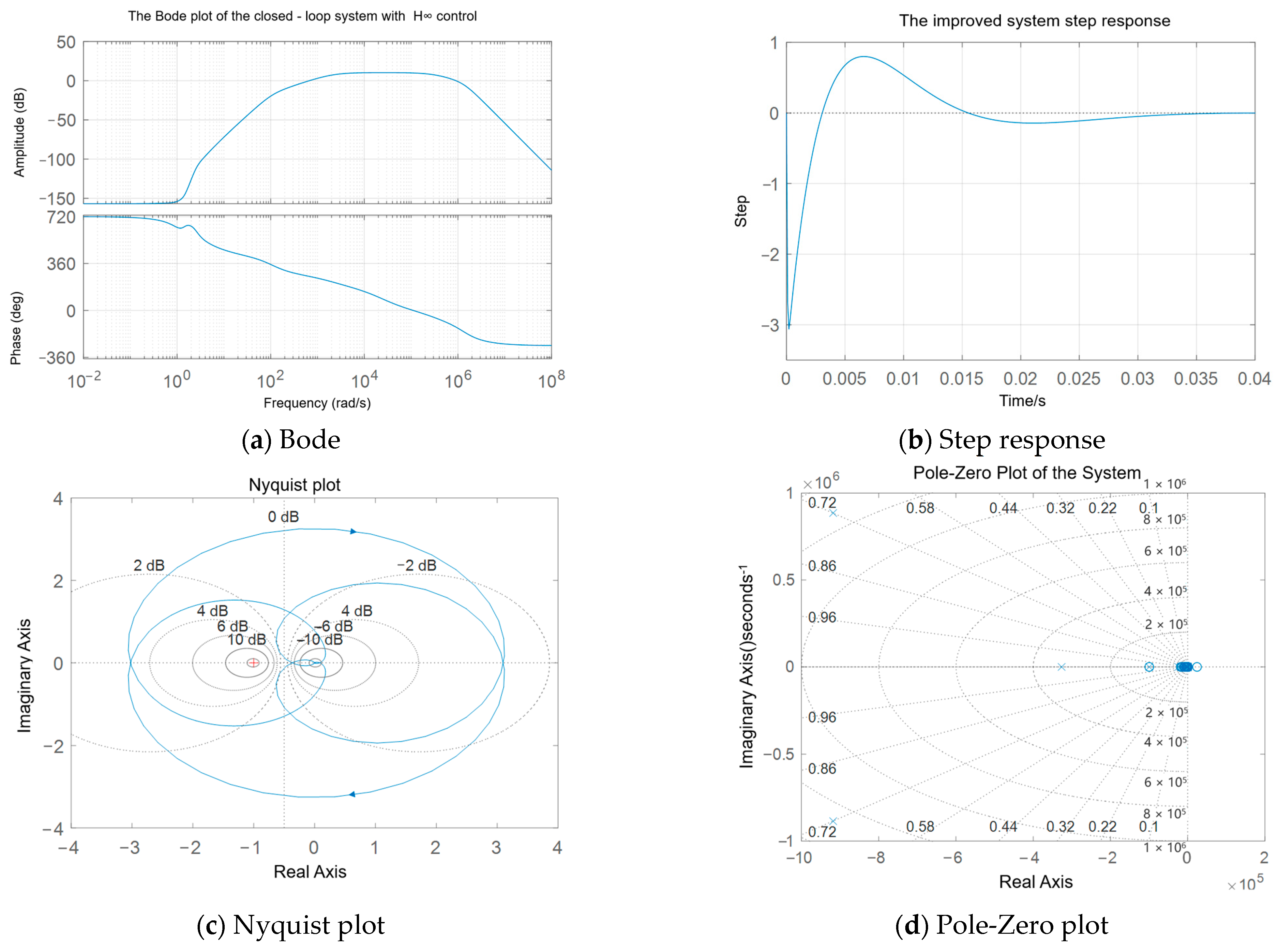
4.4. The Stability Analysis of the Model Under Fractional-Order Controllers

Stability analysis for fractional-order (FO) systems differs from traditional linear time-invariant (LTI) integer-order systems. While LTI system stability requires all characteristic equation poles to be in the left half of the complex plane, FO systems can exhibit stable behavior even with poles outside this region [27,28,29]. The stability is often assessed relative to a wedge-shaped region in the complex plane defined by the fractional order, α.
A key concept is Mittag–Leffler stability. A fractional-order dynamical system x ( t ) = A x ( t ) (where the derivative is fractional) is Mittag–Leffler-stable if its state trajectory x(t) decays towards zero bounded by the Mittag–Leffler function:
x ( t ) C E α ( γ t α ) , t t 0
where Eα(z) is the Mittag–Leffler function [See Equation (6)], γ > 0, and C > 0 depends on initial conditions.
E α ( Z ) = K = 0 Z K Γ ( α K + 1 ) , α > 0
Matignon’s Theorem provides a practical criterion for assessing the asymptotic stability (in the Mittag–Leffler sense) of an FO system represented by the transfer function G(s) = N(s)/D(sα). The system is stable if and only if all roots (poles) λj of the characteristic polynomial D(λ) satisfy the following:
arg Λ ( j ) > α π 2 , j
where 0 < α < 1 is the fractional order. This means all poles must lie outside the closed angular sector defined by ±απ/2, as illustrated conceptually in Figure 10.
We analyze the closed-loop system incorporating the fractional-order controller Gc(s) obtained via the ILPSO algorithm. The characteristic roots of the polynomial equation for the variable λ can be directly calculated, as shown in Figure 11. These poles also reside within the stable sector defined by Matignon’s criterion, with the closest pole having a slope of approximately 0.01816. Based on this numerical analysis, the closed-loop system appears to be Mittag–Leffler-stable.
However, this direct numerical root-finding approach for FO systems has significant limitations. Standard numerical solvers are designed for integer-order polynomials. Applying them to FO characteristic equations, often through polynomial approximation, can introduce substantial numerical errors. In this case, the reported root-finding error norm reached values as high as ~1040. Such large errors cast doubt on the accuracy of the computed pole locations and, consequently, the reliability of the stability assessment based solely on this method. Therefore, while indicative, this numerical result lacks rigorous theoretical robustness and should be interpreted with caution.
Due to the error accumulation problem when directly using integer-order methods to analyze fractional-order systems, this study adopts an improved frequency–domain fitting method based on frequency response. The optimal integer-order transfer function model is obtained by minimizing the error function. To further improve the fitting accuracy, a dynamic frequency band adjustment strategy is employed, where the start and stop frequencies of the band are adjusted according to the system’s dominant frequency [30]. The filter order N is increased to more precisely match the high-frequency response and enhance phase tracking capability.
The frequency–domain comparison of the approximate model and controller with the original fractional-order object is shown in Figure 12. The high-order integer-order approximate model effectively replicates the magnitude–frequency characteristics of the original fractional-order model. The phase difference of 360° is considered equivalent due to its periodic nature. The frequency response of the approximated integer-order controller also matches that of the original controller well, with small-magnitude errors in the main frequency band and phase deviations kept within ±5°. Although there is slight phase lag in the high-frequency range, the overall fitting performance is satisfactory.
We now analyze the stability of the approximated closed-loop system in the frequency domain. The Bode plot is shown in Figure 13.
As shown in Figure 13, the gain is near 0 dB in the low/middle frequencies but shows a relatively low amplitude overall, suggesting signal attenuation. There is a slight gain increase at high frequencies, potentially amplifying noise. The phase remains near 0° at low frequencies and shows insufficient phase compensation across the relevant frequency range. The frequency–domain analysis highlights potential stability concerns despite the earlier numerical pole analysis suggesting stability. The low phase margin indicated by the phase response staying near 0° suggests poor robustness to disturbances and potential instability. The high-frequency gain increase indicates susceptibility to high-frequency noise amplification. These findings suggest that while the system might be nominally stable according to pole locations, its practical stability margins are inadequate, necessitating further controller refinement or compensation to improve robustness and performance.
To enhance the anchor drilling machine’s robustness against disturbances and model uncertainties under complex operating conditions, particularly those identified during frequency analysis, the H∞ control methodology is employed [31]. The objective is to synthesize a feedback controller u(t) = Kx(t) that minimizes the H∞ norm of the disturbance-to-output transfer function (Tyw) below a specified threshold γ (||Tyw||∞ < γ).
T ( s ) = sup ω R σ max T ( j ω )
For this purpose, the existing FOPID controller combined with the plant is treated as a generalized plant for H∞ synthesis. Sensitivity (W1) and control (W2) weighting functions are introduced to shape the system’s response, attenuating external disturbances while limiting control effort for energy efficiency. Specifically, W1 primarily influences the controller’s ability to reject low-frequency disturbances and track commands, while W2 impacts the magnitude and bandwidth of the control input, affecting energy consumption and sensitivity to high-frequency noise. An optimal H∞ controller is then designed within this weighted framework. This design process often involves iterative tuning of the weighting function parameters; starting with initial parameters, the corresponding H∞ controller is synthesized, and the closed-loop performance is evaluated, particularly checking if the H∞ norm meets the requirement γ γ t a r g e t . The weighting function parameters are then adjusted based on this evaluation, and the process is repeated until satisfactory performance is achieved.
However, tuning the weighting functions and the H∞ controller introduced phase lag, potentially degrading performance. To counteract this, a triple-delay compensator was incorporated. The performance of the final system, after optimizing both the H∞ controller and the compensator, is evaluated and presented in Figure 14.
The Bode plot in Figure 14a indicates that the improved system maintains a stable, low gain in the low-frequency range, which significantly increases in the mid-frequency range (around 102 rad/s), demonstrating strong tracking performance. At high frequencies, the gain rapidly rolls off, providing substantial attenuation, which aids in mitigating the effects of external noise and rapid disturbances. Regarding the phase characteristics, the system exhibits approximately 720° of phase at low frequencies, gradually decreasing towards 180° as frequency increases, contributing to an enhanced phase margin. In the high-frequency region, the phase drops below −360°, reflecting the system’s high-frequency dynamic phase lag.
The Nyquist locus presented in Figure 14c does not encircle the critical point (−1, j0), confirming closed-loop stability, with a minimum gain margin of approximately 4 dB. Furthermore, the pole-zero plot in Figure 14d shows that all closed-loop poles reside in the left-half plane, and the dominant poles possess a damping ratio greater than 0.5, indicating good system stability.
The calculated H∞ norm of the system is 1.3. This signifies that the maximum singular value of the closed-loop transfer function is constrained below 1.3 across the entire frequency spectrum, ensuring that the maximum system output response to disturbances remains bounded. The disturbance rejection ratio, denoted as γ, is 2.3 dB, indicating the system’s capability to attenuate external disturbances to levels below 2.3 dB.
Although the improved system exhibits a significant phase lag, this resulting slower response beneficially prevents overshoot and oscillation, thereby enhancing mechanical stability. As observed in Figure 14b, the settling time remains around 0.02 s, indicating that the phase lag has a limited impact on overall system performance. Therefore, in the engineering application for the anchor drilling machine, accepting a moderate phase delay is a suitable trade-off for achieving enhanced disturbance rejection and stability.

5. Conclusions

This study addresses the demand for unmanned operations in coal mine roadway support by developing a novel anchor drilling rig. The rig integrates a chain-type anchor bolt magazine with a robotic manipulator, enabling automated anchor rod grasping and loading. The adoption of modular hollow self-drilling anchors combined with grouting significantly enhances the automation level of the drilling rig, improving operational efficiency and reliability.
To achieve precise anchor rod loading under unmanned conditions, we introduced a composite control strategy based on an improved particle swarm optimization (ILPSO)-optimized fractional-order proportional–integral–derivative (FOPID) controller. A fractional-order simulation model of the valve-controlled hydraulic cylinder in the rig’s robotic manipulator was established, and simulation experiments compared various algorithms and PID/FOPID controller combinations. Results demonstrated that the fractional-order FOPID controller achieves only 1–2% overshoot, significantly outperforming conventional PID controllers (over 22% overshoot), exhibiting enhanced disturbance rejection and faster response speeds (approximately 0.06 s reduction). Additionally, the ILPSO–FOPID combination exhibited superior dynamic performance compared to alternative algorithms.
Further stability and robustness analyses were conducted for the above system. Considering the vibration disturbances and varying loads typically encountered by drilling rigs, rapid response speeds could result in overshoot and mechanical impacts. Therefore, we introduced an outer-loop robust controller based on H∞ control theory. By slightly compromising response speed (increasing settling time to 0.1 s and the H∞ norm to 1.3), the system’s robustness and stability were significantly enhanced, rendering it more suitable for complex operating conditions.

Author Contributions

Conceptualization, J.Z. (Jun Zhang), J.L., J.X., W.S. and J.Z. (Jianzhong Zhao); methodology, J.Z. (Jun Zhang) and J.L.; validation, J.Z. (Jun Zhang), J.L., J.X., W.S. and J.Z. (Jianzhong Zhao); software, J.L.; formal analysis, J.Z. (Jun Zhang), W.S. and J.Z. (Jianzhong Zhao); investigation, J.Z. (Jun Zhang) and J.L.; writing—original draft preparation, J.Z. (Jun Zhang) and J.L.; writing—review and editing, J.Z. (Jun Zhang), J.X., W.S. and J.Z. (Jianzhong Zhao); supervision, J.X. and W.S. All authors have read and agreed to the published version of the manuscript.

Funding

The authors gratefully acknowledge the financial support from the National Key R&D Program of China (Grant No. 2024YFB471601), and the Shanxi Provincial Key Research and Development Program of China (Grant Nos. 202302100401009 and 202302100401010).

Institutional Review Board Statement

Not applicable.

Informed Consent Statement

Not applicable.

Data Availability Statement

All data generated or analyzed during this study are included in this published article.

Conflicts of Interest

The authors declare no conflicts of interest.

References

  1. Kang, H.; Gao, F.; Xu, G.; Ren, H. Mechanical Behaviors of Coal Measures and Ground Control Technologies for China’s Deep Coal Mines—A Review. J. Rock Mech. Geotech. Eng. 2023, 15, 37–65. [Google Scholar] [CrossRef]
  2. Xie, Z.; Zhang, N.; Qian, D.; Han, C.; An, Y.; Wang, Y. Rapid Excavation and Stability Control of Deep Roadways for an Underground Coal Mine with High Production in Inner Mongolia. Sustainability 2018, 10, 1160. [Google Scholar] [CrossRef]
  3. Yang, X.; Wu, D.; Zou, X.; Chen, H.; Zhang, S. An Analysis of Digging Anchor Machine Stability and Track Wear under Digging Conditions. Sci. Rep. 2022, 12, 17738. [Google Scholar] [CrossRef]
  4. Li, F.; Duan, B.; Sun, Y.; He, X.; Li, Z.; Wang, B. Quantitative Risk Assessment Model of Working Positions for Roof Accidents in Coal Mine. Saf. Sci. 2024, 178, 106628. [Google Scholar] [CrossRef]
  5. Onifade, M.; Said, K.O.; Shivute, A.P. Safe Mining Operations through Technological Advancement. Process Saf. Environ. Prot. 2023, 175, 251–258. [Google Scholar] [CrossRef]
  6. Gao, Z.; Guo, Z. Type Characteristics and Research Direction of Automatic Bolting Frame. Coal Sci. Technol. 2023, 51, 212–224. [Google Scholar] [CrossRef]
  7. Daunt, A. “Empower the Future”: Komatsu Unveils New Drilling and Bolting Rigs. Quarry, 17 May 2024. [Google Scholar]
  8. Kang, H.; Yang, J.; Jiang, P.; Gao, F.; Li, W.; Li, J.; Chen, H. Theory, Technology and Application of Grouted Bolting in Soft Rock Roadways of Deep Coal Mines. Int. J. Min. Met. Mater. 2024, 31, 1463–1479. [Google Scholar] [CrossRef]
  9. Zhang, J.; Liu, L.; Liu, C.; Sun, D.; Shao, J.; Li, Y. Research on Mechanism of Bolt-Grouting Reinforcement for Deep Fractured Rock Mass Based on Prestressed Anchor and Self-Stress Grouting. Rock. Soil. Mech. 2020, 41, 3651–3662. [Google Scholar] [CrossRef]
  10. Xie, M.; Li, Y.; Zhang, H.; Yang, Z.; Ren, Z.; Nie, R. Analysis of Drilling Vibration Characteristics of Anchoring System in Coal Mine. Sci. Rep. 2023, 13, 19236. [Google Scholar] [CrossRef]
  11. Liu, Q.; Zha, Y.; Liu, T.; Lu, C. Research on Adaptive Control of Air-Borne Bolting Rigs Based on Genetic Algorithm Optimization. Machines 2021, 9, 240. [Google Scholar] [CrossRef]
  12. Zhong, Q.; Zhang, B.; Bao, H.; Hong, H.; Ma, J.; Ren, Y.; Yang, H.; Fung, R. Analysis of Pressure and Flow Compound Control Characteristics of an Independent Metering Hydraulic System Based on a Two-Level Fuzzy Controller. J. Zhejiang Univ. Sci. A 2019, 20, 184–200. [Google Scholar] [CrossRef]
  13. Podlubny, I. Fractional-Order Systems and PI/Sup /Spl Lambda//D/Sup /Spl Mu//-Controllers. IEEE Trans. Autom. Control 1999, 44, 208–214. [Google Scholar] [CrossRef]
  14. Tepljakov, A.; Alagoz, B.B.; Yeroglu, C.; Gonzalez, E.A.; Hosseinnia, S.H.; Petlenkov, E.; Ates, A.; Cech, M. Towards Industrialization of FOPID Controllers: A Survey on Milestones of Fractional-Order Control and Pathways for Future Developments. IEEE Access 2021, 9, 21016–21042. [Google Scholar] [CrossRef]
  15. Lino, P.; Maione, G.; Stasi, S.; Padula, F.; Visioli, A. Synthesis of Fractional-Order PI Controllers and Fractional-Order Filters for Industrial Electrical Drives. IEEE/CAA J. Autom. Sin. 2017, 4, 58–69. [Google Scholar] [CrossRef]
  16. Hassan, F.; Zolotas, A. Impact of Fractional Order Methods on Optimized Tilt Control for Rail Vehicles. Fract. Calc. Appl. Anal. 2017, 20, 765–789. [Google Scholar] [CrossRef]
  17. Jiangbo, Z.; Junzheng, W. The Fractional Order PI Control for an Energy Saving Electro-Hydraulic System. Trans. Inst. Meas. Control 2017, 39, 505–519. [Google Scholar] [CrossRef]
  18. Birs, I.; Muresan, C.; Mihai, M.; Dulf, E.; De Keyser, R. Tuning Guidelines and Experimental Comparisons of Sine Based Auto-Tuning Methods for Fractional Order Controllers. IEEE Access 2022, 10, 86671–86683. [Google Scholar] [CrossRef]
  19. Tseng, K.-H.; Chung, M.-Y.; Chang, C.-Y.; Hsieh, C.-L.; Tseng, Y.-K. Parameter Optimization of Nanosilver Colloid Prepared by Electrical Spark Discharge Method Using Ziegler-Nichols Method. J. Phys. Chem. Solids 2021, 148, 109650. [Google Scholar] [CrossRef]
  20. Wu, Q. The Hybrid Forecasting Model Based on Chaotic Mapping, Genetic Algorithm and Support Vector Machine. Expert Syst. Appl. 2010, 37, 1776–1783. [Google Scholar] [CrossRef]
  21. Wang, T.; Xu, J.; Luo, W.; Yu, Y.; Huang, Z. A Novel Fruit Fly Optimization Algorithm with Levi Flight and Challenge Probability. Procedia Comput. Sci. 2021, 183, 182–188. [Google Scholar] [CrossRef]
  22. Yu, B.; Zhu, Q.; Yao, J.; Zhang, J.; Huang, Z.; Jin, Z.; Wang, X. Design, Mathematical Modeling and Force Control for Electro-Hydraulic Servo System with Pump-Valve Compound Drive. IEEE Access 2020, 8, 171988–172005. [Google Scholar] [CrossRef]
  23. Barisal, A.K. Comparative Performance Analysis of Teaching Learning Based Optimization for Automatic Load Frequency Control of Multi-Source Power Systems. Int. J. Electr. Power Energy Syst. 2015, 66, 67–77. [Google Scholar] [CrossRef]
  24. Zhang, J.; Wang, Y.; Che, L.; Wang, N.; Bai, Y.; Wang, C. Workspace Analysis and Motion Control Strategy of Robotic Mine Anchor Drilling Truck Manipulator Based on the WOA-FOPID Algorithm. Front. Earth Sci. 2022, 10, 954547. [Google Scholar] [CrossRef]
  25. Elghardouf, N.; Ennaciri, Y.; Elakkary, A.; Sefiani, N. Multi-Loop Active Disturbance Rejection Control and PID Control Strategy for Poultry House Based on GA, PSO and GWO Algorithms. Heliyon 2024, 10, e29579. [Google Scholar] [CrossRef]
  26. Benbouhenni, H.; Hamza, G.; Oproescu, M.; Bizon, N.; Thounthong, P.; Colak, I. Application of Fractional-Order Synergetic-Proportional Integral Controller Based on PSO Algorithm to Improve the Output Power of the Wind Turbine Power System. Sci. Rep. 2024, 14, 609. [Google Scholar] [CrossRef]
  27. Mughees, A.; Mughees, N.; Mughees, A.; Mohsin, S.A.; Ejsmont, K. Enhancing Stability and Position Control of a Constrained Magnetic Levitation System through Optimal Fractional-Order PID Controller. Alex. Eng. J. 2024, 107, 730–746. [Google Scholar] [CrossRef]
  28. Li, Y.; Chen, Y.; Podlubny, I. Mittag–Leffler Stability of Fractional Order Nonlinear Dynamic Systems. Automatica 2009, 45, 1965–1969. [Google Scholar] [CrossRef]
  29. Muresan, C.I.; Dutta, A.; Dulf, E.H.; Pinar, Z.; Maxim, A.; Ionescu, C.M. Tuning Algorithms for Fractional Order Internal Model Controllers for Time Delay Processes. Int. J. Control 2016, 89, 579–593. [Google Scholar] [CrossRef]
  30. Merrikh-Bayat, F. Rules for Selecting the Parameters of Oustaloup Recursive Approximation for the Simulation of Linear Feedback Systems Containing PIλDμ Controller. Commun. Nonlinear Sci. Numer. Simul. 2012, 17, 1852–1861. [Google Scholar] [CrossRef]
  31. Fiuzy, M.; Shamaghdari, S. Robust H∞-PID Control Stability of Fractional-Order Linear Systems with Polytopic and Two-Norm Bounded Uncertainties Subject to Input Saturation. Math. Comput. Simul. 2023, 208, 550–581. [Google Scholar] [CrossRef]
Figure 1. Structure of the intelligent drilling rig.
Applsci 15 05656 g001
Figure 2. Overall structure of the drilling and anchoring Robot.
Applsci 15 05656 g002
Figure 3. Intelligent optimization algorithm control system.
Applsci 15 05656 g003
Figure 4. Flowchart of the enhanced PSO algorithm for FOPID controller tuning. Wherein, the yellow modules represent the system modeling and error calculation phases; the green diamond indicates the determination of the early stopping condition; and the blue modules describe the elite reverse learning mechanism used for solution improvement.
Applsci 15 05656 g004
Figure 5. Position control model of electro-hydraulic proportional valve-controlled hydraulic cylinder.
Applsci 15 05656 g005
Figure 6. Step response curves of the system with optimal PID, PIλDμ, and PIDμ controllers. The black arrows highlight zoomed-in views (insets) of the response curves within the region demarcated by the black rectangular box, allowing for a more detailed examination of the system's behavior during this interval.
Applsci 15 05656 g006
Figure 7. Fitness curves of algorithms under different performance metrics. (a) Fitness curves of the WOA under different performance metrics; (b) fitness curves of the GWO under different performance metrics; (c) fitness curves of the PSO under different performance metrics; (d) fitness curves of the ILPSO under different performance metrics.
Applsci 15 05656 g007
Figure 8. The step response of various intelligent algorithms combined with the PID control strategy. Black boxes highlight key regions; arrows lead to insets for clearer comparison of algorithm responses. The right panel further enlarges region “A” to show fine details.
Applsci 15 05656 g008
Figure 9. The step response of each intelligent algorithm and FOPID combination strategy. Black boxes highlight key regions; arrows lead to insets for clearer comparison of algorithm responses. The right panel further enlarges region “B” to show fine-scale differences.
Applsci 15 05656 g009
Figure 10. Stability regions in the complex plane for different fractional orders α. (a) When 0 < α < 1, the stable region is narrower and closer to the negative real axis. (b) When α = 1, the boundary aligns with the imaginary axis, corresponding to classical integer-order systems. (c) When 1 < α < 2, the stable region expands, covering a wider angle around the negative real axis. The angle of the stable region is defined by απ⁄2.
Applsci 15 05656 g010
Figure 11. Region of stability for fractional-order systems.
Applsci 15 05656 g011
Figure 12. Comparison diagram in the frequency domain between the fitted model and the controller. (a) Comparison of Bode plots between the original fractional-order model and the fitted high-order integer-order model; (b) comparison of Bode plots between the original fractional-order controller and the fitted high-order integer-order controller.
Applsci 15 05656 g012
Figure 13. Fitting a closed-loop system response Bode plot.
Applsci 15 05656 g013
Figure 14. Robustness evaluation diagram of the closed-loop system with an H∞ controller and triple lag compensation; (a) Bode plot of the system with an H∞ controller; (b) step response of the system with an H∞ controller; (c) Nyquist plot of the system with an H∞ controller; (d) pole-zero plot of the system with an H∞ controller.
Applsci 15 05656 g014
Table 1. Mathematical modeling parameters of valve-regulated hydraulic cylinders.
ParametersParameter MeaningParameter ValueParameter Unit
A e Effective area of hydraulic cylinder piston 3.142 × 10 4 m 2
V 2 Hydraulic cylinder rod chamber volume 1.131 × 10 5 m 3
β e Integrated modulus of elasticity of oil 7 × 10 8 Pa
ρ Fluid density 850 kg / m - 3
B Piston and load viscous damping factor 628 N s / m
C i p Hydraulic internal leakage coefficient 5.0 × 10 12 m 5 / ( N s )
K a Amplifier gain 0.27 A / V
K c e Proportional directional valve flow–pressure coefficients 4.74 × 10 12 m 5 / ( N s )
K q Proportional directional valve flow Gain 4.8 × 10 2 m 3 / ( s A )
ω s v Proportional directional valves inherent frequency 75 rad / s
ξ s v Proportional directional valve damping ratio 0.5 -
ω h Intrinsic frequency of hydraulic cylinders 42.8 rad / s
ξ h Hydraulic cylinder damping ratio 2.3 -
Table 2. Control indicators of each intelligent algorithm and PID/FOPID combination strategy.
The Combination of AlgorithmsDynamic Performance Indices
Standard DeviationOvershoot (%)Settling Time (s)
Optimal—PID—Fractional Order0.0410525025.698806440.08686147
GPS—PID—Fractional Order0.0393516522.660748330.07672818
GA—PID—Fractional Order0.0393516522.660747070.07672817
PSO—PID—Fractional Order0.0393516222.660859040.07672776
WOA—PID—Fractional Order0.0393538322.660735680.07672815
GWO—PID—Fractional Order0.0393516222.660842470.07672839
ILPSO—PID—Fractional Order0.0109601922.523629130.07674312
Optimal—FOPID—Fractional Order0.035392541.685949870.01488788
GPS—FOPID—Fractional Order0.035392421.700062010.01487047
GA—FOPID—Fractional Order0.035396381.762676920.01494976
PSO—FOPID—Fractional Order0.035392281.695133690.01487006
WOA—FOPID—Fractional Order0.035352621.388778400.01274958
GWO—FOPID—Fractional Order0.035391801.665467520.01487959
ILPSO—FOPID—Fractional Order0.012755311.186140150.00977436
Disclaimer/Publisher’s Note: The statements, opinions and data contained in all publications are solely those of the individual author(s) and contributor(s) and not of MDPI and/or the editor(s). MDPI and/or the editor(s) disclaim responsibility for any injury to people or property resulting from any ideas, methods, instructions or products referred to in the content.

