Article

Research on Ground Directional Grouting Reinforcement Technology and Coupling Control of Fault Fracture Zone Through Rock Roadway

1
Beijing China Coal Mine Engineering Co., Ltd., Beijing 100013, China
2
School of Energy and Mining Engineering, China University of Mining and Technology-Beijing, Beijing 100083, China
*
Author to whom correspondence should be addressed.
Appl. Sci. 2025, 15(10), 5647; https://doi.org/10.3390/app15105647
Submission received: 7 April 2025 / Revised: 10 May 2025 / Accepted: 12 May 2025 / Published: 19 May 2025
(This article belongs to the Section Earth Sciences)

Abstract

:
The fault fracture zone has the characteristics of low strength and poor water resistance. These factors often lead to stress concentration and significant deformation during roadway excavation. In order to improve the anti-deformation ability and strength of the surrounding rock and reduce the support pressure, taking the roadway passing through the F2 fault in the Wugou coal mine as an example, the evolution characteristics of the surrounding rock of the roadway passing through the fault were studied using FLAC3D numerical simulation software, and the stress evolution law and failure characteristics of the surrounding rock in three stages of the roadway driving through the fault fracture zone were analyzed. The slurry diffusion characteristics under different grouting hole layouts were studied using COMSOL software, and the effectiveness of ground directional grouting (combined directional drilling technology with ground grouting technology) reinforcement technology was explored via similar simulation experiments. After the pre-grouting reinforcement of the surrounding rock by the ground directional hole in the field, the fault fracture zone was successfully excavated. The key technical system of the shield roadway passing through the fault based on the directional drilling and ground grouting technology was summarized and put forward. The three-hole drilling and the circumferential four-hole drilling layouts were used to realize the grouting in the fault fracture zone. Engineering practice shows that ground directional grouting has significant advantages and improves the mechanical properties of the broken weak surrounding rock. The deformation of the roadway roof is 128 mm, and the deformation of the two sides is controlled within 100 mm. This method greatly improves the stability of the roadway and has been verified by the field results.

1. Introduction

China’s coal seam occurrence conditions are complex, and a large number of coal mines are affected by faults [1]. Due to the influence of the fault fracture zone, the strength of rock mass is low, the degree of fracture development is high, and the tectonic stress is concentrated. The physical and mechanical properties of rock mass in this area are quite different from those in conventional conditions. When the roadway passes through, complex geological disasters are prone to occur, such as rock burst, water inrush, etc., resulting in large deformation and support problems of the roadway [2,3,4]. The rock roadway is generally a development roadway, and changing its layout will have a great impact on later production. Therefore, the rock roadway inevitably needs to pass through the fault structure in some cases. However, the traditional anchor cable support struggles to cope with the complex surrounding rock environment under the influence of geological effects, and the rock mass of the fault fracture zone cannot provide sufficient anchoring force for the anchor cable [5,6,7,8]. Therefore, it is of far-reaching significance to study the theory and technology of the rock roadway crossing the fault fracture zone.
With the increase in coal mining depth, the influence of geological structure on mining is also deepening [9]. In order to solve the influence of geological structure on coal mining, many scholars at home and abroad have carried out many studies. Kong et al. [10] explored the distribution characteristics of mining-induced stress and fault slip behavior in two mining directions. The cross-section shape of a roadway has an important influence on the stress distribution of the surrounding rock, especially the stability of the deep roadway. Li et al. [11] explored the instability characteristics of the surrounding rock in a deep surrounding rock roadway based on different cross-section shapes. Rong et al. [12] analyzed the influence of faults and ground stress on roadways and determined the main causes of large deformation of roadways under this geological condition. Zhang and Pan [13,14] studied the influence of geological structures such as faults on in situ stress and in situ rock stress of a roadway through various methods and analyzed the stress distribution characteristics and deformation law of a roadway under complex stress conditions. Aiming at the problem of large deformation caused by roadway excavation in gently inclined jointed rock mass, Wang et al. [15] studied the deformation characteristics of a roadway and the geomechanical properties of the surrounding rock. Shan et al. [16] studied the asymmetric deformation mechanism and control technology of the surrounding rock of a near-fault roadway. Lan et al. [17] studied the characteristics of fault activation in coal mines, analyzed the distribution law of a stress field, and realized the quantitative evaluation of fault activation degree. Guo et al. [18] studied the mechanism and influencing factors of rock burst under the condition of a composite fault structure.
Due to the influence of complex geological conditions, problems such as the large deformation of a roadway and grouting leakage appear [19,20]. The conventional support form of a roadway is difficult to meet the needs of safe production. In order to solve these problems, many scholars at home and abroad have carried out relevant research. Zhu et al. [21] conducted a comprehensive analysis of the fault-crossing roadway through numerical simulations and determined the best construction scheme to control the deformation of the surrounding rock. The influence of multi-fault distribution on the original tectonic stress of rock strata is complex. Kang et al. [22] proposed a method of long pipe pre-grouting and new grouting anchor cables for the support method of a roadway through the dense fault zone [22]. Wang et al. [23] studied the failure mechanism of a roadway through the fault fracture zone via in situ stress test technology. Wu et al. [24] proposed a synergistic control method of bolt–shotcrete–grouting for soft rock roadway support through mineral composition analysis. Wang et al. [25] developed a micro-crack grouting analysis and calculation program, which realized the quantitative description of the slurry diffusion range and the fracture development degree.
Due to the limitation of space, time, and required strength, the reinforcement measures of an underground roadway are sometimes difficult to completely solve many problems of a roadway passing through faults. Therefore, many scholars at home and abroad have studied the use of ground technology to solve the problem of roadway excavation caused by fault structures [26]. Ju et al. [27] used horizontal directional drilling grouting to seal water-conducting fractures. Li et al. [28] proposed the L-type directional branch hole structure for ground pre-grouting for the large roof pressure of the working face under the condition of thin bedrock, which provided a reference for the mining of similar working faces. Meng et al. [29] used geological prediction technology to determine the reasonable position of roadway crossing faults and proposed a curtain double-layer grouting technology by combining ground grouting and underground grouting.
However, there are still some deficiencies in the research on the stress evolution law of the surrounding rock and the arrangement form of grouting holes in roadways crossing the fault fracture zone. In this paper, through numerical simulations and theoretical analysis, the evolution characteristics of the surrounding rock and the influence of grouting hole arrangement and slurry diffusion in three areas of a roadway crossing the fault fracture zone are studied. The rationality of pre-grouting reinforcement technology in the fault fracture zone is studied using a similar simulation test. The ground directional grouting reinforcement technology is applied to shield the roadway passing through the fault, which solves the shortcomings of insufficient underground grouting diffusion range and limited space, improves the feasibility and rationality of ground directional drilling grouting technology, and has important practical significance for solving the influence of fault structures on roadway excavation.

2. Project Profile

2.1. General Geology

The mine structure of the Wugou coal mine is complex; the distribution of fault structure is complex, and the development degree is high. As shown in Figure 1, the F2 large normal fault is located in the middle of the three upper mining areas, and the mining area is divided into two parts: deep and shallow. The F2 fault is a large normal fault, strikes northeast, dips southeast, and dips 60~70°; the maximum drop is 80 m. The Wugou fault is a large normal fault with a nearly east–west strike, nearly dips to the north, and has a 60–65° dip angle, a 150 m maximum throw, and a 18~25 m fault throw at the roadway design position. The Wugou mine represents a typical case of fault-affected coal mining areas in China. Due to the influence of the fault fracture zone, the fracture development degree of rock mass is high, and the roadway is difficult to be excavated directly. This geological complexity underscores the need for reinforcement before excavation. According to the design of the mining area, two roadways will pass through the fault. According to the exploration geological report and three-dimensional seismic report data, there are risks of water damage and the fault fracture zone, and it is difficult to excavate and lacks follow-up support. In summary, in view of the safety hazards caused by the F2 fault and the Wugou fault, the research goal of this paper is to carry out ground pre-grouting reinforcement in the affected area of the fault fracture zone to ensure tunneling efficiency and support the difficulty of subsequent roadways.

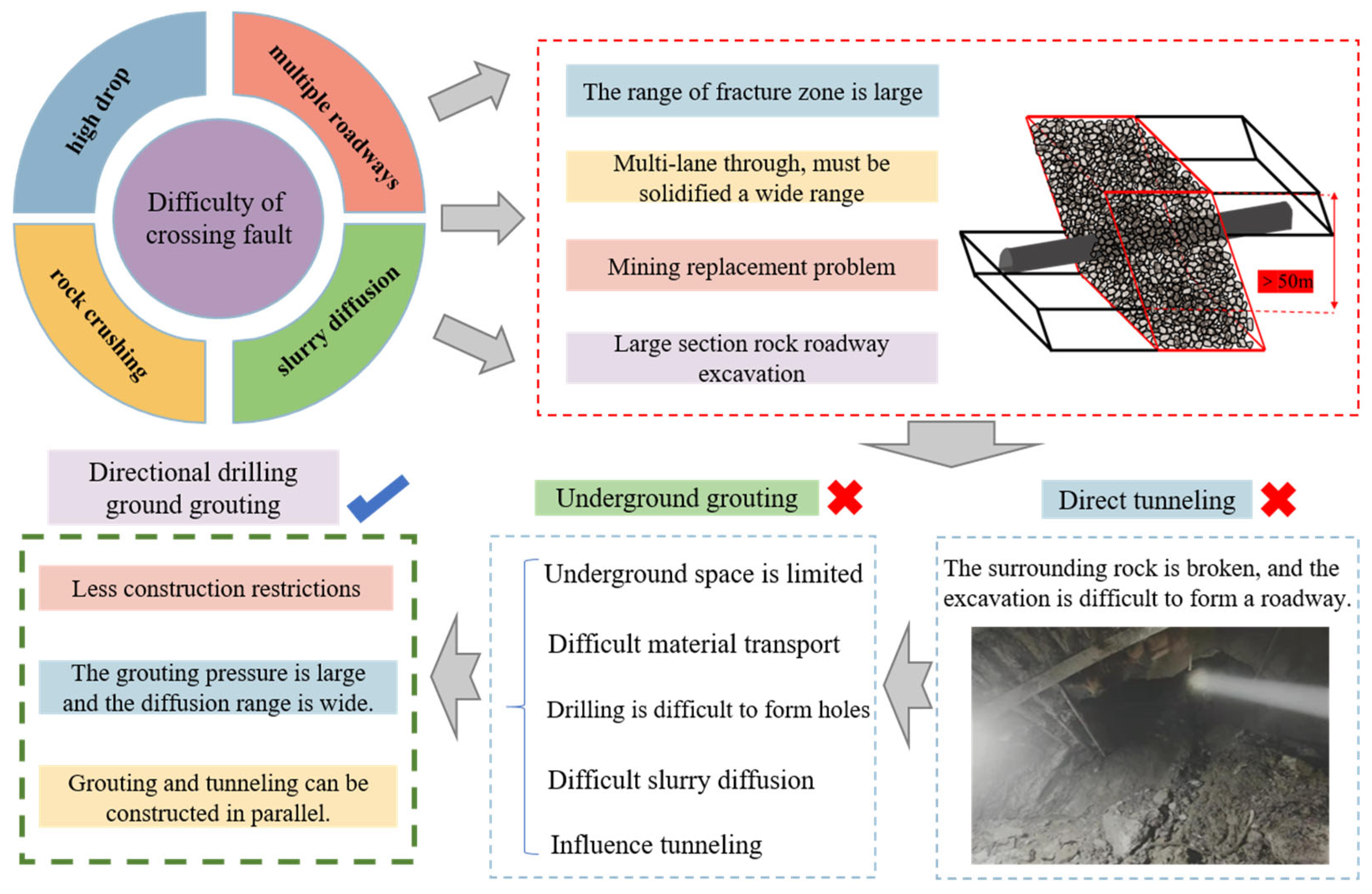
2.2. Technical Difficulties in Engineering

(1)
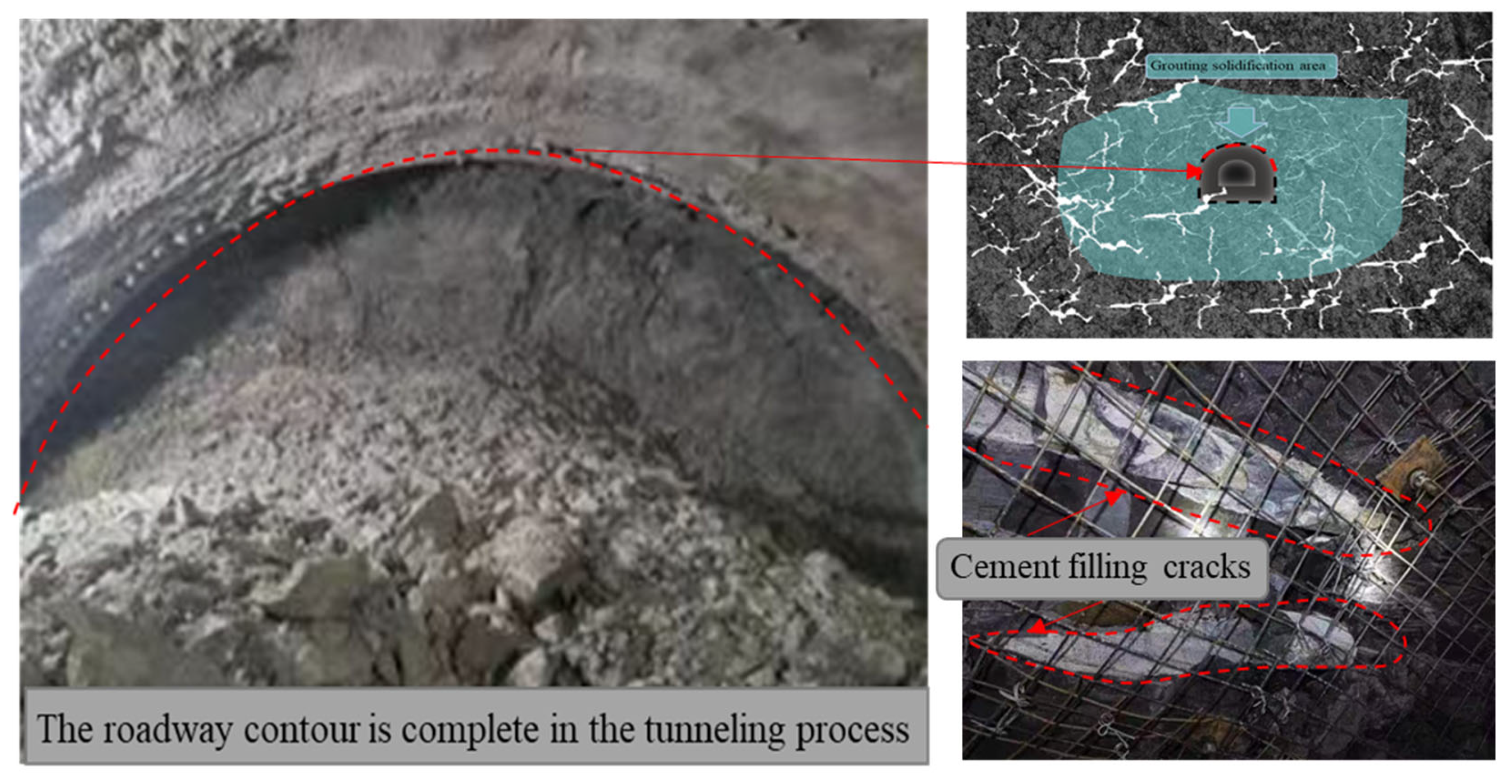
High difficulty of roadway formation: In the proposed control area, due to the influence of the fault fracture zone, the rock mass is broken, and it is difficult to form a roadway via direct excavation, and the subsequent maintenance is difficult.
(2)
Complex geological structure: Lianxiang needs to pass through the F2 fault and the Wugou fault, which have a large fault drop and a wide distribution of the fracture zone.
(3)
Difficulty of slurry diffusion: due to the influence of the fault fracture zone, the grouting slurry may run out of slurry, resulting in low grouting pressure that is unable to effectively reinforce the treatment area.
(4)
The excavated roadway is susceptible to grouting. Due to the close distance between the control area and the three uphill areas, it may cause adverse effects such as roof subsidence and floor heave.
In summary, there are many difficulties in the large-section rock roadway crossing the fault fracture zone, and the traditional underground grouting technology struggles to meet the demand. Therefore, it is necessary to pre-grout the fracture zone area through ground directional grouting. Difficulties and ground grouting advantages are shown in Figure 2.

3. Evolution Law of Surrounding Rock of Rock Roadway Crossing Fault Fracture Zone

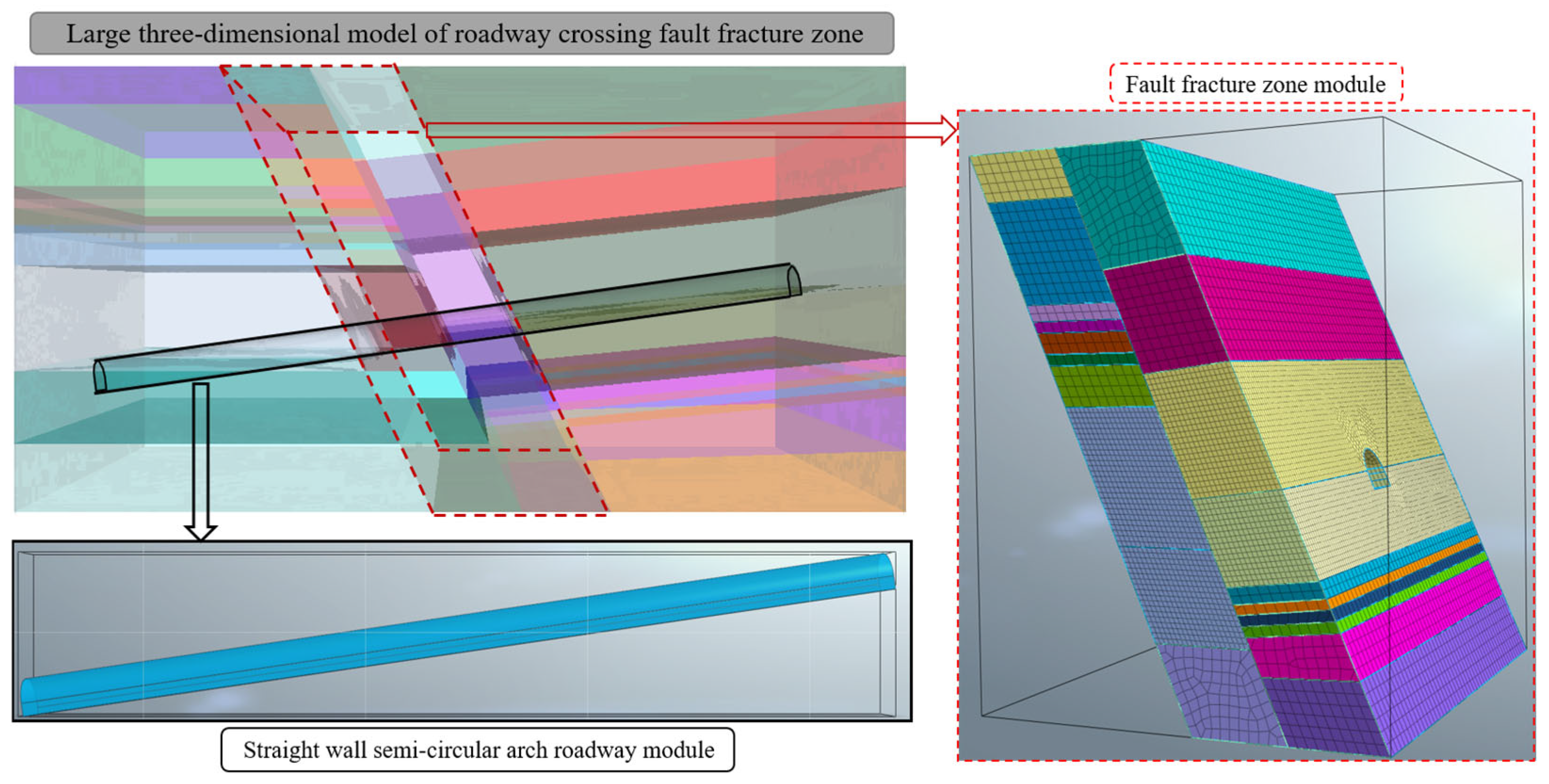
3.1. Three-Dimensional Model Construction of Rock Roadway Crossing Fault Fracture Zone

Based on the FLAC3D 7.0 software, a three-dimensional model of the joint roadway passing through the fault fracture zone is constructed (as shown in Figure 3). In the process of model construction, the fault fracture zone module is constructed by setting the contact surface and block, and the straight wall arch joint roadway module is constructed according to the actual engineering parameters. The model is used to explore the stress evolution law of the surrounding rock when the roadway passes through the fault fracture zone.

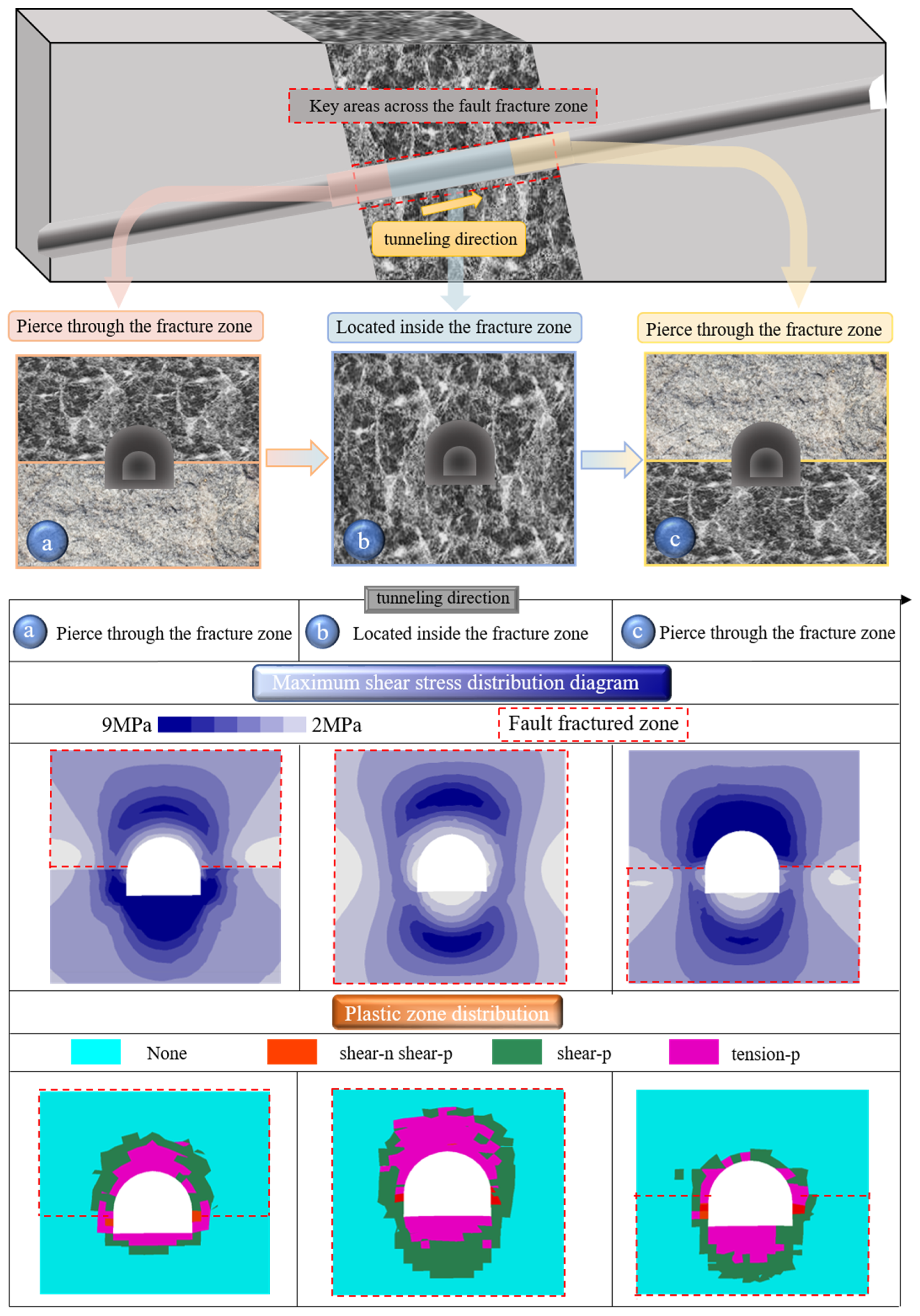
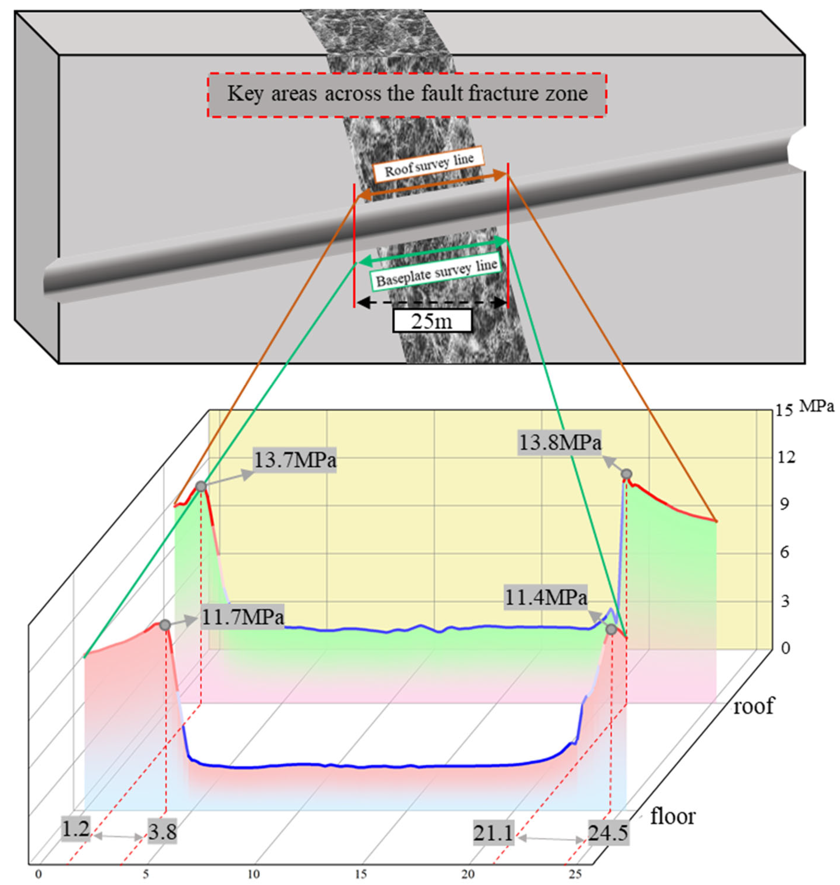
3.2. Gradient Evolution Law of Stress Partition of Surrounding Rock in Fault-Crossing Rock Roadway

In order to study the gradient evolution characteristics of the surrounding rock of the rock roadway crossing the fault fracture zone, the process of the roadway crossing the fault fracture zone is divided into three parts: pierce through the fracture zone, located inside the fracture zone, and pierce through the fracture zone, as shown in Figure 4a–c.
It can be seen from the maximum shear stress distribution cloud diagram that the stress distribution of the surrounding rock of the roadway in the three stages shows obvious differences. In the process of penetrating the fault, the roof of the roadway is destroyed, and the floor is completely in the high stress area. At this time, the distribution range of the plastic zone of the roadway roof is obviously larger than that of the floor. When the roadway is completely located in the fault fracture zone, the surrounding rock of the roadway is destroyed, and the plastic zone is distributed around the roadway. At present, tunneling and roadway maintenance are difficult. When the roadway passes through the fracture zone, the low stress zone appears in the roadway floor, and the plastic zone is mainly distributed in the roadway floor. Therefore, there are significant differences in the failure characteristics of the roadway surrounding rock in the three stages, and targeted measures should be taken in the actual excavation process.
The maximum shear stress of the roof and floor of the roadway is monitored by arranging the measuring lines at the same position. In the process of roadway excavation, the roof first enters the fault fracture zone. As shown in Figure 5, the shear stress of the roof decreases first, and the surrounding rock of the roof undergoes shear failure. At this time, the roof support should be paid attention to. As the roadway completely enters the fracture zone, the rock mass around the roadway is seriously damaged, and the excavation is difficult at this stage, and the roadway maintenance is difficult. In the process of the roadway passing through the fracture zone, the roof condition is improved before the floor.
In summary, in the three stages of roadway excavation through the fault fracture zone, there are significant differences in stress distribution and surrounding rock failure characteristics. Targeted measures should be taken according to their different characteristics to improve the rationality of excavation support.

4. Ground Directional Pre-Grouting Reinforcement Technology

4.1. Advantages of Ground Directional Pre-Grouting Technology

Compared with the traditional grouting reinforcement method, the advantages of ground directional grouting technology mainly lie in the following aspects: the construction environment, the construction time, and the grouting reinforcement effect.
As shown in Figure 6 below, the construction space using ground grouting technology is not limited. The transportation cost of materials is low, and the transportation volume is large, and the mixing of materials can be completed on the ground. Moreover, the ground grouting technology can be utilized in all weather conditions, with high efficiency and a short construction period. Before the rock roadway excavation has begun, the grouting operation is carried out in advance to reinforce the rock mass and ensure the safety and stability of the excavation operation. Due to the wide range of the fault fracture zone, the diffusion range of underground grouting struggles to meet the requirements, while the ground grouting pressure is large, and the slurry diffusion range is wide, which can form a high-strength grouting consolidation body and provide a strong guarantee for the safety and stability of subsequent tunneling operations.

4.2. Study on Similar Simulation Test of Pre-Grouting Reinforcement

The two-dimensional similar simulation test bench was used to study the reinforcement effect of ground directional pre-grouting on the roadway passing through the fault fracture zone. Model 1 simulates the fault fracture zone by increasing the material particle size and adjusting the material ratio during the material laying process. Model 2 constructs the same fault fracture zone as Model 1, and the grouting pipeline is embedded in the laying process. The test steps are shown in Figure 7.
Model 1 does not take any measures. Model 2 uses a high-pressure air gun to inject the pre-allocated cement slurry into the fault fracture zone through a pre-embedded grouting pipeline. After the cement slurry solidifies, the two models are excavated at the same time for roadway excavation. Since the overlying loading roadway excavation has not been carried out, the two model roadways are complete, and there is no significant difference. After the overlying load is loaded, the roadway in model 1 is completely destroyed, and the surrounding rock is broken, and the integrity of the roadway cannot be guaranteed during the actual excavation operation. Model 2 is reinforced by pre-grouting, and the slurry is fully diffused through the cracks, and the fault fracture zone is effectively reinforced. After overlying load loading, the shape of the roadway is complete, and only a small number of cracks are generated in the surrounding rock. In the actual excavation process, the difficulty of excavation is low, and the subsequent roadway maintenance is simple. Therefore, the ground pre-grouting reinforcement has played a significant role.

4.3. Key Technical Processes

4.3.1. Directional Drilling

Directional drilling is divided into three stages: firstly, the main hole passes through the straight hole section, enters the oblique section, and then enters the construction of each branch hole.
The drilling hole adopts the construction technology of a three-stage aperture and a two-stage casing. After the construction is completed, the drilling fluid is deployed to improve the lubricity of the drilling fluid; the casing is lowered; the circulation drilling fluid is used to ensure the connectivity in the casing ring cavity, and the cement slurry is used to fix the pipe and isolate it from the loose layer. In the second opening, the casing is run into the specified position, and the cement slurry is also used to fix the pipe. The third section is the bare hole section, which is drilled according to the design trajectory, as shown in Figure 8.

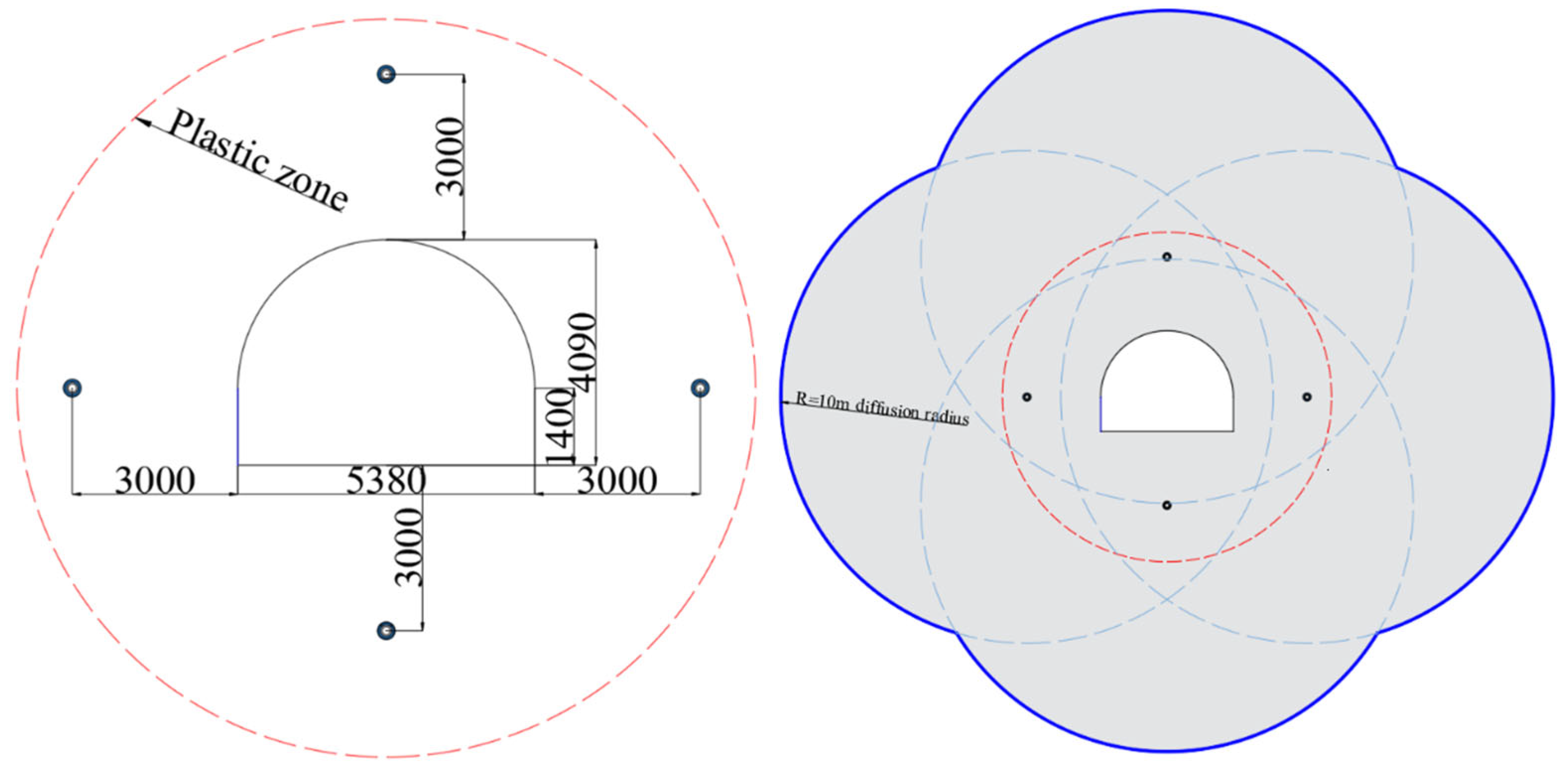
4.3.2. Grouting Hole Layout

The COMSOL 2022 software was used to explore the diffusion effect of the slurry under different grouting pipe arrangements. The pipeline arrangement includes three kinds of arrangement forms: a vertical double hole, a horizontal double hole, and an annular four hole, as shown in Figure 9.
The final slurry diffusion form of the vertical double-hole layout is similar to the vertical ellipse. At this time, the diffusion range of the slurry is narrow, which struggles to meet the reinforcement needs of the two-sided surrounding rock during roadway excavation. The final slurry diffusion form of the vertical double-hole arrangement is similar to the horizontal ellipse. As shown in Figure 9, when the roadway is located in the broken zone, the plastic zone around the roadway is widely distributed, and the plasticization of the surrounding rock at the top and bottom of the roadway is particularly serious. Therefore, the horizontal double-hole arrangement struggles to meet the reinforcement requirements. When the circumferential four-hole form is arranged in the form of four holes, the final slurry diffusion form is nearly circular; the distribution range is wide, and the cutting is uniform, and the surrounding rock of the subsequent roadway excavation is fully reinforced.
Figure 10 shows the distribution of grouting pressure under three kinds of grouting hole arrangements. Under the two arrangements of vertical double holes and horizontal double holes, the grouting pressure in the middle of the final two grouting holes is low, which is not conducive to grouting diffusion and consolidation strength. When the circumferential four-hole arrangement is adopted, the surrounding grouting pressure converges to the middle with the passage of time, which ensures slurry diffusion in the middle area and the strength of the consolidated body formed.
Therefore, through the above research on the slurry diffusion range and grouting pressure based on the three grouting hole layout forms, there are certain defects in the two double-hole layout forms, and the layout form of the circumferential four holes is more excellent, which can ensure the diffusion range of the slurry and the strength of the consolidated body, thereby improving the surrounding rock condition of the roadway excavation area and reducing the maintenance difficulty of the subsequent roadway.

4.3.3. Key Technology of Grouting

(1)
Slurry density selection: first, the slurry is used for trial injection to understand the size of the hole section grouting volume and the change in orifice pressure; then, the slurry concentration is adjusted.
(2)
Grouting pressure: Grouting pressure is the power source of grout diffusion in cracks, which should be adapted to the formation conditions, grout performance, and the required diffusion distance. When the grouting pressure is too small, the designed grouting diffusion distance cannot be achieved, and the grouting effect is poor. When the grouting pressure is too large, the diffusion distance is too large, resulting in unnecessary waste. Grouting adopts the grouting method of a ‘constant pressure variable’; that is, the fixed grouting pump volume is selected, and the slurry density is adjusted to make the actual grouting pressure ≥ the design grouting pressure, and the grouting pump volume is adjusted from large to small.
(3)
The criterion for the end of grouting: when the grouting pressure reaches 1.5 to 2.5 times the hydrostatic pressure, the pump volume is less than 60 L/min, and the stabilization time reaches 30 min, so the grouting process is completed.
(4)
Hole sealing: after the grouting of all branch holes, a single liquid cement slurry is used for grouting and sealing.
The ground directional pre-grouting reinforcement technology has a good effect on the shield roadway driving through the fault fracture zone, but this technology requires accurate geological exploration reports and directional drilling-related equipment.

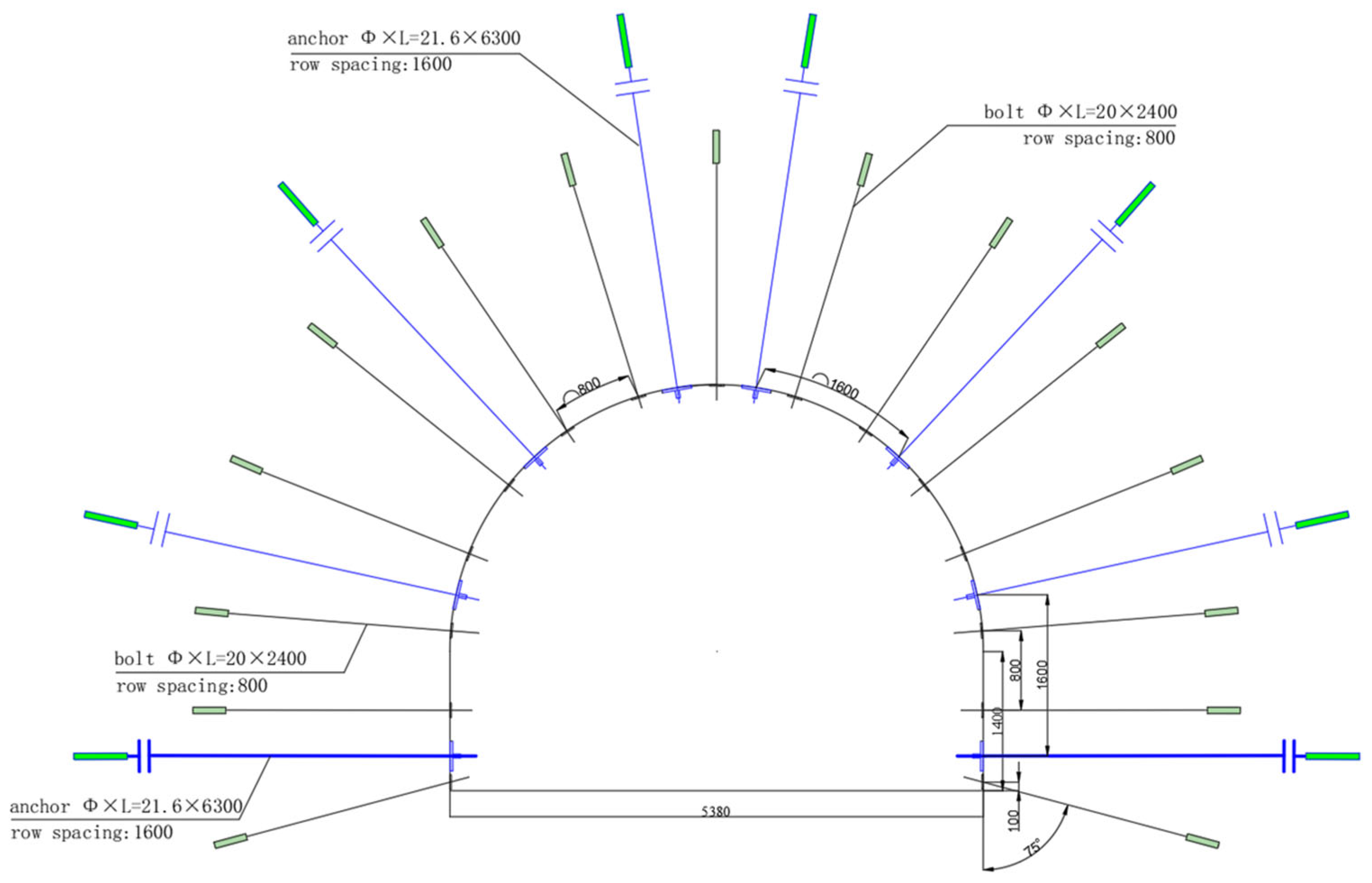
5. Control Technology of Surrounding Rock

As shown in Figure 11, the roof adopts 11 Φ20 mm × 2400 mm left-handed thread steel bolts, and the row spacing is 800 mm × 800 mm. The roof anchor cable adopts six ordinary anchor cables of Φ21.6 mm × 6300 mm, and the row spacing is 1800 mm. Two Φ20 mm × 2400 mm left-handed screw thread steel bolts are used for each side of the bolt. The bolt near the bottom plate has a 15° interpolation angle, and the row spacing is 800 mm × 800 mm. The anchor cable adopts a Φ21.6 mm × 6300 mm ordinary anchor cable. The roof is hung with metal mesh, the thickness of shotcrete is 15 cm, and the strength is c20.
For the anchoring composite bearing strength mechanical model, as shown in Figure 12, the anchoring composite bearing strength [30] is as follows:
q = 1 R 0 + L π ( R 0 + L ) 2 ( N 1 ) [ ( L π ( R 0 + L ) 2 ( N 1 ) ) ( π d 2 σ s 4 D a D b 1 + sin φ 1 sin φ + 2 c cos φ 1 sin φ ) + R 0 π d 2 σ s 4 D a D b + k 2 ( L π ( R 0 + L ) 2 ( N 1 ) ) 2 ]
where L is the length of bolt, measured in m;
N is the number of section bolts;
R0 is the roadway radius, measured in m;
Da and Db are the bolt spacing and row spacing, measured in m;
φ is the internal friction angle of rock mass in the anchorage composite bearing body, measured in °;
σs is the yield strength of bolt, measured in MPa.
The strength of the anchorage composite bearing body is calculated to be q = 2.13 MPa, which satisfies q > nγh (n is the safety factor, and h is the thickness of potential loose rock strata in the roadway roof), and the support scheme is reasonable.

6. Engineering Applications

6.1. Grouting Scheme

The layout of grouting holes adopts four annular holes, and the diffusion radius of single-hole grouting is 10 m so as to ensure that each hole has sufficient diffusion radius. After grouting, there is an overlapping circle range between the reinforcement ranges of each hole so as to ensure the grouting reinforcement effect within the plastic circle range of the roadway surrounding rock. The position of the hole is shown in Figure 13. The grouting material is a single liquid cement slurry.

6.2. On-Site Implementation and Monitoring

After the ground directional pre-grouting reinforcement, the roadway passed through the fault fracture zone safely and quickly. Excavation revealed that cement slurry filling was clearly visible in the cracks, as shown in Figure 14. The surrounding rock is stable when the roadway is excavated through the fault, and the excavation support effect is good, and the stability is high. The roof subsidence is 128 mm; the deformation of the left side is 98 mm; the deformation of the right side is 87 mm, and the maximum floor heave is 118 mm.
After grouting reinforcement, the integrity of surrounding rock is good, the roadway excavation is smooth, the support deformation is well controlled, and the long-term stability of the roadway is guaranteed.

7. Conclusions

(1)
Through the FLAC3D numerical simulation software, the model of a roadway crossing the fault fracture zone is constructed, and the stress evolution law of the surrounding rock of the roadway crossing the fault is explored. The three areas of the penetrating fault, which are located in the fault and penetrating fault zones, are analyzed emphatically, which provides a basis for roadway excavation and support.
(2)
The diffusion characteristics of the slurry under various grouting hole arrangements were explored using the COMSOL software, which provided a reference for the arrangement of grouting holes.
(3)
The ground directional pre-grouting reinforcement technology is proposed to effectively reinforce the fault fracture zone so that the roadway can be driven through the fault fracture zone quickly and safely. It enriches the technical means of roadway crossing faults and has important application value.

Author Contributions

Writing—original draft preparation, F.X.; software, Z.Z. and W.H.; conceptualization, D.C. All authors have read and agreed to the published version of the manuscript.

Funding

This research was supported with funding awarded from the Tiandi Technology Well Construction Research Institute independent science and technology project (Project number: KJZH-2024-JJZD-02).

Institutional Review Board Statement

Not applicable.

Informed Consent Statement

Not applicable.

Data Availability Statement

The original contributions presented in the study are included in the article. Further inquiries can be directed to the corresponding author.

Acknowledgments

Beijing China Coal Mine Engineering Co., Ltd. and Wugou Coal Mine have provided valuable on-site data and technical guidance for this study.

Conflicts of Interest

Authors Fuxing Xie and Wen He were employed by the company Beijing China Coal Mine Engineering Co., Ltd. The remaining authors declare that the research was conducted in the absence of any commercial or financial relationships that could be construed as a potential conflict of interest.

References

  1. Cao, D.; Zhan, W.F.; Li, H.; Li, X.; Liu, D.; Wei, Y. Tectonic setting and risk zoning of dynamic geological disasters in coal mines in China. J. China Coal Soc. 2020, 45, 2376–2388. [Google Scholar]
  2. Chen, D.D.; Wu, Y.Y.; Xie, S.; Guo, F.; He, F.; Liu, R. Reasonable location of stopping line in close-distance underlying coal seam and partition support of large cross-section roadway. Int. J. Coal Sci. Technol. 2020, 9, 55. [Google Scholar] [CrossRef]
  3. Wang, Q.Q.; Li, W.P. Application of directional borehole grouting technology to structural complex floor reinforcement in deep underground coal mine. Fresenius Environ. Bull. 2020, 29, 7208–7218. [Google Scholar]
  4. Zhao, Z.H.; Gao, X.J.; Ma, Q. Impact Hazard Assessment of Mine Roadway Excavation in Fault and Karst Erosion Area. In Proceedings of the 9th China-Russia Symposium “Coal in the 21st Century: Mining, Intelligent Equipment and Environment Protection”, Qingdao, China, 18–21 October 2018; Volume 176, pp. 54–62. [Google Scholar]
  5. Yang, Y.S.; Fang, Z.M.; Ji, G.; Zhao, B.; Wei, S. Study on Mechanical Properties and Control Technology of Surrounding Rock in the Fracture Zone of a Roadway. Shock Vib. 2021, 2021, 6628593. [Google Scholar] [CrossRef]
  6. Wang, S.G.; Ding, Z.D.; Shi, C.; Cai, H.; Chen, Y.; Ding, W.; Huang, J. Dislocation response of ECC-RC composite supporting structures of tunnels passing through active fault. Sci. Rep. 2024, 14, 15199. [Google Scholar] [CrossRef]
  7. Xie, S.R.; Li, H.; Chen, D.D.; Feng, S.; Yang, J.; Ma, X.; Jiang, Z.; Xing, S. Research on the Control Technology and Key Parameters of External Anchor-Internal Unloading of Surrounding Rock During Gob-Side Entry Driving Under Severe Mining of 1000-m-Deep Mine. Rock Mech. Rock Eng. 2024, 57, 2913–2932. [Google Scholar] [CrossRef]
  8. Wang, L.; Lu, W. A New Approach to Studying the Mechanical Characteristics of the Anchoring–Grouting System in Broken Surrounding Rock. Sensors 2023, 23, 8931. [Google Scholar] [CrossRef]
  9. Zu, Z.H.; Wang, W.J.; Zhao, F.J.; Wang, D.K.; Ye, Z.Y. Study on Combination Support for High Stressed Soft Rock Roadway. Prog. Min. Sci. Saf. Technol. Pts A B 2008, 7, 1642–1645. [Google Scholar]
  10. Kong, P.; Jiang, L.S.; Shu, J.; Wang, L. Mining Stress Distribution and Fault-Slip Behavior: A Case Study of Fault-Influenced Longwall Coal Mining. Energies 2019, 12, 2494. [Google Scholar] [CrossRef]
  11. Li, T.; Li, Z.; Liu, F. Study on Mechanical Characteristics of Rock Surrounding the Roadway under Different Section Shapes. Minerals 2022, 12, 1504. [Google Scholar] [CrossRef]
  12. Rong, H.; Guo, K.P.; Sun, D.; Luo, M.; Dong, W.; Huo, B. Research on main influencing factors and complete support technology for dynamic pressure and large deformation roadway. Sci. Rep. 2023, 13, 4136. [Google Scholar] [CrossRef] [PubMed]
  13. Zhang, B.; Zhou, H.Q.; Chang, Q.; Zhao, X.; Sun, Y. The Stability Analysis of Roadway near Faults under Complex High Stress. Sci. Adv. Civ. Eng. 2020, 2020, 8893842. [Google Scholar] [CrossRef]
  14. Pan, W.; Li, H.; Hua, X.; Liu, B.; Li, C. Research on grouting reinforcement technology of fault crossing roadway in fully mechanized mining face with large dip angle. Bull. Eng. Geol. Environ. 2024, 83, 216. [Google Scholar] [CrossRef]
  15. Wang, E.; Chen, G.B.; Yang, X.; Zhang, G.; Guo, W. Study on the Failure Mechanism for Coal Roadway Stability in Jointed Rock Mass Due to the Excavation Unloading Effect. Energies 2020, 13, 2515. [Google Scholar] [CrossRef]
  16. Shan, R.L.; Li, Z.L.; Wang, C.; Wei, Y.; Bai, Y.; Zhao, Y.; Tong, X. Research on the mechanism of asymmetric deformation and stability control of near-fault roadway under the influence of mining. Eng. Fail. Anal. 2021, 127, 105492. [Google Scholar] [CrossRef]
  17. Lan, T.W.; Liu, Y.H.; Yuan, Y.; Fang, P.; Ling, X.; Zhang, C.; Li, Y.; Li, Y.; Feng, W. Determination of mine fault activation degree and the division of tectonic stress hazard zones. Sci. Rep. 2024, 14, 12419. [Google Scholar] [CrossRef]
  18. Guo, W.H.; Cao, A.Y.; Hu, Y.; Xue, C.; Liu, Y.; Lv, D. Stress distribution and rockburst characteristics of roadway group under the influence of fault and fold structures: A case study. Geomat. Nat. Hazards Risk 2022, 13, 736–761. [Google Scholar] [CrossRef]
  19. Zhao, C.X.; Li, Y.; Liu, G.; Meng, X. Mechanism analysis and control technology of surrounding rock failure in deep soft rock roadway. Eng. Fail. Anal. 2020, 115, 104611. [Google Scholar] [CrossRef]
  20. Wang, E.; Yin, S.F.; Cheng, Z.; Xie, S.; Chen, L.; Kang, Q.; Duan, Y. Failure mechanism analysis of ultra-large-section soft-rock roadway in kilometer deep coal mine and its collaborative control of “grouting-anchoring-pouring”. Eng. Fail. Anal. 2025, 170, 109338. [Google Scholar] [CrossRef]
  21. Zhu, D.; Zhu, Z.D.; Zhang, C.; Dai, L.; Wang, B. Numerical Simulation of Surrounding Rock Deformation and Grouting Reinforcement of Cross-Fault Tunnel under Different Excavation Methods. Comput. Model. Eng. Sci. 2024, 138, 2445–2470. [Google Scholar] [CrossRef]
  22. Kang, Y.S.; Liu, Q.S.; Xi, H.; Gong, G. Improved compound support system for coal mine tunnels in densely faulted zones: A case study of China’s Huainan coal field. Eng. Geol. 2018, 240, 10–20. [Google Scholar] [CrossRef]
  23. Wang, K.; Wang, L.G.; Ren, B. Failure Mechanism Analysis and Support Technology for Roadway Tunnel in Fault Fracture Zone: A Case Study. Energies 2021, 14, 3767. [Google Scholar] [CrossRef]
  24. Wu, J.X.; Jiao, J.K.; Zhou, S.S. Controlling large deformations in soft rock roadways with integrated anchor shotcrete and grouting techniques. Sci. Rep. 2024, 14, 28339. [Google Scholar] [CrossRef]
  25. Wang, K.; Wang, L.G.; Ren, B.; Fan, H. Study on Seepage Simulation of High Pressure Grouting in Microfractured Rock Mass. Geofluids 2021, 2021, 6696882. [Google Scholar] [CrossRef]
  26. Qian, D.Y.; Zhang, N.; Zhang, M.; Shimada, H.; Cao, P.; Chen, Y.; Wen, K.; Yang, S.; Zhang, N. Application and evaluation of ground surface pre-grouting reinforcement for 800-m-deep underground opening through large fault zones. Arab. J. Geosci. 2017, 10, 285. [Google Scholar] [CrossRef]
  27. Ju, J.F.; Xu, J.L.; Yang, J. Experimental Study on the Flow Behavior of Grout Used in Horizontal Directional Drilling Borehole Grouting to Seal Mining-Induced Overburden Fractures. Geofluids 2021, 2021, 8823902. [Google Scholar] [CrossRef]
  28. Li, M.J.; Zhang, D.X.; Li, W.F.; Li, S. Research on Pre-Grouting Technology of upper Weathering and Oxidation plane of coal bed drilling by L-shaped Feather Branch Hole. Coal Eng. 2019, 51, 38–41. [Google Scholar]
  29. Meng, Q.B.; Han, L.J.; Qi, B.; Wen, S.; Chen, K.; Huang, X.; Sun, M. Study and application of key technology for roadway crossing faults under complex geological conditions. J. Min. Saf. Eng. 2017, 34, 199–207. [Google Scholar]
  30. Zhang, Y. Study on Bearing Characteristic of Composite Bolt-Rock Bearing Structure and Its Application in Roadway Bolting Design. Ph.D. Thesis, China University of Mining and Technology, Beijing, China, 2013. [Google Scholar]
Figure 1. The schematic diagram of the coal seam roof and floor.
Applsci 15 05647 g001
Figure 2. Technical difficulties in engineering.
Applsci 15 05647 g002
Figure 3. Roadway through fault fracture zone model.
Applsci 15 05647 g003
Figure 4. Stress evolution characteristics of the surrounding rock of the roadway passing through the fault fracture zone.
Applsci 15 05647 g004
Figure 5. Surrounding rock stress characteristic curve of the roadway crossing the fault fracture zone.
Applsci 15 05647 g005
Figure 6. Advantages of ground directional pre-grouting technology.
Applsci 15 05647 g006
Figure 7. Similar simulation experiment process of pre-grouting reinforcement.
Applsci 15 05647 g007
Figure 8. Directional drilling process.
Applsci 15 05647 g008
Figure 9. Evolution law of slurry diffusion range in various grouting hole layout forms.
Applsci 15 05647 g009
Figure 10. Grouting pressure evolution law of various grouting hole arrangement forms.
Applsci 15 05647 g010
Figure 11. Support scheme of the roadway.
Applsci 15 05647 g011
Figure 12. Strength mechanical model of the anchorage composite bearing body.
Applsci 15 05647 g012
Figure 13. Layout scheme of grouting holes.
Applsci 15 05647 g013
Figure 14. Site application effect.
Applsci 15 05647 g014
Disclaimer/Publisher’s Note: The statements, opinions and data contained in all publications are solely those of the individual author(s) and contributor(s) and not of MDPI and/or the editor(s). MDPI and/or the editor(s) disclaim responsibility for any injury to people or property resulting from any ideas, methods, instructions or products referred to in the content.

