Article

Parametric Analysis of Outrigger Systems for High-Rise Buildings with Different Geometric Shapes

Department of Structural and Geotechnical Engineering (DISG), Sapienza University of Rome, 00197 Rome, Italy
*
Author to whom correspondence should be addressed.
Appl. Sci. 2025, 15(10), 5643; https://doi.org/10.3390/app15105643
Submission received: 16 April 2025 / Revised: 13 May 2025 / Accepted: 16 May 2025 / Published: 19 May 2025
(This article belongs to the Section Civil Engineering)

Abstract

:
The increasing demand for efficient lateral load-resisting systems in high-rise construction necessitates the investigation of advanced structural solutions. Among many alternatives, outrigger systems are widely acknowledged as effective supplementary schemes for enhancing the strength and stability of tall buildings subjected to lateral loads. This work investigates whether the potential of such systems, well established for regular structures, also remains valid for the complex-shaped geometries that often characterize contemporary tall buildings. Tilted and twisted geometries are explored via the parametric variation of tilt and twist angles. The structural response, both with and without outriggers, is evaluated and compared to that of a regular geometry. The number, location, and relative stiffness of outriggers with respect to the inner core are also systematically varied to provide a comprehensive assessment. To facilitate the extensive parametric analysis, simplified analytical models are employed. Then, a selection of representative geometries are utilized to generate refined three-dimensional numerical models. A comparative survey between these two modeling approaches elucidates the accuracy and limitations of simplified methodologies, while providing insights into the structural behavior of outrigger systems. This work underscores the critical interaction between building configuration, outrigger location, and flexural stiffness in optimizing high-rise structural performance. The results reveal a significant influence of the building’s morphology on the structural response, with major improvements exhibited by regular and tilted configurations. Conversely, twisted geometries can considerably alter global structural behavior depending on their degree of twist, potentially diminishing the outrigger’s efficacy in mitigating lateral displacement and core base moment demands. By providing quantifiable insights into outrigger performance in complex-shaped structures, this research guides a more integrated architectural and structural approach in contemporary high-rise construction, leveraging an efficient simplified modeling framework for preliminary design.

1. Introduction

The rapid population growth since the early 20th century and increasing urban density, driven by rural-to-urban migration, have been primary catalysts for vertical urban expansion [1]. This demographic trend, alongside advancements in high-performance materials, construction technologies, and digital resources, has accelerated the global proliferation of high-rise buildings [2,3,4]. Historically, early skyscrapers prioritized efficient land utilization, maximizing usable floor space and minimizing structural weight for cost and material efficiency. Nowadays, these structures often serve as symbols of economic power and prestige, driving a competitive pursuit of the tallest and most iconic designs [3,5]. Contemporary architecture, indeed, increasingly features complex-shaped tall buildings, which embody a synthesis of aesthetic, aerodynamic, and structural principles. However, as building tallness increases, a “premium for height” must be paid due to amplified horizontal wind forces. Consequently, a paradigm shift from traditional structural systems to more efficient alternatives is required to withstand increased lateral demands. The critical demand for enhanced strength, stiffness, and stability has motivated innovative research on next-generation structural systems, exploring geometric unit cells for both façade grids [6,7,8,9] and spatial configurations [10]. Exhibiting high structural efficiency coupled with geometric versatility for non-orthogonal architectures, grid-like or tessellated typologies (such as Dia-grid, Penta-grid, Hexa-grid, Octa-grid, and Voronoi-grid) represent viable alternatives for lateral load-resisting systems of tall buildings with complex geometries. More recently, research efforts are increasingly directed towards the evaluation of optimal structural topologies aiming to identify designs that maximize performance-to-weight ratios. In this context, structural optimization methodologies constitute an effective tool for enhancing the design of tall buildings and identifying structurally efficient and innovative configurations, as demonstrated by application in multi-story frame structures [11,12].
A comprehensive review of prevalent structural solutions for tall buildings was conducted by Ali and Moon [13]. Their survey underscored the potential of core–outrigger systems for tall, super-tall, and mega-tall buildings. Generally speaking, lateral forces (whether from wind or seismic loading) induce both shear and bending stresses that structural systems must resist [14]. Primary lateral load-resisting systems, such as moment-resisting frames (MRFs) and core shear walls, are commonly utilized; however, they often lack sufficient lateral stiffness in high-rise buildings [15]. This has motivated the integration of supplementary secondary interior load-resisting systems, of which outrigger systems are a prominent example.
Outriggers are stiff, deep structural members—typically configured as auxiliary beams or trusses—that rigidly connect the high-rise building’s inner core to its perimeter columns. Under lateral loading, the outrigger system acts as a stiff horizontal cantilever, effectively restraining the core rotation by redistributing a portion of its overturning moment as additional axial forces in the perimeter columns. The mobilization of these members promotes the core’s stability [4]. The resulting tension–compression couple (with tension in the upwind and compression in the downwind columns) generates a resisting moment that counteracts core deformation. As observed by Lame [16], this mechanism increases the overall flexural stiffness while maintaining the building’s shear capacity largely unchanged. The enhanced rigidity yields reduced lateral displacement and bending moment demands, stabilizes the core’s base overturning moments, and improves occupant comfort. Belt-trusses are often employed to optimize axial force distribution across perimeter columns, reduce corner deflections at outrigger locations, and mitigate differential axial deformations (i.e., shortening and elongation) within the columns [17,18]. Essentially, the belt-truss ties the perimeter columns together, while the outrigger engages them with the central core. To ensure adequate flexural and shear stiffness, outriggers and belt-trusses are typically erected to a depth of one or two stories using steel, concrete, or composite materials. Unless explicitly defined otherwise, the combined outrigger and belt-truss system will be referred to as the “outrigger system” for the remainder of this paper. Figure 1 provides a schematic representation of a multi-level outrigger system integrated within an MRF structure with a central core. Key components labeled on the right-hand side include the following: core shear walls (primary vertical load-bearing elements), horizontal outrigger arms extending from the core at multiple levels and rigidly connected to outer perimeter columns, and a belt-truss connecting perimeter columns at outrigger levels.
Core–outrigger systems offer practical advantages in high-rise construction, including flexible exterior column spacing and simplified perimeter beam–column connections, enabling the construction of exceptionally tall structures, potentially exceeding 150 stories [15]. A primary design consideration, however, is the reduced floor area at the outrigger level, which often dictates their placement on mechanical floors. Yet, the number and placement of outriggers are critical design constraints that significantly influence the structural response to lateral load [19,20]. Extensive research has focused on the optimization of these parameters for enhanced performance. Studies have generally found optimal single-outrigger positions around mid-height [21,22,23,24], while multi-outrigger systems suggest placements at approximately one-third and two-thirds of the building height [23,25] or equidistant from the base [26]. The parametric analysis by Stafford Smith and Coull [27] further confirmed these trends, noting the superior drift and moment minimization achieved with a single mid-height outrigger and providing specific optimal placements for up to three outriggers. Boggs and Gasparini [28] also found that tapering core and column sections necessitates an upward shift in the optimal outrigger position due to increased stiffness demands at the upper levels.
Subsequent research has explored the influence of additional factors (such as lateral loading, column stiffness, span length, outrigger flexural stiffness, and building height) on the optimal number of outriggers. These studies indicate diminishing returns beyond four outriggers [29] and suggest two to three for effective drift control [30]. Furthermore, Fawzia and Fatima [31]’s investigation on steel outriggers highlighted the dependence of single- and double-outrigger effectiveness on their vertical position and the adverse impact of increasing height-to-width ratios on lateral stiffness in composite buildings.
Recognizing the complexity of outrigger system configurations, recent research emphasizes the need for optimized topology and size design for efficient structures. Key findings reveal that increasing the number of outriggers generally reduces top drift, inter-story drift, and core base moment, albeit with decreasing efficiency for each additional level [32,33,34,35]. In this context, the comprehensive review by Alhaddad et al. [36] provides guidelines on the optimum design of outrigger systems, illustrating the impact of design variables on the structural response.
Despite extensive research having explored outrigger systems in tall buildings, primarily focusing on parameters influencing efficacy and optimal vertical placement, studies addressing complex geometries remain limited. To the author’s best knowledge, Moon [37,38] made a major effort towards the understanding of outrigger performance in twisted, tilted, and tapered tall buildings. His study analyzed a 60-story building with a steel-braced core, mega-columns, and outrigger systems. Parametric analyses considered outriggers placed at the top and mid-height of the twisted tower, and at one-third and two-thirds of the height of the tilted and tapered towers. Comparisons in terms of lateral displacement revealed that lateral stiffness decreases with increasing twist, while it increases with taper and tilt.
The incomplete investigation of complex geometries represents a notable deficiency in the literature, especially in light of the contemporary architectural preference for such forms. To actively contribute in addressing such limitations, this study investigates the outrigger behavior in regular, twisted, and tilted high-rise composite buildings under lateral loading scenarios. The interaction of outrigger systems with RC core shear walls is explored via the parametric variation of key geometric and mechanical parameters to assess the outrigger’s effectiveness. Specifically, the number, placement, and relative stiffness of the outrigger system with respect to the inner core are systematically altered, along with twist and tilt angles. Comparative analysis of idealized analytical and refined models elucidates the accuracy and limitations of simplified methodologies while providing insights into the complex structural behavior of these systems.
The paper is structured as follows. Section 2 details the simplified modeling approach and discusses the parametric analysis results. Section 3 analyzes three refined models and compares the results with those obtained from the simplified models. Finally, Section 4 summarizes the key findings of this study.

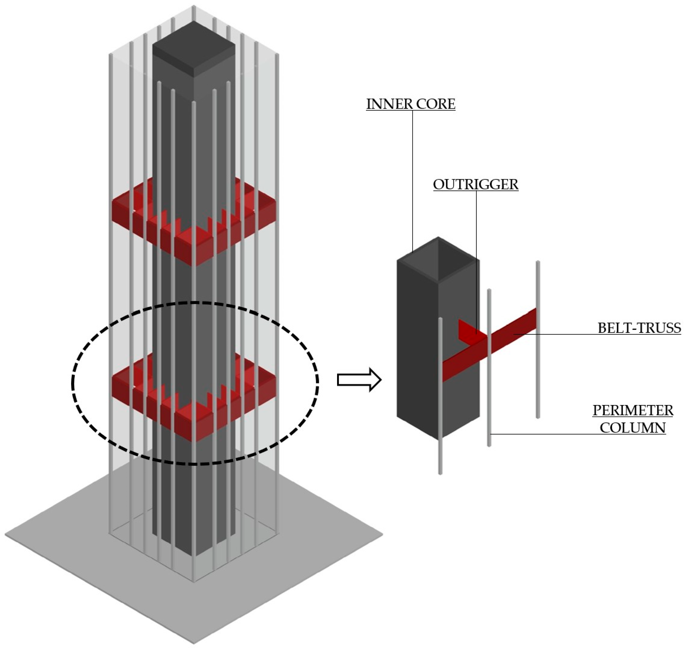
2. Simplified Approach for Outrigger Systems

2.1. Background

Outrigger systems in tall buildings are frequently analyzed using simplified continuum or discrete approaches. Early idealized continuum models, like those proposed by Taranath [39], represent the core as a cantilever beam with rotational springs at the outrigger levels, assuming infinite flexural stiffness for outriggers and belt-trusses. Subsequent research expanded upon this foundation. For example, Stafford Smith et al. [27,40,41] proposed a cantilever beam model with outriggers rigidly connected to the core and pinned to the exterior columns, assuming linear elastic behavior, axial forces in columns, and constant sectional properties along the building’s height. Hoenderkamp et al. [42,43] employed a graphical method with simply supported outriggers (pinned to both core and columns) for the preliminary design of high-rise steel structures with an RC core, outrigger-braced system, and non-fixed foundation conditions. Lee et al. [44,45,46] developed a refined two-dimensional model incorporating shear deformation in both outriggers and the core. Assumptions included linear elastic behavior, uniform member properties, rigid core–outrigger connections, pinned outrigger–column connections, and a fixed core base. Later research highlighted the significance of accurately representing core–outrigger relative stiffness. Zhang et al. [47] demonstrated that assuming infinite outrigger rigidity affects horizontal deflection and base moments, thus highlighting the significance of using actual outrigger stiffness in optimization analyses. Su et al. [48] investigated the load-transfer mechanism between outriggers and the core using the strut-and-tie method. Rahgozar et al. [49,50] developed an approximate method for framed tube, shear–core, and outrigger–belt-truss systems, focusing on the optimal location. Atkinson [51] employed a simplified model with an elastic core shear wall, rigid outriggers, and elastic columns to analyze dynamic behavior. More recently, Marabi et al. [52] proposed an idealized analytical model simplifying the outrigger frame system into a central cantilever core and a concentrated restoring moment from the outrigger.
This body of research demonstrates the evolution of modeling techniques, progressing from simple cantilever models to more sophisticated approaches. It is important to highlight that simplified analytical models provide a valuable basis for understanding the global behavior of outrigger systems and precede detailed finite element analyses. However, two main limitations can be identified. First, outriggers are typically discretized as elements with infinite flexural stiffness and assumed to be simply pin-connected to the columns. Second, these methods are primarily suited for estimating optimal outrigger placement for the drift minimization of regular structures. Consequently, such methods exhibit limited applicability to complex configurations involving geometric or material variations.

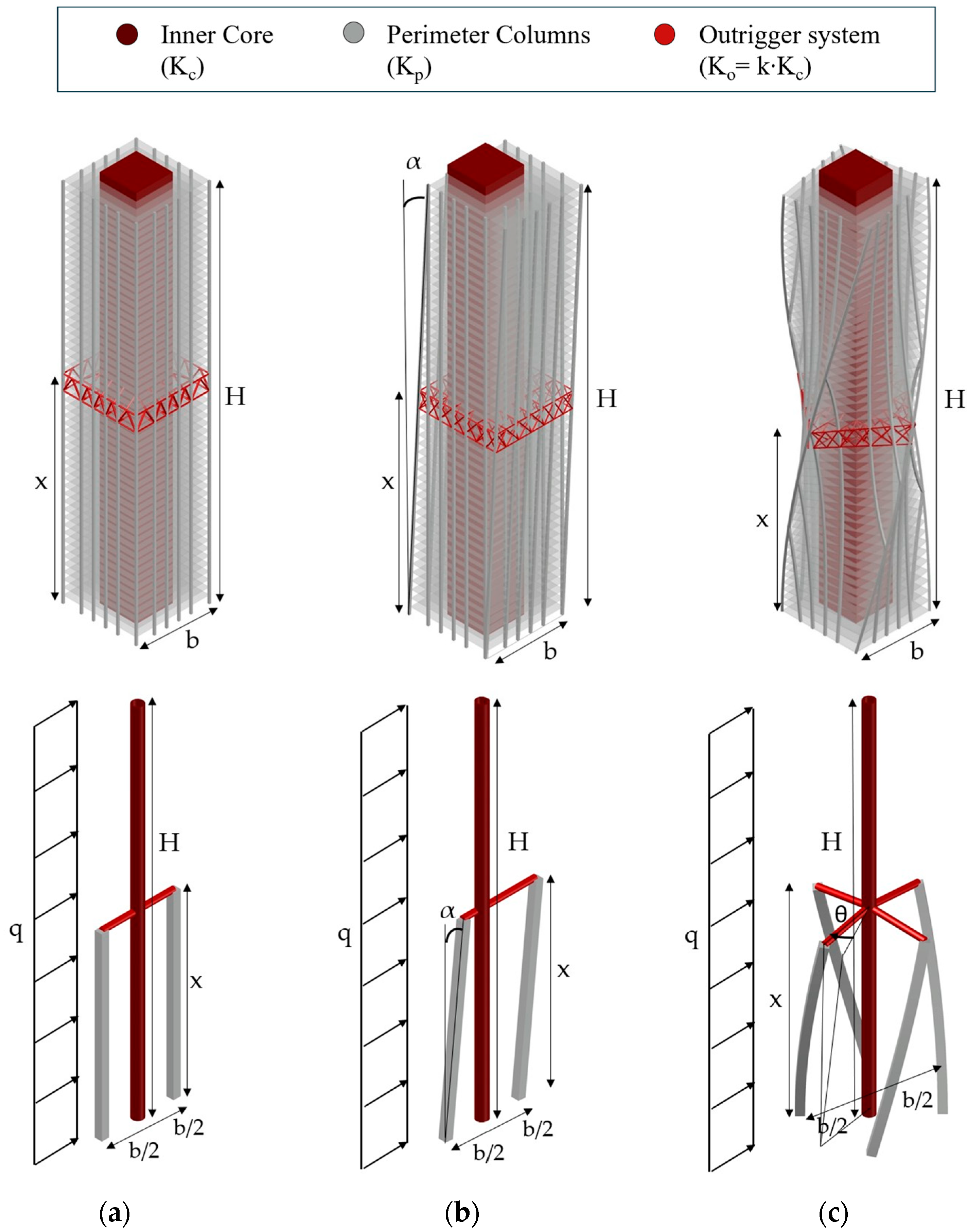
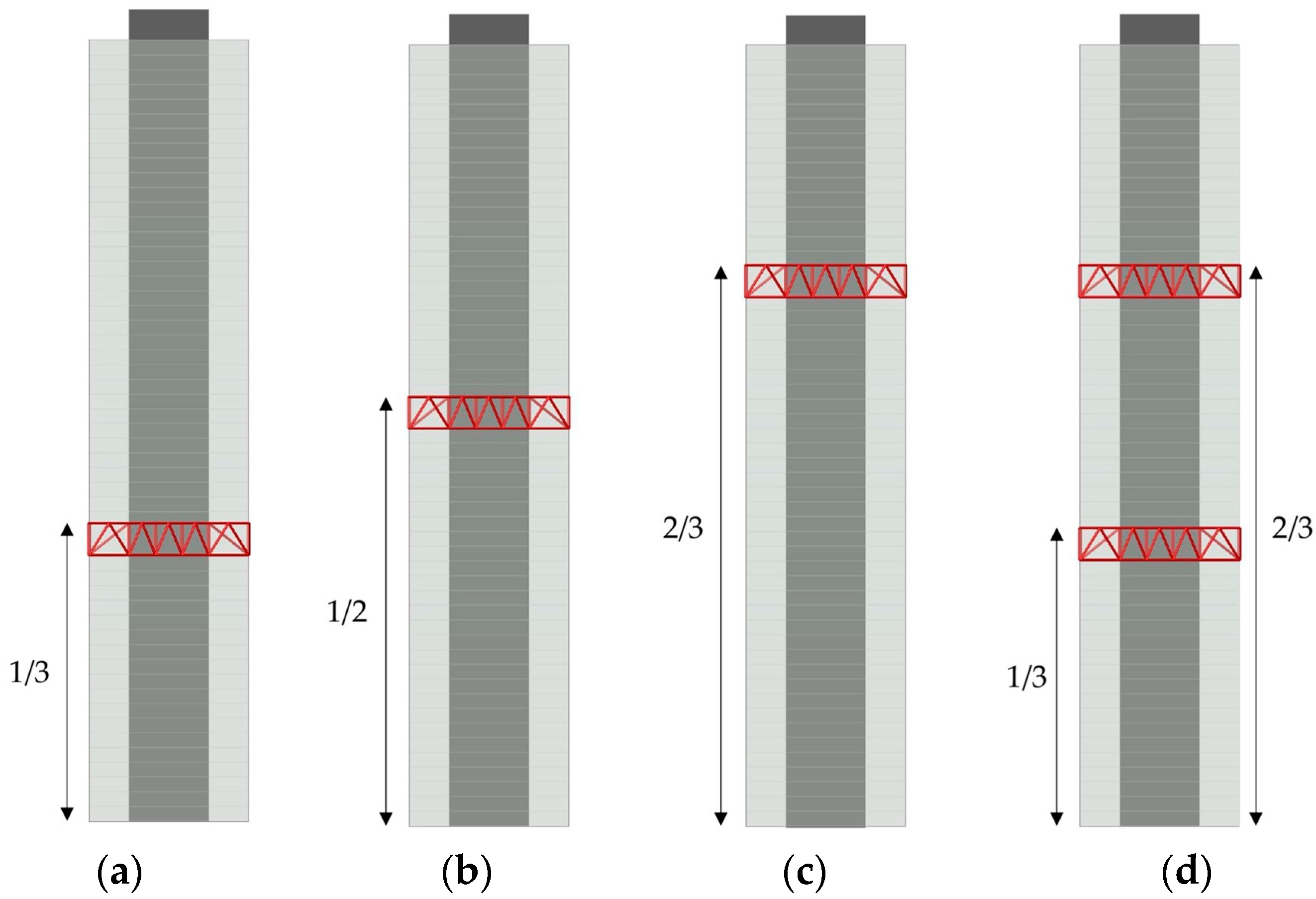
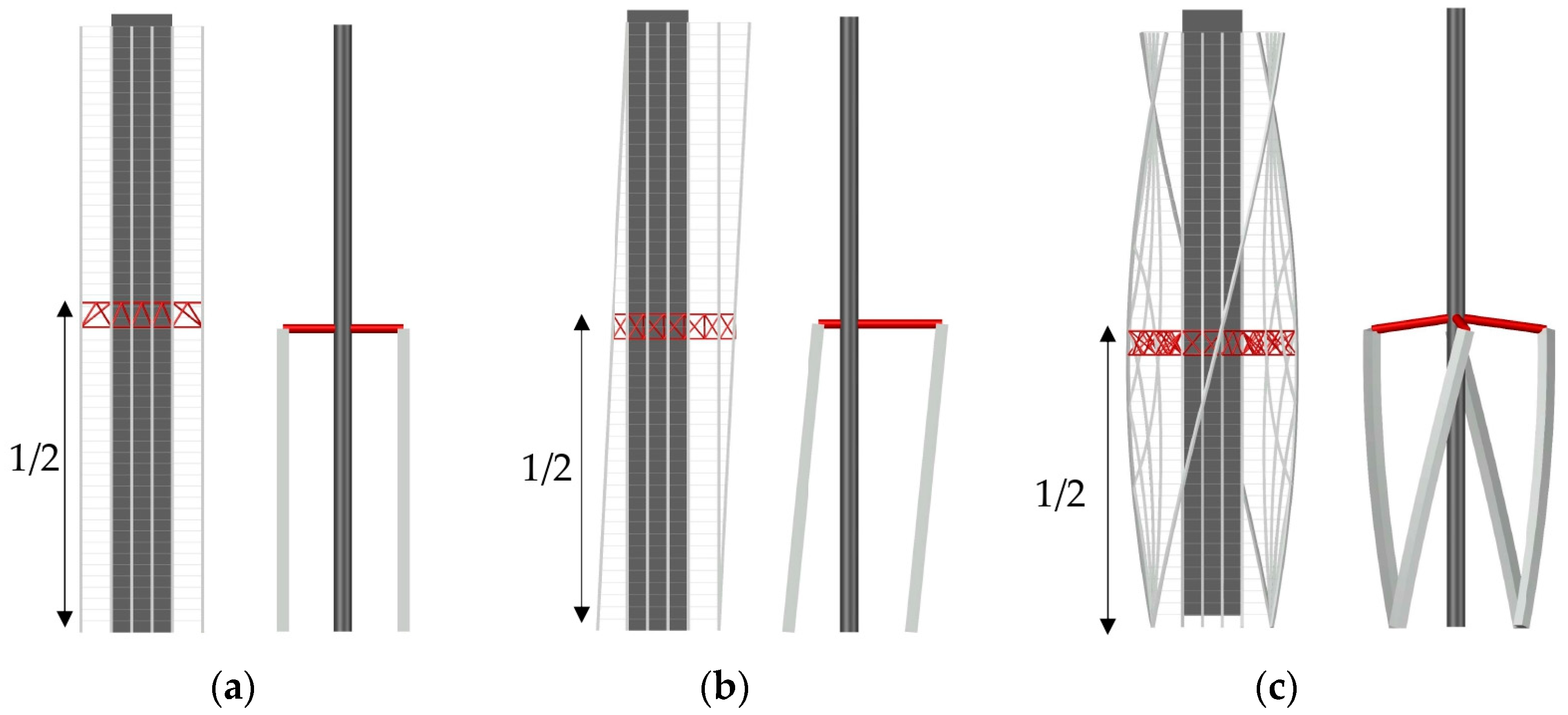
2.2. Parametrization of the Core–Column–Outrigger System

This section explores the effectiveness of outrigger systems in mitigating displacement and stress demands in complex-shaped tall buildings subjected to uniformly distributed lateral load. A parametric analysis was performed by varying the building geometric attributes, the outrigger-to-core relative stiffness, and the number and location of outriggers along the height. Given the large number of variables, simplified numerical models were preferred in lieu of computationally intensive, detailed models. The equivalent models were derived from the conceptualization of actual 3D models, as shown in Figure 2.
A 50-story reference building was considered with a 40 × 40 m square plan and a 4 m story height. The primary lateral load-resisting system comprises an RC MRF structure and a central square RC core with a 20 m side length and 1.2 m wall thickness. The core is made with C50/60 concrete. Six 1.5 × 1.5 m RC perimeter columns are positioned along each building side. The structure incorporates a secondary interior system consisting of two-story-deep outriggers. Linear elastic material behavior was assumed for all structural elements. The inner core was idealized as a vertical cantilever Euler–Bernoulli beam fixed at the base to capture its primary flexural stiffness (Figure 2). This simplification is a common approach in the preliminary design and analysis of tall buildings, effectively representing the core’s global behavior under lateral loading (e.g., [27]).
Outriggers were modeled as horizontal, perfectly rigid arms extending from the core to the perimeter columns. This idealization primarily represents their function in inducing axial forces within these columns to counteract overturning moments, thereby retaining the fundamental core-to-column load-transfer mechanism. Notwithstanding the inherent flexibility of actual outrigger members, their principal role as stiff connecting elements renders the rigid link assumption a justifiable simplification for the assessment of overall structural system behavior, particularly within the context of parametric studies where relative stiffness constitutes a key variable (e.g., [53]). It is acknowledged that these idealizations inherently exclude second-order effects and localized phenomena such as differential axial shortening between the core and perimeter columns due to elastic deformation, as well as potential shear lag in the core and flexural deformations in the outriggers. However, the scope of this simplified model is specifically intended for a preliminary parametric investigation of the outrigger effectiveness across a range of complex geometric configurations, before more detailed analyses are warranted.
Two equivalent columns represent the aggregate stiffness and load-carrying capacity of the perimeter columns. The cross-sectional properties of these equivalent columns were calibrated to ensure that the lateral stiffness of the simplified model approximated that of the detailed model. By focusing on essential structural elements and their interactions, in fact, the simplified model effectively provides valuable insights into the outrigger system’s global behavior and its influence on displacement and stress demands under lateral loading. While more complicated models, incorporating outrigger flexibility and detailed column representation, could capture local effects, this simplified approach provides a pragmatic balance between accuracy and computational efficiency, making it well suited for the parametric investigation undertaken in this study.
To avoid adding unnecessary complexity to the general problem, the core and equivalent columns were modeled with uniform cross-sections and material properties throughout their height. The simplified model was subjected to a uniformly distributed lateral load (q) of 150 kN/m applied along the full height of the core. For the tilted model, lateral forces were applied in the direction of tilt. While acknowledging the non-uniform, height-dependent nature of actual wind, this simplification facilitates generalization and interpretation of the outrigger behavior through direct inter-model comparisons. The implementation of a detailed, floor-specific wind profile, often characterized by exponential variations with height, would introduce a level of complexity incompatible with the simplified analytical framework employed herein, which lacks a discrete representation of individual floor diaphragms. Furthermore, the assumption of uniformly distributed lateral loads constitutes a recognized and established methodology in the preliminary structural analysis of tall buildings and in foundational studies concerning the behavior of their lateral load-resisting systems (e.g., [6,7,11,12,54], among many others), enabling the isolation and focused examination of key structural parameters. Although load distribution might affect optimal outrigger placement [35], research has demonstrated that uniform loading tends towards slightly higher optimal locations for outriggers, and these minor level variations minimally impact drift reduction [19,35,43,55]. Notably, Chen et al. [56] found uniform loading to yield the most conservative inter-story drift for one and two-outrigger configurations, supporting its use for a robust preliminary evaluation.
Three geometric configurations were analyzed for the reference building: a regular geometry (labeled as the R model), a tilted geometry (T model) with an angle α relative to the vertical axis, and a twisted geometry (W model) characterized by an angle θ with respect to the baseline. All simplified analytical models share the same height and square plan dimensions. As depicted in Figure 2a,b, two-dimensional simplified models adequately represented the regular and tilted configurations. However, the twisted geometry required a three-dimensional model to capture its inherent behavior (Figure 2c). In this latter case, four twisted columns, connected to the central core by four horizontal outrigger arms, were explicitly modeled.
Referring to Figure 2, the following parameters are specified. The inner core is defined by a total height (H = 200 m) and flexural stiffness (Kc), derived from its moment of inertia (Ic = 5.34 × 1011 cm4) and the concrete elastic modulus (Ec = 37.3 GPa). Each equivalent column, located at a distance b/2 (20 m) from the core centerline, exhibits a flexural stiffness calibrated to represent the contribution of the perimeter columns in each geometric configuration. Specifically, the equivalent column’s flexural stiffness is set to one-half of the aggregate flexural stiffness (Kp) of the actual perimeter columns for the regular (R) and tilted (T) models, and one-quarter for the twisted (W) model.
The vertical location of the outrigger system is defined by the variable x, which represents the distance from the building’s base. The equivalent outrigger beams have a flexural stiffness (Ko) determined as a fraction of the core’s stiffness Kc through a non-dimensional characteristic parameter (k). The parameterization directly addresses a fundamental principle in outrigger design: the system’s efficiency is critically dependent on the relative flexural stiffness of the core (e.g., [39,42]). As extensively demonstrated in the literature, in fact, the extent of drift and core moment reduction achieved by outriggers is a complex function of these relative stiffnesses and the vertical placement of the outriggers along the building’s height ([23,27], among others). To capture the sensitivity of the structural response to variations in outrigger-to-core stiffness, seven distinct cases, encompassing seven discrete values of the k parameter, were analyzed. The selection of these parameter values was informed by a comprehensive survey of the existing literature on outrigger system modeling and analysis (e.g., [54,57,58]). While acknowledging that inherent real-world complexities, such as assembly tolerances and connection stresses/deformations, are approximated within this simplified analytical framework—a common and necessary step in preliminary parametric studies to isolate key behavioral trends—the chosen range of k values aims to capture a spectrum of realistic and theoretically significant outrigger stiffness ratios encountered in practice and explored in prior research.
For regular and tilted models, this stiffness is distributed across two arms (k∙ Kc/2), whereas for twisted structures it is distributed across four arms (k∙ Kc/4). Detailed stiffness parameters for the outriggers are presented in Table 1. In the simplified models, the stiffness variation was simulated by adjusting the equivalent outrigger cross-section using S450 circular hollow tubes (Es = 210 GPa). Models without outriggers were simulated using the first cross-section typology, characterized by a near-zero k value.
The geometric attributes of the tilted and twisted configurations were parametrically varied, as illustrated in Figure 3. The tilt angle (α) ranged from 1° to 4°, a limit established to maintain the core within the building’s footprint. This corresponded to a floor-to-floor lateral shift (d) of 0.07 m (for α = 1°), 0.14 m (α = 2°), 0.21 m (α = 3°), and 0.28 m (α = 4°), yielding a total lateral offset D (i.e., the distance between the exterior façade and the core perimeter wall) of 3.5 m, 7 m, 10.5 m, and 14 m, respectively. The floor twist rate (θ) also varied from 1° to 4°, resulting in four models with global twist angles (Θ) of 50°, 100°, 150°, and 200°, respectively. The selection of the 1° to 4° range for both tilt and twist angles is intended to cover the lower spectrum of geometric deviations observed in real-world non-orthogonal high-rise buildings. Several iconic constructed examples demonstrate the application of these ranges, including the Shanghai Tower by Gensler (θ ≈ 1° twist), the Infinity Tower by SOM (θ ≈ 1.2° twist), and the conceptual Chicago Spire by Calatrava (θ ≈ 2° twist). For tilt, it is observed that some prominent examples like the Gate of Europe (α = 15°), Veer Towers (5°), and Altair Towers (13.8°) exhibit larger angles than those assumed in this study. However, this range allows for a focused parametric investigation of the early-stage effects of tilt and twist on the outrigger performance and overall building behavior as these geometric complexities are introduced. This is also supported by the work of Moon [37], who explored similar bounds for twisted and tilted structures, providing a valuable point of comparison.
For each building configuration (regular, tilted, and twisted), four outrigger locations (x) were analyzed: one-half, one-third, and two-thirds of the building height for single outriggers, and one-third and two-thirds of the height for two-outrigger systems. The analyzed locations are depicted in Figure 4. Finally, a total of 28(R) + 112(T) + 112(W) = 252 structural models were generated to systematically explore the combined influence of building geometry and outrigger placement.

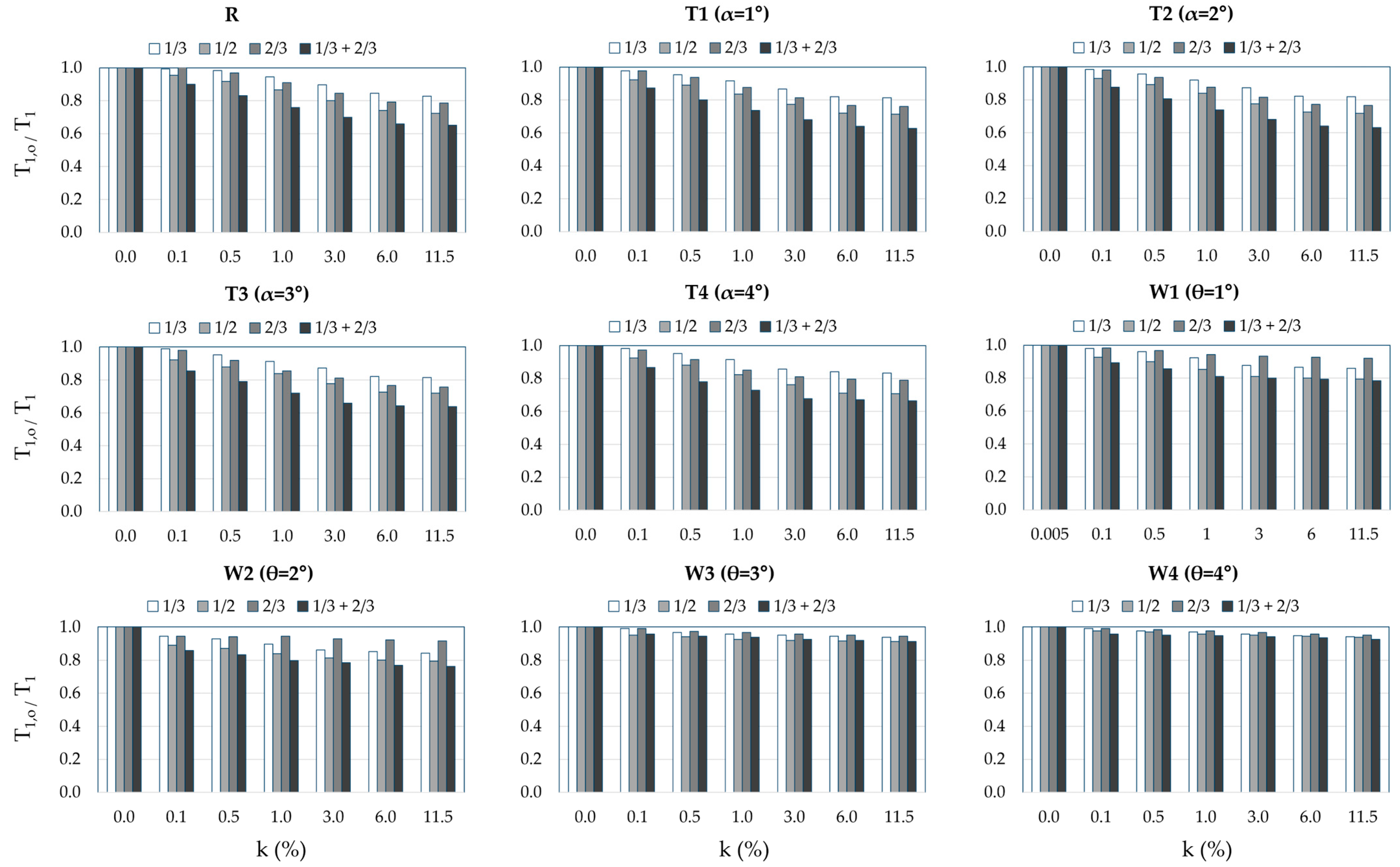
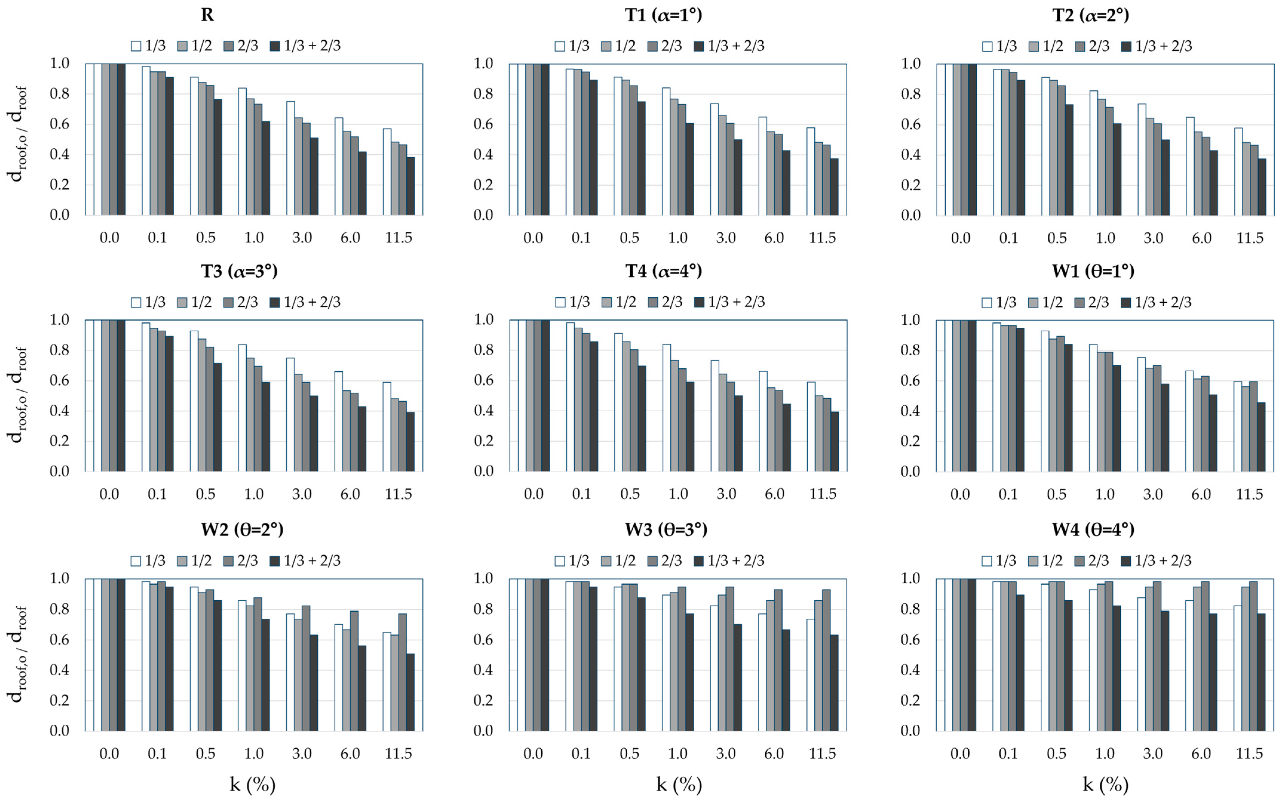
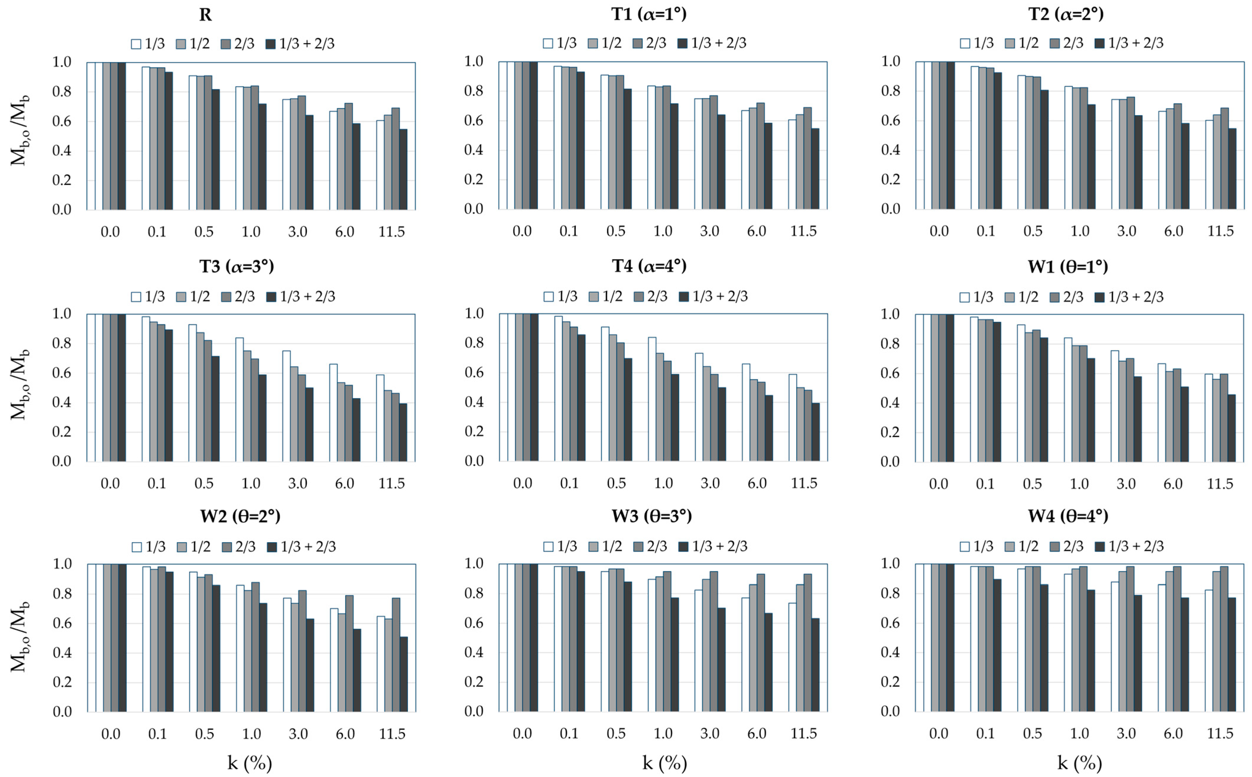
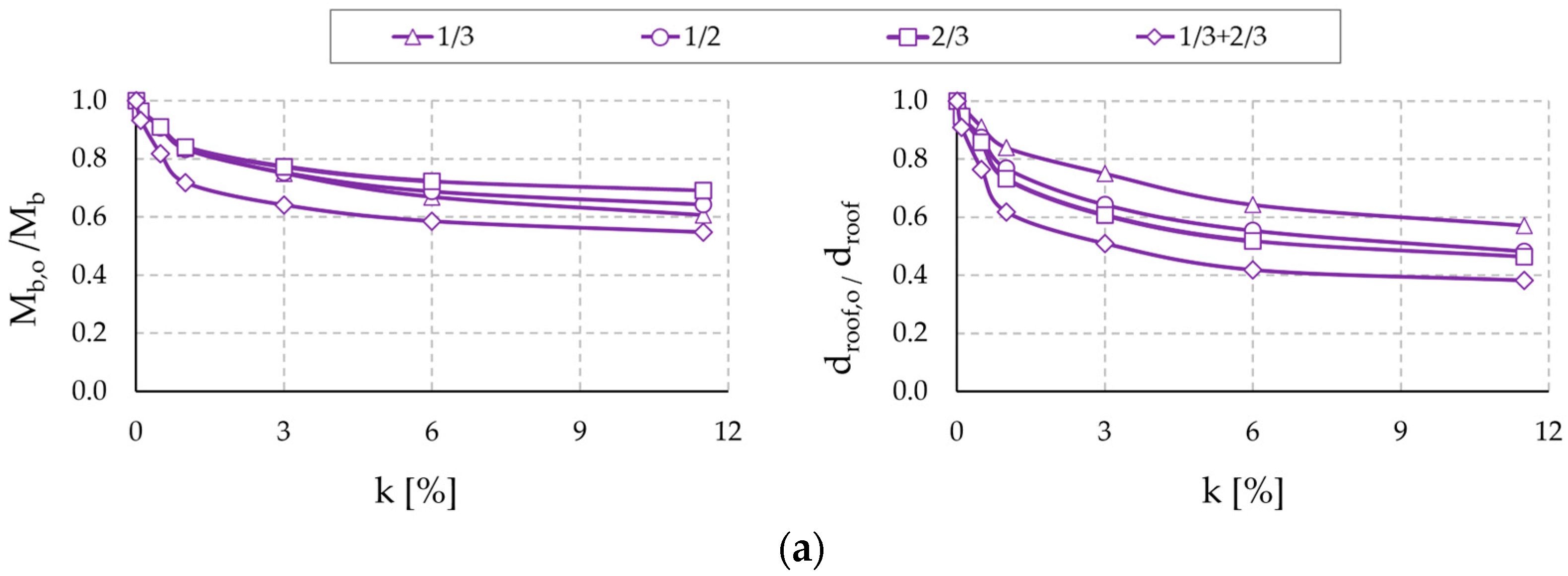
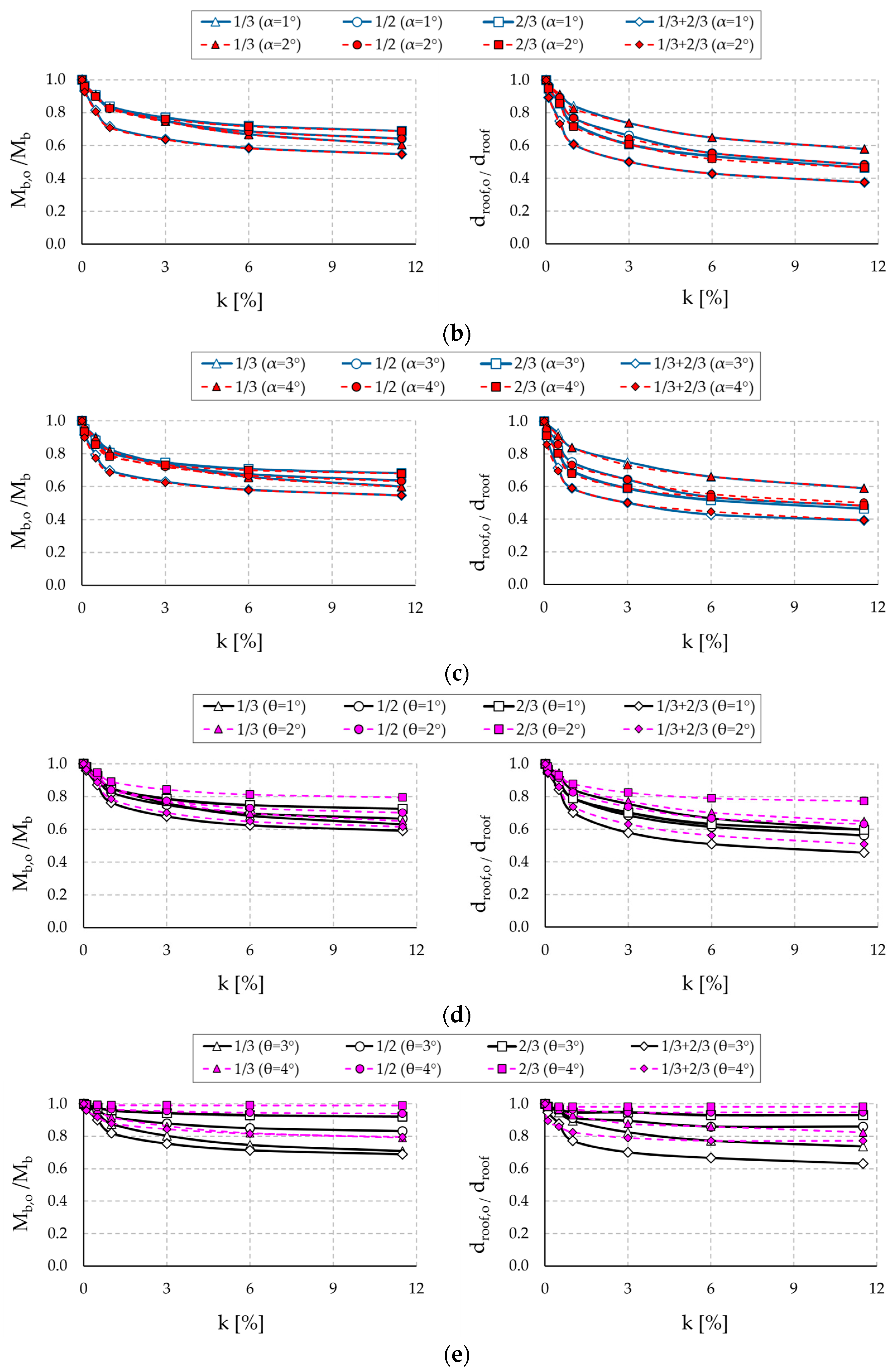
2.3. Results and Discussion

Linear static and modal analyses were performed for each simplified model. The results were compared in terms of lateral displacement, core bending moment, and fundamental period of vibration. Such Engineering Demand Parameters (EDPs) are frequently adopted to evaluate the global performance of outrigger systems, and thereby their effectiveness. The fundamental periods for each model, both with and without outriggers, are presented in Table 2, Table 3, and Table 4 for the regular, tilted, and twisted configurations, respectively. As previously stated, models without outriggers were simulated with very low flexural stiffness. Consistent with the existing literature, the results demonstrate that the addition of outriggers increases the overall lateral stiffness, which, in turn, yields a reduction in the fundamental period for all the analyzed structures. This effect is more pronounced with increasing flexural stiffness of the equivalent beams representing the outriggers.
Focusing on geometric parametrization, complex-shaped buildings without outriggers exhibit higher modal periods compared to regular buildings without outriggers. As the structural mass remains substantially constant across the three typologies, this phenomenon is attributable only to the inherent flexibility of irregular structures. This finding aligns with Mulla and Srinivas [59], who attributed this effect to discontinuities in stiffness, mass, and geometry along the building height. Notably, the introduction of outriggers generally contributes in mitigating such irregularities, especially when two outriggers are adopted (last column of the tables). For example, assuming a core-to-outrigger flexural stiffness ratio of 11.5% for the regular model results in the following reductions in fundamental periods: 17% with an outrigger at one-third of the building height, 28% at mid-height, 21% at two-thirds height, and 35% when two outriggers are considered. Similar reduction percentages are observed for the tilted model with minimal differences across the tilt angles (i.e., 18% at one-third height, 28% at one-half height, 23% at two-thirds height, and 36% at one-third and two-thirds locations).
These values progressively decrease in twisted models, where the twist angle is a determining factor. Specifically, fundamental period reductions of approximately 14% (at one-third height), 21% (at mid-height), 8% (at two-thirds height), 22% (at one-third height and two-thirds) are observed for twist angles of 1° and 2° per floor. Minimal lateral stiffness gains are reported for twist angles of 3° and 4° per floor, with reductions of approximately 6%, 6%, 5%, and 7%, respectively. Figure 5 graphically illustrates the normalized fundamental periods of the analyzed structures, expressed as a ratio of the fundamental period of the outrigger-equipped structure to that of the equivalent structure without outriggers (T1,o/T1).
Consistent trends are observed in the bending moment and lateral top displacement results. Such EDPs are widely recognized as crucial metrics for assessing outrigger system effectiveness. Bending moments at the core base inform the overall demand on the main lateral load-resisting element, and their reduction is a primary objective of outrigger systems. Lateral top displacements directly quantify the building’s deformation induced by lateral loads. Excessive sway can cause serviceability issues (e.g., occupant’s discomfort) and even instability. Thus, minimizing displacement is another essential task.
Top displacements and bending moments for each analyzed typology are illustrated in Figure 6 and Figure 7, respectively, as a function of the outrigger-to-core stiffness ratio. Core base bending moments are normalized by the corresponding value for the no-outrigger case (Mb,o/Mb) to clearly show the impact of the outrigger system on moment demand. Similarly, roof displacements are normalized (droof,o/droof). At the peak analyzed core-to-outrigger flexural stiffness ratio (11.5%), maximum reductions in roof displacements are achieved compared to the baseline non-outrigger configuration. Reduction percentages range from 40% to 60%, varying with outrigger placement along the building height. Two-outrigger configurations yield the highest reductions, while outriggers at one-third height yield the lowest, with intermediate reductions of 50% observed at mid-height and two-thirds height.
Similar results are observed for the core bending moments, with reductions slightly lower ranging from 40% (one-third height) to 45% (two-outriggers). However, the mid-height and two-thirds height locations exhibit, in general, the least favorable reductions among the analyzed configurations. Twisted structures confirm the trends, exhibiting significantly diminished gains in both displacements and core moments as the twist angle increases from θ = 1° to θ = 4°. Specifically, in this latter case, reductions are approximately 20% for both displacements and core moments at one-third height and with two outriggers. Very limited improvements are observed at mid-height (5%) and two-thirds height (1%). Overall, the presented results are in good agreement, demonstrating that enhanced lateral stiffness from outriggers translates to reduced top displacement and core bending moment demands compared to the non-outrigger condition. This effect intensifies with increasing outrigger stiffness, aligning with the fundamental period findings.
To shed some light on the distinctive profiles, a detailed analysis of the impact of the core-to-outrigger stiffness ratio on the identified EDPs is presented in Figure 8 for the examined structures. As already observed by Atkinson [51], the rate of improvement diminishes beyond a certain outrigger flexural stiffness threshold, where further increments yield only marginal performance gains. However, structural geometry also plays a critical role in this regard. In the plots for regular and tilted models, a sharp decrease in normalized bending moments and lateral displacements is shown up to a relative stiffness ratio of 3% (approximately a 25% reduction for both EDPs and all geometries). Between 3% and 6%, small improvements are observed (relative difference of approximately 10%). Beyond this threshold, the curves flatten, indicating comparable performance with increasing outrigger stiffness (approximately 5%). As previously noted, outrigger system efficacy in twisted models exhibits a strong inverse correlation with twist rate. Outrigger benefits diminish with increasing twist, and beyond a 3° twist, outrigger effectiveness is significantly reduced. Beyond a stiffness ratio of 3, relative differences range from 5% to 0%, depending on the outrigger’s location.
Based on the outcomes provided so far, two key interpretations can be drawn. First, a mid-height outrigger location provides a reasonable compromise between enhanced lateral stiffness and material consumption. In general, a two-outrigger system appears to be more effective than a single outrigger in reducing core bending moments and top displacements. However, this might be attributable to the adoption of uniform cross-sections for the equivalent outrigger beams across the model typologies, thus endowing two-outrigger configurations with inherently greater stiffness. As observed by Chambulwar et al. [60], optimal outrigger placement strongly depends on the design objective: top outriggers minimize wind-induced drift, bottom outriggers reduce overturning, and mid-height outriggers reduce bending moments. Consequently, outrigger placements at two-thirds and one-third of the building height are anticipated to maximize both displacement and core base bending moment reductions. However, for a single outrigger, the optimal location—where “optimal” denotes the configuration that minimizes material consumption while maximizing structural performance—can be reasonably identified at mid-height even for complex-shaped tall structures.
Second, outrigger systems are more effective for regular and tilted configurations than for twisted geometries, with efficacy decreasing as geometric complexity increases. Specifically, outrigger systems demonstrate comparable lateral stiffness enhancement in regular and tilted configurations. Moon [37,38] attributes the superior performance of tilted structures to a triangulation effect within the core–column–outrigger system. The tilt induces a large, complex triangular geometry, which facilitates a more efficient load-transfer mechanism. Lateral forces acting on the tilted structure try to deform this triangle but are redirected along the core, columns, and outriggers, primarily as axial forces—compression and tension—rather than bending moments arising from non-tilted structures. Increased tilt angles further optimize this triangular geometry, improving lateral load resistance. On the other hand, outrigger systems exhibit a marked reduction in effectiveness within highly twisted tall buildings, resulting in only marginal improvements to lateral stiffness. This performance degradation stems from several factors. Primarily, the inherent geometry of twisted configurations causes complex load-transfer mechanisms, disrupting the efficient force redistribution observed in regular and tilted structures. Also, the triangulation effect, which facilitates efficient load transfer in tilted structures, is not replicable within twisted configurations. Secondly, the planar operational mechanism of outriggers proves conflicting with the rotational deformation modes of twisted buildings. Indeed, these structures are susceptible to significant torsional demands under lateral loading, demands that outriggers, primarily designed to enhance flexural stiffness, are ill equipped to counteract. Lastly, the twist introduces stiffness discontinuities along the building’s vertical axis, impeding the uniform distribution of forces and thereby limiting outrigger effectiveness. The findings align with prior research [61,62,63,64,65], which established that the lateral stiffness of twisted towers is inherently reduced compared to their straight counterparts, with an inverse correlation observed between lateral stiffness and the angle of twist. Consequently, the design of highly twisted configurations necessitates the careful consideration and implementation of alternative or supplementary lateral load-resisting systems to ensure adequate structural performance.

3. Refined Modeling for Outrigger Systems

This section presents an investigation intended to examine in greater detail the structural behavior of three representative typologies selected from the dataset described in Section 2: the regular geometry (R), the 4° tilted geometry (T4), and the 2° twisted geometry (W2). Additionally, this analysis provides an opportunity to validate the demand predictions of the simplified analytical models through a comparative analysis with refined 3D frame models.

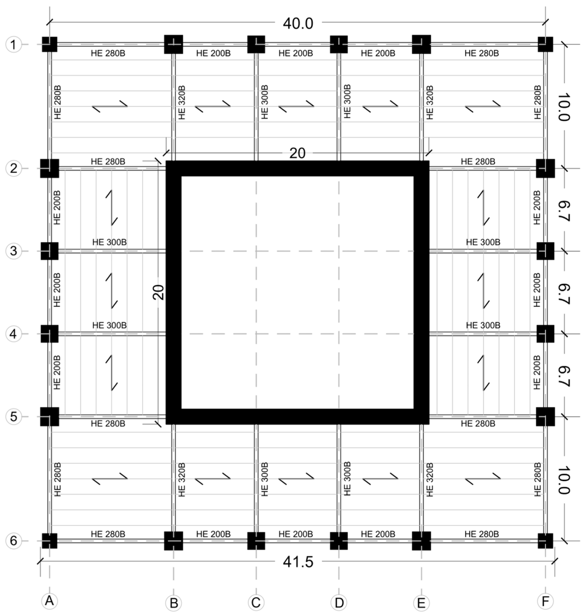
3.1. Model Description

For comparative purposes, the structural characteristics of the refined models align with those detailed in Section 3. Specifically, a 200 m tall building (50 stories) with a 40 m square plan footprint was adopted. An internal modular grid portions the plan to facilitate the positioning of the RC shear wall core and the arrangement of the perimeter columns (as illustrated in Figure 9). Key characteristics of the reference structure are summarized in Table 5.
To isolate the effects of geometric configuration, identical design attributes were adopted across all models, including member sizes for beams, columns, core, and outriggers. Each refined model incorporates a single double-story steel outrigger with a steel belt-truss, positioned at mid-height (between the 24th and 26th floors). Outrigger and belt-truss configurations were adjusted to accommodate rotational floor displacements in the twisted model and elongation/shortening of spaces near the central core due to horizontal floor translations in the tilted models.
Gravity loads comprise dead loads of 7 kN/m2 and live loads of 2 kN/m2. Composite slabs, designed for office tower applications, were dimensioned to support live loads. Steel beams were dimensioned uniformly across all three models, reflecting the consistent slab typology, with minor variations in beam length present in the tilted and twisted models. Within the scope of the present study, wind action was calculated according to the Italian technical code (NTC2018) by assuming a base speed of 40 m/s. Member cross-sections were sized to comply with code-based stiffness and strength criteria for the relevant combination of wind and gravity loads. To facilitate comparisons between refined and simplified models, column tapering was neglected, and column sizes remained constant throughout the building height. The structural properties of the refined models are shown in Table 6 and Figure 9.
In the refined models, RC columns and steel beams were modeled as frame elements. The RC core shear walls were represented using an equivalent frame approach, which employs infinitely rigid beams to simulate shear wall stiffness and connect axial centerlines. Core shear walls and columns were fixed at the base, and outriggers were rigidly connected to the core and perimeter columns. Slabs were not explicitly modeled but their influence was accounted for by applying uniform distributed loads directly to the floor beams. In the design of tall buildings, it is common practice to assume rigid floor diaphragms, whereby the mass of each floor is concentrated at its geometric center. Thus, lateral wind loads were applied at the floor center of mass. This simplification facilitates computational efficiency and is a reasonable approximation of the structural behavior.
As far as the comparative analysis between refined and simplified models is concerned, a uniformly distributed lateral wind load was assumed along the building height, calibrated to produce an equivalent base shear of 30,000 kN, consistent with the code-based provisions. This base shear corresponds to the value obtained by applying a unit load of 150 kN/m to the core in both model types. Gravity loads and load combinations were neglected within this specific comparison. Figure 10 depicts the refined models alongside their corresponding simplified counterparts.

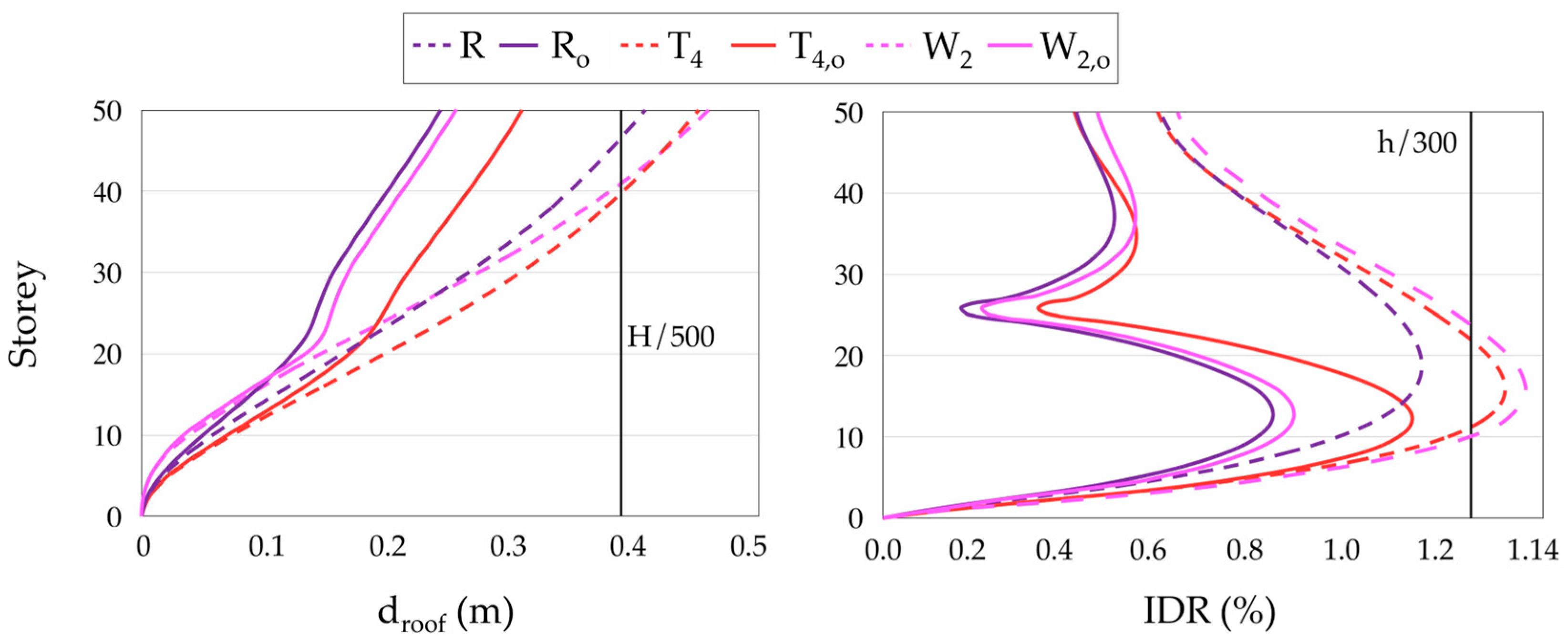
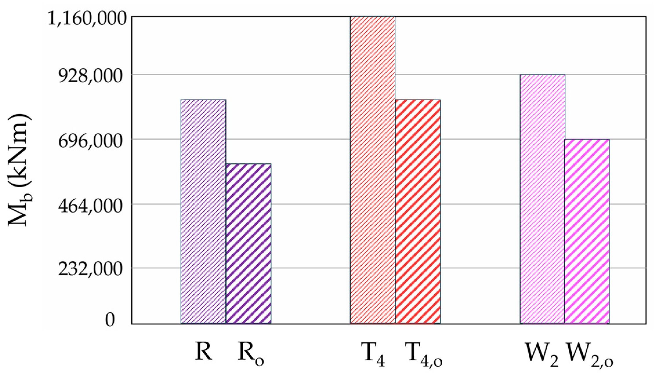
3.2. Results and Discussion

An investigation into the behavior of the refined structures, with and without outriggers, is initially performed. A subscript “o” is appended to denote the outrigger condition in the results (i.e., Ro for the regular building, T4o for the tilted building, and W2o for the twisted building). Natural periods and modal participating mass ratios of the first twelve vibration modes are detailed in Table 7, Table 8 and Table 9 for the three refined models. Notably, irregular structures require a greater number of modes to achieve 85% mass participation, reflecting a more complex dynamic behavior compared to the regular structure. It is crucial to recognize that a direct comparison of the first mode natural periods between the simplified (Table 2, Table 3 and Table 4) and refined models (Table 7, Table 8 and Table 9) is inappropriate due to their inherent differences in structural mass. Specifically, the refined models incorporate mass derived from floor framing, slabs, and gravity loads to enable a complete assessment of their dynamic characteristics.
The introduction of outriggers consistently reduces natural periods, indicating an increase in structural stiffness. Such a stiffening effect is crucial for maintaining the top and inter-story drifts within acceptable limits, ensuring serviceability and preventing structural damage under wind loads.
For wind-induced lateral displacement control, the maximum allowable top drift is set to H/500, and the maximum allowable inter-story drift is set to h/300, where H and h denote the total building height and the inter-story height, respectively. Figure 11 presents a comparative analysis of outrigger efficacy in controlling the top displacements (droof) and inter-story drifts (IDR) within the refined models, showcasing configurations with and without outrigger systems. Figure 12 presents the same comparison for core base bending moments. The refined model without outriggers exhibits a maximum lateral deflection at the top story and an IDR exceeding the maximum allowable lateral top displacement of 0.4 m and the allowable inter-story drift of 1.3%, respectively. The inclusion of an outrigger with a belt-truss demonstrably reduces both maximum wind-induced lateral deflection at the top story and inter-story drift values in all other outrigger-equipped models. Importantly, these EDPs now fall within the design-acceptable thresholds, confirming the outrigger’s effectiveness in mitigating lateral displacement demands under wind load. Displacement reductions are observed in both regular and irregular building geometries at the outrigger level. The initial story displacements remain largely the same, while a substantial reduction occurs from mid-height, where the outrigger system is installed. IDR values follow the same trend. Such findings are consistent with the relevant literature (e.g., [43,46,66]). In line with Moon’s [33] observations, curvature reversals occur proximate to outrigger truss levels (24th–26th floors) in straight, tilted, and twisted configurations. The outrigger system demonstrates consistent efficacy across minor geometric variations. A substantial reduction is also observed in the core base bending moments upon outrigger system implementation.
Lastly, a comparative analysis of refined and simplified models, with and without outriggers, evaluates the approximation method’s accuracy and highlights similarities and differences. The comparison is performed in terms of relevant engineering parameters, including lateral top displacement and core base bending moment. To quantify the performance enhancement provided by outriggers, an outrigger efficiency ratio is defined as the percentage reduction in each EDP achieved by the outrigger implementation. Results for both refined and simplified models, organized by building typology, are summarized in Table 10.
The comparative analysis confirms the trends and percentage performance improvements observed in Section 2. However, refined models consistently exhibit higher efficiency ratios, although differences remain within 5%, likely due to a more detailed modeling of the outrigger system and its connections to the MRF. This refinement, in fact, allows for a more accurate capture of the intricate structural interaction between the braced outrigger system and the belt-truss assembly, as well as load-transfer mechanisms and component stiffness contributions. Conversely, simplified models, designed for broad parametric studies, inherently approximate these complex interactions since only the contribution of outriggers was modeled for practical reasons.
A pronounced improvement is generally observed in lateral displacement compared to the reduction in the core base bending moment, a result consistent with observations made on simplified models. Notably, the refined twisted model (W) shows a significant overall improvement. This can be associated with a more accurate representation of the belt-truss effect, which contributes significantly to the torsional stiffness of the structure, whereas outriggers are effective in increasing lateral stiffness. The results are also well aligned with previous studies by Dedeoğlu and Calayir [66], which demonstrated that outrigger and belt-truss systems in shear-wall framed structures produce a combined increase in lateral and torsional stiffness. This latter contribution is paramount in complex structural forms like twisted buildings, where torsional stiffness plays a fundamental role in resisting rotational deformation demands induced by lateral loads. In the simplified models, where the torsional stiffening effect imparted by the belt-trusses is not explicitly modeled, the overall effectiveness of the outrigger system in mitigating torsional response may be underestimated.
In conclusion, the findings demonstrate that simplified models can predict the global structural behavior of regular or moderately irregular structures with reasonable approximation. However, it is crucial to contextualize the application of such simplified models to the preliminary design stage and for comparative purposes only. Their inherent limitations, in fact, preclude the accurate representation of crucial tall building characteristics, including the discrete distribution of mass, the application of realistic gravity loading, and the attenuated stiffness contribution of the belt-truss system. Furthermore, this level of idealization inherently prevents the direct verification of a critical EDP for structural damage assessment, namely the inter-story drift profile. Refinement of the modeling assumptions is essential for the accurate analysis of complex geometries like highly twisted buildings, where accurately capturing torsional response and the complete lateral system interaction is fundamental for reliable structural performance assessment and design.

4. Conclusions

This study provides a systematic investigation into the effectiveness of outrigger systems for enhancing the structural performance of tall buildings with both conventional and complex geometries. The findings clearly demonstrated the significant improvement in lateral stiffness achieved through outrigger implementation, evidenced by substantial reductions in fundamental periods, lateral displacements, and core base bending moments under wind-induced loads.
The effectiveness of these systems was found to be highly dependent on the critical interplay between the building configuration, outrigger location, and relative flexural stiffness. While regular and tilted geometries showed significant performance gains with increasing outrigger-to-core stiffness ratios (up to 3%), twisted geometries experienced diminishing returns and reduced overall effectiveness beyond a 2° twist per floor. Notably, the benefits of increased outrigger stiffness plateaued beyond a ratio of 6%. Moreover, the results confirm that optimal outrigger placement is contingent on the specific design objective, with mid-height locations often providing a good compromise.
Finally, the comparative analysis between the simplified and refined models underscored the importance of accurate belt-truss modeling. Refined models exhibited higher outrigger efficiency ratios, reflecting a more accurate representation of the overall structural behavior, especially regarding torsional stiffness. In general, the results confirmed the efficacy of outrigger systems for regular and moderately irregular buildings. However, the study also revealed that the inherent challenges of highly twisted geometries necessitate careful consideration of alternative or supplementary lateral load-resisting systems to ensure adequate structural performance. While this preliminary research provides a comprehensive parametric analysis of outrigger systems in tall buildings with varying geometric shapes under static wind loading, it is important to acknowledge certain inherent limitations. Firstly, the study primarily utilized simplified and linear elastic models to establish fundamental behavioral trends. Future investigations could explore the influence of non-linear material behavior and geometric non-linearities under extreme lateral loads. Secondly, while the impact of building geometry and outrigger configuration was extensively investigated within this initial scope, other relevant design factors such as core typology, variations in building height, and tapering of the core and column sections were not considered and warrant future research. Finally, the present parametric study aimed to establish the fundamental behavioral trends of outrigger systems using a simplified, uniformly distributed lateral load. Therefore, a formal sensitivity analysis examining the effects of non-uniform wind and seismic load distributions was not included within the scope of this initial investigation. Future work should address this limitation by exploring the response of outrigger systems under more complex and realistic loading conditions.

Author Contributions

Conceptualization, G.A. and E.C.; methodology, G.A. and F.M.; software, E.C.; validation, G.A. and F.M.; formal analysis, G.A.; investigation, G.A. and E.C.; resources, F.M.; data curation, E.C.; writing—original draft preparation, G.A. and E.C.; writing—review and editing, G.A. and F.M.; visualization, G.A. and E.C.; supervision, G.A. and F.M.; project administration, F.M.; funding acquisition, F.M. All authors have read and agreed to the published version of the manuscript.

Funding

Giulia Angelucci and Fabrizio Mollaioli gratefully acknowledge the PNRR (Piano Nazionale di Ripresa e Resilienza) funding scheme as part of the National Research Centre CN1 on “High-Performance Computing, Big Data and Quan-tum Computing”—Spoke 5—“Environment and Natural Disaster: Framework and methodologies for impact evaluation and risk mitigation”, Research Project No.CN1221844D08208F (Directorial Decretation no. 1031 of 17 June 2022).

Institutional Review Board Statement

Not applicable.

Informed Consent Statement

Not applicable.

Data Availability Statement

The original contributions presented in this study are included in the article. Further inquiries can be directed to the corresponding author.

Conflicts of Interest

The authors declare that there are no known conflicts of interest associated with this publication.

References

  1. Kavyashree, B.G.; Patil, S.; Rao, V.S. Evolution of Outrigger Structural System: A State-of-the-Art Review. Arab. J. Sci. Eng. 2021, 46, 10313–10331. [Google Scholar] [CrossRef]
  2. Angelucci, G.; Mollaioli, F.; Molle, M.; Paris, S. Performance assessment of timber high-rise buildings: Structural and technological considerations. Open Constr. Build. Technol. J. 2022, 16, 1–12. [Google Scholar] [CrossRef]
  3. Gore, N.G.; Mhatre, P. Outrigger Structural System—A Review and Comparison of the Structural System. Int. J. Eng. Trends Technol. 2018, 64, 31–35. [Google Scholar] [CrossRef]
  4. Zhou, K.; Luo, X.W.; Li, Q.S. Decision framework for optimal installation of outriggers in tall buildings. Autom. Constr. 2018, 93, 200–2013. [Google Scholar] [CrossRef]
  5. Sasikumar, S.; Jithma, T. Analytical Study of Tall Building with Outrigger System. Int. Res. J. Eng. Technol. 2020, 7, 3420–3423. [Google Scholar]
  6. Moon, K.S.; Connor, J.J.; Fernandez, J.E. Diagrid structural systems for tall buildings: Characteristics and methodology for preliminary design. Struct. Des. Tall Spec. Build. 2007, 16, 205–230. [Google Scholar] [CrossRef]
  7. Montuori, G.M.; Mele, E.; Brandonisio, G.; De Luca, A. Geometrical patterns for diagrid buildings: Exploring alternative design strategies from the structural point of view. Eng. Struct. 2014, 71, 112–127. [Google Scholar] [CrossRef]
  8. Angelucci, G.; Mollaioli, F. Voronoi-Like Grid Systems for Tall Buildings. Front. Built Environ. 2018, 4, 78. [Google Scholar] [CrossRef]
  9. Scaramozzino, D.; Lacidogna, G.; Carpinteri, A. New Trends Towards Enhanced Structural Efficiency and Aesthetic Potential in Tall Buildings: The Case of Diagrids. Appl. Sci. 2020, 10, 3917. [Google Scholar] [CrossRef]
  10. Angelucci, G.; Mollaioli, F.; Tardocchi, R. A new modular structural system for tall buildings based on tetrahedral configuration. Buildings 2020, 10, 240. [Google Scholar] [CrossRef]
  11. Stromberg, L.L.; Beghini, A.; Baker, W.F.; Paulino, G.H. Topology optimization for braced frames: Combining continuum and beam/column elements. Eng. Struct. 2012, 37, 106–124. [Google Scholar] [CrossRef]
  12. Angelucci, G.; Quaranta, G.; Mollaioli, F. Topology optimization of multi-story buildings under fully non-stationary stochastic seismic ground motion. Struct. Multidiscip. Optim. 2022, 65, 217. [Google Scholar] [CrossRef]
  13. Ali, M.M.; Moon, K.S. Advances in structural systems for tall buildings: Emerging developments for contemporary urban giants. Building 2018, 8, 104. [Google Scholar] [CrossRef]
  14. Nanduri, P.M.B.R.K.; Suresh, B.; Hussain, I. Optimum Position of Outrigger System for High-Rise Reinforced Concrete Buildings Under Wind And Earthquake Loadings. Am. J. Eng. Res. 2013, 2, 76–89. [Google Scholar]
  15. Ali, M.; Moon, K.S. Structural Developments in Tall Buildings: Current Trends and Future Prospects. Archit. Sci. Rev. 2007, 50, 205–223. [Google Scholar] [CrossRef]
  16. Lame, A. Optimization of Outrigger Structures. Ph.D. Thesis, Massachusetts Institute of Technology, Cambridge, MA, USA, 2008. [Google Scholar]
  17. Kim, H.S. Optimum Locations of Outriggers in a Concrete Tall Building to Reduce Differential Axial Shortening. Int. J. Concr. Struct. Mater. 2018, 12, 77. [Google Scholar] [CrossRef]
  18. Khanorkar, A.; Sukhdeve, S.; Denge, S.V.; Raut, S.P. Outrigger and Belt Truss System for Tall Building to Control Deflection: A Review. Glob. Res. Dev. J. Eng. 2016, 1, 6–15. [Google Scholar]
  19. Chang, H.C.; Kuang, J.S. Stiffened Coupled Shear Walls. J. Eng. Mech. 1989, 115, 247–267. [Google Scholar]
  20. Chang, H.C.; Kuang, J.S. Elastic Design Charts for Stiffened Coupled Shear Walls. J. Struct. Eng. 1989, 115, 689–703. [Google Scholar]
  21. Taranath, B.S. Structural Analysis and Design of Tall Buildings, 2nd ed.; McGraw-Hill: New York, NY, USA, 1988; p. 672. [Google Scholar] [CrossRef]
  22. Taranath, B.S. Steel, Concrete, and Composite Design of Tall Buildings, 2nd ed.; McGraw-Hill: New York, NY, USA, 1997; p. 1024. [Google Scholar]
  23. McNabb, J.W. Drift Reduction Factors for Belted High-Rise Structures. Struct. Eng. 1975, 12, 88–91. [Google Scholar] [CrossRef]
  24. Herath, N.; Haritos, N.; Ngo, T.; Mendis, P. Behavior of Outrigger Beams in High Rise Buildings under Earthquake Loads. In Proceedings of the Australian Earthquake Engineering Society Conference, 18th Australian Earthquake Engineering Conference, Newcastle, Australia, 11–13 December 2009. [Google Scholar]
  25. Gerasimidis, S.; Efthymiou, E.; Baniotopoulos, C.C. Optimum outrigger location of high-rise steel buildings for wind loading. In Proceedings of the 5th European & African Conference on Wind Engineering, Florence, Italy, 19–23 July 2009. [Google Scholar]
  26. Chung, Y.K. Optimization of Outrigger Locations in Tall Buildings Subjected to Wind Loads. Ph.D. Thesis, University of Melbourne, Melbourne, Australia, 2010. [Google Scholar]
  27. Stafford Smith, B.; Coull, A. Tall Buildings Structures: Analysis and Design, 1st ed.; John Wiley & Sons Inc: New York, NY, USA, 1991; p. 552. [Google Scholar]
  28. Boggs, P.C.; Gasparini, D.A. Lateral Stiffness of Core and Outrigger System. Struct. Eng. 1983, 20, 172–180. [Google Scholar] [CrossRef]
  29. Baygi, S.; Khazaee, A. The Optimal Number of Outriggers in a Structure Under Different Lateral Loadings. J. Inst. Eng. 2019, 100, 753–761. [Google Scholar] [CrossRef]
  30. Desai, R.; Arekar, V.; Patel, V.B. Analysis of outrigger numbers and locations with different bracing system. J. Emerg. Technol. Innov. Res. 2019, 6, 444–452. [Google Scholar]
  31. Fawzia, S.; Fatima, T. Optimum position of steel outrigger system for high-rise composite buildings subjected to wind loads. Adv. Steel Constr. 2015, 2, 134–153. [Google Scholar]
  32. Kim, H.S.; Lee, H.L.; Lim, Y.J. Multi-objective optimization of dual-purpose outriggers in tall buildings to reduce lateral displacement and differential axial shortening. Eng. Struct. 2019, 189, 296–308. [Google Scholar] [CrossRef]
  33. Lee, S.; Tovar, A. Outrigger placement in tall buildings using topology optimization. Eng. Struct. 2014, 74, 122–129. [Google Scholar] [CrossRef]
  34. Chen, Y.; Zhang, Z. Analysis of outrigger numbers and locations in outrigger braced structures using a multiobjective genetic algorithm. Struct. Des. Tall Spec. Build. 2018, 27, e1408. [Google Scholar] [CrossRef]
  35. Wu, J.R.; Li, Q.S. Structural performance of multi-outrigger braced tall buildings. Struct. Des. Tall Spec. Build. 2003, 12, 155–176. [Google Scholar] [CrossRef]
  36. Alhaddad, W.; Halabi, Y.; Xu, H.; Lei, H. Outrigger and Belt-Truss System Design for High-Rise Buildings: A Comprehensive Review Part II—Guideline for Optimum Topology and Size Design. Adv. Civ. Eng. 2020, 2020, 2589735. [Google Scholar] [CrossRef]
  37. Moon, K.S. Outrigger Systems for Structural Design of Complex-Shaped Tall Buildings. Int. J. High-Rise Build. 2016, 5, 13–20. [Google Scholar] [CrossRef]
  38. Moon, K.S. Comparative Evaluation of Structural Systems for Tilted Tall Buildings. Int. J. High-Rise Build. 2014, 3, 89–98. [Google Scholar]
  39. Taranath, B.S. Optimum Belt Truss Location for High-Rise Structures. Eng. J. 1974, 11, 18–21. [Google Scholar] [CrossRef]
  40. Stafford Smith, B.; Nwaka, I.O. Behavior of Multi-Outrigger Braced Tall Building Structures. Am. Concr. Inst. 1980, 63, 515–542. [Google Scholar]
  41. Stafford Smith, B.; Salim, I. Parameter Study of Outrigger-Braced Tall Building Structures. J. Struct. Div. 1981, 107, 2001–2014. [Google Scholar] [CrossRef]
  42. Hoenderkamp, J.C.D.; Bakker, M.C.M. Analysis of high-rise braced frames with outriggers. Struct. Des. Tall Spec. Build. 2003, 12, 335–350. [Google Scholar] [CrossRef]
  43. Hoenderkamp, J.C.D. Second outrigger at optimum location on high-rise shear wall. Struct. Des. Tall Spec. Build. 2008, 17, 619–634. [Google Scholar] [CrossRef]
  44. Lee, J.; Kim, H. Simplified Analytical Model for Outrigger-Braced Structures Considering Transverse Shear Deformation. In Proceedings of the Seoul Conference, Seoul, Republic of Korea, 2–3 December 2004. [Google Scholar]
  45. Lee, J.; Bang, M.; Kim, J.Y. An analytical model for high-rise wall structures with outrigger. Struct. Des. Tall Spec. Build. 2008, 16, 839–851. [Google Scholar] [CrossRef]
  46. Lee, J.; Park, D.; Lee, K.; Ahn, N. Geometric nonlinear analysis of tall building structures with outriggers. Struct. Des. Tall Spec. Build. 2013, 22, 454–470. [Google Scholar] [CrossRef]
  47. Zhang, J.; Zhang, Z.X.; Zhao, W.G.; Zhu, H.P.; Zhou, C.S. Safety analysis of optimal outriggers location in high-rise building structures. J. Zhejiang Univ. 2007, 8, 264–269. [Google Scholar] [CrossRef]
  48. Su, R.K.L.; Wong, P.C.W.; Chandler, A.M. Application of Strut-and-tie method on outrigger braced core wall buildings. In Tall Buildings: From Engineering to Sustainability; World Scientific: Singapore, 2005; pp. 80–85. [Google Scholar] [CrossRef]
  49. Rahgozar, R.; Sharifi, Y. An approximate analysis of combined system of framed tube, shear core and belt truss in high-rise buildings. Struct. Des. Tall Spec. Build. 2009, 18, 607–624. [Google Scholar] [CrossRef]
  50. Malekinejad, M.; Rahgozar, R. Free vibration analysis of tall buildings with outrigger-belt truss system. Earthq. Struct. 2011, 2, 89–107. [Google Scholar] [CrossRef]
  51. Atkinson, J.C.H. Seismic Design of Outrigger System for Tall Buildings. Ph.D. Thesis, University of British Columbia, Vancouver, BC, Canada, 2016. [Google Scholar]
  52. Marabi, B.; Alih, S.C.; Feridmehr, I. Evaluation of the Efficiency of Single-Outrigger Structural Systems in Tall Buildings. In Proceedings of the National Conference on Wind & Earthquake Engineering, Putrajaya, Malaysia, 16–17 October 2020. [Google Scholar] [CrossRef]
  53. Taranath, B.S. Wind and Earthquake Resistance Buildings: Structural Analysis and Design, 1st ed.; CRC Press LLC: New York, NY, USA, 2004; p. 912. [Google Scholar]
  54. Patel, J.C. Study of Outrigger Structural System for High Rise Building. Ph.D. Thesis, Nirma University Institute of Technology, Ahmedabad, India, 2010. [Google Scholar]
  55. Chang, K.L.; Chen, C.C. Outrigger system study for tall building structure with central core and square floor plate. In Proceedings of the CTBUH 8th World Congress, CTBUH 8th World Congress, Dubai, United Arab Emirates, 3–5 March 2008. [Google Scholar]
  56. Chen, Y.; Cai, K.; Wang, X. Parameter study of framed-tube structures with outriggers using genetic algorithm. Struct. Des. Tall Spec. Build. 2018, 27, e1499. [Google Scholar] [CrossRef]
  57. Nissanka, N.A.C.C.; Fernando, A.M.; Gamage, J.C.P.H. Effectiveness of Various Outrigger Systems of Different Structural Materials for Lateral Load Resistance in Reinforced Concrete High-Rise Buildings. In Proceedings of the 13th International Conference on Sustainable Built Environment, Yogyakarta, Indonesia, 15–16 November 2022. [Google Scholar]
  58. Sakr, T.A.; Hanaa, E.M. Elasto-Plastic Behavior of Outrigger Braced Walls. J. Am. Sci. 2012, 8, 1230–1238. [Google Scholar]
  59. Mulla, K.A.; Srinivas, B.N. A Study on Outrigger System in a Tall R.C Structure with Steel Bracing. Int. J. Eng. Res. Technol. 2015, 4, 551–557. [Google Scholar]
  60. Chambulwar, S.; Kadam, T.S.; Bhujbal, A.M.; Konde, P.P.; Alandkar, S.B. Comparative Study of RCCC Structure with and without Outrigger System. Int. J. Res. Eng. Sci. 2021, 9, 45–47. [Google Scholar]
  61. Marmar, A.; Zouia, S.; Ismail, S.; Hallik, A. Twisted Buildings: Concepts and approaches. Archit. Plan. J. 2021, 27, 1–20. [Google Scholar] [CrossRef]
  62. Sev, A.; Başarır, B. A recent trend in tall building design: Twisted forms. Now World Sci. Acad. 2011, 6, 1603–1619. [Google Scholar]
  63. Golasz-Szolomicka, H.; Szolomicki, J. Architectural and Structural Analysis of Selected Twisted Tall Buildings. In Proceedings of the 4th World Multidisciplinary Civil Engineering, Architecture, Urban Planning Symposium, Prague, Czech Republic, 18–22 June 2018. [Google Scholar] [CrossRef]
  64. Lee, D.H.; Kim, E.S.; Kang, D.E.; Kim, T. Seismic Performance Evaluation of Twisted Outrigger System. In Proceedings of the 15th National Conference on Wind & Earthquake Engineering, Lisboa, Portugal, 24–28 September 2012. [Google Scholar]
  65. Moon, K.S. Studies on various structural system design options for twisted tall buildings and their performances. Struct. Des. Tall Spec. Build. 2019, 23, 319–333. [Google Scholar] [CrossRef]
  66. Dedeoğlu, I.O.; Calayir, Y. Effectiveness of outrigger and belt truss systems on the seismic behavior of high-rise buildings. J. Struct. Eng. Appl. Mech. 2020, 3, 180–203. [Google Scholar] [CrossRef]
Figure 1. Schematic of multi-level outrigger and belt-truss system.
Applsci 15 05643 g001
Figure 2. Conceptualization of the high-rise buildings under examination. Refined models (top row) and simplified models (bottom row) for regular (a), tilted (b), and twisted (c) geometries.
Applsci 15 05643 g002
Figure 3. Geometric parameter variations considered in this study.
Applsci 15 05643 g003
Figure 4. Outrigger locations considered: x = 1/3 (a), x = 1/2 (b), x = 2/3 (c), x = 1/3 and x = 2/3 (d).
Applsci 15 05643 g004
Figure 5. Normalized fundamental periods for the analyzed structures.
Applsci 15 05643 g005
Figure 6. Normalized roof displacements for the analyzed structures.
Applsci 15 05643 g006
Figure 7. Normalized bending moments for the analyzed structures.
Applsci 15 05643 g007
Figure 8. Normalized bending moments and roof displacements for regular model (a), tilted models with α = 1° and α = 2° per floor (b), tilted models with α = 3° and α = 4° per floor (c), twisted models with angle θ = 1° and θ = 2° per floor (d), and twisted models with θ = 3° and θ = 4° per floor (e).
Applsci 15 05643 g008aApplsci 15 05643 g008b
Figure 9. Typical floor plan.
Applsci 15 05643 g009
Figure 10. Refined and simplified analytical models for the regular structure (a), tilted structure with tilt angle of 4° per floor (b), and twisted structure with twist angle of 2° per floor (c).
Applsci 15 05643 g010
Figure 11. Wind-induced top displacement (droof) (on the left) and inter-story drift IDR (on the right), comparisons for refined building models with and without outriggers.
Applsci 15 05643 g011
Figure 12. Wind-induced core base bending moment comparisons for refined building models with and without outriggers.
Applsci 15 05643 g012
Table 1. Stiffness parameters of equivalent beams for outriggers.
kIoIR,TIW
(%)(cm4)(cm4)(cm4)
0.0054.74 × 1062.37 × 1061.19 × 106
0.19.48 × 1074.74 × 1072.37 × 107
0.54.74 × 1082.37 × 1081.19 × 108
1.09.48 × 1084.74 × 1082.37 × 108
3.02.84 × 1091.42 × 1097.11 × 108
6.05.69 × 1092.84 × 1091.42 × 109
11.51.09 × 10105.45 × 1092.73 × 109
k: ratio of the steel outrigger’s flexural stiffness to the RC core’s flexural stiffness; Io: moment of inertia of the outrigger system; IR,T: moment of inertia of a single arm of the outrigger system in the R and T configurations; IW: moment of inertia of a single arm of the outrigger system in the W configuration.
Table 2. Fundamental period of the regular model (R).
k
(%)
x = 1/3
(s)
x = 1/2
(s)
x = 2/3
(s)
x = 1/3 and x = 2/3
(s)
0.0052.902.902.902.90
0.12.882.772.932.61
0.52.852.662.812.41
1.02.742.512.642.20
3.02.602.322.452.03
6.02.452.152.301.91
11.52.402.102.281.89
Table 3. Fundamental period of the tilted model (T) for different tilt angles (α).
k
(%)
x = 1/3
(s)
x = 1/2
(s)
x = 2/3
(s)
x = 1/3 and x = 2/3
(s)
α = 1°
0.0053.003.003.003.00
0.12.932.772.932.62
0.52.862.672.812.40
1.02.752.512.632.21
3.02.602.322.442.04
6.02.462.162.301.92
11.52.442.142.281.88
α = 2°
0.0052.982.982.982.98
0.12.932.772.922.61
0.52.852.662.792.40
1.02.742.502.612.20
3.02.602.312.432.03
6.02.452.162.301.91
11.52.442.142.281.88
α = 3°
0.0052.962.962.962.96
0.12.932.732.902.53
0.52.822.602.722.34
1.02.702.482.532.13
3.02.582.302.401.95
6.02.432.152.271.90
11.52.412.132.241.89
α = 4°
0.0052.952.952.952.95
0.12.902.732.872.56
0.52.812.602.702.30
1.02.702.432.512.15
3.02.532.252.392.00
6.02.482.102.351.98
11.52.462.092.331.96
Table 4. Fundamental period of the twisted model (W) for different twist angles (θ).
k
(%)
x = 1/3
(s)
x = 1/2
(s)
x = 2/3
(s)
x = 1/3 and x = 2/3
(s)
θ = 1°
0.0053.003.003.003.00
0.12.942.782.952.68
0.52.882.702.902.57
1.02.772.562.832.43
3.02.632.432.802.40
6.02.602.402.782.38
11.52.582.382.762.35
θ = 2°
0.0053.123.123.123.12
0.12.952.782.952.68
0.52.902.722.942.60
1.02.802.622.952.49
3.02.692.542.902.45
6.02.662.502.882.40
11.52.632.482.862.38
θ = 3°
0.0053.133.133.133.13
0.13.102.983.103.00
0.53.032.953.052.96
1.03.002.903.032.94
3.02.982.883.002.90
6.02.962.872.982.88
11.52.942.862.962.86
θ = 4°
0.0053.133.133.133.13
0.13.103.063.103.00
0.53.063.043.082.98
1.03.043.003.062.97
3.03.002.983.032.95
6.02.972.963.002.93
11.52.952.942.982.90
Table 5. Main characteristics of refined models.
Refined Model’s Characteristics
Height (H)200 m
Story levels50
Inter-story height4 m
Plan dimension40 × 40 m
Inner core dimension20 × 20 m
Primary resisting systemRC MRF and RC core shear walls
Secondary resisting systemSteel outrigger and belt-truss system
Outrigger location½ H = 100 m
Table 6. Structural properties of refined models.
MemberDimension
(m)
MaterialTypology
Slab thickness0.37RC C28/35Precast slab
Column1.5 × 1.5RC C50/60Rectangular section
Core thickness1.2RC C50/60Box section
Outrigger1.5 × 0.17Steel S450Hollow circular tube
Belt-truss1.0 × 0.12Steel S450Hollow circular tube
Table 7. Modal periods and cumulative participation mass ratios for refined regular model with and without outrigger.
RRo
ModePeriod
(s)
UX
(%)
UY
(%)
Period
(s)
UX
(%)
UY
(%)
14.9867%3%3.7766%9%
24.9870%70%3.7775%75%
33.5570%70%3.1975%75%
41.3578%75%1.3282%77%
51.3583%83%1.3284%84%
61.1483%83%1.0784%84%
70.6583%83%0.5784%84%
80.6288%83%0.4989%84%
90.6288%88%0.4989%89%
100.4388%88%0.4289%89%
110.3591%88%0.3591%89%
120.3591%91%0.3592%92%
Table 8. Modal periods and cumulative participation mass ratios for refined tilted model (4°) with and without outrigger.
T4T4,o
ModePeriod
(s)
UX
(%)
UY
(%)
Period
(s)
UX
(%)
UY
(%)
14.7439%29%3.851%67%
24.7170%69%3.5675%68%
33.0870%71%2.5875%76%
41.3882%72%1.3283%78%
51.3483%82%1.3085%84%
60.9983%83%0.9185%85%
70.6884%86%0.6485%85%
80.6586%87%0.6385%85%
90.6486%87%0.6385%85%
100.6386%87%0.6385%85%
110.6386%87%0.6385%85%
120.6386%87%0.6385%85%
Table 9. Modal periods and cumulative participation mass ratios for refined twisted model (2°) with and without outrigger.
W2W2,o
ModePeriod
(s)
Sum UX
(%)
Sum UY
(%)
Period
(s)
Sum UX
(%)
Sum UY
(%)
14.7063%4%3.7060%10%
24.6667%67%3.6771%71%
32.3867%68%2.2371%72%
41.3882%68%1.3384%72%
51.3383%83%1.2984%84%
61.0383%83%1.0384%84%
71.0383%83%1.0384%84%
81.0183%83%1.0084%84%
90.9983%83%0.9784%84%
100.9683%83%0.9684%84%
110.9183%83%0.9184%84%
120.8983%83%0.8984%84%
Table 10. Comparative analysis of outrigger efficiency ratios for simplified and refined models.
ModelApproachΔdroofΔMb
RSimplified40.2%27.9%
Refined40.4%28.2%
T4Simplified29.8%24.9%
Refined31.7%20.4%
W2Simplified40.2%30.6%
Refined44.3%25.0%
Disclaimer/Publisher’s Note: The statements, opinions and data contained in all publications are solely those of the individual author(s) and contributor(s) and not of MDPI and/or the editor(s). MDPI and/or the editor(s) disclaim responsibility for any injury to people or property resulting from any ideas, methods, instructions or products referred to in the content.

