Article

Frequency Regulation Provided by Doubly Fed Induction Generator Based Variable-Speed Wind Turbines Using Inertial Emulation and Droop Control in Hybrid Wind–Diesel Power Systems

by
Muhammad Asad
and
José Ángel Sánchez-Fernández
*
Department of Hydraulic, Energy and Environmental Engineering, E.T.S.I. Caminos, Canales y Puertos, Universidad Politécnica de Madrid, 28040 Madrid, Spain
*
Author to whom correspondence should be addressed.
Appl. Sci. 2025, 15(10), 5633; https://doi.org/10.3390/app15105633 (registering DOI)
Submission received: 26 March 2025 / Revised: 7 May 2025 / Accepted: 13 May 2025 / Published: 18 May 2025
(This article belongs to the Section Green Sustainable Science and Technology)

Abstract

:
To modernize electrical power systems on isolated islands, countries around the world have increased their interest in combining green energy with conventional power plants. Wind energy (WE) is the most adopted renewable energy source due to its technical readiness, competitive cost, and environmentally friendly characteristics. Despite this, a high penetration of WE in conventional power systems could affect their stability. Moreover, these isolated island power systems face frequency deviation issues when operating in hybrid generation mode. Generally, under contingency or transient conditions for hybrid isolated wind–diesel power systems (WDPSs), it is only the diesel generator that provides inertial support in frequency regulation (FR) because wind turbines are unable to provide inertia themselves. Frequency deviations can exceed the pre-defined grid code limits during severe windy conditions because the diesel generator’s inertial support is not always sufficient. To overcome this issue, we propose a control strategy named emulation inertial and proportional (EI&P) control for Variable-Speed Wind Turbines (VSWTs). VSWTs can also contribute to FR by releasing synthetic inertia during uncertainties. In addition, to enhance the effectiveness and smoothness of the blade pitch angle control of WTs, a pitch compensation (PC) control loop is proposed in this paper. The aim of this study was to provide optimal primary frequency regulations to hybrid wind–diesel power systems (WDPSs). Therefore, the hybrid WDPS on San Cristobal Island was considered in this study. To achieve such goals, we used the above-mentioned proposed controls (EI&P and PC) and optimally tuned them using the Student-Psychology-Based Algorithm (SPBA). The effectiveness of this algorithm is in its ability to provide the best optimum controller gain combinations of the proposed control loops. As a result, the FD in the WDPS on San Cristobal Island was reduced by 1.05 Hz, and other quality indices, such as the integral absolute error (IAE), integral square error (ISE), and controller quality index (Z), were improved by 159.65, 16.75, and 83.80%, respectively. Moreover, the proposed PC control, which was further simplified using exhaustive searches, resulted in a reduction in blade pitch angle control complexity. To validate the results, the proposed approach was tested under different sets of perturbations (sudden loss of wind generator and gradual increase in wind speed and their random behavior). Furthermore, hybrid systems were tested simultaneously under different real-world scenarios, like various sets of load or power imbalances, wind variations, and their combinations. The Simulink results showed a significant improvement in FR support by minimizing frequency deviations during transients.

1. Introduction

The desire to reduce our dependency on fossil fuels, particularly oil and gas, and the need to lower greenhouse gas emissions have significantly increased in recent decades [1,2,3,4]. This trend of attaining sustainability has had a significant impact on electrical power systems worldwide. These ambitions (reduction in fossil fuel usage) require the transformation of conventional electrical power systems into hybrid power systems, i.e., the integration of renewable energy (RE) sources into existing power networks [5,6]. Despite the benefits provided by RE sources, integrating them into conventional power systems faces numerous problems [7], such as power system stability and reliability [8,9,10,11]. Wind energy (WE) is globally the most adopted RE source used to produce electrical energy [12,13]. However, its intermittent nature results in a variance in power generation and load demand in hybrid power systems. Such a variance in power could result in a frequency deviation (FD) [14] or a high rate of change of frequency (RoCoF) [15], which may create more complicated and uncertain conditions for hybrid power systems, or, in certain rare events, in partial or full blackouts. Some of the major blackouts in recent decades took place in (1) 2013: Italy, Scandinavia, and North America [16]; (2) 2009 and 2011: Brazil [17]; (3) 2012: India [18]; (4) 2015: San Cristobal (Ecuador) [19] and Turkey [20]; and (5) 2016: Australia [21]. Furthermore, on the islands of Flores-Azores, Portugal, wind energy penetration was limited due to low-frequency problems [22]. On the French island of Guadeloupe, power systems [23] faced critical FD problems due to the increased penetration of renewable energy (wind and solar). Therefore, after a series of FD problems in France, the French government limited renewable energy penetration to 30% in electrical power systems. Similarly, according to [24,25,26,27,28,29], conventional power systems on various islands faced FD problems due to the penetration of renewable energy. Therefore, this study focuses on the island-based hybrid wind–diesel power system (WDPS) of San Cristobal Island, Ecuador, as a case study for primary frequency control (PFC). The diesel power plant generator, part of the hybrid WDPS examined in this paper (Section 3), has already been studied by us in our previous work [30].
Conventional power plants feature significant system inertia. In the case of contingencies or power imbalances, the available system inertia is utilized to restore the power system to its normal condition. However, in some cases, this system inertia is not enough to restore the system, particularly in hybrid isolated island power systems. In such systems, the RE penetration rate plays a vital role in power system stability. In [29,30,31], the impact of RE penetration on existing power systems is explained. However, in hybrid power systems, the system inertia is significantly reduced due to the intermittent nature of the RE source [32]. To overcome such problems, numerous studies have been conducted [33,34]. Irrespective of such solutions, the WT itself is unable to release synthetic inertia [29] due to fast-acting power electronics converters [35]. However, it is possible to make WTs effective in terms of releasing hidden inertia or contribute to reducing FD by releasing synthetic inertia. Before discussing how to achieve system inertia in WTs, it is important to consider the type of WT utilized for this purpose. In recent decades, the Doubly Fed Induction Generator (DFIG)-based Variable-Speed Wind Turbine (VSWT) has become the market preference [36,37,38] due to its performance capabilities in a wide range of angular velocities. Therefore, numerous frequency control approaches (Figure 1) have been adopted for releasing synthetic inertia from VSWTs, as discussed in [39,40]. Moreover, Table 1 briefly shows various control approaches adopted in previous studies to release this inertia in WTs. It is summarized that inertial control strategies are preferred in this row, irrespective of de-loading control strategies (Figure 1) because these strategies are not economically viable [41]. Based on this concept, Renuka [42] minimized the FD and improved frequency stability by utilizing inertial emulation frequency control. However, for frequency stability studies, primary frequency control also has an important aspect [43]. A DFIG-based VSWT has the capability to provide PFC [44,45] by stabilizing the frequency to its nominal value. With such an aim, various studies are found in the literature [46,47]. However, in all these studies, inertial emulation is implemented with one-loop control, i.e., ∆p ∝ RoCoF. Later, a proportional control loop (∆p ∝ ∆f) is introduced with the above-mentioned one-loop control by Mauricio et al. [48] and Morren et al. [49]. One of the major benefits of utilizing two control loops is to operate a WT at its optimum operating point [50]. With such advantages, modified control loops are proposed for this research work. Despite introducing new control loops in a VSWT, an optimization algorithm is also equally important in such aspects. Various algorithms such as the (1) artificial bee colony algorithm [26], (2) quasi-oppositional harmony search algorithm [51], (3) squirrel search algorithm [52], (4) whale optimization algorithm [53], (5) bacterial foraging algorithm [54], and (6) genetic algorithm are used to provide optimized solutions for minimizing FD in frequency stability studies. However, these nature-inspired algorithms have their own importance in the world of electronics, but some drawbacks, like the percentage of accuracy in predicting natural behavior, human error, instrumental error, and environmental effects, have limited their usage to some extent for studies related to optimization and convergence mobility [30]. Therefore, the same authors present a new Student-Psychology-Based Algorithm (SPBA) methodology for optimization-related studies. That is why this SPBA was used in this study to optimize the proposed model.
The primary aim of this study is to provide an inertial response or release the kinetic energy stored in rotational masses and provide smooth blade pitch angle control using the proposed control loops in the VSWT (Section 4) to enhance the large-scale hybrid WDPS performance and early frequency support during contingency. Without such proposed controls, the VSWT does not provide inertial support, due to fast-acting power-electronics converter control. Similarly, diesel generators are unable to provide assistance during wind variations and under power imbalance conditions. Therefore, the advantages of using the proposed methodology are the reductions in FD, inertial response degradation, fossil fuel dependency, greenhouse gas emissions, and local pollution under contingencies. In addition, this proposed approach (Section 4) does not require any regulation reserve, which allows the efficient usage of wind resources.
The second aim of this study was to provide an optimal, unique solution by evaluating the quality control index using the SPBA. With the help of this SPBA, we first tuned the proposed control loops without changing the diesel governor parameters. Furthermore, the whole system was considered and tuned simultaneously to show the contribution of the inertial response. The RoCoF and fast frequency response were both provided to release the kinetic energy from the VSWT. In addition, blade pitch control was simplified to reduce the system complexity. Moreover, the proposed system was tested under real-world scenarios using different perturbations (step, ramp, and random). In addition, the system was simultaneously tested in both wind variations and power imbalances to prove the performance of the hybrid WDPS.
This paper is organized as follows: Section 2 presents the wind turbine model in detail and briefly discusses diesel power plants. The proposed control loops for FR, i.e., blade pitch compensation and VSWT inertial and proportional control, are presented in Section 3. The developed controller tuning methodology, the SBPA, which calculates the gain parameters using the objective-function-based control quality index, is discussed in Section 4. Simulations and discussions under realistic events are presented in Section 5. Future work and limitations are presented in Section 6. Finally, in Section 7, the conclusions of this study are outlined.

2. Materials and Methods

This section comprises two parts. In the first part, the wind turbine is modeled in detail, while the second part models the diesel power plant in detail.

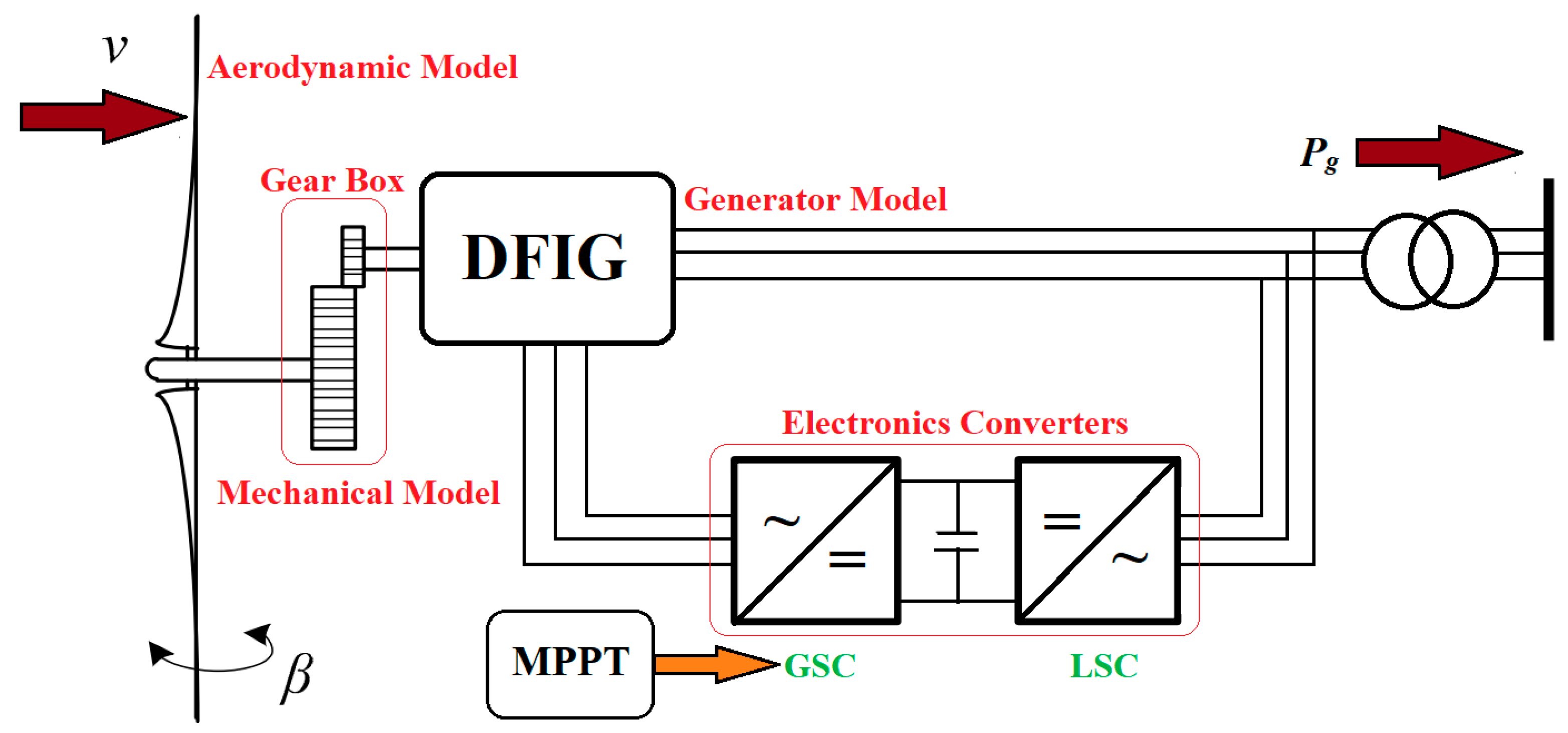
2.1. Wind Turbine (WT) Modeling

WTs have the capability to generate electricity by extracting wind kinetic energy (W.K.E). Therefore, a Type 3 WT is considered in this study due to its several advantages, such as having (1) a lower power electronics converter, (2) less mechanical stress, (3) the capability of variable operational speed, and (4) higher efficacy [63,64]. Figure 2 and Figure 3 show general and simplified [65] schematics of the WT, respectively. Therefore, a detailed model of each sub-system of a wind turbine is discussed one by one below.

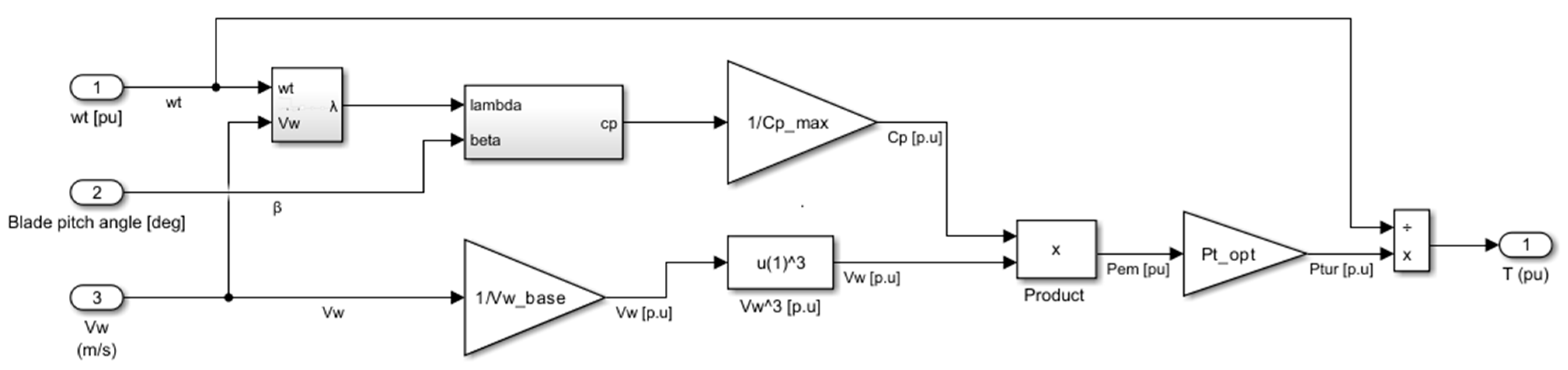
2.1.1. Aerodynamic Model

To develop the aerodynamic model of a wind turbine, the mathematical representation of wind power (power extracted from the wind) is given in Equation (1) [65]. Here, K p o w = 1 2   ρ · Π · R 2 P b a s e   W represents the power constant, vw is the wind speed, and Cp is the power coefficient. Similarly, ρ, R, λ, and β denote the air density (kg/m3), turbine radius (m), relative turbine speed (tip speed ratio), and blade pitch angle in degrees, respectively.
P t u r   p . u = K p o w v w 3 C p λ , β
where Cp is defined as the ratio of the extractable mechanical power to the power in the wind stream [66] or the power extraction efficiency of the wind turbine [67]. In [68,69], different models that represent Cp for three-bladed turbines are discussed. The most common is the model presented in Equation (3), where c1c6 are numerical constants, whose values are given in Table A2.
C p = c 1 c 2 λ i c 3 β c 4 c 5 λ i + c 6 λ
Here,
1 λ i = 1 λ + 0.08 β 0.035 β 3 + 1
Using the analytical method, it is found in the literature that Cp reaches its maximum at a particular air velocity ratio, i.e., v _ 2 / v _ 1 = 1 / 3 ; therefore, Cp,max is 0.593 [66]. This ideal value of Cp,max is called the “Betz factor”, after Betz, who first derived this ideal value. Thus, it is concluded that under ideal conditions, only 59.3% of the wind power is extractable from the wind in terms of mechanical energy. In real terms, the maximum extractable mechanical power or Cp should be less than these ideal conditions. Furthermore, it is clear in Equation (2) that the power coefficient Cp is a nonlinear function and depends on two factors: specific (or relative) turbine speed, λ, and blade pitch angle, β. Relative turbine speed, λ, is the ratio of the rotor blade tip speed to wind speed, Vw, as shown in Equation (7).
λ = K v   ω t   p . u v w   m s 1
where Kv denotes a speed constant, and it is the product of the base turbine speed, ωt,base [rad/s], and the diameter of the turbine, D[m] [70]. The dependence of the speed constant, Kv, on turbine diameter indicates that λ and Cp must be varied for each turbine due to the variation in turbine characteristics.
Figure 4 shows the graphical representation of Equations (2)–(4) in terms of Cp, β, and λ by using the values given in Table A2. It is clearly shown that the maximum achievable power coefficient value is 0.48 when the relative turbine speed and blade pitch angle of the turbine are 8.1 and 0 degrees, respectively. In other words, the maximum extractable mechanical power of the turbine from the available incident wind is 48%. It is important that Cp should be maintained at or close to Cp,max to obtain more power and capture more energy.
In addition, Figure 5 shows the relationship between Ptur and the variable range of wind speed and rotor speed. It clearly shows that at Vw = 12 ms−1, the optimum power is 0.73 pu, and the rotor speed is 1.2 pu. This rotor speed is the base rotor speed for this turbine. However, each curve in Figure 5 shows a specific optimal mechanical power and optimal rotor speed at defined wind speeds. It is important to consider that in all these curves, the blade pitch angle is zero. As described above, the VSWT DFIG model is represented per unit; therefore, ⍵t [p.u] in Figure 6 and ⍵g [p.u] in Figure 3 are equal.

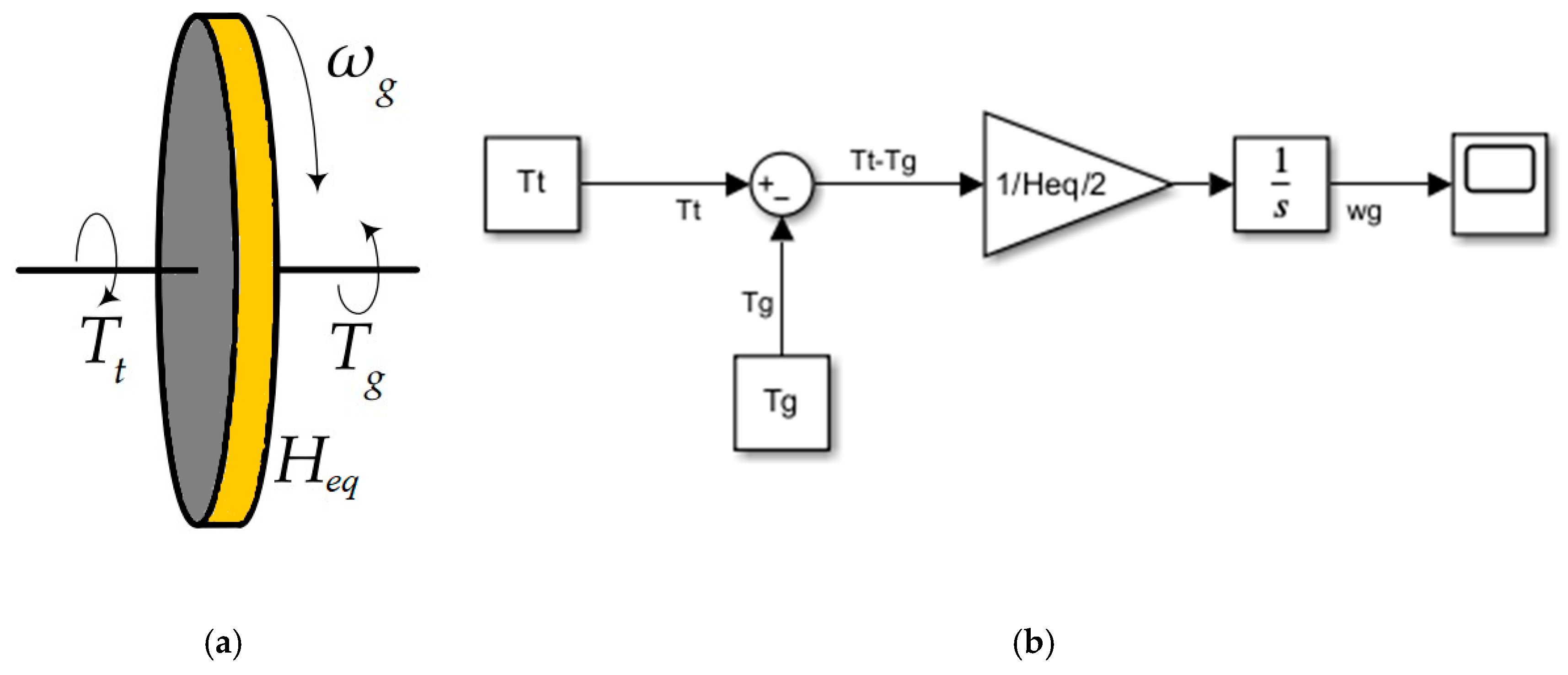
2.1.2. Mechanical Model

For PFC studies, both two- and one-mass mechanical rotor systems of the VSWT are found in [71,72]. However, to avoid the complexity of two-mass mechanical models in terms of mathematical representation, the authors prefer to use a one-mass system that results in better software implementation and system analysis [73,74,75]. Equation (5) represents the one-mass system mechanical model, where Heq represents the natural moment of inertia. The MATLAB Simulink representation of Equation (5) is shown in Figure 7b, which computes the rotor speed variation owing to the difference between the torque demanded by the converter and that provided by the wind turbine [72,76].
2 H e q d ω t d t = T t T g

2.1.3. DFIG and Converters

For PFC, it is not essential to consider the detailed short-term dynamics of voltages and currents involved in the machine. However, only the frequency behavior response to power is enough. That is why, for FR, the authors in [48,76,77,78] consider a first-order, single actuator with time constant, tc, that represents both the DFIG and converters, whose value is given in Table A2, as shown in Figure 8.

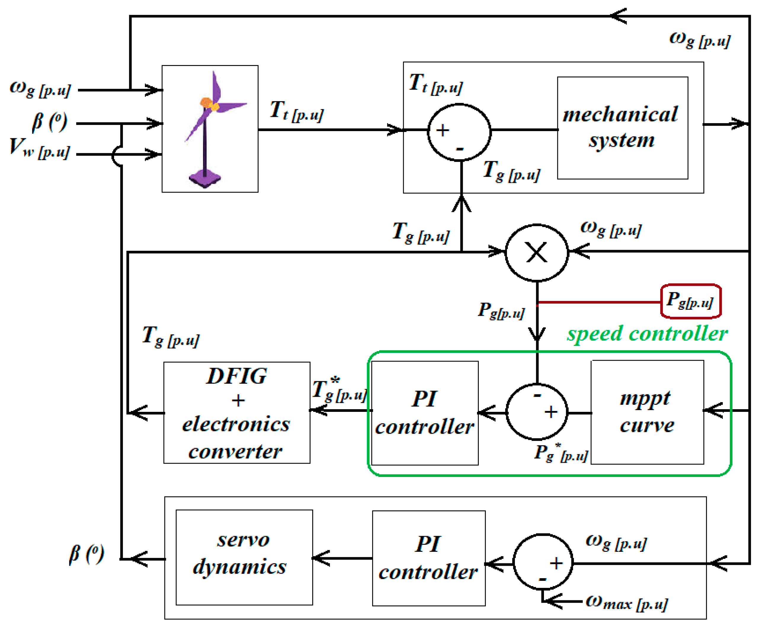
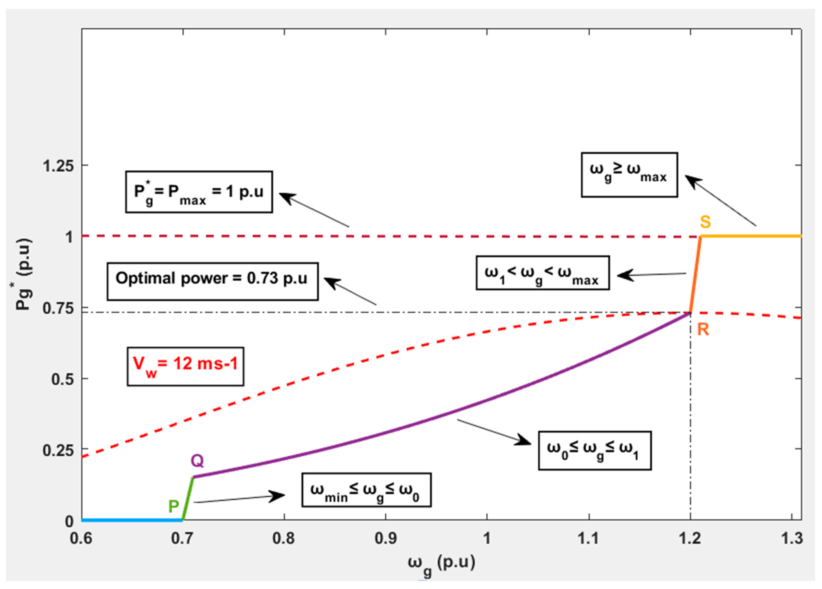
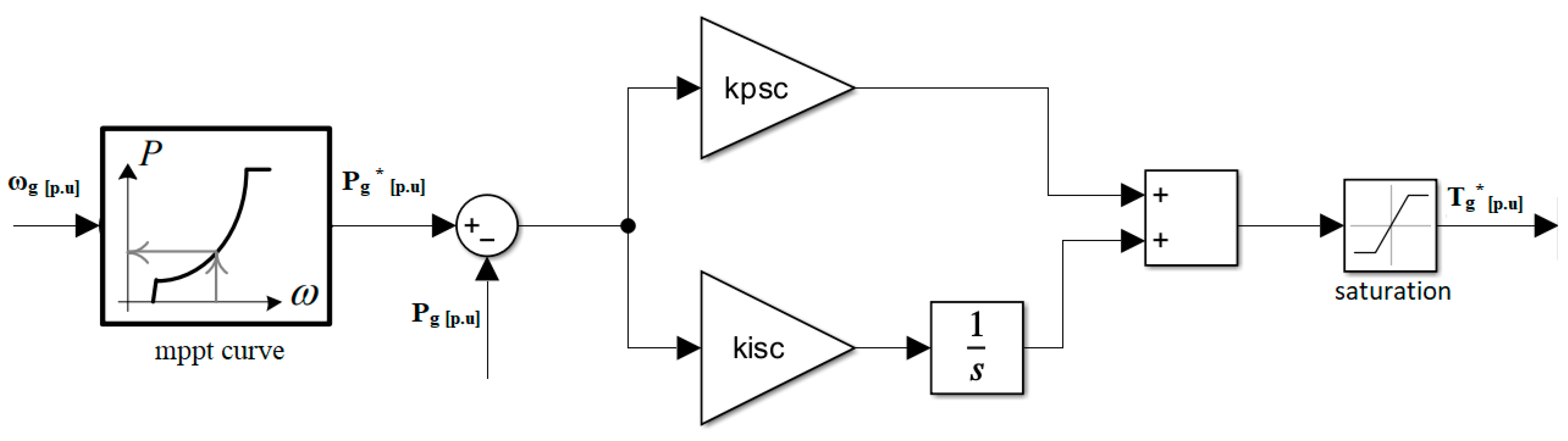
2.1.4. Maximum Power Point Tracking

VSWTs can change their rotational speed in response to wind variation for wind power extraction and maintain the tip speed ratio (TSR) [70]. To maintain this TSR during wind fluctuations, the rotational speed must be adjusted to extract maximum wind power [79]. This is performed by an MPPT system. An MPPT is an algorithm used to extract maximum power irrespective of the wind speed. In other words, the MPPT is a way to determine the optimal generator speed that ensures maximum power yield during wind variations [70,80]. Thus, according to [81], the dynamics of the MPPT curve are given by Equations (6)–(9), and their graphical representation is shown in Figure 9. Here, Kopt is called the optimization constant, which depends on turbine characteristics. ωmin and ωmax refer to the minimum and maximum rotor speeds against the cut-in wind speed Vw(cut-in) and cut-off wind speed Vw(cut-off), respectively. Under Vw(cut-in), the mechanical power is so low that it is not worth working, so it is preferred to shut down the turbine [82]. Similarly, beyond Vw(cut-off), also called the furling wind speed, the turbine should be stopped to avoid structural damage unless an advanced control of blade pitch angle acts on it.
P g * = K o p t ω 0 ω 0 ω m i n ω g ω m i n   w h e n   ω m i n ω g   ω 0
P g * = K o p t ω g 3   w h e n   ω 0 ω g   ω 1
P g * = P m a x K o p t ω 1 3 ω m a x ω 1 ω g ω m a x + P m a x   w h e n   ω 1 < ω g < ω m a x
P g * = P m a x   w h e n   ω g ω m a x
Section PQ in Figure 9 shows that the output power of the turbine follows a linear trend under low-wind conditions, represented by Equation (6). Similarly, section QR shows the MPPT region or optimization region in which the wind turbine provides power according to Equation (7). The wind turbine will operate under this criterion until the Vw reaches the pre-defined optimal value of Vw.base. Furthermore, section RS refers to constant speed and will maintain the turbine mechanical power at Pmax, as shown in Equation (8). In addition, this region is delimited by the maximum speed ωmax specified for the wind turbine within the thermal limits of the electrical generator. Equation (9) shows the constant power region with maximum power Pmax, when Vw exceeds the rated value, so that the generator and turbine are not overloaded and the dynamic load does not result in mechanical failure [70]. Blade pitch angle control, as discussed below (Section 2.1.5), will be activated in this region.
The MPPT ensures maximum power is generated according to wind variations. However, to achieve this, a speed controller is needed that ensures equilibrium is maintained between the actual generated available power and the reference power generated by the MPPT. Therefore, a PI-based speed controller is considered—it is widely used in wind generation applications [83]. Figure 10 shows the MATLAB Simulink representation of the speed controller exhibiting constants kpsc and kisc, whose values are given in Table A2. The output of this speed controller is a reference torque signal, which is an input for the DFIG, whose values are limited within a specific range according to the thermal limits of the generator.

2.1.5. Blade Pitch Angle Control (BPAC)

The role of BPAC is to limit the power generated by the turbine at Pmax during high-wind conditions. To justify this concept, let us consider Equation (9). During high winds, the maximum power generated by turbines is Pmax and remains constant at this specified value. This decompensation of powers translates, of course, into an angular over-acceleration on the axis of the turbine–generator assembly, causing the rotational speed to exceed the maximum value. To overcome this problem when it is not possible to increase power over the rated value, an auxiliary control system (BPAC) is needed. This system will change the pitch angle and, by doing so, reduce the wind power captured [84]. In addition, during uncertain conditions like a sudden loss of power or wind speed, BPAC also acts on the turbine power system to prevent wind turbine damage [77]. A conventional BPAC schematic is shown in Figure 11, where regulatory actions of the control system are governed by the PI controller together with the servo motor [85,86,87]. BPAC takes the difference in the rotor and maximum rotor reference speeds as an input and generates the blade pitch angle accordingly.

2.2. Modeling of Diesel Power Plant (DPP)

A DPP is a conventional power system source used to generate electrical power using fossil resources, i.e., diesel, as fuel. In isolated islands, it can be the only energy source, i.e., off-grid or isolated power system that fulfills the electrical power requirements of that area. Figure 12 shows the schematic of a diesel generator governor (DGG) used by us in our previous work [30]. It shows that the DGG has four different blocks, i.e., a speed governor (SG), actuator, crankshaft dynamics (CD), and diesel engine (DE). Here, t1, t2, and t3 represent time constants; HT is the inertial constant; Tm shows mechanical torque; and Te denotes the torque opposed by the electrical generator. In this study, we used the dynamic equations for a DPP given in [30], which are presented in Figure 12.

3. Proposed Hybrid Wind–Diesel Contribution to Frequency Regulation

The VSWT naturally does not contribute to FR or system inertia. This can be clearly justified in Figure 2, in which two models are used to provide control, i.e., the MPPT and blade pitch angle controller. According to Equations (6)–(9) (MPPT curve), the turbine reference generated power is independent of frequency deviation due to fast converter control [88,89]. Moreover, the slow mechanical power regulated by the BPAC cannot contribute to system power variation. Therefore, an advanced FD-based control scheme should be introduced in BPAC and a variable-speed operational controller to emulate the frequency response like that of synchronous generators using wind turbines.

3.1. BPAC with Pitch Compensation

Figure 11 shows the conventional BPAC that computes the variation between the maximum and generated rotor speeds. However, to contribute to primary frequency regulation, mechanical power control can be utilized by introducing pitch compensation with an additional PI controller [28,90], as shown in Figure 13. For each wind speed, pitch compensation computes the difference between Pmax and Pg.

3.2. VSWT Inertial and Proportional (I&P) Control Loops

VSWT inertial and proportional control loops play an important role in releasing the kinetic energy available in the wind turbine so that “hidden inertia or synthetic inertia (SI)” is accessible to the grid. In [91], SI is defined as the response of a generating unit to frequency changes, particularly a power exchange that is proportional to the rate of change of frequency (RoCoF). Furthermore, the controlled contribution of electrical power from a unit that quickly corrects FD is called a fast frequency response (FFR) [28]. In this paper, the proposed VSWT inertial and proportional control loops used to provide the RoCoF and FFR are given in Equation (10). Here, Kpn constantly weighs the FD, while Kdn weighs the RoCoF. The output of this I&P control loop is a torque signal ΔTn. Owing to the existence of a wind energy conversion system, the inertial and proportional control loops add a torque signal ∆Tn to the power reference output to be tracked by the converter [28,48].
Δ T n = [ K p n + K d n t ] ( f r e f f )
Therefore, after the addition of the proposed VSWT I&P control loops, the torque supplied to the DFIG and converters will be the sum of both the proposed torque and mechanical torque (Figure 2) generated by the PI controller or speed controller, represented by Equation (11) and shown in Figure 14.
T t o t a l = T n o + Δ T e m + Δ T n

4. Controller Tuning Methodology

Based on the above-mentioned proposed control loops of inertial and proportional control for VSWTs, a Student-Psychology-Based Algorithm (SPBA) is proposed here, as presented in [30]. The main advantage of this SPBA is that it provides the best optimum combination of gains for PI controllers. However, different nature-inspired algorithms like the bat algorithm [92], partial swarm optimization algorithm [93,94], GA-PSO [95,96], and GA fuzzy [97] are discussed in the literature. However, the SPBA approach is very effective towards this aim [30].
The proposed SPBA used objective functions to calculate the best optimum gain combination to provide FR during transients. The objective function includes the integral absolute error (IAE), integral square error (ISE), and minimum FD. The proposed SPBA helps the I&P control in providing earlier frequency support by releasing a fraction of the K.E stored in rotational masses and taking advantage of the rapid response capability associated with power electronics-based controlled converters. The mathematical representations of the IAE and ISE are given in Equations (12) and (13), respectively. Based on these objective functions, a control quality index, Z, was introduced that estimates the controller’s effective performance. Equation (14) shows the controller quality index Z. Here, NADIR represents the underfrequency, and c represents the number of transient peaks (both +ive and −ive) in the speed derivative during contingency. With the help of the control quality index, distinctive combinations of controller gains are calculated. The benefit of using the SPBA is to provide a combined optimum solution if one or more controllers are tuned simultaneously. Figure 15 presents a flow chart of the SPBA for one controller with two gain parameters (Kdn and Kpn). However, with the increased number of controllers, the number of possible gain parameter combinations increased. In the current scenario, for a controller of two gain parameters, there are eight possible conditions to find the best suitable behavior of the controller. In Section 4.2, the same two parameters based on the SPBA tuning methodology were used to find the optimal values of the inertial and proportional controllers. It is clearly shown in Figure 15 that the algorithm first calculates the base parameters and then compares them with the individual controller quality index, Z, produced by each conditional loop. The decision to repeat the simulation with or without incremental gain parameters depends on Y. Y = [0] indicates repeat simulation by reducing the increment up to the first decimal place. On the contrary, it returns greater Z values because they lead to better controller performance. In addition, comparing it with the previous controller quality index, if the result is positive, the objective function values of Zprev are replaced with the new values associated with Znew. The significance of this replacement is that the new gain parameter values are closer to the optimal unique solution. Every time Znew > Zprev, the system performance is enhanced by shifting closer to the stability point. The simulation will be stopped when two conditions are satisfied: The first is when incremental conditions are met. It is 0.01 in the current scenario, beyond which there is no significant improvement in NADIR and Z. The second is when Znew ≯ Zprev. After satisfying these conditions, the final Z reflects the optimum solution with the combined effect of lower fluctuations in the IAE and ISE. The main benefit of this approach is that researchers can find a unique optimum solution with a fast frequency response for PFC. Another significance of the importance of this algorithm is that the system becomes more stable than in the previous condition during each simulation. If the gain parameters decrease or increase from the final optimal point or controller gain combination, the results become worse, enhancing the FD, transient settling time, and oscillations. These observations are discussed later in this paper. Moreover, in Equation (14), the highest value of Z indicates a better controller performance.
I A E = 0 t s i m | ω e ( t ) | d t
I S E = 0 t s i m ω e ( t ) 2 d t
Z = N A D I R I A E · I S E · c

4.1. Base Case: FR Provided by Diesel Governor

We consider a base case without the control loops proposed in Section 5 to highlight the main contribution of VSWTs for FR. However, during the absence of the proposed control loops, all FR will be provided by the diesel governor. To validate the base case of the VSWT hybrid wind–diesel power system, we used a step response of 0.5 pu (starts from 1.1 to 1.6 p.u) as Pload. This step response depicts the loss of wind generation and results in an increased load to the DPP and FD. Furthermore, the wind power plant is initialized at 0.70 p.u for the base case and onwards in this study. Figure 16 shows the performance of hybrid systems during increased load demand. Similarly, Table 2 presents the values of several parameters (NADIR, ISE, IAE) during a sudden increase in load demand.

4.2. Case A: VSWT Contribution to FR Using Proposed Control Without Tuning Diesel Governor Gain Parameters

In this case, the VSWT uses proposed inertial and proportional control loops and pitch compensation to provide synthetic inertia and pitch angle smoothing. However, the diesel governor gain parameters remain the same. To provide synthetic inertia, the gain parameters of the VSWT inertial and proportional control tuned by the proposed tuning methodology are discussed in Section 5. Using the SPBA tuning methodology, optimal tuning values for inertial and proportional control gains, i.e., Kdn = 0.03 and Kpn = 0.1, were calculated. Similarly, the BPAC was also tuned due to an additional pitch angle compensation controller. However, the BPAC (Figure 13) shows a better response with integral control instead of the proposed PI controller, in the pitch compensation loop (i.e., Kpc = 0), which further simplifies the VSWT model. The new tuned gain parameters of the modified BPAC are given in Table A3. Therefore, with the proposed approach (without the variation in DG parameters), the new speed is 0.957646 p.u, and the NADIR is 57.45876 Hz. This clearly shows that the contribution of synthetic inertia is negligible (frequency improvement of 0.00222 Hz) when compared to the base case (Section 5.1). One of the main reasons for this negligible contribution is the optimally tuned diesel governor (we already tuned this in [30]), which mainly assists in providing inertia during transients in hybrid power systems. We finally conclude that the VSWT does not provide a significant contribution to synthetic inertia in hybrid mode with the diesel power plant when the diesel governor is optimally tuned. In other words, to benefit from the VSWT for FR, the hybrid model will be tuned in combination when the DG works with optimally tuned gain parameters.

4.3. Case B: VSWT Contributes to FR by Tuning the Proposed Controls and Diesel Governor Gain Parameters in Combination

In this case, we considered both proposed control loops and diesel governor gain parameters and tuned the whole system in combination to make the hybrid power system effective during transients. The same proposed tuning methodology of the SPBA (discussed in Section 5) is used to simultaneously tune four parameters (Kdn, Kpn, Ki_d, and Kp_d). The first two gain parameters (Kdn and Kpn) belong to inertial and proportional control loops of the VSWT, but the latter two parameters (Ki_d and Kp_d) represent the gains of the diesel governor. As mentioned above, the proposed SPBA methodology calculates the controller quality index, Z, for thousands of different gain combinations. As a result, a unique combination of gain parameters was found that reflects the minimum FD and reduced or low ISE and IAE during transients. To achieve this unique combination, we considered again a step response of 0.5 p.u (starts from 1.1 to 1.6 p.u) as Pload. After testing a series of combinations, the controller quality index improves, as shown in Figure 17, with gain parameter values of Kdn = 0.47, Kpn = 9, Ki_d = 14.89, and Kp_d = 21.01. Now, the frequency deviation is reduced by 1.8% compared to the base case. This means that the frequency response improved by 1.05 Hz (58.51224 Hz versus 57.45654 Hz). Similarly, the ISE and IAE were reduced by 16.75 and 159.65%, respectively. Furthermore, the inertial and proportional control loop (Figure 14) contribution against the 0.5 p.u increase in load demand is shown in Figure 18. In addition, the hybrid WDPS provides FR support to a maximum load increment of 0.6 p.u (at 10 s) (390 kW at rated power). The effect of pitch compensation is discussed in Section 5. Table 3 shows the various parameters of hybrid WDPS in this scenario (Case B).

5. Results and Discussion

According to Jones et al. [98], perturbations like step, ramp, and random signals are enough to validate the suitability of controller tuning. Based on this approach, the performance of the PI controllers of La Palma Island used for FR under various scenarios of renewable energy generation was simulated [99]. Furthermore, in [28], a nonlinear model was simulated by assuming a step response as the load demand increment (due to a sudden loss of wind generation), a ramp response (a gradual increment in Vw), and a random response (wind fluctuations) as a realistic event. The same methodology was also used in [89]. Therefore, the same approach was used in this study to validate the controller and VSWT WDPS model performance. However, we differentiated these above-mentioned conditions into normal and abnormal operating conditions. In addition, further simulation was also performed to simultaneously verify the hybrid model’s performance and stability during real-world scenarios, i.e., combined variations in load demand and wind fluctuations.

5.1. VSWT Hybrid WDPS Performance Under Normal Conditions

In this case, we considered both the ramp and random response (normal conditions) as real-world scenarios for hybrid WDPSs. A gradually increased ramp response applied as a wind speed to the VSWT reflects the increase in wind speed during a windy storm or windy season. However, random signals are applied to the VSWT to reflect wind speed fluctuations. The detailed effect of each response is discussed one by one below.

5.1.1. Ramp Response

To justify the performance of WDPSs and particularly their BPAC during windstorms, we consider a ramp signal (0.2634 ms−2) as the wind speed for 50 s, as shown in Figure 19. It is noted that the cut-out wind speed of the VSWT model [65] is 25 ms−1, given in [100]. Because of the linear increase in wind speed, the turbine-generated power will increase until its maximum value, i.e., 1 pu. However, with the increase in Pwind, the DPP should reduce its generation to maintain the system frequency. With the further increase in wind speed after the wind turbine achieves its maximum limit, Pmax, BPAC activates, as shown in Figure 20. Due to the modified BPAC (specifically, the power compensation control loop), the beta rotation is much smoother.

5.1.2. Random Response

Wind is intermittent by nature. Therefore, wind speed is not steady but varies with time. To reflect this event, random wind speed is considered a real-world scenario. In [101], the wind power-generated signal was considered a random response for simulation. However, to justify the performance of the hybrid WDPS, the random wind power response was considered a wind fluctuation in this study. Therefore, the low wind power fluctuation was converted into wind speed because wind power is directly proportional to the cube root of Vw. In addition, during very low winds, the beta and power coefficient may not affect this proportionality relation. Then, this trend was scaled up to cover the range of low, medium, and high wind speeds, as shown in Figure 21. Different parameters against wind fluctuations are shown in Figure 22, which indicate that the modified VSWT hybrid WDPS performed efficiently in wind variations. The DPP frequency seems to be stable in such events. However, the frequency deviations shown at 800 s and 2000 s result in a sudden loss of wind power generation. Wind generation drops because the wind speed drops below the rated wind speed. This results in a sudden increase in load demand to the DPP shown in Figure 22. Similarly, the effectiveness of inertial and proportional control and blade pitch angle control is presented in Figure 23. Figure 24 shows a detailed graphical representation of that load demand event. The results clearly depict the contribution of the proposed VSWT inertial and proportional control of almost 0.15 p.u during the reduction in wind generation. It is also concluded that the contribution of proportional control, Kpn, is much higher compared to Kdn. In other words, the VSWT efficiently contributes to the fast frequency response.

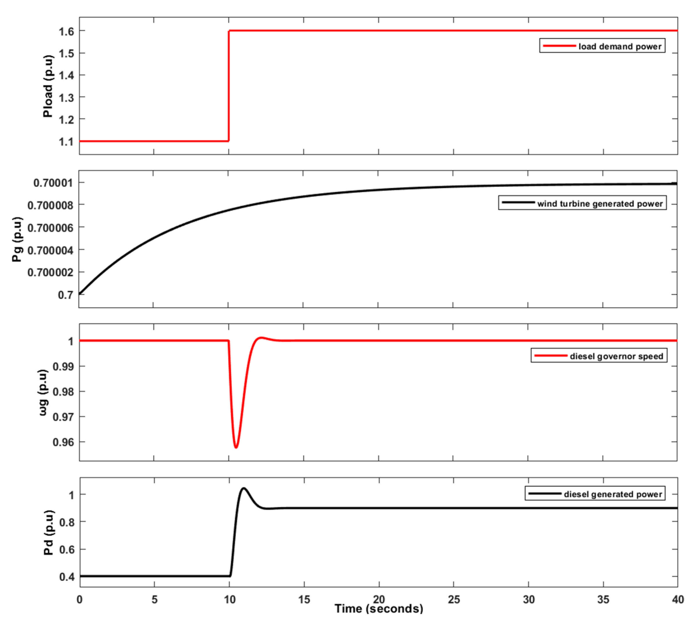
5.2. VSWT Hybrid WDPS Performance Under Abnormal Conditions

A sudden increase in load demand or loss of wind generation is considered an abnormal condition for hybrid systems. However, this case was already discussed in Section 4.3 by considering a step response of 0.5 pu as an increase in load demand. In addition, different strategies were discussed in the literature to validate the performance of VSWTs in load fluctuations. A step random signal in [24] and a random signal in [102] from the MATLAB library are used as load variation. In fact, random signals generated by MATLAB are also a random step response. Therefore, a step random signal considered as load variation, shown in Figure 25, is assumed to reflect the real-world scenario. Load variation dramatically affects the system frequency. During such contingencies, the VSWT also provides synthetic inertia using an inertial and proportional control loop (Figure 14) in addition to the inertial support provided by the DG itself. Figure 25 justifies this statement.

5.3. VSWT Hybrid WDPS Performance During Simultaneous Fluctuations in Wind Speed and Load Demand

Wind speed and load demand in the WDPS power system do not remain constant but vary with time due to diverse consumption and seasonal dependence. Therefore, to ensure the hybrid WDPS performance is close to reality, the combined effect of fluctuating wind and load demand is considered. A random response for both wind speed and load variation is considered, which reflects all the possible conditions of real-world events, i.e., load increase but wind decrease or vice versa, both load and Vw increase or decrease, etc. Figure 26 shows the system’s behavior during fluctuating wind speed and load demand. Both wind and diesel power plants work efficiently and fulfill the load demand. A physical limit for both power plants is important in terms of their generation. Both power plants produced a maximum of 1 pu each. However, the DPP produced the maximum 1 pu difference in power according to Equation (15). Similarly, wind turbines must also be limited due to the maximum allowable pitch angle rotation and wind speed.
Pload [p.u] = Pwind [p.u] + Pd [p.u]

5.4. Summarized Discussion

In this section, we summarize various findings regarding the hybrid WDPSs of San Cristobal Island. As mentioned above, naturally, a DPP has the capability to provide inertial support in hybrid generation because WTs do not contribute, due to the presence of fast-acting power electronics converters. This same scenario (a WT without the proposed control) is discussed in Section 4.1 (base case), and it is clearly observed that the frequency deviation in this case is 2.5435 Hz against a 0.5 pu variation in load demand. It is important to mention that the DPP is optimally tuned in this case. However, to highlight the effects of the proposed controls, we introduced such a control in a VSWT and optimally tuned it, using the SPBA (case A). The results show that the NADIR is 2.54124 Hz against the same 0.5 p.u load demand variations. This means that the VSWT contribution is minor, and the FD reduction is just 0.00222 Hz. One of the main reasons for this negligible contribution is the optimally tuned diesel governor, which mainly assists in providing inertia during transients in hybrid power systems. We finally conclude that the VSWT does not provide significant contributions for releasing synthetic inertia in hybrid mode when the diesel governor is optimally tuned. In other words, to benefit from the VSWT for FR, the hybrid model should be simultaneously tuned. With this aim, both the VSWT and DG were simultaneously tuned (case B), and the results showed a significant reduction in FD, i.e., 1.8% (from 2.5435 to 1.48776 Hz) against 0.5 pu, compared to the base case. Moreover, several other parameters, like the ISE and IAE, were also improved during this global optimization of hybrid WDPSs. In general, it is concluded that the VSWT can make significant contributions by releasing synthetic inertia during contingencies when both power plants are optimally tuned. It is important to mention that the real parameters of the San Cristobal WDPS are used in this study as a case study; however, this topology of the proposed control and SPBA can be generally implemented in any power system.

6. Limitations and Future Work

In this section, we summarize several limitations and the future of WDPSs. Generally, a hybrid isolated WDPS is developed with an aim to achieve maximum generation benefits from RE resources. However, the penetration of RE resources has certain limitations and varies from system to system. Based on this concept, the conventional DPP used in this study has minimum operational limits of 30% of the full load. This means the maximum variable load demand is 0.7 pu irrespective of the wind generation. Moreover, the simplified model of the DFIG and converters in the VSWT restricts its usage in carrying out studies within the time horizon that covers primary frequency control actions. This means that it is not useful for other types of analysis, such as voltage control, short circuit, protections, and harmonics. Furthermore, the SPBA also has certain limits, solely depending on the number of controllers tuned at a time, because the increased number of controllers significantly enhances the number of variables, which increases the complexity and computational time. Regarding future directions, we recommend including the energy storage system with the aim of providing the frequency regulations. Moreover, the consideration of flexible alternative current transmission system (FACTS) devices can be an option to increase system stability and reliability. Finally, the hybrid system can be tested because hardware in a loop (HIL) in certain real-world environments, like OPAL-RT, can be valuable.

7. Conclusions

In this paper, various control strategies, i.e., inertial and proportional (droop) control and pitch compensation control, are proposed for VSWTs to provide frequency regulation. Based on these proposed control loops, the VSWT can release synthetic inertia in a hybrid WDPS of San Cristobal Island and help stabilize the system frequency during wind fluctuations and power imbalances. An SPBA-based tuning methodology is adopted to tune the hybrid VSWT WDPS. This SPBA methodology tuned the proposed control loops based on numerous performance indices, i.e., IAE, ISE, and controller quality index, Z. The main benefit of adopting this methodology is that it provides an optimal solution for the proposed control and enhances hybrid system effectiveness and stability. The system’s behavior tended to become worse in terms of frequency deviation, increased settling time, and increased oscillations if we increased or decreased the gain parameters from the proposed optimum values. This result shows the distinctiveness and usefulness of the optimum solution generated by the SPBA. With the SPBA, the proposed pitch compensation, which enhanced the effectiveness and smoothness of the BPAC, was further simplified, resulting in a reduction in hybrid system complexity. Furthermore, hybrid WDPS tests (real-world scenarios) were conducted under various sets of perturbations, i.e., step (sudden loss of wind generation), ramp (steady decrease in wind power), and random (wind and/or load variations). These perturbations were applied as wind speed in the VSWT and a power imbalance to the DPP in hybrid WDPSs. In the case of a 0.5 pu increase in load demand, the FD was reduced by 1.8% (1.05 Hz). In addition, the reductions in the other quality indices, IAE, ISE, and Z, were 159.65, 16.75, and 83.80%, respectively. Furthermore, it is concluded that the system is stable until the variation in load demand is 0.6 pu. Furthermore, the proposed control loop result under various real-world scenarios (random wind and/or load variations) justifies the PFC support provided to the hybrid WDPS. In summary, the simulation results illustrate the effectiveness of hybrid WDPS performance for FR.

Author Contributions

Conceptualization, J.Á.S.-F.; methodology, J.Á.S.-F. and M.A.; software, M.A. and J.Á.S.-F.; validation, M.A. and J.Á.S.-F.; formal analysis, M.A. and J.Á.S.-F.; investigation, M.A. and J.Á.S.-F.; resources, J.Á.S.-F.; data curation, M.A. and J.Á.S.-F.; writing—original draft preparation, M.A. and J.Á.S.-F.; writing—review and editing, J.Á.S.-F.; visualization, M.A. and J.Á.S.-F.; supervision, J.Á.S.-F.; project administration, J.Á.S.-F.; funding acquisition, J.Á.S.-F. All authors have read and agreed to the published version of the manuscript.

Funding

This research was funded by Universidad Politécnica de Madrid under grant number RP2304330031.

Institutional Review Board Statement

Not applicable.

Informed Consent Statement

Not applicable.

Data Availability Statement

All the data supporting the reported results can be found in this paper and the cited references.

Conflicts of Interest

The authors declare no conflicts of interest. The funders had no role in the design of the study; in the collection, analysis, or interpretation of the data; in the writing of the manuscript; or in the decision to publish the results.

Appendix A

Table A1. Dataset of installed DPP [30].
ParametersValues and Units
Model of diesel engineCAT-3512 DITA
Capacity813 kVA
Rated power650 kW
Rated frequency60 Hz
Synchronous speed1200 rpm
Constant of inertia (HT)0.4208 s
Torque min/max (Tmin/Tmax)0/1.1 pu
Time constants: t1, t2, t30.024 s, 0.1 s, 0.01 s
Output voltage480 V ± 5%
Table A2. Dataset of installed VSWT [65].
ParametersValues and Units
Base power (Pbase)1.5 MW
Generator min/max power (Pg,min/Pg,max)0.04/1 pu
Generator base speed (ωg,base)157.08 rad/s
Air density1.225 kg∙m−3
Speed constant (Kλ)63.29 ms−1
Rotor diameter (D)77 m
Nominal frequency50 Hz
Nominal wind speed (at Pg = 0.73 p.u)12 ms−1
Generator min/max torque0.057/0.826 p.u
Turbine base speed (ωt,base)1.644 rad/s
Blade pitch angle min/max0/450°
Inertial constant (Heq)5.29 s
Gain parameters of speed controller (Kisc/Kpsc)8/0.3
Time constant of blade pitch servo motor (tp)0 s
Gain parameters of blade pitch controller (Kppc/Kipc)0/500
Blade pitch angle rate min/max (/dt)±2°/s
MPPT optimization constant (Kopt)0.4225
MPPT constants c1, c2, c3, c4, c5, c60.5176, 116, 0.4, 5, 21, 0.0068
MPPT curve speed limits ωmin, ω0, ω1, ωmax0.7 p.u, 0.71 p.u, 1.2 p.u, 1.21 p.u
Table A3. Dataset of modified parameters of VSWT hybrid WDPS using SPBA.
ParametersValues
Gain parameter of DG (Kp_d/Ki_d)21.01/14.89
VSWT I&P control gain parameters (Kpn/Kdn)9/0.47
Pitch compensation gains parameters (Kpc/Kic)0/80
BPAC gain parameters (Kppc/Kipc)6000/1400

References

  1. Asad, M. Improving Power Flow Using Static Synchronous Series Compensator. Egypt. J. Eng. Sci. Technol. 2021, 33, 69–74. [Google Scholar] [CrossRef]
  2. Hoseinzadeh, S.; Nastasi, B.; Groppi, D.; Astiaso Garcia, D. Exploring the Penetration of Renewable Energy at Increasing the Boundaries of the Urban Energy System—The PRISMI plus Toolkit Application to Monachil, Spain. Sustain. Energy Technol. Assess. 2022, 54, 102908. [Google Scholar] [CrossRef]
  3. Dalala, Z.; Al-Omari, M.; Al-Addous, M.; Bdour, M.; Al-Khasawneh, Y.; Alkasrawi, M. Increased Renewable Energy Penetration in National Electrical Grids Constraints and Solutions. Energy 2022, 246, 123361. [Google Scholar] [CrossRef]
  4. Terlouw, T.; Savvakis, N.; Bauer, C.; McKenna, R.; Arampatzis, G. Designing Multi-Energy Systems in Mediterranean Regions towards Energy Autonomy. Appl. Energy 2025, 377, 124458. [Google Scholar] [CrossRef]
  5. Deng, X.; Lv, T. Power System Planning with Increasing Variable Renewable Energy: A Review of Optimization Models. J. Clean. Prod. 2020, 246, 118962. [Google Scholar] [CrossRef]
  6. Impram, S.; Varbak Nese, S.; Oral, B. Challenges of Renewable Energy Penetration on Power System Flexibility: A Survey. Energy Strategy Rev. 2020, 31, 100539. [Google Scholar] [CrossRef]
  7. Matsumoto, K.; Matsumura, Y. Challenges and Economic Effects of Introducing Renewable Energy in a Remote Island: A Case Study of Tsushima Island, Japan. Renew. Sustain. Energy Rev. 2022, 162, 112456. [Google Scholar] [CrossRef]
  8. Zhang, Z.-S.; Sun, Y.-Z.; Lin, J.; Li, G.-J. Coordinated Frequency Regulation by Doubly Fed Induction Generator-Based Wind Power Plants. IET Renew. Power Gener. 2012, 6, 38. [Google Scholar] [CrossRef]
  9. Kies, A.; Schyska, B.; von Bremen, L. Curtailment in a Highly Renewable Power System and Its Effect on Capacity Factors. Energies 2016, 9, 510. [Google Scholar] [CrossRef]
  10. Asad, M.; Sanchez-Fernandez, J.A. Enhancing Frequency Regulation Support through Several Synthetic Inertial Approaches for WDPS. Electronics 2024, 13, 852. [Google Scholar] [CrossRef]
  11. Samala, N.; Bethi, C. Harnessing Synergy: A Holistic Review of Hybrid Renewable Energy Systems and Unified Power Quality Conditioner Integration. J. Electr. Syst. Inf. Technol. 2025, 12, 4. [Google Scholar] [CrossRef]
  12. Rahman, A.; Farrok, O.; Haque, M.M. Environmental Impact of Renewable Energy Source Based Electrical Power Plants: Solar, Wind, Hydroelectric, Biomass, Geothermal, Tidal, Ocean, and Osmotic. Renew. Sustain. Energy Rev. 2022, 161, 112279. [Google Scholar] [CrossRef]
  13. Guerra, O.J.; Zhang, J.; Eichman, J.; Denholm, P.; Kurtz, J.; Hodge, B.-M. The Value of Seasonal Energy Storage Technologies for the Integration of Wind and Solar Power. Energy Environ. Sci. 2020, 13, 1909–1922. [Google Scholar] [CrossRef]
  14. Qi, Y.; Wang, D.; Wang, X.; Jia, H.; Pu, T.; Chen, N.; Liu, K. Frequency Control Ancillary Service Provided by Efficient Power Plants Integrated in Queuing-Controlled Domestic Water Heaters. Energies 2017, 10, 559. [Google Scholar] [CrossRef]
  15. Prabhakar, K.; Jain, S.K.; Padhy, P.K. Inertia Estimation in Modern Power System: A Comprehensive Review. Electr. Power Syst. Res. 2022, 211, 108222. [Google Scholar] [CrossRef]
  16. Andersson, G.; Donalek, P.; Farmer, R.; Hatziargyriou, N.; Kamwa, I.; Kundur, P.; Martins, N.; Paserba, J.; Pourbeik, P.; Sanchez-Gasca, J.; et al. Causes of the 2003 Major Grid Blackouts in North America and Europe, and Recommended Means to Improve System Dynamic Performance. IEEE Trans. Power Syst. 2005, 20, 1922–1928. [Google Scholar] [CrossRef]
  17. Martins, A.C.B.; Gomes, P.; Guarini, A.; Alves, F.; Martins, N.; Djalma, F.; Taranto, G.N.; Ribeiro, C. Lessons Learned in Restoration from Recent Blackout Incidents in Brazilian Power System. In Proceedings of the 44th International Conference on Large High Voltage Electric Systems 2012, Paris, France, 26–31 August 2012. [Google Scholar]
  18. Rampurkar, V.; Pentayya, P.; Mangalvedekar, H.A.; Kazi, F. Cascading Failure Analysis for Indian Power Grid. IEEE Trans. Smart Grid 2016, 7, 1951–1960. [Google Scholar] [CrossRef]
  19. Ochoa, D.; Martinez, S. Proposals for Enhancing Frequency Control in Weak and Isolated Power Systems: Application to the Wind-Diesel Power System of San Cristobal Island-Ecuador. Energies 2018, 11, 910. [Google Scholar] [CrossRef]
  20. Report on Blackout in Turkey on 31 St March 2015-Final Version 1.0-Project Group Turkey. 2015. Available online: https://eepublicdownloads.entsoe.eu/clean-documents/SOC%20documents/Regional_Groups_Continental_Europe/20150921_Black_Out_Report_v10_w.pdf (accessed on 3 March 2025).
  21. Yan, R.; Masood, N.-A.; Kumar Saha, T.; Bai, F.; Gu, H. The Anatomy of the 2016 South Australia Blackout: A Catastrophic Event in a High Renewable Network. IEEE Trans. Power Syst. 2018, 33, 5374–5388. [Google Scholar] [CrossRef]
  22. Schmelter, A.; Mohd, A.; Ortjohann, E.; Hamsic, N.; Mohd, A.; Ortjohann, E.; Schultze, E.; Tuckey, A.; Zimmermann, J. Stabilising the Grid Voltage and Frequency in Isolated Power Systems Using a Flywheel Energy Storage System; The Great Wall World Renewable Energy Forum: Beijing, China, 2006. [Google Scholar]
  23. Delille, G.; Francois, B.; Malarange, G. Dynamic Frequency Control Support by Energy Storage to Reduce the Impact of Wind and Solar Generation on Isolated Power System’s Inertia. IEEE Trans. Sustain. Energy 2012, 3, 931–939. [Google Scholar] [CrossRef]
  24. Mi, Y.; Xu, Y.; Lang, Z.; Yang, X.; Ge, X.; Fu, Y.; Jin, C. The Frequency-Voltage Stability Control for Isolated Wind-Diesel Hybrid Power System. Electr. Power Syst. Res. 2021, 192, 106984. [Google Scholar] [CrossRef]
  25. Shezan, S.K.A. Feasibility Analysis of an Islanded Hybrid Wind-Diesel-Battery Microgrid with Voltage and Power Response for Offshore Islands. J. Clean. Prod. 2021, 288, 125568. [Google Scholar] [CrossRef]
  26. Kumar, N.K.; Gopi, R.S.; Kuppusamy, R.; Nikolovski, S.; Teekaraman, Y.; Vairavasundaram, I.; Venkateswarulu, S. Fuzzy Logic-Based Load Frequency Control in an Island Hybrid Power System Model Using Artificial Bee Colony Optimization. Energies 2022, 15, 2199. [Google Scholar] [CrossRef]
  27. Nguyen Hong, N.; Nakanishi, Y. Optimal Scheduling of an Isolated Wind-Diesel-Energy Storage System Considering Fast Frequency Response and Forecast Error. Energies 2019, 12, 843. [Google Scholar] [CrossRef]
  28. Martínez-Lucas, G.; Sarasúa, J.; Sánchez-Fernández, J. Frequency Regulation of a Hybrid Wind–Hydro Power Plant in an Isolated Power System. Energies 2018, 11, 239. [Google Scholar] [CrossRef]
  29. Ejuh Che, E.; Roland Abeng, K.; Iweh, C.D.; Tsekouras, G.J.; Fopah-Lele, A. The Impact of Integrating Variable Renewable Energy Sources into Grid-Connected Power Systems: Challenges, Mitigation Strategies, and Prospects. Energies 2025, 18, 689. [Google Scholar] [CrossRef]
  30. Asad, M.; Martinez, S.; Sanchez-Fernandez, J.A. Diesel Governor Tuning for Isolated Hybrid Power Systems. Electronics 2023, 12, 2487. [Google Scholar] [CrossRef]
  31. Albadi, M.H.; El-Saadany, E.F. Overview of Wind Power Intermittency Impacts on Power Systems. Electr. Power Syst. Res. 2010, 80, 627–632. [Google Scholar] [CrossRef]
  32. Fernández-Guillamón, A.; Vigueras-Rodríguez, A.; Molina-García, Á. Analysis of Power System Inertia Estimation in High Wind Power Plant Integration Scenarios. IET Renew. Power Gener. 2019, 13, 2807–2816. [Google Scholar] [CrossRef]
  33. Lei, M.; Meng, K.; Feng, H.; Bai, J.; Jiang, H.; Zhang, Z. Flywheel Energy Storage Controlled by Model Predictive Control to Achieve Smooth Short-Term High-Frequency Wind Power. J. Energy Storage 2023, 63, 106949. [Google Scholar] [CrossRef]
  34. Bebars, A.D.; Eladl, A.A.; Abdulsalam, G.M.; Badran, E.A. Internal Electrical Fault Detection Techniques in DFIG-Based Wind Turbines: A Review. Prot. Control Mod. Power Syst. 2022, 7, 18. [Google Scholar] [CrossRef]
  35. Boyle, J.; Littler, T.; Foley, A.M. Coordination of Synthetic Inertia from Wind Turbines and Battery Energy Storage Systems to Mitigate the Impact of the Synthetic Inertia Speed-Recovery Period. Renew. Energy 2024, 223, 120037. [Google Scholar] [CrossRef]
  36. Quan, Y.; Hang, L.; He, Y.; Zhang, Y. Multi-Resonant-Based Sliding Mode Control of DFIG-Based Wind System under Unbalanced and Harmonic Network Conditions. Appl. Sci. 2019, 9, 1124. [Google Scholar] [CrossRef]
  37. Shen, Y.-W.; Ke, D.-P.; Sun, Y.-Z.; Kirschen, D.S.; Qiao, W.; Deng, X.-T. Advanced Auxiliary Control of an Energy Storage Device for Transient Voltage Support of a Doubly Fed Induction Generator. IEEE Trans. Sustain. Energy 2016, 7, 63–76. [Google Scholar] [CrossRef]
  38. Papadaki, A.; Savvakis, N.; Sifakis, N.; Arampatzis, G. Analysis of Hybrid Renewable Energy Systems for European Islands: Market Dynamics, Opportunities and Challenges. Sustain. Futures 2025, 9, 100601. [Google Scholar] [CrossRef]
  39. Alsharafi, A.; Besheer, A.; Emara, H. Primary Frequency Response Enhancement for Future Low Inertia Power Systems Using Hybrid Control Technique. Energies 2018, 11, 699. [Google Scholar] [CrossRef]
  40. Fernández-Guillamón, A.; Vigueras-Rodríguez, A.; Gómez-Lázaro, E.; Molina-García, Á. Fast Power Reserve Emulation Strategy for VSWT Supporting Frequency Control in Multi-Area Power Systems. Energies 2018, 11, 2775. [Google Scholar] [CrossRef]
  41. Fang, X.; Krishnan, V.; Hodge, B.-M. Strategic Offering for Wind Power Producers Considering Energy and Flexible Ramping Products. Energies 2018, 11, 1239. [Google Scholar] [CrossRef]
  42. Renuka, T.K.; Reji, P. Frequency Control of Wind Penetrated Hydro-Dominated Power System. In Proceedings of the 2015 International Conference on Technological Advancements in Power and Energy (TAP Energy), Kollam, India, 24–26 June 2015; pp. 316–321. [Google Scholar]
  43. Kasera, R.A.; Moses, P.M.; Wekesa, C. Frequency Stability of a Smart Grid with Solar Power Integration Using STATCOM. In Proceedings of the 2023 IEEE AFRICON, Nairobi, Kenya, 20–22 September 2023; pp. 1–6. [Google Scholar]
  44. Chen, K.; Miao, L.; Chen, D.; Qin, Y.; Jian, W.; Duan, K. Optimal Primary Frequency Regulation Control Strategy for Wind Farms to Prevent Secondary Frequency Drop. Adv. Comput. Mater. Sci. Res. 2025, 2, 133. [Google Scholar] [CrossRef]
  45. Abdeen, M.; Sayyed, M.; Dominguez-Garcia, J.L.; Kamel, S. Supplemental Control for System Frequency Support of DFIG-Based Wind Turbines. IEEE Access 2022, 10, 69364–69372. [Google Scholar] [CrossRef]
  46. Ekanayake, J.; Jenkins, N. Comparison of the Response of Doubly Fed and Fixed-Speed Induction Generator Wind Turbines to Changes in Network Frequency. IEEE Trans. Energy Convers. 2004, 19, 800–802. [Google Scholar] [CrossRef]
  47. Bonfiglio, A.; Invernizzi, M.; Labella, A.; Procopio, R. Design and Implementation of a Variable Synthetic Inertia Controller for Wind Turbine Generators. IEEE Trans. Power Syst. 2019, 34, 754–764. [Google Scholar] [CrossRef]
  48. Mauricio, J.M.; Marano, A.; Gomez-Exposito, A.; Martinez Ramos, J.L. Frequency Regulation Contribution Through Variable-Speed Wind Energy Conversion Systems. IEEE Trans. Power Syst. 2009, 24, 173–180. [Google Scholar] [CrossRef]
  49. Morren, J.; de Haan, S.W.H.; Kling, W.L.; Ferreira, J.A. Wind Turbines Emulating Inertia and Supporting Primary Frequency Control. IEEE Trans. Power Syst. 2006, 21, 433–434. [Google Scholar] [CrossRef]
  50. Singarao, V.Y.; Rao, V.S. Frequency Responsive Services by Wind Generation Resources in United States. Renew. Sustain. Energy Rev. 2016, 55, 1097–1108. [Google Scholar] [CrossRef]
  51. Shankar, G.; Mukherjee, V. Load Frequency Control of an Autonomous Hybrid Power System by Quasi-Oppositional Harmony Search Algorithm. Int. J. Electr. Power Energy Syst. 2016, 78, 715–734. [Google Scholar] [CrossRef]
  52. Guha, D.; Roy, P.K.; Banerjee, S. Frequency Control of a Wind-Diesel-Generator Hybrid System with Squirrel Search Algorithm Tuned Robust Cascade Fractional Order Controller Having Disturbance Observer Integrated. Electr. Power Compon. Syst. 2022, 50, 814–839. [Google Scholar] [CrossRef]
  53. Kumar, A.; Suhag, S. Whale Optimization Algorithm Optimized Fuzzy-PID Plus PID Hybrid Controller for Frequency Regulation in Hybrid Power System. J. Inst. Eng. Ser. B 2022, 103, 633–648. [Google Scholar] [CrossRef]
  54. Panwar, A.; Sharma, G.; Bansal, R.C. Optimal AGC Design for a Hybrid Power System Using Hybrid Bacteria Foraging Optimization Algorithm. Electr. Power Compon. Syst. 2019, 47, 955–965. [Google Scholar] [CrossRef]
  55. Monroy-Morales, J.L.; Peña-Alzola, R.; Sebastián-Fernández, R.; Campos-Gaona, D.; Castellano, J.Q.; Guardado, J.L. Frequency Control in an Isolated Wind-diesel Hybrid System with Energy Storage and an Irrigation Water Supply System. IET Renew. Power Gener. 2024, 18, 1040–1054. [Google Scholar] [CrossRef]
  56. Wu, L.; Infield, D. Power System Frequency Management Challenges—A New Approach to Assessing the Potential of Wind Capacity to Aid System Frequency Stability. IET Renew. Power Gener. 2014, 8, 733–739. [Google Scholar] [CrossRef]
  57. Wu, L.; Infield, D.G. Towards an Assessment of Power System Frequency Support From Wind Plant—Modeling Aggregate Inertial Response. IEEE Trans. Power Syst. 2013, 28, 2283–2291. [Google Scholar] [CrossRef]
  58. Gampa, S.R.; Das, D. Real Power and Frequency Control of a Small Isolated Power System. Int. J. Electr. Power Energy Syst. 2015, 64, 221–232. [Google Scholar] [CrossRef]
  59. Jazaeri, M.; Chitsaz, H. A New Efficient Scheme for Frequency Control in an Isolated Power System with a Wind Generator. Electr. Power Compon. Syst. 2011, 40, 21–40. [Google Scholar] [CrossRef]
  60. Ding, X.; Lin, W.; Xu, J.; Sun, Y.; Yao, L.; Mao, B. Coordinated Frequency Control for Isolated Power Systems with High Penetration of DFIG-Based Wind Power. CSEE J. Power Energy Syst. 2022, 10, 1399–1414. [Google Scholar] [CrossRef]
  61. Van de Vyver, J.; De Kooning, J.D.M.; Meersman, B.; Vandevelde, L.; Vandoorn, T.L. Droop Control as an Alternative Inertial Response Strategy for the Synthetic Inertia on Wind Turbines. IEEE Trans. Power Syst. 2016, 31, 1129–1138. [Google Scholar] [CrossRef]
  62. Vidyanandan, K.V.; Senroy, N. Primary Frequency Regulation by Deloaded Wind Turbines Using Variable Droop. IEEE Trans. Power Syst. 2013, 28, 837–846. [Google Scholar] [CrossRef]
  63. Xu, L.; Yao, L.; Sasse, C. Grid Integration of Large DFIG-Based Wind Farms Using VSC Transmission. IEEE Trans. Power Syst. 2007, 22, 976–984. [Google Scholar] [CrossRef]
  64. Muller, S.; Deicke, M.; De Doncker, R.W. Doubly Fed Induction Generator Systems for Wind Turbines. IEEE Ind. Appl. Mag. 2002, 8, 26–33. [Google Scholar] [CrossRef]
  65. Ochoa, D.; Martinez, S. Fast-Frequency Response Provided by DFIG-Wind Turbines and Its Impact on the Grid. IEEE Trans. Power Syst. 2017, 32, 4002–4011. [Google Scholar] [CrossRef]
  66. Hau, E.; Renouard, H. Physical Principles of Wind Energy Conversion. In Wind Turbines; Springer: Berlin/Heidelberg, Germany, 2006; pp. 81–89. [Google Scholar] [CrossRef]
  67. Munteanu, I.; Cutululis, N.-A.; Bratcu, I.A.; CeangĂ, E. Optimal Control of Wind Energy Systems; Springer: London, UK, 2008; ISBN 978-1-84800-079-7. [Google Scholar]
  68. Reyes, V.; Rodriguez, J.J.; Carranza, O.; Ortega, R. Review of Mathematical Models of Both the Power Coefficient and the Torque Coefficient in Wind Turbines. In Proceedings of the 2015 IEEE 24th International Symposium on Industrial Electronics (ISIE), Rio de Janeiro, Brazil, 3–5 June 2015; pp. 1458–1463. [Google Scholar]
  69. Schmidlin, C.R.; Lima, F.K.A. Wind Turbine and PMSG Dynamic Modelling in PSIM. IEEE Lat. Am. Trans. 2016, 14, 4115–4120. [Google Scholar] [CrossRef]
  70. Abdullah, M.A.; Yatim, A.H.M.; Tan, C.W.; Saidur, R. A Review of Maximum Power Point Tracking Algorithms for Wind Energy Systems. Renew. Sustain. Energy Rev. 2012, 16, 3220–3227. [Google Scholar] [CrossRef]
  71. Wilkie, J.; Leithead, W.E.; Anderson, C. Modelling of Wind Turbines by Simple Models. Wind. Eng. 1990, 14, 247–274. [Google Scholar]
  72. Perdana, A. Dynamic Models of Wind Turbines: A Contribution Towards the Establishment of Standardized Models of Wind Turbines for Power System Stability Studies; Department of Energy and Environment, Division of Electric Power Engineering, Chalmers University of Technology: Gothenburg, Sweden, 2008; ISBN 9789173852265. [Google Scholar]
  73. Bektache, A.; Boukhezzar, B. Nonlinear Predictive Control of a DFIG-Based Wind Turbine for Power Capture Optimization. Int. J. Electr. Power Energy Syst. 2018, 101, 92–102. [Google Scholar] [CrossRef]
  74. Mohapatra, S.P.; Dash, P.K.; Bisoi, R.; Sarangi, S.; Anjaiah, K. Fractional-Order Sliding Mode Control Based MPPT of a DFIG Connected to a Variable Speed Wind Turbine. In Proceedings of the 2022 2nd Odisha International Conference on Electrical Power Engineering, Communication and Computing Technology (ODICON), Bhubaneswar, India, 11–12 November 2022; pp. 1–5. [Google Scholar]
  75. Nanou, S.; Tsourakis, G.; Vournas, C.D. Full-Converter Wind Generator Modelling for Transient Stability Studies. In Proceedings of the 2011 IEEE Trondheim PowerTech, Trondheim, Norway, 19–23 June 2011; pp. 1–7. [Google Scholar]
  76. Miller, N.W.; Sanchez-Gasca, J.J.; Price, W.W.; Delmerico, R.W. Dynamic Modeling of GE 1.5 and 3.6 MW Wind Turbine-Generators for Stability Simulations. In Proceedings of the 2003 IEEE Power Engineering Society General Meeting (IEEE Cat. No.03CH37491), Online, 13–17 July 2003; pp. 1977–1983. [Google Scholar]
  77. Dharmawardena, H.; Uhlen, K.; Gjerde, S.S. Modelling Wind Farm with Synthetic Inertia for Power System Dynamic Studies. In Proceedings of the 2016 IEEE International Energy Conference (ENERGYCON), Leuven, Belgium, 4–8 April 2016; pp. 1–6. [Google Scholar]
  78. Ullah, N.R.; Thiringer, T.; Karlsson, D. Temporary Primary Frequency Control Support by Variable Speed Wind Turbines— Potential and Applications. IEEE Trans. Power Syst. 2008, 23, 601–612. [Google Scholar] [CrossRef]
  79. Hussain, J.; Mishra, M.K. Adaptive Maximum Power Point Tracking Control Algorithm for Wind Energy Conversion Systems. IEEE Trans. Energy Convers. 2016, 31, 697–705. [Google Scholar] [CrossRef]
  80. Bhowon, A.; Abo-Al-Ez, K.M.; Adonis, M. Variable-Speed Wind Turbines for Grid Frequency Support: A Systematic Literature Review. Mathematics 2022, 10, 3586. [Google Scholar] [CrossRef]
  81. Ochoa, D.; Martinez, S. A Simplified Electro-Mechanical Model of a DFIG-Based Wind Turbine for Primary Frequency Control Studies. IEEE Lat. Am. Trans. 2016, 14, 3614–3620. [Google Scholar] [CrossRef]
  82. Chinchilla, M.; Arnaltes, S.; Burgos, J.C. Control of Permanent-Magnet Generators Applied to Variable-Speed Wind-Energy Systems Connected to the Grid. IEEE Trans. Energy Convers. 2006, 21, 130–135. [Google Scholar] [CrossRef]
  83. Zhao, M.; Yuan, X.; Hu, J. Modeling of DFIG Wind Turbine Based on Internal Voltage Motion Equation in Power Systems Phase-Amplitude Dynamics Analysis. IEEE Trans. Power Syst. 2018, 33, 1484–1495. [Google Scholar] [CrossRef]
  84. Clark, K.; Nicholas, W.M.; Juan, J.S.-G. Modeling of GE Wind Turbine-Generators for Grid Studies. GE Energy 2010, 4, 0885-8950. [Google Scholar]
  85. Attya, A.B.; Hartkopf, T. Wind Turbine Contribution in Frequency Drop Mitigation—Modified Operation and Estimating Released Supportive Energy. IET Gener. Transm. Distrib. 2014, 8, 862–872. [Google Scholar] [CrossRef]
  86. Arnaltes, S.; Rodriguez-Amenedo, J.; Montilla-DJesus, M. Control of Variable Speed Wind Turbines with Doubly Fed Asynchronous Generators for Stand-Alone Applications. Energies 2017, 11, 26. [Google Scholar] [CrossRef]
  87. Sun, Y.; Zhang, Z.; Li, G.; Lin, J. Review on Frequency Control of Power Systems with Wind Power Penetration. In Proceedings of the 2010 International Conference on Power System Technology, Hangzhou, China, 24–28 October 2010; pp. 1–8. [Google Scholar]
  88. Aziz, A.; Than Oo, A.; Stojcevski, A. Frequency Regulation Capabilities in Wind Power Plant. Sustain. Energy Technol. Assess. 2018, 26, 47–76. [Google Scholar] [CrossRef]
  89. Martínez-Lucas, G.; Sarasúa, J.I.; Sánchez-Fernández, J.Á. Eigen Analysis of Wind–Hydro Joint Frequency Regulation in an Isolated Power System. Int. J. Electr. Power Energy Syst. 2018, 103, 511–524. [Google Scholar] [CrossRef]
  90. Ahmadyar, A.S.; Verbic, G. Control Strategy for Optimal Participation of Wind Farms in Primary Frequency Control. In Proceedings of the 2015 IEEE Eindhoven PowerTech, Eindhoven, The Netherlands, 29 June–2 July 2015; pp. 1–6. [Google Scholar]
  91. Eriksson, R.; Modig, N.; Elkington, K. Synthetic Inertia versus Fast Frequency Response: A Definition. IET Renew. Power Gener. 2018, 12, 507–514. [Google Scholar] [CrossRef]
  92. Yang, X.S. Bat Algorithm for Multi-Objective Optimisation. Int. J. Bio-Inspired Comput. 2011, 3, 267. [Google Scholar] [CrossRef]
  93. Kennedy, J.; Eberhart, R. Particle Swarm Optimization. In Proceedings of the ICNN’95—International Conference on Neural Networks, Perth, Australia, 27November–1 December 1995; pp. 1942–1948. [Google Scholar]
  94. Akhtar, T.; Haider, N.G.; Khan, S.M. A Comparative Study of the Application of Glowworm Swarm Optimization Algorithm with Other Nature-Inspired Algorithms in the Network Load Balancing Problem. Eng. Technol. Appl. Sci. Res. 2022, 12, 8777–8784. [Google Scholar] [CrossRef]
  95. Kao, Y.-T.; Zahara, E. A Hybrid Genetic Algorithm and Particle Swarm Optimization for Multimodal Functions. Appl. Soft Comput. 2008, 8, 849–857. [Google Scholar] [CrossRef]
  96. Paruchuri, T.; Kancharla, G.R.; Dara, S.; Yadav, R.K.; Jadav, S.S.; Dhamercherla, S.; Vidyarthi, A. Nature Inspired Algorithms for Solving Multiple Sequence Alignment Problem: A Review. Arch. Comput. Methods Eng. 2022, 29, 5237–5258. [Google Scholar] [CrossRef]
  97. Hsiao, Y.-T.; Chen, C.-H.; Chien, C.-C. Optimal Capacitor Placement in Distribution Systems Using a Combination Fuzzy-GA Method. Int. J. Electr. Power Energy Syst. 2004, 26, 501–508. [Google Scholar] [CrossRef]
  98. Jones, D.I.; Mansoor, S.P.; Aris, F.C.; Jones, G.R.; Bradley, D.A.; King, D.J. A Standard Method for Specifying the Response of Hydroelectric Plant in Frequency-Control Mode. Electr. Power Syst. Res. 2004, 68, 19–32. [Google Scholar] [CrossRef]
  99. Martínez-Lucas, G.; Sarasúa, J.I.; Sánchez-Fernández, J.Á.; Wilhelmi, J.R. Frequency Control Support of a Wind-Solar Isolated System by a Hydropower Plant with Long Tail-Race Tunnel. Renew. Energy 2016, 90, 362–376. [Google Scholar] [CrossRef]
  100. GE Energy 1.5MW Wind Turbine. Available online: https://geosci.uchicago.edu/~moyer/GEOS24705/Readings/GEA14954C15-MW-Broch.pdf (accessed on 3 March 2025).
  101. Wada, K.; Yokoyama, A. Load Frequency Control Using Distributed Batteries on the Demand Side with Communication Characteristics. In Proceedings of the 2012 3rd IEEE PES Innovative Smart Grid Technologies Europe (ISGT Europe), Berlin, Germany, 14–17 October 2012; pp. 1–8. [Google Scholar]
  102. Wang, C.; Li, J.; Hu, Y. Frequency Control of Isolated Wind-Diesel Microgrid Power System by Double Equivalent-Input-Disturbance Controllers. IEEE Access 2019, 7, 105617–105626. [Google Scholar] [CrossRef]
Figure 1. General classification of various control strategies for VSWT.
Applsci 15 05633 g001
Figure 2. General schematic diagram of DFIG-based VSWT.
Applsci 15 05633 g002
Figure 3. Simplified schematic diagram of DFIG-based VSWT.
Applsci 15 05633 g003
Figure 4. Relationship between power coefficient and blade pitch angle of wind turbine.
Applsci 15 05633 g004
Figure 5. Relationship between turbine mechanical power and rotor speed at various wind speeds.
Applsci 15 05633 g005
Figure 6. MATLAB Simulink block representation of aerodynamic model of wind turbine.
Applsci 15 05633 g006
Figure 7. Mechanical rotor system of VSWT: (a) one-mass model and (b) Simulink representation of one-mass model mechanical rotor system of VSWT.
Applsci 15 05633 g007
Figure 8. Simplified MATLAB Simulink representation of DFIG and converters.
Applsci 15 05633 g008
Figure 9. Generated power versus rotational speed curve.
Applsci 15 05633 g009
Figure 10. MATLAB Simulink block representation of MPPT curve speed controller.
Applsci 15 05633 g010
Figure 11. Blade pitch angle control schematic in VSWT.
Applsci 15 05633 g011
Figure 12. Schematic block representation of diesel generator PM [30].
Applsci 15 05633 g012
Figure 13. Simulink schematic representation of BPAC with pitch compensation.
Applsci 15 05633 g013
Figure 14. Simulink of proposed VSWT inertial and proportional control for FR.
Applsci 15 05633 g014
Figure 15. Flow chart of SPBA for tuning two-parameter controller.
Applsci 15 05633 g015
Figure 16. VSWT hybrid WDPS base case response without proposed controller contribution.
Applsci 15 05633 g016
Figure 17. The VSWT hybrid WDPS response with the proposed control and the retuning of DPP gain parameters.
Applsci 15 05633 g017
Figure 18. VSWT inertial and proportional contribution response for fast frequency response and synthetic inertia.
Applsci 15 05633 g018
Figure 19. VSWT response against gradually increasing wind speed.
Applsci 15 05633 g019
Figure 20. Blade pitch angle response against ramp or gradually increasing wind speed (Figure 19).
Applsci 15 05633 g020
Figure 21. Random wind speed.
Applsci 15 05633 g021
Figure 22. Proposed VSWT hybrid WDPS response against wind fluctuations.
Applsci 15 05633 g022
Figure 23. Blade pitch angle and VSWT inertial and proportional response against wind variations.
Applsci 15 05633 g023
Figure 24. A detailed graphical representation of a sudden loss of wind generation at a time of 800 s.
Applsci 15 05633 g024
Figure 25. Proposed VSWT hybrid WDPS response against fluctuating load demand.
Applsci 15 05633 g025
Figure 26. Graphical representation of various hybrid system parameters against both fluctuating load and wind speed.
Applsci 15 05633 g026
Table 1. Summarized control approaches to release synthetic inertia in WTs.
ReferenceType of WT/Power SystemMethodology Limitations/Drawbacks/Future Directions
[55]Isolated WDPSThis study provides FR (isochronous) using the proposed PI controller but is limited to wind-only (WO) mode. Moreover, the ES and irrigation water supply system are used for FR.
The main goal is to provide FR and save fuel consumption.
Shutting down the diesel generator is not a viable solution, because diesel must have minimum operation limits, either under load or no-load conditions.
[56]VSWT—Great Britain (GB) power systemIn this study, the authors propose a new probabilistic approach by modifying the demanded torque in response to the RoCoF to assess the inertial response in the GB power system (both summer and winter days).The lack of a WT response against the ramp response and the effects of blade pitch angle control are missing.
Future work should focus on spatiotemporal wind field models.
[57]Wind power plantIn this study, the WT inertial response is estimated using the Gaussian probabilistic approach. A fixed df/dt and WT power tracking constant, Koptω3, is used to explore synthetic inertia in WT.There is a lack of WT integration with conventional power systems and their effects.
It is still unclear in this study whether grid frequency restoration in the case of high wind can still be provided by using these services.
[42]Hydro–wind power systemFR is provided using an inertial emulation control loop against the variation in frequency, and it is added to the electrical power of the turbine. A fuzzy logic scheme is used for blade pitch angle control during high winds; however, the MPPT is adopted during low and medium wind speeds.Irrespective of robustness, fuzzy logic schemes have various concerns when they are used for large systems, such as limited accuracy, computational complexity, and interpretability.
[58]Isolated WDPSA dynamic analysis of a small isolated WDPS is carried out in the time domain, considering simplified models of the WT pitch controller and the diesel engine speed governor. Two controllers (PI and PID) for the BPAC are proposed to provide frequency control and examine power flow. The optimal solution of both control loops is found using GA and PSO (partial swarm optimization).There is a lack of information about inertial support, i.e., the release of K.E in rotating masses. GA is computationally less efficient than PSO.
[59]Isolated hybrid WDPSFrequency control in an isolated hybrid WDPS is provided using various methods, i.e., dump load, BPAC regulator, and ES (flywheel).There is a lack of inertial response discussion and optimal solutions.
[60]Isolated WDPSIn this study, FR is provided by nonlinear regulator theory. FD and power imbalances are used to design nonlinear feedback controllers that achieve the reserve power distribution between DFIGs and generators.Frequency fluctuations still exist in this study against random wind speed. Therefore, nonlinear regulator theory should be extended to coordinate between both generation and demand-side control.
[46]DFIG and FSIG WTsIn this study, frequency regulation is provided by releasing synthetic inertia using a one-loop inertial control (∆p ∝ RoCoF). Moreover, the DIFG WT response is compared with the inertial control loop and FSIG WT to highlight the inertial significance.Future work will be extended to improve inertial control or highlight the inertial response in the hybrid generation mix.
[47]PMSG WTIn this study, a new control loop, virtual hidden inertial emulation (HIE), is proposed to provide frequency stability. As in HIE, with a reduction in rotor speed recovery during NADIR, the secondary frequency drop persists. Therefore, VHIE is more effective. The proposed approach can be modified by introducing a droop control or ES to achieve the same characteristics of traditional power plants. However, it can enhance the complexity of the systems and make it difficult to globally optimize the system.
[61]VSWTIn this study, droop control is used as an alternative inertial emulation control (IEM) strategy to release synthetic inertia in VSWTs. The main benefit of such a strategy is to enhance robustness by eliminating the differentiation of the frequency in IEM.There is a lack of BPAC adoption in this study, with the assumption that the pitch controller for the synthetic inertia strategy is too slow in tracking the variations in fast power set-points.
Global optimum tuning is necessary to achieve inertia using droop control.
[62]VSWTA de-loading strategy is adopted in this study to provide an inertial response with the aim of providing relief to the grid during depressed frequency conditions.De-loading control strategies are not economically viable [41].
Table 2. Base parameters of VSWT hybrid WDPS.
ParametersWith Kpn, Kdn, Kpc, and Kic = 0
NADIR (p.u)0.957609
IAE0.039205
ISE0.001197
C2
Frequency (Hz)57.45654
Z10,202.87614
Table 3. Hybrid WDPS parameters using proposed SPBA tuning methodology.
ParametersWith Kdn = 0.47, Kpn = 9, Ki_d = 14.89, and Kp_d = 21.01
NADIR (p.u)0.975204
IAE0.033579
ISE0.000461
C1
Frequency (Hz)58.51224
Z62,998.00405
Disclaimer/Publisher’s Note: The statements, opinions and data contained in all publications are solely those of the individual author(s) and contributor(s) and not of MDPI and/or the editor(s). MDPI and/or the editor(s) disclaim responsibility for any injury to people or property resulting from any ideas, methods, instructions or products referred to in the content.

