1. Introduction
The COVID-19 pandemic showed that intensive care units in many countries were not prepared to deal with large numbers of patients requiring ventilatory support during such a mass casualty incident [
1,
2]. The huge increase in demand for mechanical ventilators at the onset of the pandemic led many teams around the world to respond with the idea of developing a mechanical ventilator that could be easily and quickly manufactured [
3]. From the beginning, it was evident that many individuals were eager to contribute; however, a comprehensive understanding of the principles of mechanical ventilation was often lacking. Numerous innovative concepts emerged, but they were not suitable for standard clinical practice, as their use could potentially cause more harm than benefit to patients [
4]. The Medtronic company even released documentation under a permissive license for their ventilator Puritan Bennett 560 [
5], but a potential problem was the lack of parts on the market as countries banned the export of critical equipment and pneumatic components [
6]. Some research teams have attempted to increase ventilator capacity by using a single ventilator to support multiple patients [
7,
8,
9,
10]. Many teams have tried to improve manual resuscitators (bag–valve–masks, sometimes referred to as Ambu-bags) [
11,
12,
13,
14], based on the so-called MIT design [
15].
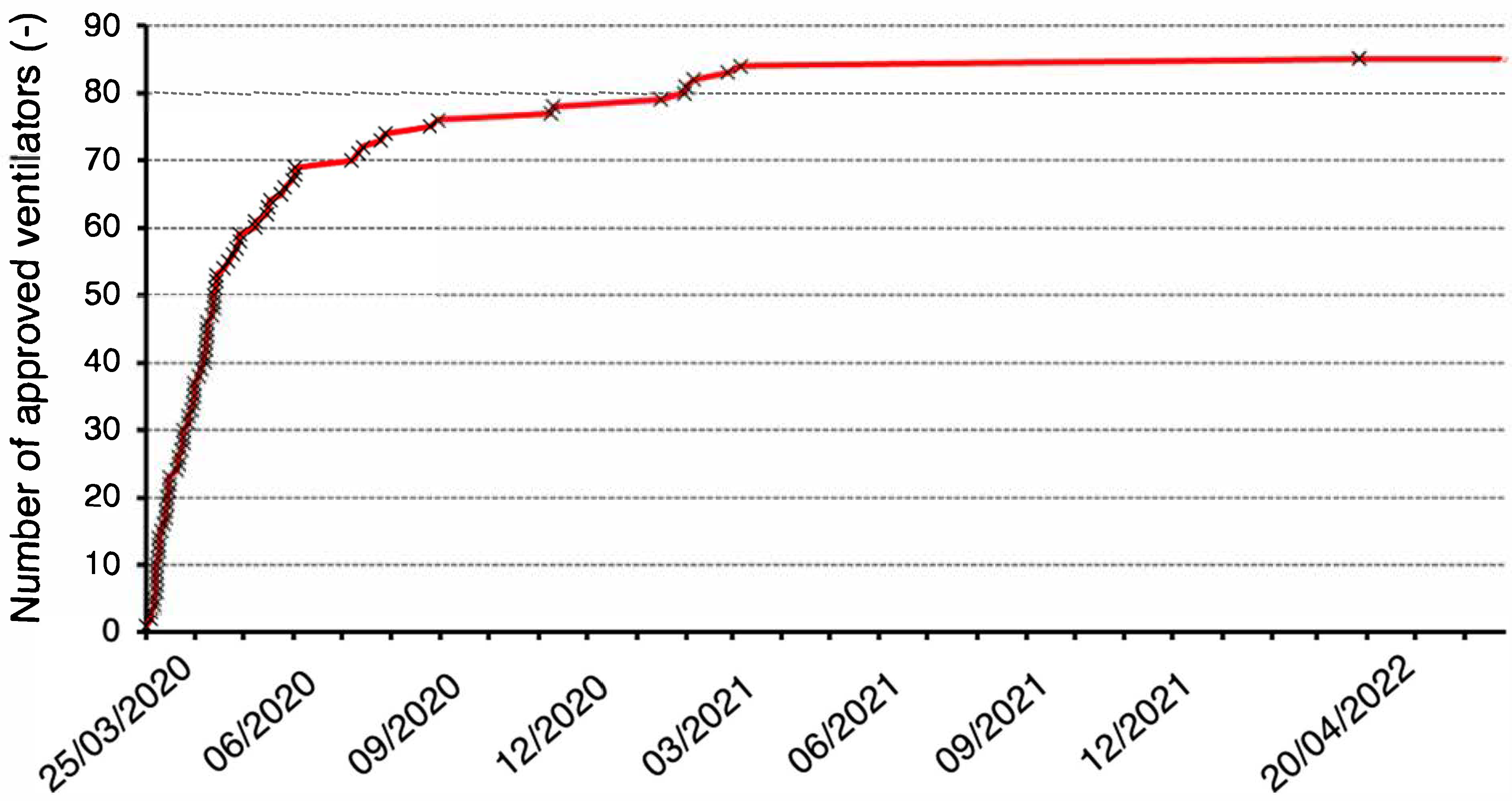
Out of hundreds of teams of experts and enthusiasts, only a few dozen succeeded in designing a ventilator that at least met the minimum safety and efficacy requirements of the U.S. Food and Drug Administration (FDA), World Health Organization (WHO), or UK Medicines and Healthcare products Regulatory Agency (MHRA) [
16,
17,
18]. Eighty-five ventilators gradually received Emergency Use Authorization (EUA) from the FDA [
16], with the time evolution of the number of approved ventilators shown in
Figure 1. A significant number of these devices were previously developed ventilators used in clinical practice with only minor modifications to software, hardware, or documentation. Eleven of the eighty-five devices were only approved as emergency resuscitators. Less than ten Emergency Lung Ventilators, which were newly designed and manufactured during the COVID-19 pandemic, received EUA. Examples include the Milano mechanical ventilator [
19], authorized on 1 May 2020, or the O2U ventilator Model 100 [
20], authorized on 22 March 2021.
One of these ventilators was also the CoroVent (MICo Medical s.r.o., Trebic, Czech Republic), authorized on 21 August 2020. The CoroVent ventilators were distributed to 27 Czech hospitals for free during the COVID-19 pandemics, but the production was stopped in 2021 when the Czech Republic had handled the crisis and the shortage of ventilators.
The aim of this study was to describe the CoroVent ventilator and to demonstrate that even such a simple ventilator in principle that is easy to manufacture can meet the requirements for accuracy and safety according to international standards and clinical demands.
2. Materials and Methods
The ventilator has been designed with a focus on the clinical needs of patients with respiratory insufficiency or failure due to COVID-19, particularly those with acute respiratory distress syndrome (ARDS). The number of ventilation modes and features implemented has been minimized to essential functions, simplifying the design while supporting effective gas exchange for the patient. For these reasons, our design focused on the development of a single mode of mandatory ventilation without the support of assisted modes of ventilation synchronized with the patient’s respiratory effort. The ventilator has been engineered to adhere to the principles of protective lung ventilation [
21], minimizing the risk of further lung damage during use. Although simplified in design, the ventilator is equipped with a robust electronic control system, safety mechanisms, and precise monitoring features to ensure reliable operation in critical care settings, to meet reasonable risk levels, and to comply with relevant safety standards, including international standards [
22,
23,
24,
25].
Testing protocols were developed to document compliance with international standards and MHRA requirements [
18]. The laboratory testing was conducted on ventilators produced during the COVID-19 pandemic, using specialized equipment for testing mechanical ventilators as described below.
2.1. Design Overview
The ventilator provides volume-controlled pressure-limited mandatory mechanical ventilation with the following adjustable parameters and their guaranteed ranges: tidal volume (VT) 200–800 mL, respiratory rate (RR) 5–45 breaths per minute, inspiratory-to-expiratory time ratio (I:E) 1:1–1:4, fraction of oxygen in inspiratory gas (FiO2) 21–100%, positive end-expiratory pressure (PEEP) 0–30 cmH2O, and peak inspiratory pressure reached during inspiratory phase (Pmax) 15–45 cmH2O.
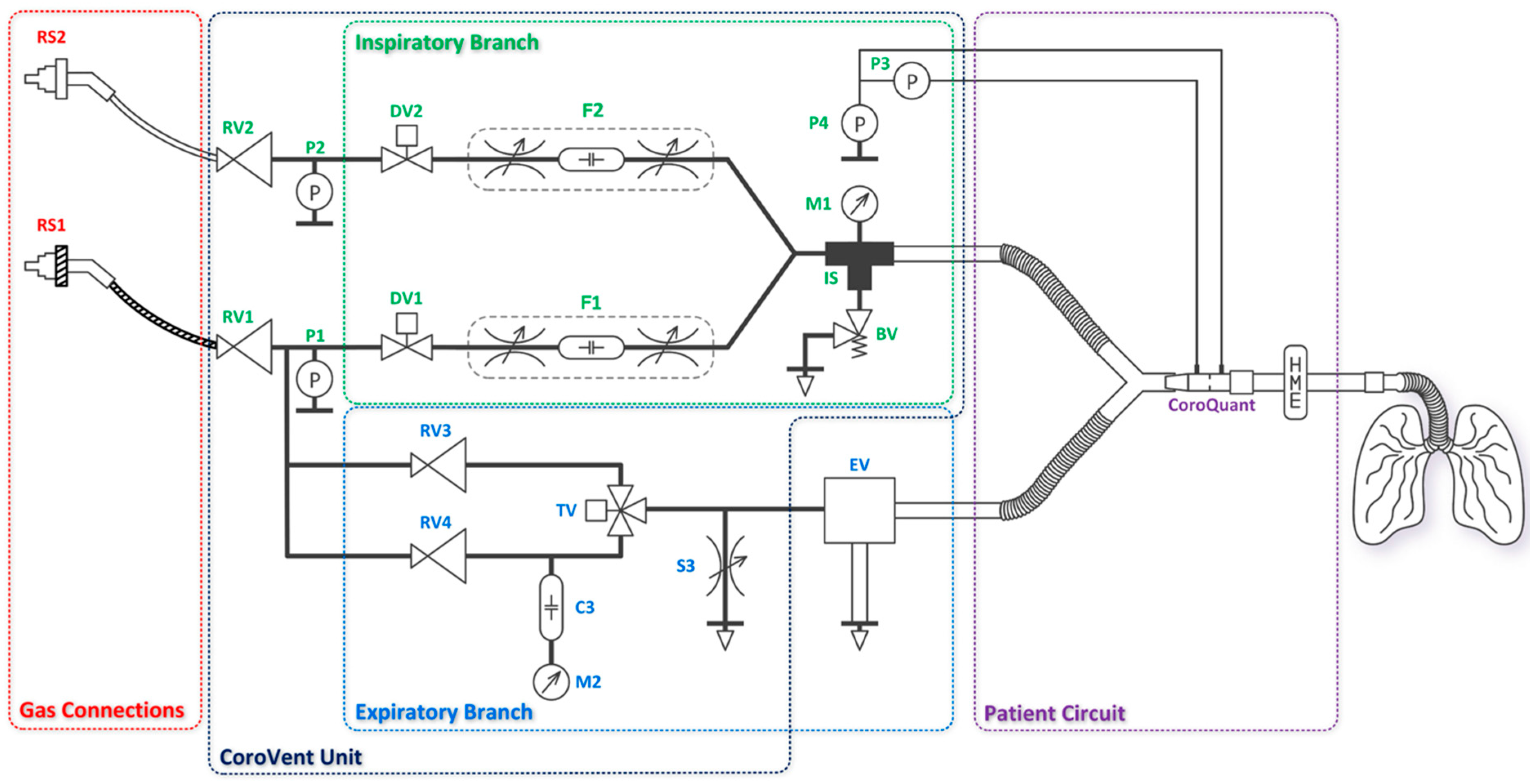
The ventilator consists of the CoroVent unit, gas connections, an expiratory valve, and a patient circuit equipped with a pneumotachograph flow sensor CoroQuant [
26]. The CoroVent unit includes an inspiratory branch, an expiratory branch, and pressure regulators with air and oxygen pressure sensors, as shown in the diagram in
Figure 2. Removable and disposable accessories, such as the expiratory valve and CoroQuant, were specifically designed to ensure proper and safe operation. A standard patient circuit with a heat and moisture exchanger and filter was recommended for optimal functionality.
2.1.1. Inspiratory Branch
The gas connections (RS1, RS2) are used to connect the ventilator to the hospital’s compressed air and oxygen supply, which typically operates at 4–5 bar. If CoroVent is used with gas cylinders, a standard medical pressure regulator must be installed on the cylinder. The air supply begins with a medical quick connector attached to a hose, which delivers air to the ventilator. The oxygen supply follows the same principle, using a dedicated oxygen quick connector. All materials in the oxygen circuit are oxygen-compatible. Inside the ventilator, the supply hoses are connected to pressure regulators (RV1, RV2), which reduce the hospital pipeline pressure to the ventilator’s operating pressure of 200 ± 2 kPa at a flow rate of 50 L min−1 for both air and oxygen.
After the pressure regulators, sensors (P1, P2) are placed in both branches to monitor the operating pressure. Based on the sensor data, the following alarms are provided: low air or oxygen pressure, large difference between the operating pressures of the two gases, and malfunction of one or both ON/OFF valves.
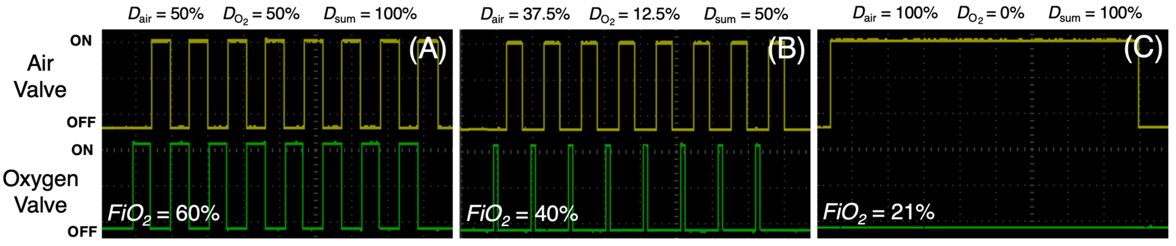
Inspiratory flow generation is then provided by two fast ON/OFF valves (DV1, DV2) connected directly after the pressure regulators. Both ON/OFF valves use pulse width modulation (PWM) with constant switching frequency of 10 Hz. By setting the duty cycle (
D) and the ON/OFF ratio of the air and oxygen valves, it is possible to generate the desired inspiratory flow rate while controlling the oxygen fraction in the ventilatory gas mixture, as depicted in
Figure 3A–C. The sum of the ON/OFF valve duty cycles (
Dsum) must not exceed 100% so that
FiO2 can be set over the entire range from 21% to 100% even at maximum flow. In this ventilator, a constant inspiratory flow was selected. With proper timing, the ON/OFF valves also control the respiratory rate and the inspiratory-to-expiratory time ratio and generate the inspiratory hold.
As shown in
Figure 4A, a series of short electrical pulses at the ON/OFF valve with
D = 50% creates high pressure oscillations forming an inspiratory flow. Acoustic filters (F1, F2) are then used to reduce these oscillations caused by the opening and closing of the ON/OFF valves. As shown in
Figure 2, each acoustic filter consists of two throttle valves and a compliance between them [
28]. The result is a smoothed pressure waveform behind the acoustic filter (
Figure 4B).
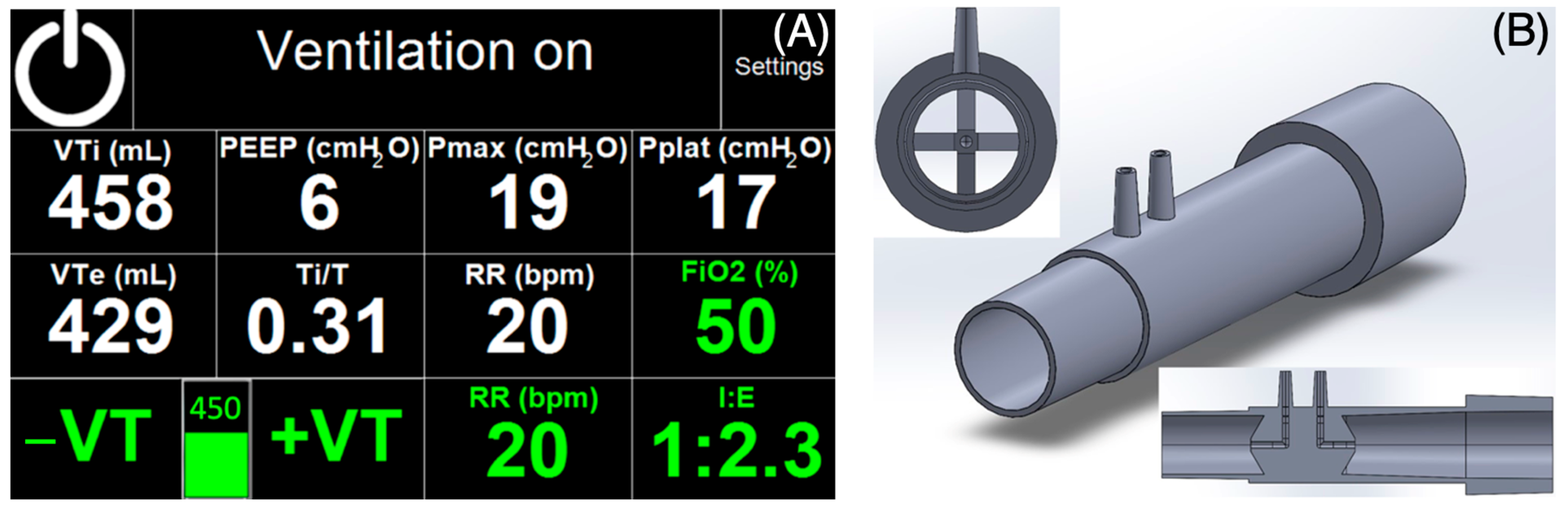
The air and oxygen branches are then joined (IS) and interconnected to a port for connection of the patient circuit. The IS coupling also interconnects these pneumatic circuits with a safety relief valve (BV) which is used to protect the patient from airway pressures exceeding 6 kPa (approximately 60 cmH
2O) according to ISO standard [
22]. The drawing of the safety relief valve design and its cross-section are shown in
Figure 5A. An analog pressure gauge M1 indicates the pressure at the inlet to the patient circuit, but the precise
Paw pressure is displayed on the ventilator screen and measured by the CoroQuant. The M1 pressure gauge provides the ventilator operator with information about the pressure throughout the entire respiratory cycle and is only an additional modality.
2.1.2. Expiratory Branch
The expiratory valve acts as a pneumatically controlled pressure-relief valve, limiting maximum inspiratory pressure (
Plim) during inspiration and regulating positive end-expiratory pressure (
PEEP) during expiration. The expiratory valve is designed so that the piston area on the control pressure side is ten times smaller than the diaphragm area on the patient circuit side. This 10:1 ratio ensures that the expiratory valve generates a pressure 10 times lower than the control pressure, allowing the system to operate at higher control pressures and therefore higher precision due to the wider setting range of the pressure regulator. The drawing and cross-section of the expiratory valve are shown in
Figure 5B.
Using a three-way valve, the expiratory valve is alternately supplied with two different pressures generated by the RV3 and RV4 pressure regulators. The three-way valve switches electronically between inspiratory and expiratory phases. Both pressure regulators receive an internal operating pressure of 200 ± 2 kPa, reduced from the hospital pipeline pressure. The user can adjust Plim and PEEP using two control knobs on the front panel of the ventilator. PEEP is controlled by adjusting RV3 and Plim is controlled by RV4. A compliance (C3) filters out short-term pressure drops from RV4, allowing the ventilator operator to easily set the Plim pressure based on the pressure measured by the analog pressure gauge (M2). In addition, to ensure proper operation of the expiratory valve, a bleed valve (S3) is added to the circuit to quickly depressurize the system when the three-way valve changes from inspiration to expiration (from higher to lower pressure).
2.2. Control System, Safety, and Monitoring of the Ventilator
The ventilator operates using a programmable logic controller (PLC) CP6606 (Beckhoff, Verl, Germany) powered by an ARM Cortex™-A8 processor running real-time operating system Windows Embedded Compact 7 (Microsoft Corporation, Redmont, WA, USA). The ventilator control firmware was developed within the TwinCAT 3.1 programming environment (version 3.1, Beckhoff, Verl, Germany), utilizing Microsoft Visual Studio as the integrated development interface. The firmware architecture incorporates two independent threads: a primary thread, designated as high-priority, responsible for managing inspiratory and expiratory valves, processing sensor data, and evaluating alarm conditions; and a secondary thread, operating at a lower priority, which serves as the graphical user interface and facilitates bidirectional communication between the primary thread and the user. The graphical user interface displays measured parameters and active alarms and provides functionality for user parameter adjustment and ventilator operation.
The respiratory phases are hard-controlled. Ventilation is managed without sensor feedback. This means that all phases are rigidly timed according to the current CoroVent settings, as determined by the respiratory therapist. Any adjustment to the respiratory settings initiates a recalculation of timings of all valves. Sensor data are currently limited to providing ventilation information to the respiratory therapist and managing alarms as the ventilator does not support synchronized ventilation modes.
During ventilation, inspiratory and expiratory tidal volumes (
VTi and
VTe),
PEEP, peak inspiratory pressure reached during inspiratory phase (
Pmax), plateau pressure (
Pplat), the ratio of inspiratory phase duration to the total time of the respiratory cycle (
Ti/
T), and
RR are displayed. Ventilation parameters are set using a touchscreen (glove compatible) and two rotary knobs on the front panel: one for
PEEP and the other for
Plim. All parameters shown in green in
Figure 6A are parameters set by the user. All parameters marked in white on the touchscreen are parameters measured by a specially designed pneumotachograph flow sensor CoroQuant [
26]. The volume and pressure measured by CoroQuant at the airway opening are sensed by a differential pressure sensor (MPXV7002, NXP, Einthoven, The Netherlands) and an absolute pressure sensor (MPXV4006DP, NXP, Einthoven, The Netherlands).
The ventilator includes a basic alarm system per ISO 80601-2-12 [
22] and EN ISO 60601-1-8 [
23], with audible and visual signals. A single alarm level is implemented. In addition, the ventilator, its touchscreen, labels, and software use established respiratory care terminology.
Distinct from many emergency ventilators developed during the COVID-19 pandemic, the CoroVent incorporates the full suite of safety features and functionalities expected of a standard Intensive Care Unit (ICU) ventilator. These features have been independently verified by the Electrotechnical Testing Institute in the Czech Republic (test report no. 020857-01/01, issued 21 April 2020), confirming its compliance with essential performance standards. Testing included assessments of mechanical resistance and safety, electromagnetic compatibility, and protection from water, all within the requirements for medical device use and within scope of ingress protection of IP21.
Four key safety principles protect against excessive airway pressure. These protective measures are arranged in order of detection and the severity of any unwanted pressure increase in the patient’s circuit. Software-based features include a user-adjustable maximum pressure alarm threshold that can be set up to 45 cmH2O and an automatic response that initiates expiration and triggers an alarm if pressure exceeds 55 cmH2O for 150 ms or longer. The hardware protections provide an extra layer of safety. The user can manually set the maximum achievable pressure during ventilation (Plim) between 15 and 45 cmH2O, and a safety relief valve serves as the final safety mechanism if all else fails.
The patient’s airway pressure is measured by two independent systems. An electronic system is connected to the PLC controlling the ventilator and to an analog manometer located on the front panel of the device. Two sensors measure the inlet oxygen and air pressures and allow the ventilator to respond with an alarm condition to a gas delivery problem. Power protection is provided by a capacitive UPS (UBC10.241, PULS, Munich, Germany) to safely bridge possible short-term power failures for a minimum of 30 min.
2.3. Testing
The ventilator was subjected to a series of laboratory tests similar to the studies by Knorr et al. [
29] or Rebelo et al. [
30], based mainly on the requirements of the FDA EUA [
16], MHRA [
18], and ISO 80601-2-12 [
22]. The testing methodology was based on standardized, reproducible lung models composed of a thermocompensated rigid test lung and resistive elements. These simplified representations of the respiratory system were deemed sufficient to verify the ventilator’s functionality and safety in accordance with the applicable regulatory requirements. In this article, we focused on the most clinically relevant ones, such as performance stability test, volume accuracy, volume monitoring, pressure safety limitation, or
PEEP stability. A picture of the ventilators during the testing is provided in
Supplementary Materials Figure S1.
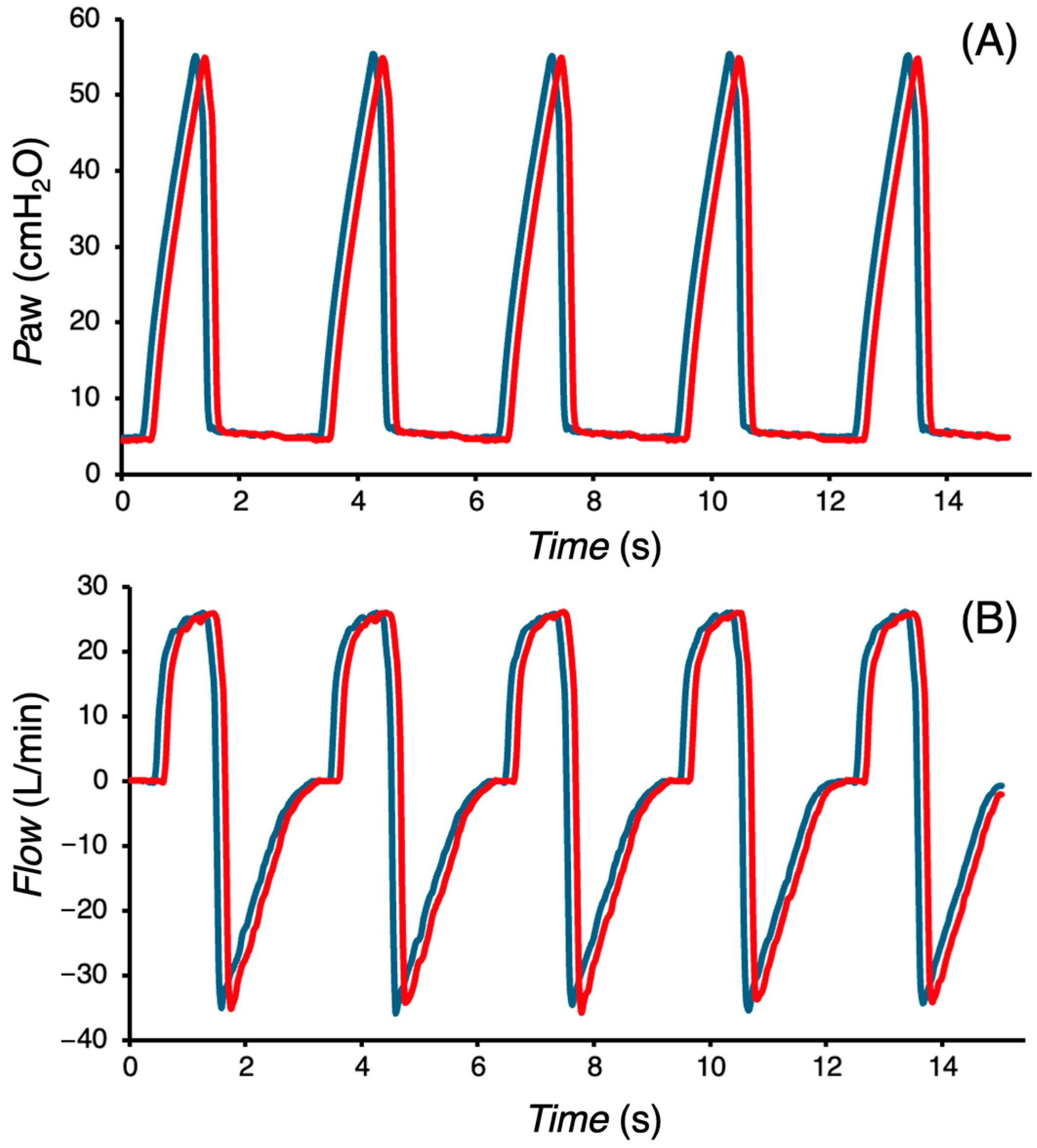
First, we tested the performance stability of the ventilation for 24 h under unfavorable conditions (combination of low compliance and high flow resistance of the test lung). The compliance of the thermocompensated test lung was set to 10 mL cmH2O−1 and the linear resistance to 50 cmH2O s L−1. Ventilation was set to VT = 375 mL (maximum adjustable VT without alarm triggering expiration), PEEP = 5 cmH2O, RR = 20 min−1, and I:E = 1:2. Paw and Flow waveforms and delivered tidal volume were recorded with the Fluke Biomedical VT900A gas flow analyzer (Fluke Biomedical LLC, Everett, WA, USA) at the beginning and end of the test period. Additionally, a battery runtime test was performed for the same setting.
Next, the accuracy of tidal volumes delivered by the ventilator,
PEEP stability, and volume monitoring were tested. Ventilation was set to
PEEP = 5 cmH
2O,
RR = 20 min
−1, and
I:E = 1:2. The thermocompensated test lung was set to a compliance of 40 mL cmH
2O
−1 and a linear resistance to 5 cmH
2O s L
−1. Nine different
FiO2 settings were used for four
VT settings ranging from 225 to 675 mL, covering the representative volume range of the ventilator. Each of the 36 different settings lasted 30 s (11 breaths). Reference tidal volumes were calculated based on the experimentally measured compliance of the lung model (40.0 ± 0.1 mL cmH
2O
−1), according to the ISO standard [
31]:
where
VT is the calculated inspiratory tidal volume,
C is the compliance of the test lung,
PEEP is the positive end-expiratory pressure and
Pmax is the peak inspiratory pressure. The difference between
PEEP and
Pmax was measured by the VT900A gas flow analyzer.
A scatter plot was constructed to assess the relationship between the reference
VT and the set
VT. The data were fitted with a linear regression line using the least squares method, and the corresponding function was determined. Additionally, the limits required by the ISO standard [
22] were included in the plot.
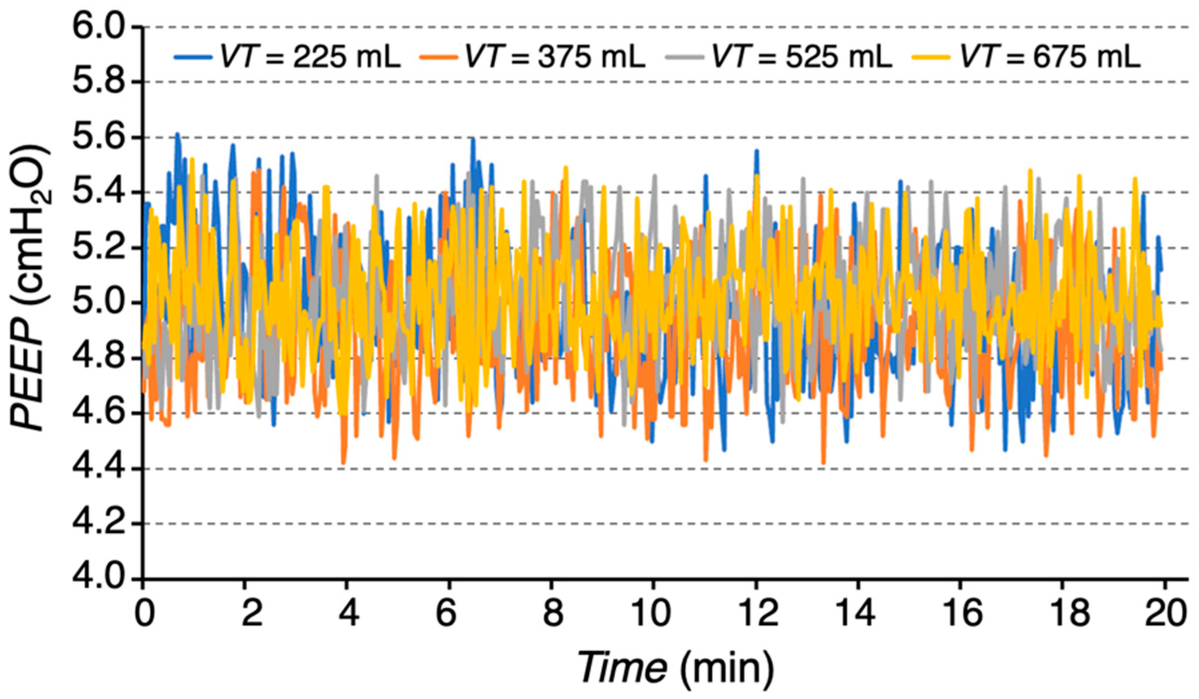
For each tidal volume setting and variable FiO2, a corresponding value of PEEP was recorded over a 20 min period and a graph of PEEP variation over time was generated. Means and standard deviations (SDs) were calculated for each tidal volume setting.
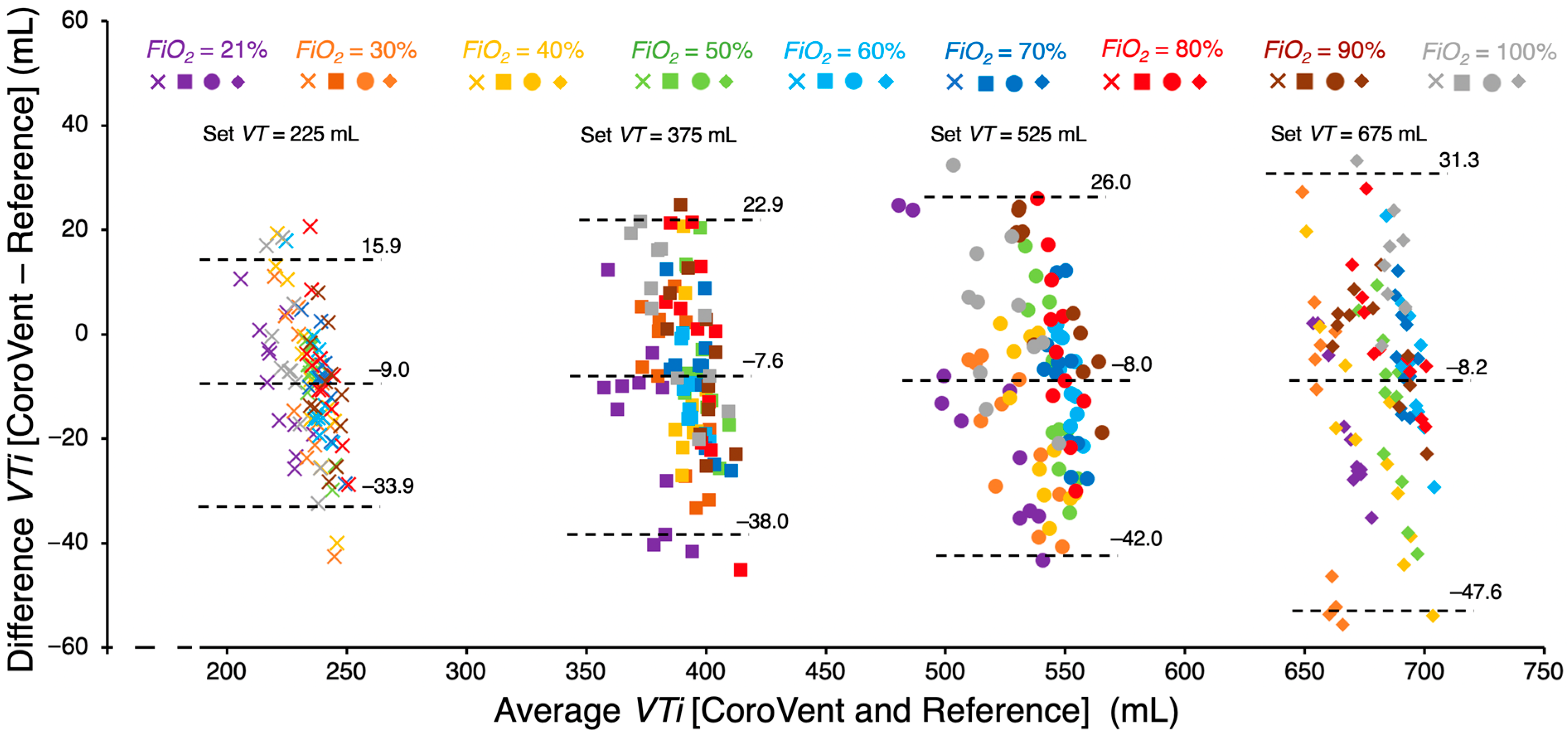
To assess the accuracy of tidal volume monitoring of the CoroVent ventilator, VT measured by the CoroQuant was compared with reference VT obtained by the VT900A gas flow analyzer. Agreement between CoroVent and the reference was evaluated using Bland–Altman analysis, a standard method for assessing bias and scatter between two different measurement techniques. The 95% limits of agreement were determined by adding and subtracting 1.96 standard deviations from the mean bias, providing an estimate of the expected differences between simultaneously measured tidal volumes.
Finally, the pressure limitation (Plim) achieved by the preset inspiratory pressure limit on the expiratory valve was assessed using a test lung with a compliance of 20 mL cmH2O−1 and a resistance of 5 cmH2O s L−1. Ventilator settings were initially configured to RR = 20 min−1, I:E = 1:2, FiO2 = 60%, VT = 375 mL, and PEEP = 0 cmH2O. The Plim was set to 30 cmH2O. PEEP was then repeatedly manually increased in increments of 2 cmH2O, ranging from 0 to 20 cmH2O. Paw, minute ventilation (MV), and VT were measured using the VT900A gas flow analyzer. Paw and its pressure limitation throughout the entire respiratory cycle were recorded for each PEEP adjustment, along with the corresponding MV and VT values.
3. Results
The presented
Paw and
Flow waveforms (
Figure 7) indicate no change in the performance of the CoroVent ventilator after 24 h of continuous ventilation under unfavorable conditions. The mean measured
VTi at the beginning of the 24 h test period was 380.8 ± 5.6 mL, and at the end of the test period, it was 382.0 ± 4.1 mL, demonstrating consistent ventilator performance over time. In a separate battery runtime test, the ventilator operated for 126 ± 8 min.
The measured
VTi by independent reference demonstrates a strong correlation with the set
VT, exhibiting near-perfect trendline dependence (
Figure 8). Furthermore, all measured
VTi values fall within the required accuracy defined by the ISO standard [
22].
Figure 9 indicates an excellent stability of
PEEP across different
VT settings over the 20 min period. The measured
PEEP values were as follows: 4.96 ± 0.25 cmH
2O for
VT = 225 mL, 4.90 ± 0.24 cmH
2O for
VT = 375 mL, 5.01 ± 0.21 cmH
2O for
VT = 525 mL, and 5.04 ± 0.21 cmH
2O for
VT = 675 mL (mean ± SD).
A comparison of measured
VTi values between the CoroQuant of the CoroVent ventilator and the independent reference V900A gas flow analyzer is presented in
Figure 10. The results indicate that CoroVent consistently measured
VTi 7.6–9.0 mL lower than the reference, depending on the set
VT. Additionally, as the
VT increases, the variability in
VTi differences also increased. Lower average
VTi values were observed at a preset
FiO2 of 21% across all
VT settings.
Figure 11 illustrates the effect of increasing
PEEP on
Paw,
MV, and
VTi when the
Plim was set to 30 cmH
2O. As shown in
Figure 11A, inspiratory pressure started to be limited as
PEEP was gradually increased during respiratory cycles. The corresponding reductions in
MV and
VTi, dependent on the
PEEP setting, are presented in
Figure 11B,C. Under the given ventilation setting and test lung configuration, pressure limitation became evident at
PEEP ≥ 10 cmH
2O. When
PEEP was increased to 20 cmH
2O,
MV decreased from 7.5 L/min to 4 L/min.
4. Discussion
The results of our testing showed that the CoroVent ventilator provides stable, safe, and accurate ventilatory support. A key advantage of CoroVent is its simple design, which facilitates rapid production while maintaining essential features for patient safety. Given the specific COVID-19 progression associated with induced ARDS and urgent development timeline, a single ventilation mode suitable for this etiology was selected. By focusing on volume-controlled, pressure-limited mandatory ventilation, the design minimizes complexity without compromising clinical efficacy. The ventilator incorporates multiple layers of safety, including software-controlled pressure limits, hardware-adjustable maximum pressure settings, and a mechanical safety relief valve, all of which act as protective barriers to minimize ventilator-induced lung injury.
The performance stability test showed no significant deviation in
Paw and
Flow waveforms and
VTi over a 24 h period, even under unfavorable conditions. This indicates that the ventilator maintains consistent function over extended use. The ability to operate for over two hours on battery power, well above the ISO-required minimum of 30 min [
22], demonstrates robust performance under power failure conditions, which is critical for clinical readiness in emergency and mobile settings. This aligns with the importance of incorporating reliable control strategies to address potential operational failures in emergency biomedical systems [
32]. High accuracy of
VT delivery when compared to an independent reference suggests that the ventilator can support effective gas exchange while minimizing the risks associated with hypoventilation or hyperventilation. Additionally,
PEEP stability was maintained across different
VT settings, further validating the reliability of the system in providing consistent
PEEP to prevent alveolar collapse and improve oxygenation. The CoroQuant pneumotachograph flow sensor, specifically designed for CoroVent, with its processing algorithm and electronics, demonstrated accurate monitoring of
VTi within acceptable limits when compared to the reference measurements. Accurate monitoring is essential for safe and effective mechanical ventilation, allowing clinicians to adjust settings based on real-time patient needs.
Some of the inspiratory branch characteristics, such as the dependence of measured
FiO2 on set
FiO2, the relationship between measured
VTi and set
FiO2, and the interaction between delivered
VTi and maximum pressure relative to respiratory system compliance and resistance were tested previously during the design of the inspiratory flow generation [
28].
The shortage of commonly available flow sensors during the COVID-19 pandemic led to the decision to design a custom flow sensor, CoroQuant. The initial design and optimization of the CoroQuant was carried out using computational fluid dynamics (CFD) simulation in COMSOL Multiphysics (version 5.4.0.225, COMSOL, Inc., Burlington, MA, USA). The first sensor prototypes were manufactured and tested using 3D printing technology. During the optimization, several positions and shapes of the resistance element within the sensor body were tested to improve the performance of the sensor. This process included testing using common CFD simulation methods [
33,
34,
35]. The final sensor design was chosen based on extensive experimentation with various resistance element shapes and configurations. A metal mold was then created for plastic injection molding, ensuring reproducible and consistent sensor properties. The design and measurement results were described in the study by Bís et al. [
26]. In designing the CoroQuant flow sensor, emphasis was placed on ensuring that the resulting design would not cause an excessive increase in dead space. The final flow sensor’s dead space is comparable to that of flow sensors used in respiratory care, such as the D-Lite (GE Healthcare, Chicago, IL, USA).
The CoroVent ventilator uses CoroQuant to measure flow based on the commonly used differential pressure measurement. However, the internal resistance element of the CoroQuant sensor has a unique shape, resulting in distinct pressure–flow characteristics. To ensure future compatibility with commercial flow sensors, such as the D-Lite (GE Healthcare, Chicago, IL, USA), the ventilator’s software allows modification of the “slope” and “exp” coefficients via the service menu. These parameters define the bidirectional pressure–flow characteristics and enable adjustment of the flow calculation algorithm based on the measured pressure difference.
The simplicity of the ventilator design is underlined by the unique solution of generating inspiratory flow and gas mixing by two fast electronically controlled ON/OFF valves. Standard ICU ventilators typically use proportional valves with mixing chambers or turbines with feedback control to generate inspiratory flow. However, the testing and design of such ventilators is time consuming and often requires specially designed medical components which were not commercially available during the COVID-19 pandemic situation. An important advantage of this unique solution is also its easily adaptable scalability. The fast ON/OFF valves are controlled by a digital (PWM) signal, providing a simple yet highly flexible control method. This design allows the ventilator to easily adapt to different patient populations, ranging from neonates to adults and large animals in veterinary care, by simply replacing the ON/OFF valves with models suited to the required flow rates. The core control algorithm does not need to be changed.
Sterilization and biocompatibility were also considered, particularly for components directly exposed to the gas mixture entering the patient’s airways. The expiratory valve and CoroQuant were sterilized before use, and all relevant components were manufactured using biocompatible materials, ensuring patient safety.
The simple design required the omission of certain standard features available in advanced ICU ventilators, such as patient-triggered ventilation, real-time oxygen concentration monitoring, sophisticated ventilation modes, or integrated waveform analysis. However, in line with the initial design plan, CoroVent was only intended to increase the potential capacity of ventilator-dependent patients, not to fully replace standard ICU ventilators. Once the patient’s condition improved to the point where they could breathe spontaneously, they were transitioned to another ventilator to allow for weaning. In the case of FiO2 monitoring, the inspiratory branch design assured precisely controlled gas mixing, making additional measurement unnecessary. If there was a risk of incorrect oxygen delivery in the ventilation mixture, the alarm was triggered by a malfunction of one of the ON/OFF valves. In addition, the device relied on a hospital air and oxygen supply, which was not always readily available in all settings, particularly low-resource settings or field hospitals. Future iterations could explore the implementation of additional functionalities; however, some of these would highly complicate the possible rapid mass production.
Despite these limitations, the CoroVent ventilator provided an effective and reliable solution for emergency scenarios. The successful use of CoroVent ventilators in Czech hospitals during the COVID-19 pandemic demonstrated the practical utility of such devices in mitigating ventilator shortages. In addition, the results of this study support the potential for simple yet effective ventilator designs to play a critical role in crisis response.


