1. Introduction
The chemical, refrigeration, power, and nuclear industries, among others, extensively utilize heat transfer systems. Thermohydraulic performance of heat exchanger tubes, as a fundamental component in heat transfer systems, directly influences system efficiency [
1,
2]. The global energy consumption in industries is expected to increase by 40% by the year 2040 [
3]. Augmenting heat thermal performance has become a crucial strategy for reducing energy consumption and operating costs. Increasingly, researchers are investigating active and passive approaches to improve heat transfer and enhance thermal performance. Among the heat transfer enhancements, those that utilize inserted devices have significantly enhanced the performance of conventional heat exchangers. Researchers frequently employ twisted tapes to improve the performance of heat exchange tubes because of their reliability, uncomplicated design, and ease of installation. The use of twisted tapes has two opposing effects: a disadvantageous pressure drop and an advantageous heat transfer augmentation [
4,
5]. These phenomena are caused by (1) intensification of turbulence and disruption of the boundary layer region, (2) an enlarged heat transfer region, and (3) creation of swirling flows [
6,
7,
8].
Researchers have systematically optimized heat exchangers with twisted tape insert augmentation through three-dimensional parametric studies. These include modifying tape geometry (e.g., twist ratio, edge curvature), configuration or multiple tape configurations (e.g., co/counter-swirl arrangements), and working fluid selection (e.g., nanofluids, phase-change slurries). Chammam et al. [
2] examined the thermohydraulic performance behaviors of AIN-Al
2O
3/water hybrid nanofluids with twisted tapes mounted in a tube. Twisted tapes with various twist pitches were selected. The Reynolds numbers ranged from 800 to 2000. They used a twisted tape with a pitch ratio of 2.0 and a hybrid nanofluid with a 0.04 volume fraction. In these experiments, the hybrid nanofluid performed excellently in terms of Nusselt number, heat transfer coefficient, and friction factor. Moreover, as the Reynolds number increases, axial convection becomes greater, optimizing heat transfer, disturbing the boundary layer, and thereby enhancing heat transfer from the wall to the fluid. Eiamsa-ard et al. [
6] examined the performance of tubes with a full-length single twisted tape, full-length double-tapes, and double-spaced tapes with varying twist and space ratios (space length-to-tube diameter). Their research illustrated that double-tapes and/or double-spaced tapes with a smaller space ratio (0.75) perform the greatest heat transfer performance. This was due to more complex swirl flow and greater fluid mixing, which augmented heat transfer. Harish and Manjunath [
7] evaluated the fluid dynamics and thermohydraulic performance of a tube with twisted tapes employing circular protuberances (CPTTs). The twist ratio was fixed, and tapes were installed in an isothermal tube. They indicated that a twisted tape with circular protuberances provided a 1.5 times greater thermal augmentation factor than a typical twisted tape (TT). Its Nusselt number and friction factor were 15–24% and 12–22% higher than those of a TT, respectively. Dandoutiya and Kumar [
8] conducted a numerical study on double-pipe thermal exchangers utilizing W-cut twisted tapes to improve heat transfer performance. W-cut twisted tapes with 0.2–0.6 depth-to-width ratios were tested. These results observed that the vortices produced by the twisted tapes enhanced heat transfer, and increasing the cutting depth intensified turbulence and improved fluid mixing. The thermal performance factor increased with cutting depth, reaching its maximum value of 1.5. The W-shaped cut twisted tape exhibited a superior performance at high Reynolds numbers.
Altun et al. [
9] investigated heat transfer enhancement in a tube by twisted trapezoidal and trapezoidal tapes. Their results showed that under an isothermal condition with Reynolds numbers ranging from 5000 to 25,000, the twisted trapezoidal tapes improved not only thermal transfer but also increased pressure losses. Twisted trapezoidal tapes showed an overall performance factor greater than unity. The highest Nusselt number, 118, and overall performance factor, 1.16, were obtained by employing twisted trapezoidal tapes with a thread height of a quarter of the tape’s width and an 80° twisted pitch length that was 4.0 times the inner diameter. Their results indicated that twisted trapezoidal tapes combined the advantages of twisting and trapezoidal shapes performed well in turbulent heat transfer. Zheng et al. [
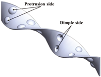
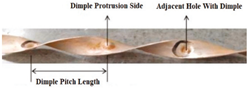
10] carried out the effect of twisted tapes with dimples on heat transfer, demonstrating both considerably improved thermal transfer with a moderately increased pressure drop. The dimpled tape had better performance on the dimpled and protrusion sides compared to a typical twisting tape. The heat transfer was improved with a smaller twist ratio and deeper dimples. The highest thermal performance was achieved with a 3.0 twist ratio and a 0.3 dimple depth to tube diameter ratio. Turbulence intensity in the depressions was markedly increased, particularly at the tube wall and in the core region, potentially resulting in intensified secondary flows and thus enhanced heat transfer. Heeraman et al. [
11] performed the thermal and frictional behaviors of water flowing through a dual-pipe heat exchanger installed with twisted tapes. They are tested with various dimple ratios, maintaining a 5.5 twist ratio. They revealed that the heat transfer increased with the Reynolds number, while the best configuration for a higher heat transfer rate was at a
D/
H of 3.0 among different diameters. The friction factor was lowest when the diameter-to-depth ratio was 4.5. Considering the heat transfer and pressure drop behaviors, the combination of
D = 4.0 mm and
D/
H = 4.5 yields the best performance.
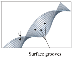
In their study [
12], Fetuga et al. examined how surface-grooved twisted tapes, toroidal rings, and stents affected the heat transfer behavior. Their results indicated a positive correlation between thickness and width ratios with two metrics, the heat transfer enhancement and the pressure loss. Nevertheless, thermal performance decreases due to increased pitch ratios. When the width-to-thickness ratio increased, the heat transfer and pressure loss significantly increased, and the thermal performance rose to 1.4. At a 0.68 width-to-thickness ratio, the Nusselt number was 105% higher than that of a smooth tube. At greater pitch ratios, both the heat transfer rate and pressure loss decreased, and thermal performance was greater as the pitch ratio decreased. Increased thickness led to greater heat transfer rate and pressure drops.
Abidi et al. [
13] revealed the thermohydraulic characteristics of a parabolic solar trough utilizing twisted tapes with circular holes filled with a water–copper oxide nanofluid in the turbulent zone. The hole diameter ratios were 0.5, 0.7, and 0.9. Their results indicated that the greatest heat transfer performance factor was achieved under the condition that the diameter-to-width ratio was 0.9, the nanoparticle volume fraction was 0.4%, and
Re = 10,000. The highest heat transfer performance was 64% greater than that of other modes. Kola et al. [
14] identified the optimal parameters to improve heat transfer while decreasing the friction coefficient in dual pipe heat exchangers having twisted tapes of variable cross-sectional cuts. Their findings indicated that the relationship between the cut radius and cut angle markedly affected heat transfer, 1965 W/m
2 K with a 0.077 friction coefficient, as a function of mass flow rate. The best performance coefficient was observed with a cut radius of 5.46 mm and a cut angle of 12°. Chang and Huang [
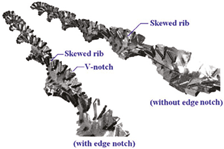
15] examined enhancements in heat transfer (HTE) utilizing twisted tapes with spiky ribs, with and without edge notches. They considered related increases in pressure drop and efficiency in heat convection. Their research examined distributions of heat transfer in tubular flows augmented with several types of twisted tapes with spiky ribs. The tape with a low twist ratio (1.56), having notches and installed in a forward condition, provided higher heat transfer and pressure drops. These results indicated that twisted tapes exhibited elevated levels of heat transfer with minimal pressure drop. Chang et al. [
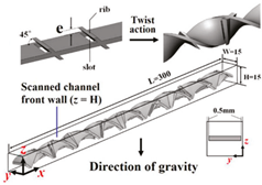
16] employed twisted tapes with conjugate inclined ribs to augment performance and reduce pressure loss. The ribs turned flow recirculation cells into solenoidal vortices, while the slots enabled the exchange of mass, momentum, and energy across axial swirls. These flow systems enhanced heat transfer and diminished the form drag generated by ribs. The observed thermal performance factor was 1.31 with a 45° rib inclination angle, twist ratio of 2.0, and a rib-pitch–rib height ratio of 11.2. The combined effect of the inclined ribs with the slots mostly explained the best thermal performance index since it broke the boundary layer, increased turbulence, and lowered the friction factor, thereby improving thermal performance. Sedaghat et al. [
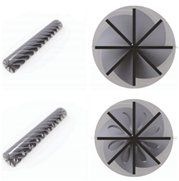
17] studied the influence of twisted tapes on thermohydraulic performance in a heat exchanger under laminar flow. Plain tubes, TT, and holed twisted tapes with varying W-ratios and blade numbers were examined. Their results showed a beneficial relationship between the blade numbers and two metrics, the Nusselt number and the pressure loss. The performance index decreased with greater blade numbers. A holed, twisted tape with six blades presented an optimal performance coefficient. Wang et al. [
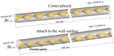
18] reported how the twisted tape’s location affected the fluid character and thermal enhancement in the tube. With a similar twist ratio, 2.0, tape widths were varied from 12–20 mm, and Reynolds numbers ranged from 2600–8760. Their research illustrated that a twisted tape placed against the wall had 3–18% higher heat transfer than a tape located at the core of the tube. Eiamsa-ard et al. [
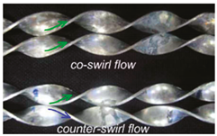
19] focused on the effects of co/counter-swirl flows on thermal augmentation. Their experiments covered dual-twisted tapes with twist ratios of 2.5–4.0. The results observed that the dual-counter-swirl tapes with a 2.5 twist ratio provided the greatest thermal performance, 1.39. Eiamsa-ard and Changcharoen [
20] studied the thermohydraulic properties of ducts into which dual and quadruple twisted-tapes were installed in various arrangements. The results were contrasted with the performance of smooth ducts and ducts with TTs. The thermohydraulic properties of ducts rely on the number of tapes and their configuration. The number of tapes was more significant. Heat transfer rate and pressure losses rose with increased numbers of tapes. The quadruple twisted tape provided better heat transfer than a dual twisted tape, but with a lower thermal performance factor. Maximal thermal performance was obtained by the configuration of diagonal double counter-tapes and diagonal double co-tapes.
The effects of twisted tape width with various arrangements on heat transfer performance were studied by Sheikholeslami et al. [
21]. Their results showed that tapes and nanofluids can significantly improve heat transfer efficiency and reduce energy losses. The performance of the thermal system was optimal, and the entropy generation was minimal at high Reynolds numbers and with multiple twisted tapes. At four twisted tapes and a 0.03% concentration of Al
2O
3 nanofluid, the maximum friction entropy of the system reached 1605. Chen et al. [
22] employed a two-phase simulation to analyze water/MWCNT nanofluid flow and thermohydraulic performance using a triple-perforated twisted-tape. A nanofluid was utilized as the working medium, and the Reynolds numbers ranged from 6000 to 24,000. Their study indicated that a triple-perforated tape significantly affected the channel heat transfer coefficient. The studied cases caused fluctuating flow and increased heat transfer efficiency and pressure loss. A triple-perforated tape having four complete waves with high-concentration MWCNT nanofluids (
φ = 0.8%) offered the best performance evaluation criterion, 1.92.
The results of heat transfer enhancement using modified twisted tapes with various surface designs are summarized in
Table 1. Among these, twisted tapes featuring uneven surfaces, such as dimpled tapes [
10] and inclined rib-slot tapes [
16], have demonstrated promising improvements in both heat transfer and thermal performance. Building on this concept, the present study employs V-ribs as the surface modification for twisted tapes. V-ribs were selected due to their advantages over both dimpled surfaces and inclined ribs, as highlighted in previous studies. Unlike dimples, which create localized turbulence [
23], V-ribs induce continuous boundary layer disruption along the flow path, resulting in more uniform heat transfer enhancement. Furthermore, V-shaped ribs generate vortices and give higher thermal performance than the typical orthogonal or angled ribs [
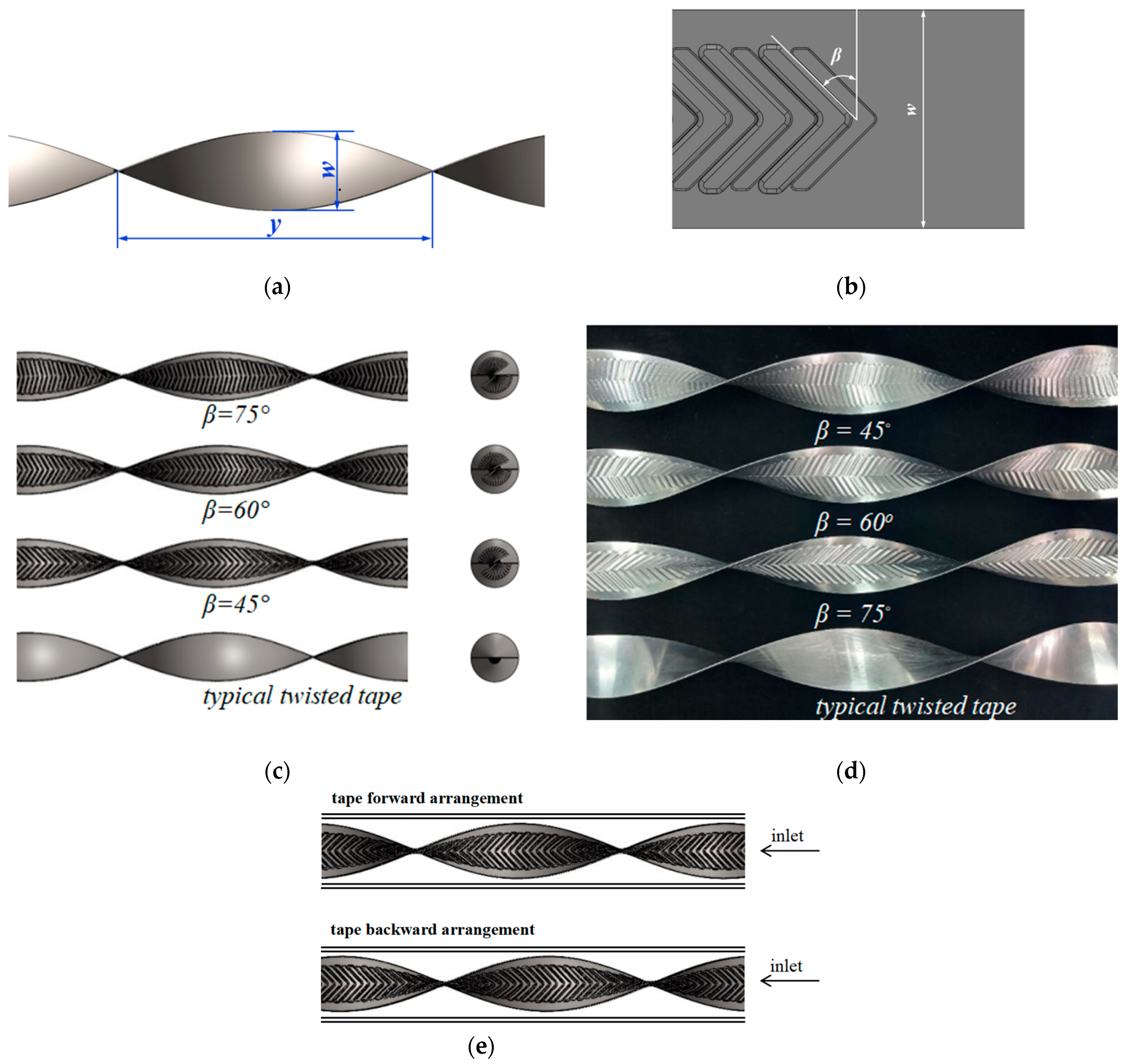
24]. In addition, the geometry of V-shaped ribs can be easily modified by adjusting their attack angle to optimize heat transfer performance. Based on these findings, this study focuses on twisted tapes with continuous V-ribs (CVRT). The investigation explores the effects of CVRT inserts, with protruding V-ribs, on heat transfer characteristics, pressure drop, and thermal performance in a heat exchanger. The heat transfer coefficient is evaluated for three V-rib attack angles (β): 15°, 30°, and 45°, considering both forward and backward tape orientations. Air is used as the working fluid within a Reynolds number range of 6000 to 20,000. All test cases are conducted under consistent rib extrusion depth and rib-to-edge distances.
3. Experimental Facility
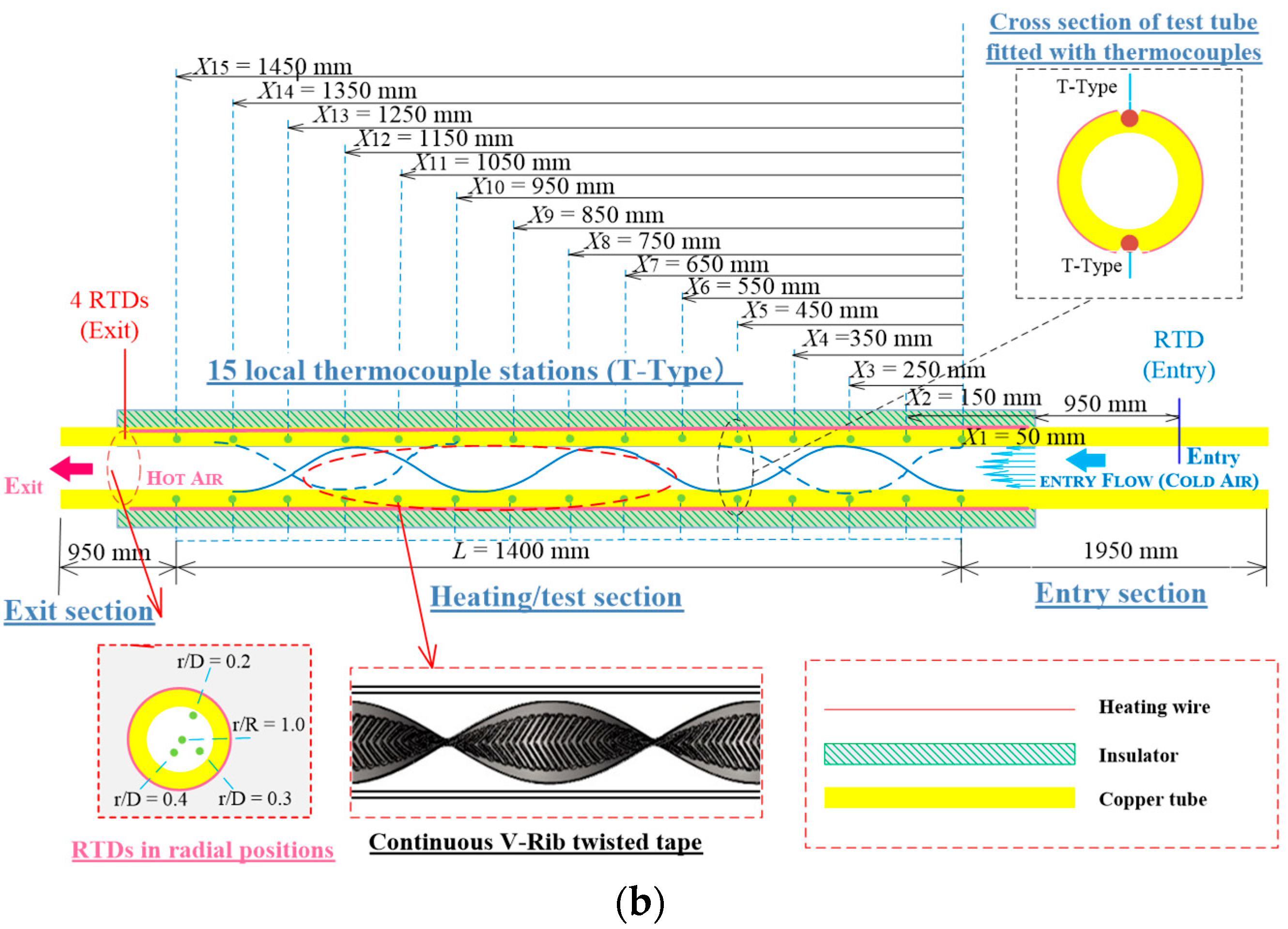
A detailed configuration of the experimental facility is displayed in
Figure 2a,b. The test configuration has four segments: the intake, pressure stabilization and temperature regulation, testing, and data measurement and processing systems. The intake system comprises an inverter and a 7.5 kW high-pressure fan, employing air as the working medium. The pressure stabilization and temperature regulation system includes two orifice flow indicators, pressure gauges, a temperature-controlled heater, and a resistance temperature detector (RTD). It is designed to precisely regulate the intake temperature and pressure at specified values. Moreover, the gas line system utilizes stainless steel piping with a diameter identical to that of the test section. This is conducted to eliminate the impact on test outcomes resulting from variables such as alterations in pipe diameter. The testing apparatus has a uniform heat distribution due to a continuous V-rib twisted tape, two pressure gauges, two RTDs, and several thermocouples. A constant heat flux was maintained in the system’s copper tube. This tube was 1500 mm long, had a 60 mm inside diameter, and a 2 mm wall thickness. Its outside was wrapped with 0.7 mm diameter nichrome heating wire with a 46 Ω resistance. The pipe surface was insulated to ensure uniform heat flux.
The external surface of the test section was sufficiently insulated to reduce heat loss to the environment. In addition, crucial steps were implemented to avert leaks from the system. In the experiment, the heat losses from the test section comprise around 3 to 7% of the overall heat supplied (
Q =
IV). The calm part was 1900 mm in length, which is approximately 31 times its interior diameter (31
D). The calming part was employed to stabilize the entering air at a temperature of 25 °C. The temperatures of the inlet and outlet were recorded using T-type thermocouples and a data recorder. Fifteen T-type thermocouples were employed to measure the local wall temperatures of the test section. Each thermocouple was soldered in a V-groove within the test section wall (copper tube) and secured with thermal glue. Each V-groove cavity had a depth of 0.8 mm. To prevent the glued thermocouples from direct exposure to the heater, high-temperature silicon insulation was applied to the crevice following the soldering process. Fifteen T-type thermocouples were attached every 100 mm along the 1500 mm length of the tube, starting from the entrance of the test section at 50 mm (
X1) and continuing to 1450 mm (
X15), as shown in
Figure 2b. The circumferential temperature variation turned out to be negligible after all T-type thermocouples were affixed to the tube’s surface and placed around it. The T-type thermocouples’ readings were used to calculate the mean wall temperature. Resistance Temperature Detectors (RTDs) were utilized to measure the temperatures of the fluid (air). The entry temperature (
Ti) RTD was installed at the core section of the entry clam, while the outlet temperature (
To) RTD was installed at the exit test section. The radial locations of the RTDs were varied (
r/D = 0.0, 0.15, 0.3, and 0.45). The average air temperature was determined by averaging the corresponding RTD values. The mean values of the inlet and outlet temperatures were obtained from two and four RTDs that were affixed at the entry and exit locations, respectively. The thermocouples were calibrated with a thermostat and were determined to have a precision of 0.1 °C. A data recorder (HIOKI LR8401, HIOKI, Tokyo, Japan, 10 ms high-speed sampling with 30 channels as standard) was employed to capture all temperature sensor signals produced by the system. All local surface temperatures were recorded once the system had attained a stable state. At least three repetitions of each experiment were conducted, and the wall and bulk fluid temperatures were recorded under steady-state conditions. The outside tube wall was insulated with phenolic foam rubber to mitigate heat loss to the environment.
The pressure drop, which was measured by a differential pressure sensor (Dwyer DM-2004, DwyerOmega, Michigan City, IN, USA; accuracy: ±2% for 250 Pa, ±1% for 250–1250 Pa) under isothermal conditions or without a heating conduit, was used to calculate the friction factor. In the experiment, pressure probes were placed approximately 50 mm upstream and 150 mm downstream of the test section. The distance between the two twisted tapes was about 1800 mm. Before conducting the tests, each pressure gauge was calibrated using a micromanometer. The volumetric flow rate was measured with an orifice flow meter, which was itself calibrated using a thermo-anemometer. (TSI/Alnor 9565-A, TSI Incorporated, Shoreview, MN, USA; accuracy: ±3% for reading, ±0.015 m/s, range: 0–50 m/s). For each test run, data on the volumetric flow rate and pressure drop of air under steady-state conditions were recorded, with the inlet air temperature maintained at 25 °C. The Reynolds numbers and various flow friction characteristics were determined based on the inlet temperature. Fluid properties were evaluated using the overall mean temperature collected during the experiments. The average Nusselt numbers were then calculated and analyzed accordingly.
In addition, the temperature measurements and pressure differentials of the entire system were processed using a data logger linked to a host computer. A data logger was employed to visualize temperature at each measurement site. The experimental setup was run for more than ten minutes after adjusting the flow to specified values to ensure data reliability. This facilitates temperature and micromanometer reading stabilization before data collection. The experimental configuration and operating parameters are listed in
Table 2.
In the experiments, a uniform wall heat flux condition was set at the test tube’s inner surface. The entry fluid temperature (
Ti) was kept at 25 °C. During the experiments, heat (
Qair) was passed through the air within the tube by convective heat transfer from the electrical heating wire. Consequently,
Qair is considered equivalent to the convective heat transfer (
Qconv) of the tube wall.
where
Qair is as follows:
The mean quantity of the heat obtained from air is employed to determine the thermal performance for internal convection as follows:
where
Tb represents the average temperature of bulk flow as follows:
The average wall temperature (
Tw) is found from the temperatures measured by the thermocouple probes between the system intake and exhaust as follows:
The heat exchanger convection coefficient (
h) between the air and the test tube is expressed as follows:
The Nusselt number (
Nu) is determined by the following:
where
k is the air heat conduction coefficient.
The Reynolds number in a circular tube is calculated as follows:
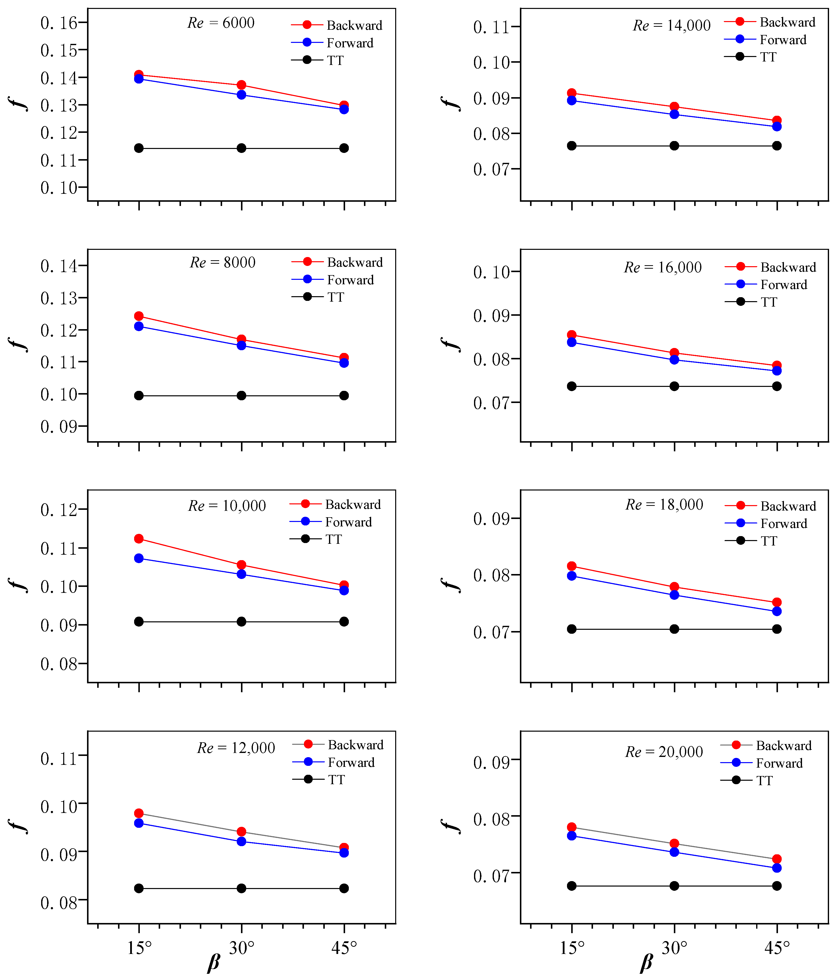
Friction factors (
f) are evaluated from pressure variation in the test section as follows:
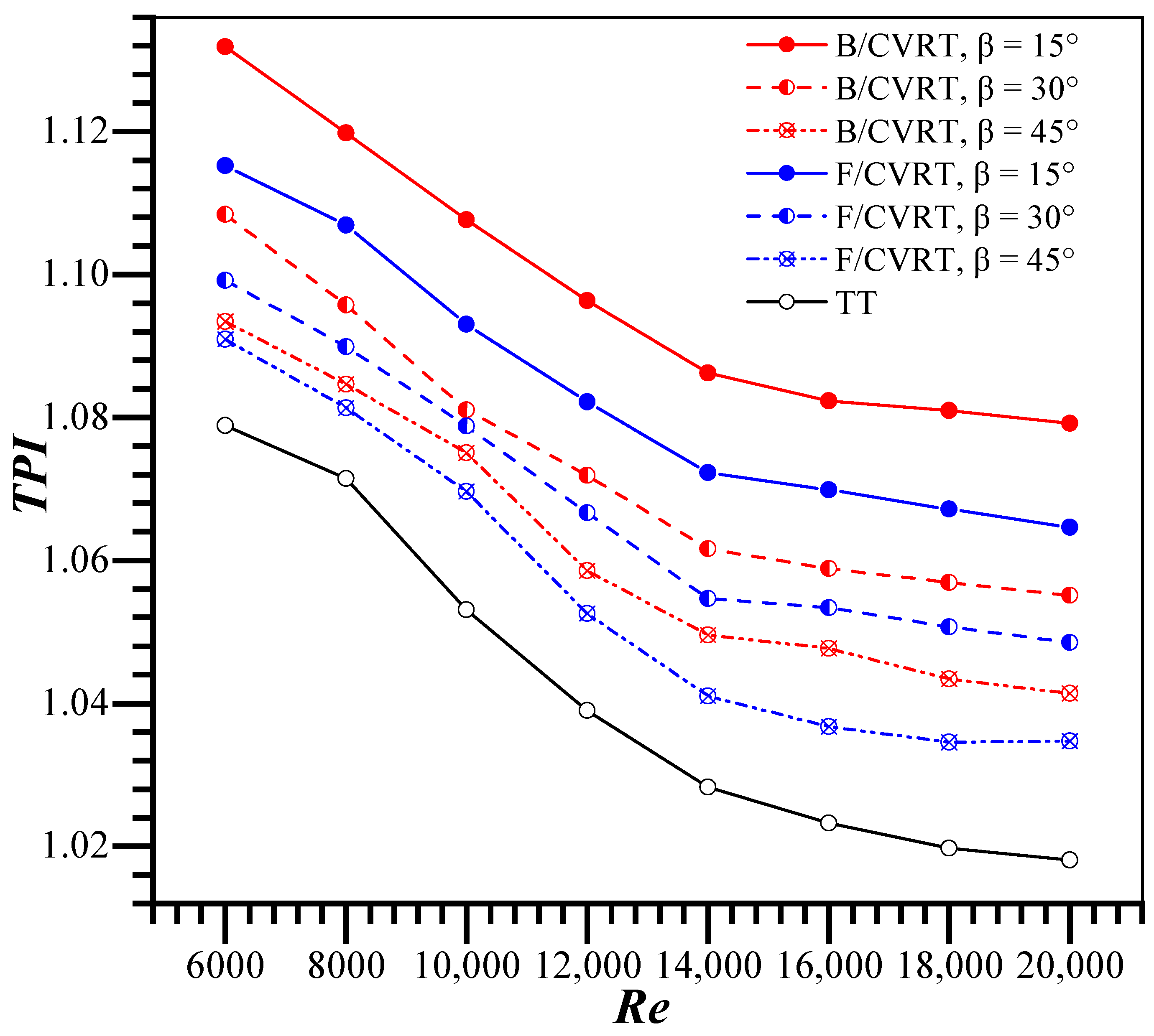
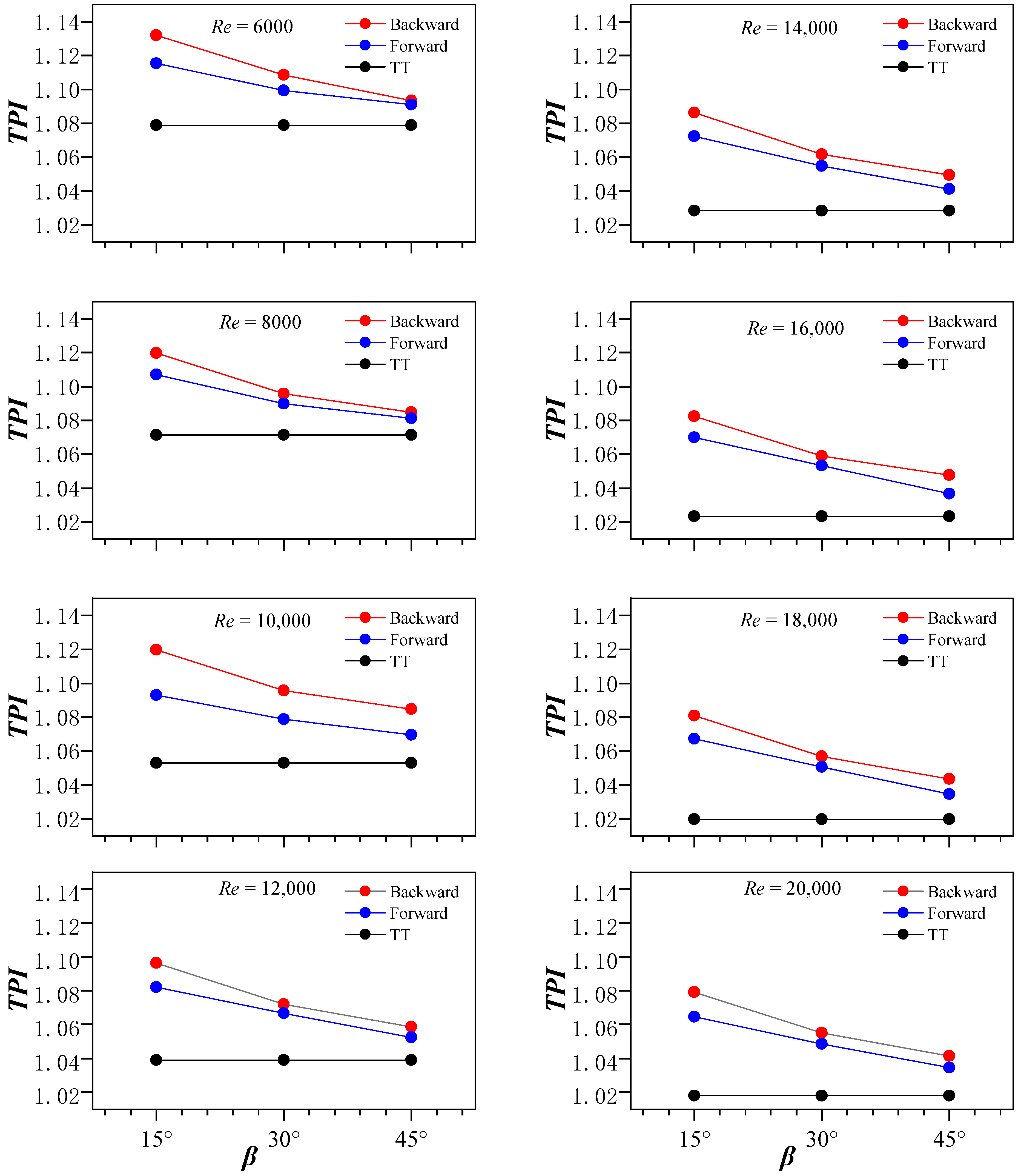
Evaluating the thermal performance based on the Nusselt number is not advisable. Since the pressure loss increases rapidly as the Nusselt number rises, this will lead to higher energy consumption. A comprehensive thermal performance index (
TPI) is adopted based on a balance between augmented friction losses and enhanced thermal exchange [
25,
26]. The thermal performance index (
TPI) is a ratio of the thermal exchange coefficient with an augmentation device compared to that with no augmentation device at an identical pumping power, as follows:
It is essential to conduct an uncertainty analysis to assess the reliability and accuracy of test results, thereby ensuring the validity of the derived conclusions. Previously delineated methodologies were employed to conduct an uncertainty analysis of the current work [
27,
28]. Uncertainty analyses were conducted for important parameters, including
Re,
Nu, and
f, to determine data reliability. It is possible for the Nusselt number and the pressure drop to be uncertain. These uncertainties are set according to previously published guidelines [
27,
28]. Moreover,
Table 3 thoroughly concludes the uncertainties associated with all test parameters used in the present work.
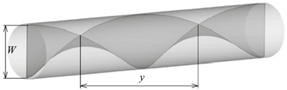
The twist ratio of the continuous V-rib twisted tapes (CVRT) was maintained at 4.0 for all test runs. The twist ratio (TR), also denoted as y/w, is defined as the axial length required for the tape to complete a 180° twist, measured between two corresponding points on co-planar surfaces perpendicular to the tape axis, and normalized by the tape width.
Nusselt Number (
Nu)
where
.
where
.
Friction factor (
f)
where
and
.
The variability for Re, Nu, f, and TPI was ±3.62%, ±4.77%, ±5.73%, and ±4.21%, respectively.
4. Numerical Method
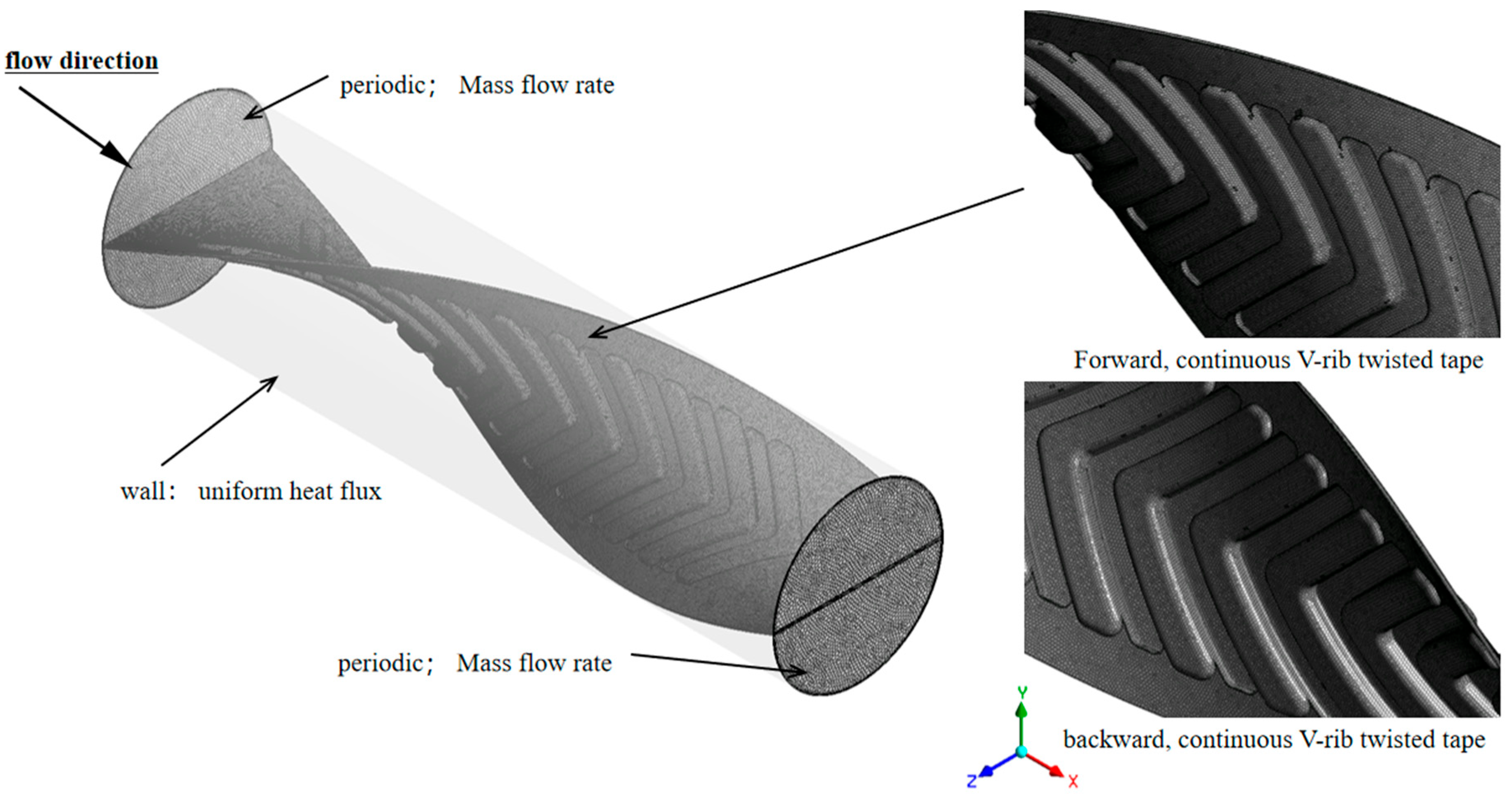
This study utilizes a finite volume method to perform a simulation of periodic turbulent flow in incompressible air, as well as heat transfer for uniform heat flux in round tubes. The study incorporates a variety of swirl generator inserts, such as typical twisted tapes and continuous V-rib twisted tapes, arranged for both forward and backward flows. The current numerical simulation was based on four main assumptions. These are (1) the flow of fluid and heat within a round tube with continuous V-rib twisted-tapes is turbulent, (2) the flow is steady, (3) it does not consider natural convection to the environment, and (4) the fluid’s thermophysical properties do not change with temperature. The governing equations, including the continuity equation, the time-averaged incompressible Navier–Stokes equations, and the energy equation, were applied to describe the conservation of mass, momentum, and thermal energy within the system [
29]. This approach ensures accurate representation of turbulent heat and fluid flow characteristics and their effect on heat transfer processes. Consequently, choosing a proper turbulence model that fits the flow behaviors of each application is crucial. For generating precise aerodynamic predictions for the tube fitted with a continuous V-rib twisted tape, the capability to forecast the renormalized group (RNG)
k-ε turbulence model was studied. The finite-volume method and the SIMPLE algorithm were used to solve the equations that governed the system [
29].
4.1. Procedure for Resolution
In this study, a finite volume technique was used to discretize the steady-state incompressible Navier–Stokes equations, together with a turbulent model, which would achieve stable and reliable solutions. The convective factors were addressed with the QUICK technique to accurately characterize heat and momentum transfer, whilst the diffusive terms were estimated using central differencing to depict viscous and thermal diffusion effects. To enhance numerical stability, the resultant nonlinear equations were solved implicitly. Furthermore, the SIMPLE algorithm was performed to integrate pressure/velocity fields, guaranteeing precise pressure resolution and mass conservation.
The tube surface was reinforced with impermeability and no-slip conditions, while the lower wall of the test area was exposed to an isothermal flux to simulate regulated heating. To restrict heat transfer solely within the test section, both the external tube surface and the transverse twisted-tape surfaces were thermally insulated. Fluid flow periodicity was simulated by applying a periodic boundary condition to emulate cyclical flow characteristics. Under-relaxation coefficients of 0.4 and 0.6 were applied to the pressure and momentum equations, respectively, to maintain a stable iterative solution procedure. Convergence thresholds required the residuals of the mass, momentum, and energy conservation equations to be below 10−6, guaranteeing precise adherence to fundamental physical conservation principles. The numerical simulations were performed at a Reynolds number of 10,000, defined based on the inlet flow conditions. The following assumptions were applied:
- -
A constant mass flow rate was used to maintain periodic flow conditions at each Reynolds number.
- -
The thermophysical properties of air were assumed constant and evaluated at the bulk mean temperature.
- -
A constant wall heat flux of 1000 W/m2 was applied to the tube surface.
- -
The continuous V-rib twisted tapes were assumed to be adiabatic, modeled by imposing a high thermal resistance at their surfaces.
In this study, the Reynolds number is used to characterize the flow regime, which is determined by the mass flow rate at the inlet and outlet of the test section. The average inlet velocity is 0.4748 m/s, corresponding to a Reynolds number (Re) of 10,000, indicating fully developed, single-phase turbulent flow within the tube. In the absence of inserts, the flow inside the tube is purely axial. When a continuous V-rib twisted tape insert is introduced, the flow becomes more complex, transitioning from axial to swirling due to the tape-induced flow modification. For simplicity, the tape thickness is assumed to be negligible. The inlet temperature, working fluid, and thermal boundary conditions are maintained consistently for both with and without the tape insert. A constant wall heat flux of 1000 W/m2 is applied as the boundary condition on the tube surface. The interaction between the fluid (air) and the continuous V-rib twisted tape is modeled using a fluid-structure interaction boundary condition. The presence of the twisted tape significantly alters the velocity and thermal boundary layers, leading to enhanced heat transfer performance. These changes arise from the generation of swirl flow, which results in a distinct velocity profile compared to the plain tube under identical conditions. To evaluate the effects of this modified flow on heat transfer and friction factor, the plain tube (without inserts) is used as a reference case.
In this study, fluid flow behavior is governed by pressure differences, as the flow is pressure-driven. Since the precise pressure values are not critical in this context, the inlet boundary condition is set to zero gauge pressure. The outlet pressure is defined as atmospheric pressure (
P = 1.013 × 10
5 Pa). The pressure drop can be estimated from the difference between the inlet and outlet pressures. The inlet air temperature is maintained at a constant 298 K. A summary of the applied boundary conditions is provided in
Table 4.
4.2. Computational Domain
Figure 3 illustrates the discretization of the computational domain using an unstructured mesh. An enhanced wall treatment model was selected for near-wall modeling, as it relies on a finely resolved near-wall mesh to accurately capture the viscous sublayer. To determine an optimal mesh size for the continuous V-rib twisted tapes (CVRTs), a grid independence study was conducted using Richardson extrapolation on grids with varying cell counts. Polyhedral cells were employed to mesh the surfaces of both the twisted tape and the tube wall, with localized grid refinement applied in the boundary layer regions.
A grid independence study was performed using the periodic module of the typical twisted tape with a twist ratio (y/w) of 4.0 at a Reynolds number of 10,000 by using the RNG k-ε turbulence model. Five different grid densities: 52,055; 192,835; 371,245; 520,002; and 721,271 cells were evaluated. The results indicate that the Nusselt number and friction factor exhibited negligible variation when the grid size increased from 520,002 to 721,271 cells. This suggests that the simulation with a grid number of 520,002 generates data that are sufficiently precise and requires less time to execute than the one with a grid number of 721,271. Nu and f are estimated to have a deviation of approximately ±12.1% and ±14.7%, respectively, in comparison to the current experimental data. For the continuous V-rib twisted tapes (CVRTs) with rib angles (β) of 15°, 30°, and 45°, simulations were carried out using grids of 1,075,742; 1,083,549; and 1,057,525 cells, respectively. The predicted values of Nu and f were found to be sufficiently accurate. The deviations in Nu and f compared to experimental results were ±12.13% and ±14.71% for β = 15°, ±13.39% and ±15.59% for β = 30°, and ±13.17% and ±14.78% for β = 45°, confirming the adequacy of the selected grid resolutions.
The numerical study focused on tapes with specific geometric parameters. These include (1) a rib depth of 1.5 mm, (2) a twist ratio of 4.0, and (3) attack angles of 15°, 30°, and 45°. Tapes arranged in forward and backward configurations were simultaneously considered. These configurations were selected to systematically investigate the continuous V-rib twisted tape effects on flow turbulence, thermal enhancement, and performance of the system.
5. Numerical Findings
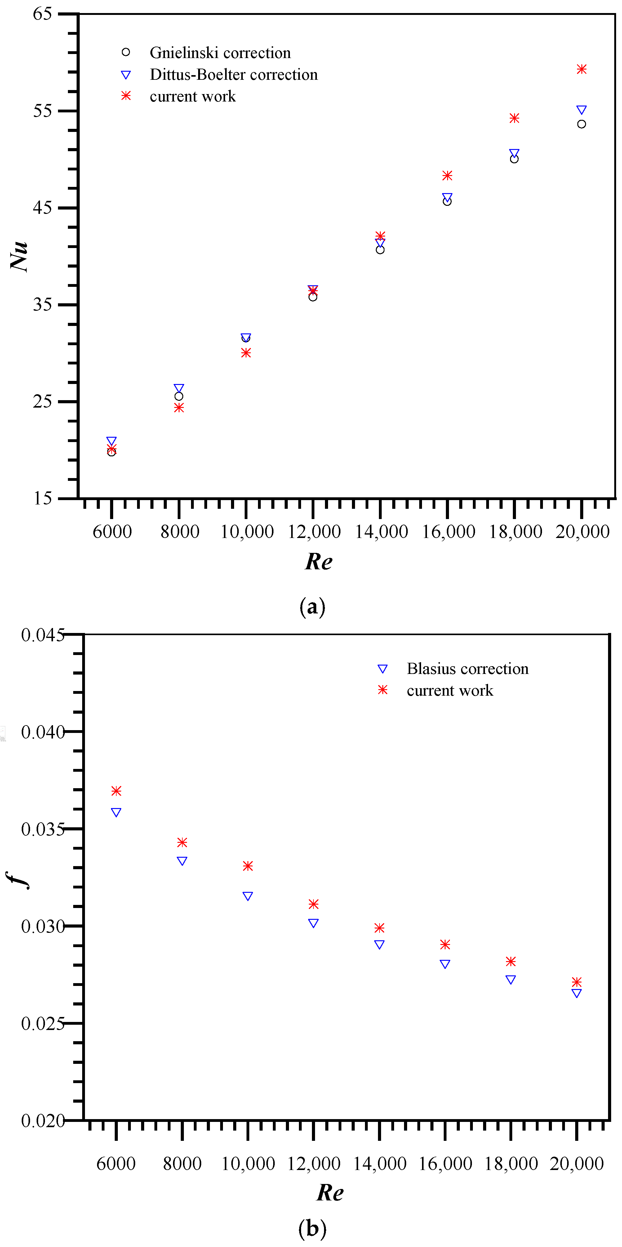
Before the simulation of tubes equipped with continuous V-rib twisted tapes, the numerical results were verified by comparing the current findings (Nusselt number and friction factor) for the plain tube with established correlations found in the literature by Bergman et al. [
30]. The validation was conducted for Reynolds numbers (
Re) of 10,000 in turbulent flow conditions. In the current simulation, the Nusselt numbers diverge from the Dittus–Boelter correlation by ±6.8%, while the numerical friction factor deviates from the Blasius correlation by ±8.9%, respectively. This study also evaluates the reliability of the renormalized group (RNG)
k-ε turbulence model by comparing numerical findings from a tube with a classical twisted tape to previous experimental data [
31]. It can be found that the current numerical Nusselt number and friction factor deviate from previous data by ±12.1% and ±14.7%, respectively.
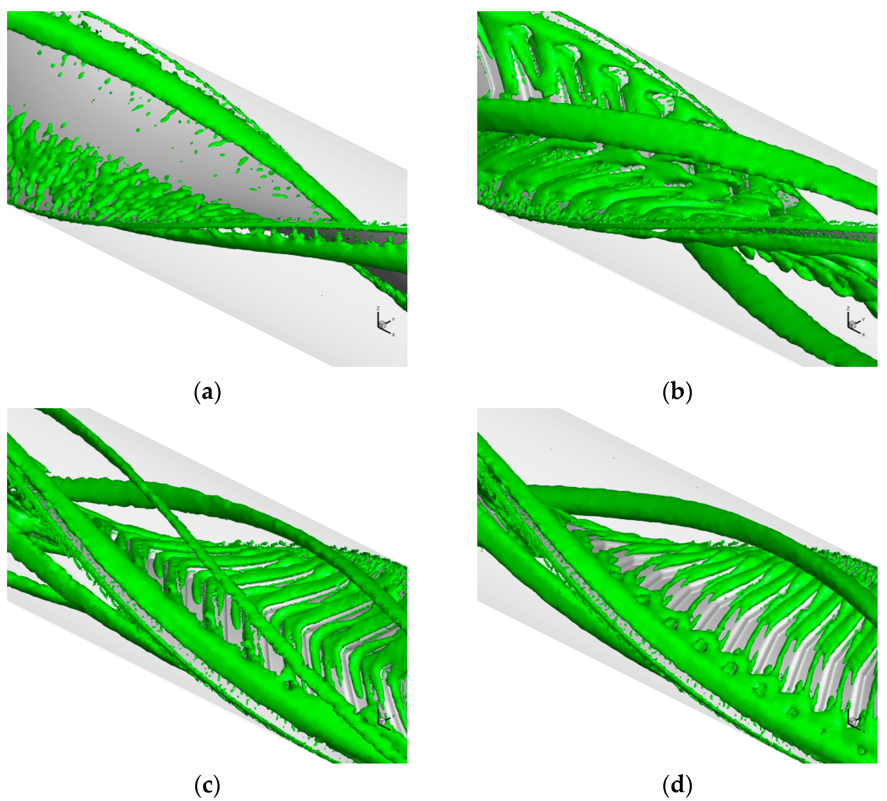
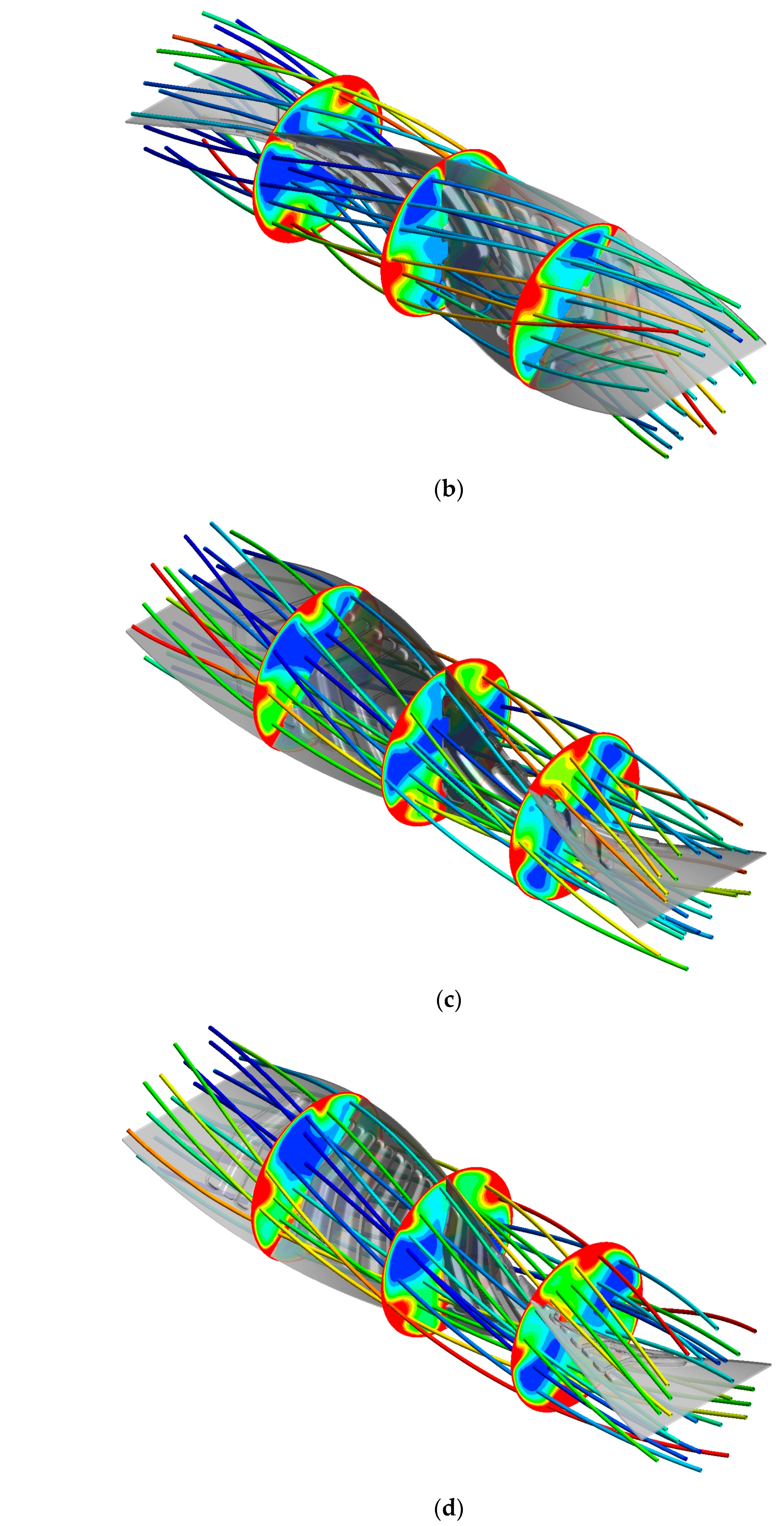
The flow structures within the tubes, including the continuous V-rib twisted tapes, are demonstrated to raise understanding of the heat transfer mechanisms.
Figure 4a–d present the flow structures. All twisted tape inserts, on both the left and right sides of the tape, clearly display axial swirl flows. The boundary layer in the typical twisted tape (TT) configuration is considerably thicker than that in the continuous V-rib twisted tape (CVRT), which contributes to a larger flow separation zone. The continuous V-rib induces longitudinal vortex flows by deflecting the mainstream fluid along its inclined surfaces to both sides, generating a symmetrical secondary flow that enhances fluid mixing and heat transfer. Compared to a conventional twisted tape (TT), the continuous V-rib twisted tape exhibits distinct thermal boundary layer behavior. On the protrusion side of the V-rib, the thermal boundary layer is notably thinner, whereas it becomes thicker on the depression side. These alternating protrusion and depression features enhance flow disturbances, promoting more vigorous fluid motion. The continuous V-ribs generate multiple vortices that form a dense reattachment zone, which significantly enhances fluid mixing and improves near-wall heat transfer performance. Backward V-ribs create a secondary flow along the flow direction and better enhance fluid mixing. Forward V-ribs create a forward vortex flow, which produces a different mixing effect. For a large 45° attack angle, the flow separation is gentle, and the vortex scale is large, but the intensity is weak. As the attack angle decreases, flow separation and reattachment are balanced. The boundary layer becomes increasingly thinner. The vortex structure is denser, the turbulence intensity is significantly enhanced, and the boundary layer is periodically shed, forming a region of high turbulent kinetic energy. The continuous V-rib twisted tapes create both swirling and longitudinal vortex flows, which improve fluid mixing, especially at a smaller attack angle (
β = 15°) arranged backward. This is because they have the largest blockage area, which creates the strongest longitudinal vortex flows.
Figure 5 and
Figure 6 demonstrate the contours of velocity vectors, TKE, and fluid temperature within a round tube containing twisted tape inserts. As displayed in
Figure 5a, a typical twisted tape insert provides relatively low and symmetrical TKE distribution. The flow is smooth, no significant vortex structure can be found, and the boundary layer is thick. The continuous V-rib twisted tape inserts exhibit higher TKE with a distribution mode, which is accompanied by significantly alternating and disordered vector directions. The phenomenon indicates that the V-ribs increase flow complexity.
Figure 5b,c illustrate the differences between the forward and backward arrangement. The backward-arranged tape creates more disturbance.
Figure 5d shows that the tape with a smaller attack angle,
β = 15°, has the most complex distribution and irregular vector distribution. The wall displays streams of swirling flow, while the continuous V-rib twisted tapes, positioned behind the tube core, induce longitudinal vortex flow. The CVRTs induced additional swirling flow near the ribs. Swirling and longitudinal vortex flows promote wall and core flow zone mixing. The vortex structure is dense and evenly distributed, while the boundary layer is periodically broken and reattached. The temperature distribution (
Figure 6) is consistent with the TKE region, which verifies the effect of continuous V-ribs on turbulent disturbance with thermal boundary layer destruction and air mixing.
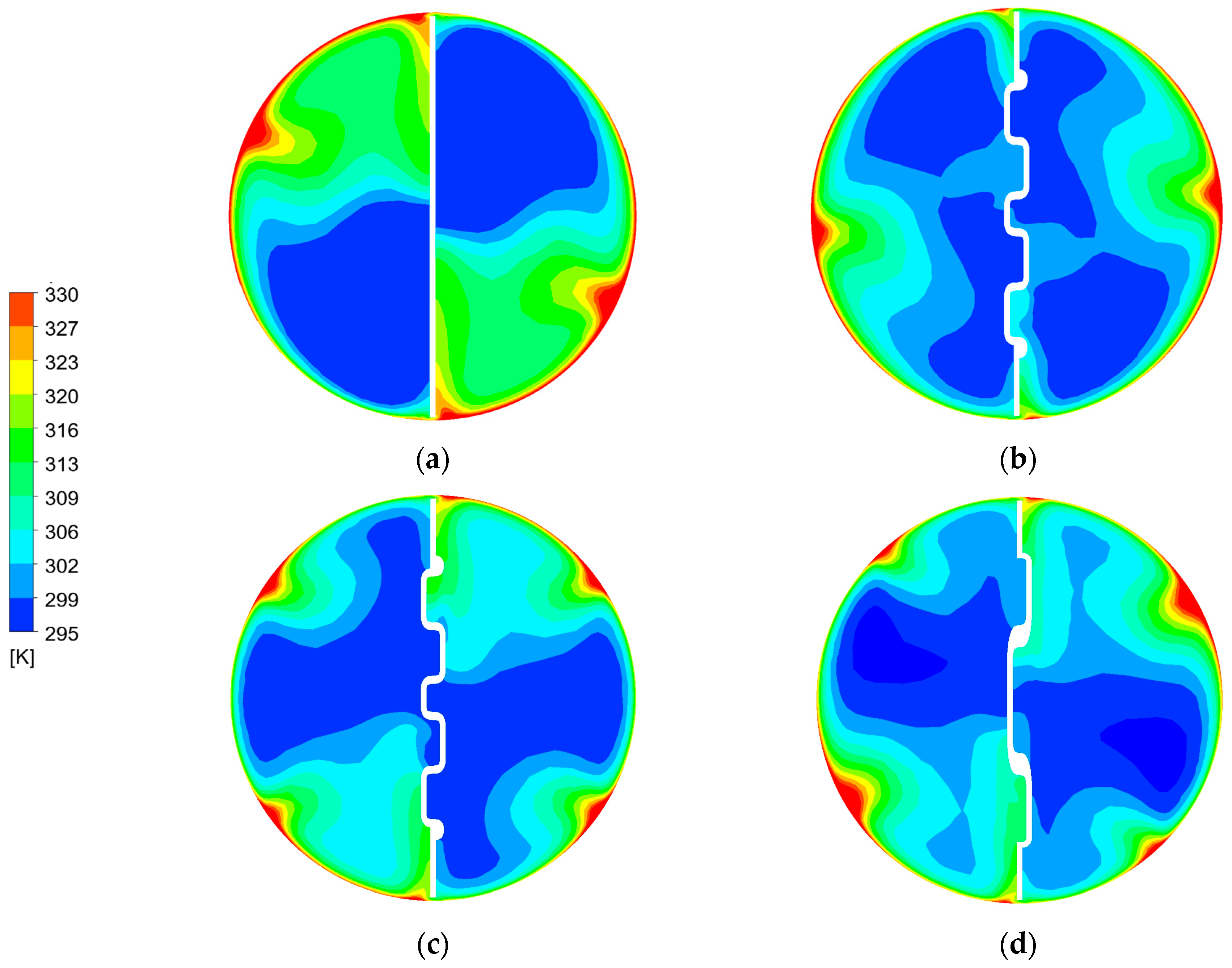
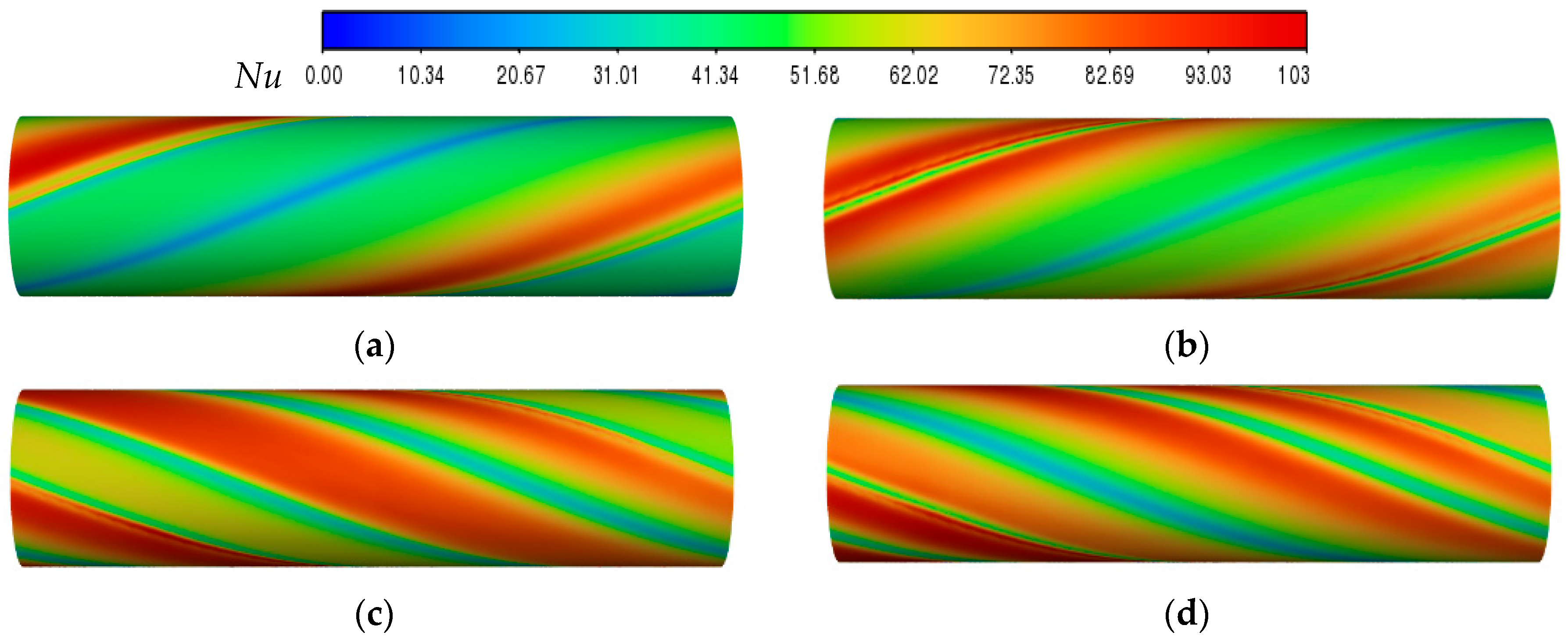
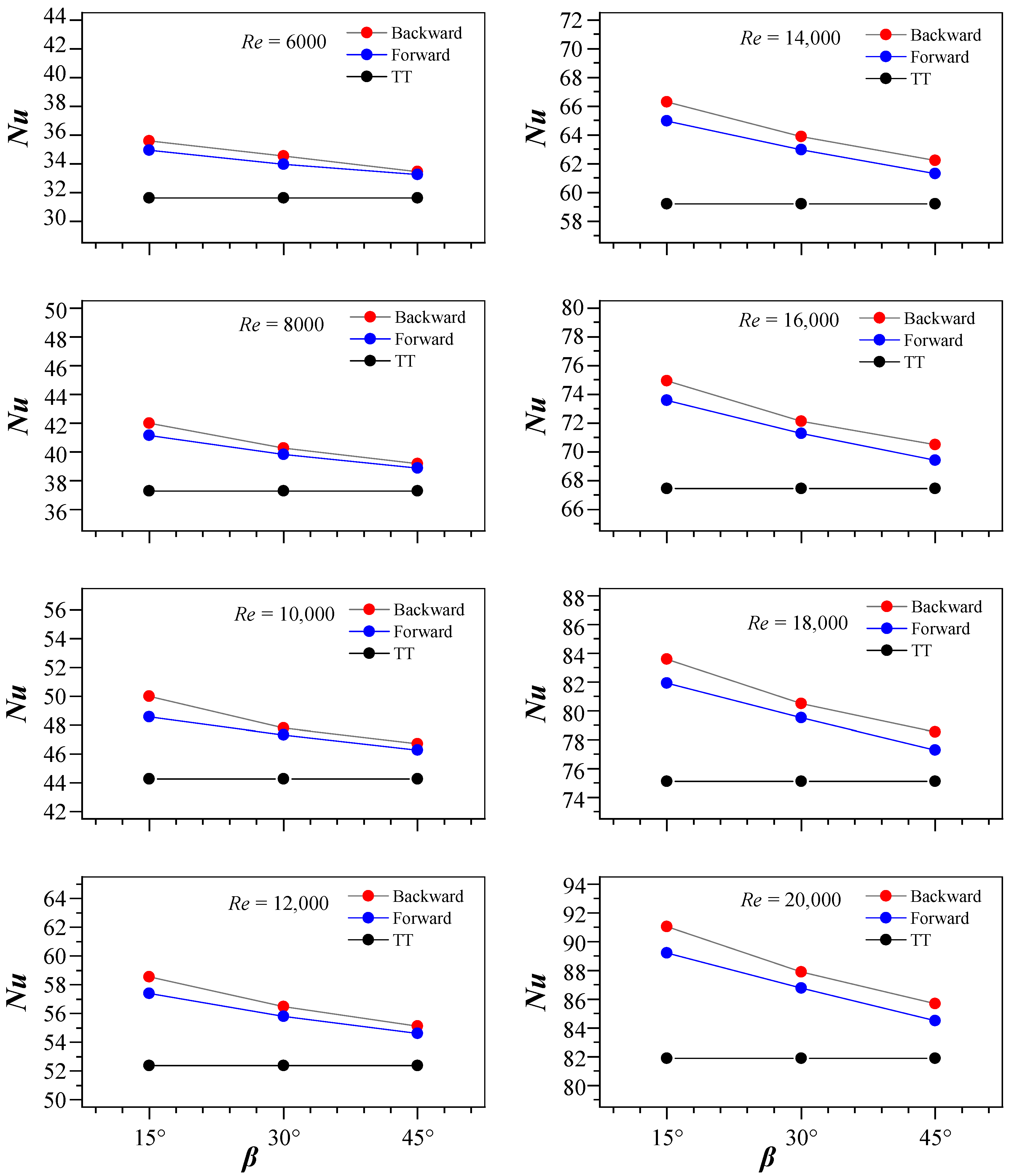
Figure 7a–d present the contour plots of streamlines and temperature fields for tubes fitted with a typical twisted tape (TT) and continuous V-rib twisted tapes (CVRTs) at various attack angles (β), evaluated at a Reynolds number of 10,000. The temperature distribution for the TT case reveals two distinct regions of extremely high and low temperatures, indicating poor thermal mixing and limited disruption of the thermal boundary layer. This non-uniformity suggests that the TT generates relatively weak secondary flow structures, which are insufficient to enhance heat transfer effectively across the tube’s cross-section. In contrast, the CVRT configurations exhibit significantly more uniform temperature fields and thinner thermal boundary layers along the tube wall. The presence of continuous V-shaped ribs promotes stronger secondary flows and more vigorous fluid mixing.
Figure 8a–d illustrate the local Nusselt number along the tube wall with various continuous V-rib twisted tape inserts. Overall, the Nusselt number distributions in tubes with continuous V-rib twisted tapes exhibit more uniformity compared to those with a TT, as seen in
Figure 8a. Swirl and longitudinal flows facilitate enhanced fluid mixing, resulting in more uniform Nusselt number distributions. In
Figure 8a, elevated Nusselt numbers are observed at only one location adjacent to the borders of the TT. Nevertheless, the continuous V-rib twisted tape exhibits two or more locations with high Nusselt numbers, especially for the backward-arranged tape, which had two of these locations at the center of the continuous V-rib, as illustrated in
Figure 8b–d. This is attributed to the greater protrusions of the CVRTs. Continuous V-rib twisted tapes generate enhanced turbulence, resulting in better heat transfer. These twisted tapes at all attack angles (
β = 15°, 30°, and 45°) have superior heat transfer compared to a TT, especially at the lowest attack angle (
β = 15°).

 ,
, 


