
Thinned Eisenstein Fractal Antenna Array Using Multi-Objective Optimization for Wideband Performance

 , , , and
Abstract
1. Introduction
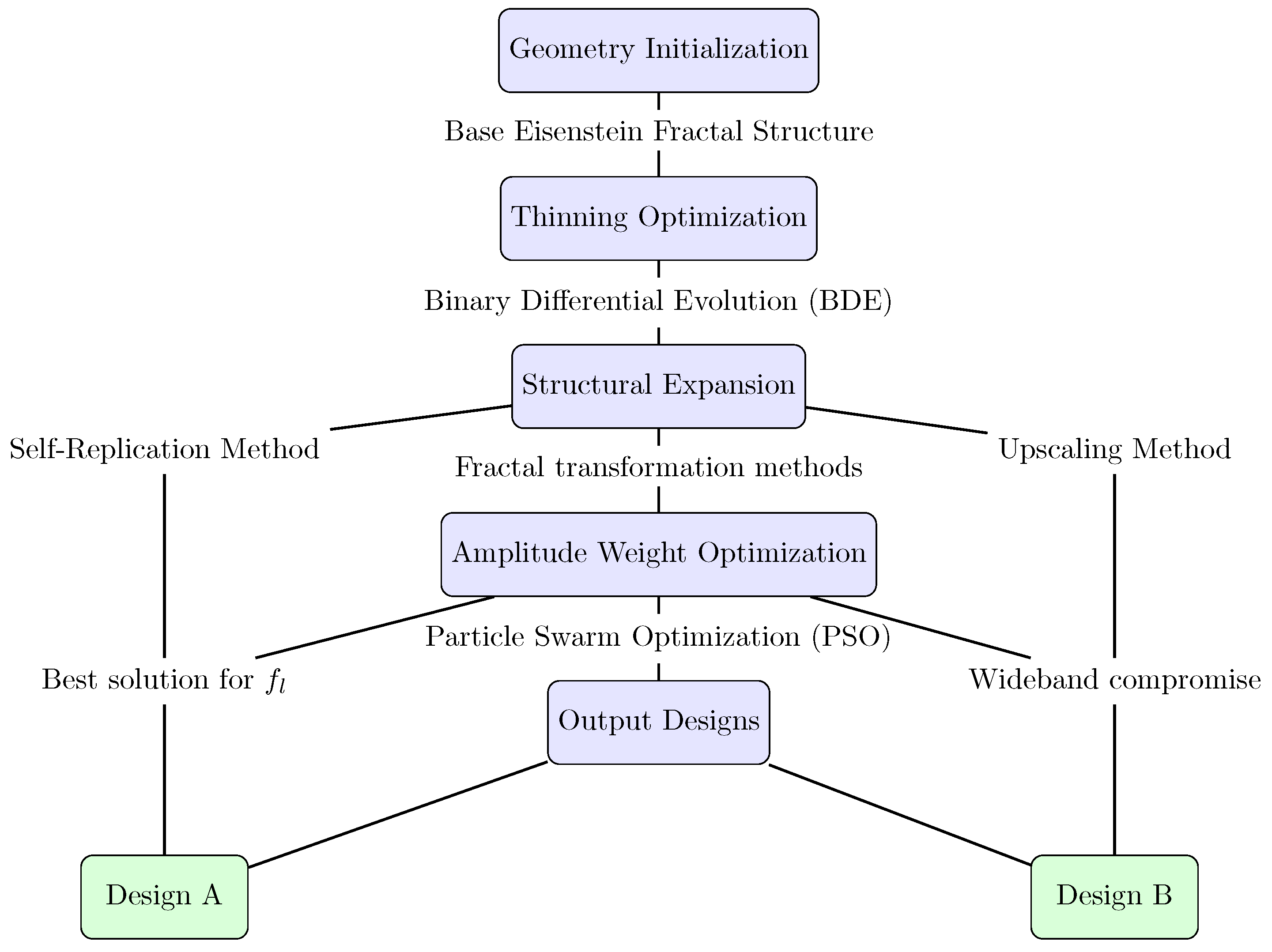
2. Methodology
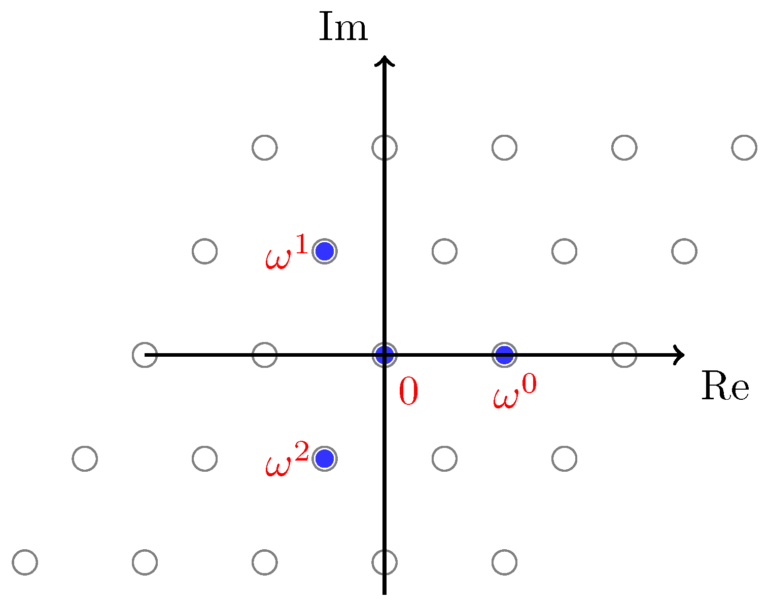
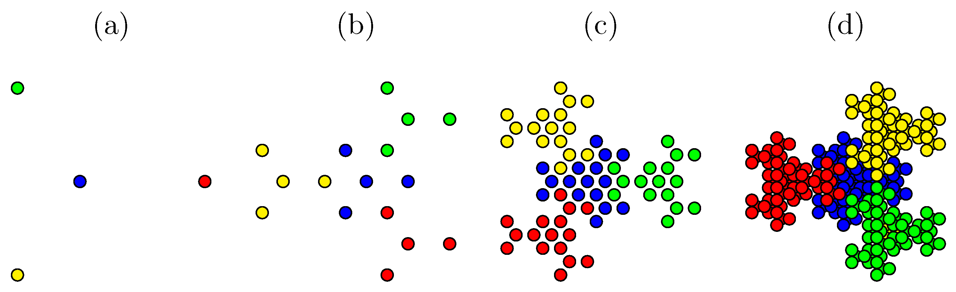
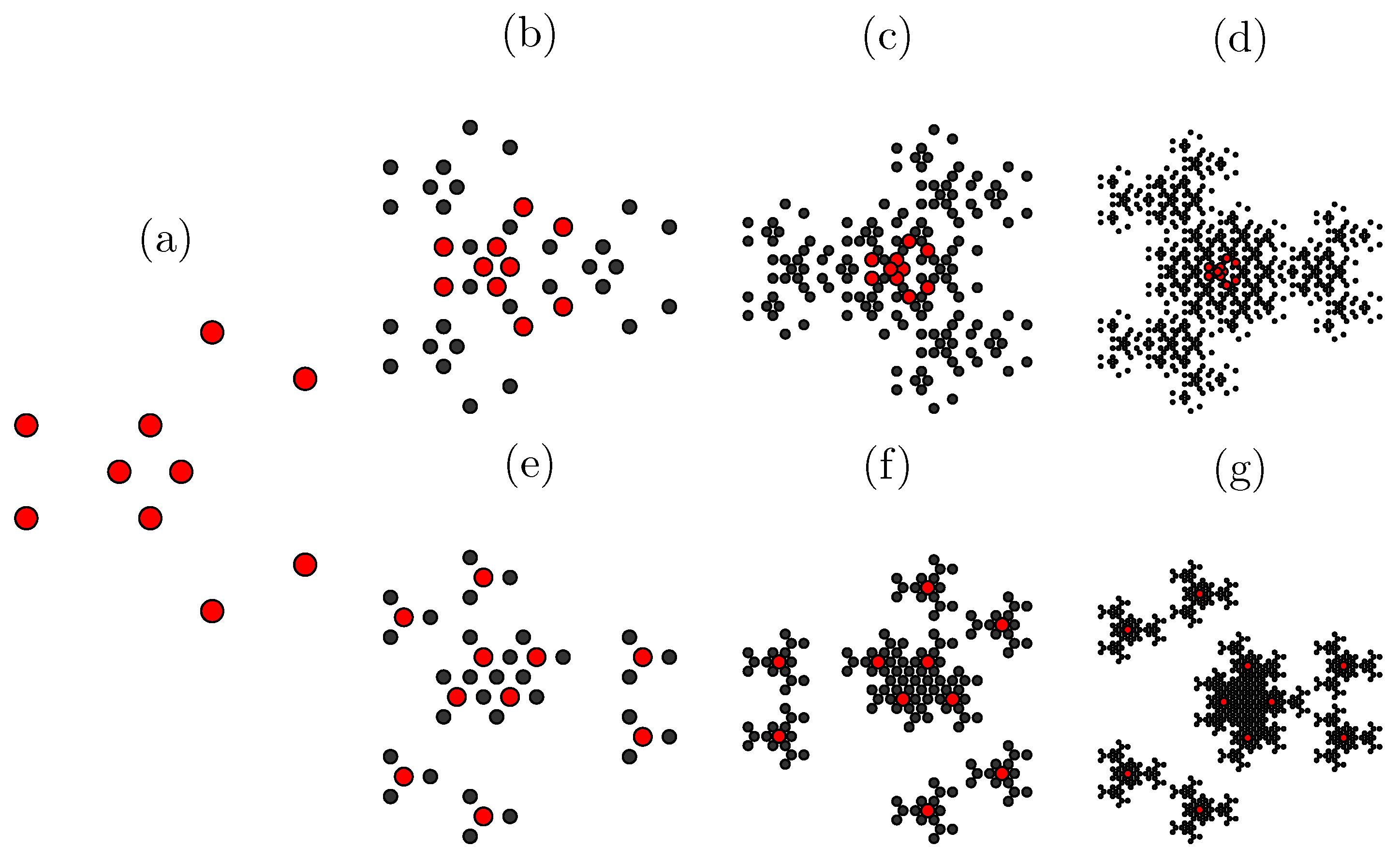
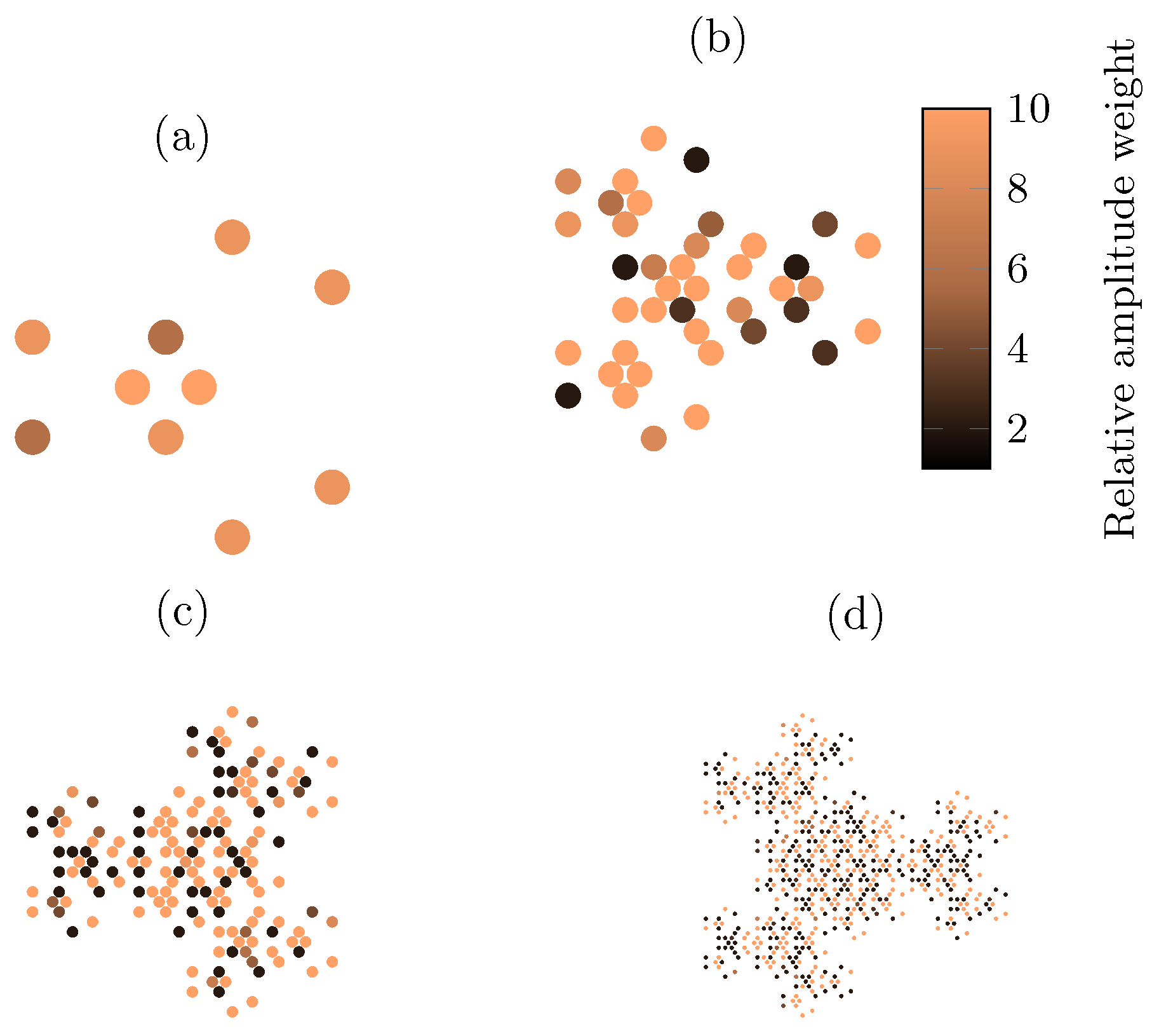
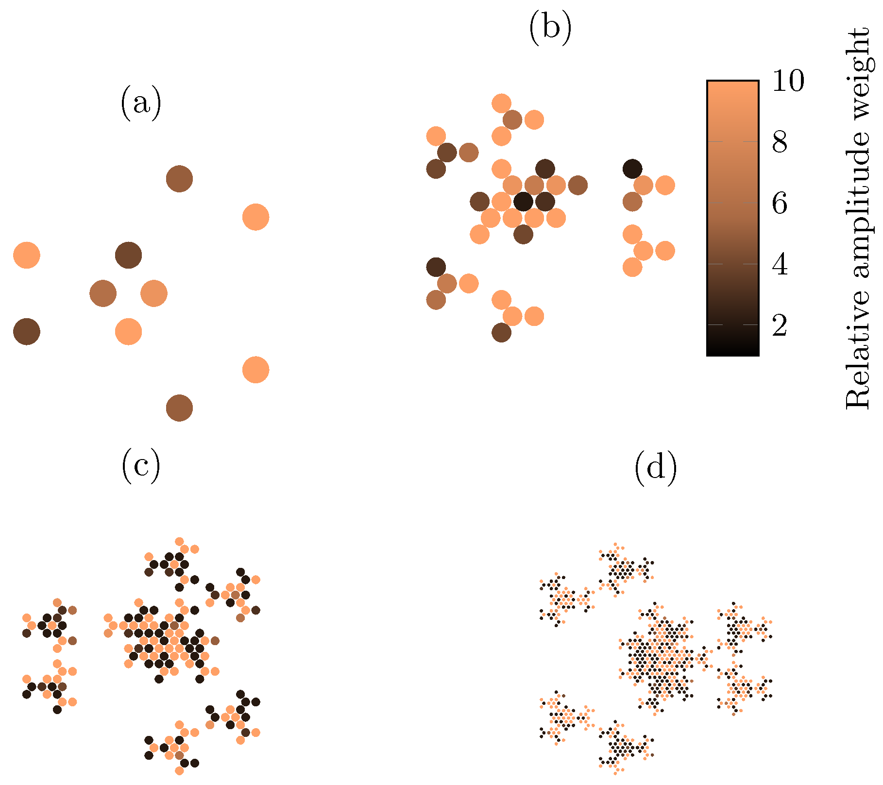
2.1. The Eisenstein Fractal Generator
2.2. Array Factor and Parameter Calculation
2.3. Optimization Process
| Algorithm 1: MO-BDE for Antenna Array Thinning |
|
| Algorithm 2: MO-PSO for Amplitude Excitation Tuning |
|
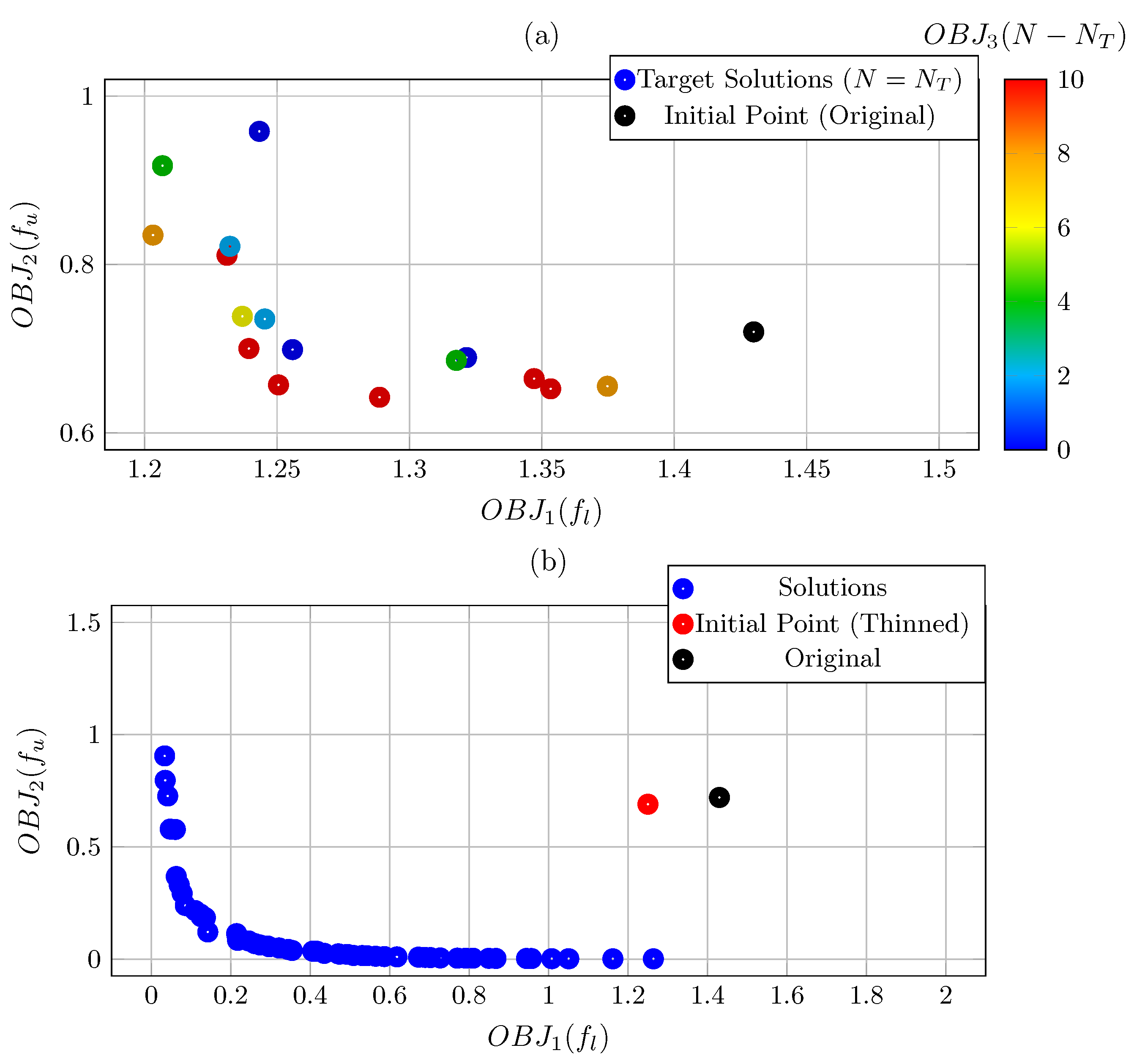
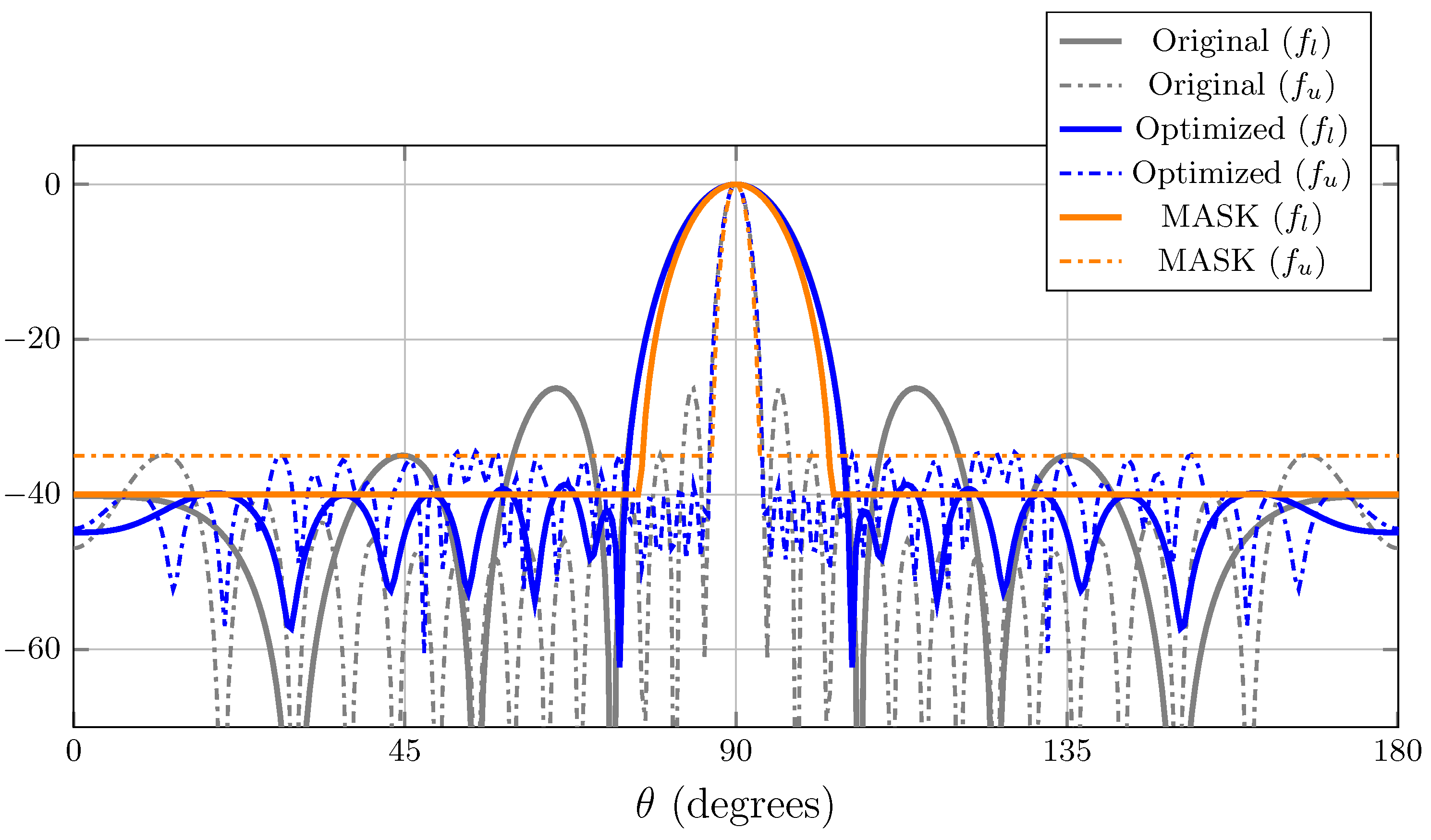
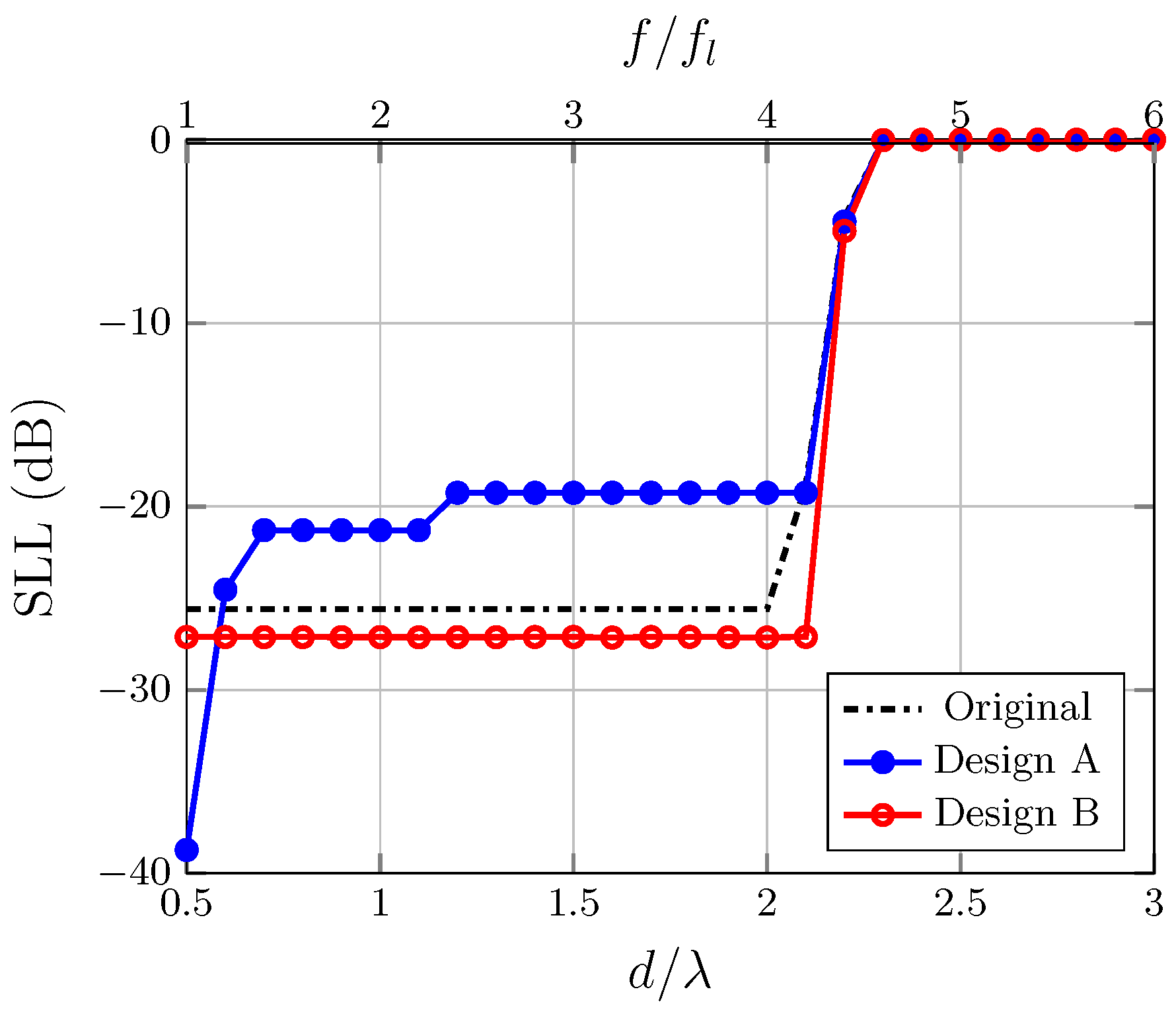
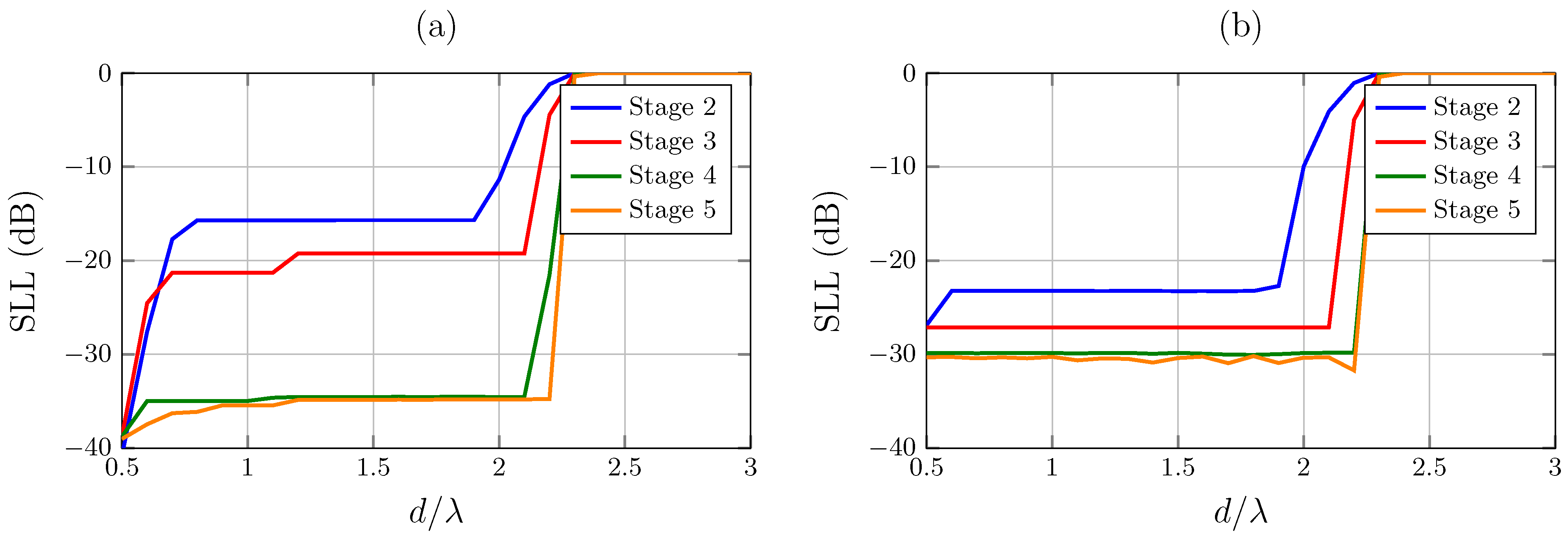
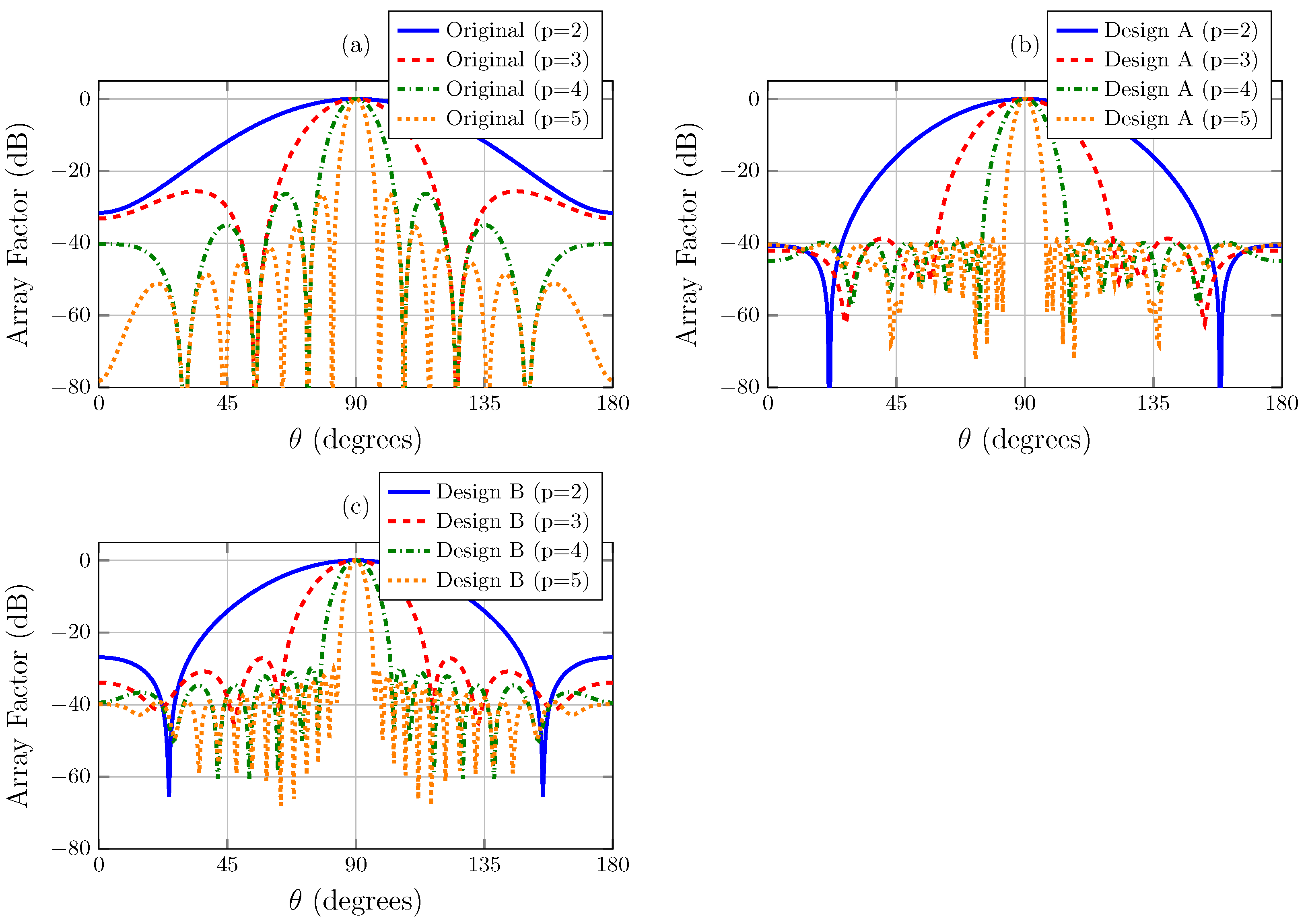
3. Results
- Design A: initial frequency optimization ();
- Design B: wideband compromise optimization ( to ).
4. Discussion
5. Conclusions
Author Contributions
Funding
Institutional Review Board Statement
Informed Consent Statement
Data Availability Statement
Conflicts of Interest
References
- Wang, C.-X.; Feng, R.; Sun, H.; Liu, J.; Xie, Y.; Gao, X.; Liu, L.; Li, Y.; Wang, M.; You, X.; et al. On the Road to 6G: Visions, Requirements, Key Technologies and Testbeds. arXiv 2023, arXiv:2302.14536. [Google Scholar] [CrossRef]
- Figueiredo, F.A.P. An Overview of Massive MIMO for 5G and 6G. IEEE Lat. Am. Trans. 2022, 20, 931–940. [Google Scholar] [CrossRef]
- Reddy, M.H.; Sheela, D. MIMO antenna design and optimization with enhanced bandwidth for wireless applications. J. Telecommun. Inf. Technol. 2020, 4, 22–26. [Google Scholar] [CrossRef]
- Karmakar, A. Fractal antennas and arrays: A review and recent developments. Int. J. Microw. Wirel. Technol. 2021, 13, 173–197. [Google Scholar] [CrossRef]
- Chand Ravi, K.; Kumar, J.; Elwi, T.A.; Mahdi Ali, M. Compact MIMO antenna for 5G Applications. In Proceedings of the 2022 IEEE ANDESCON, Quito, Ecuador, 13–15 October 2022; IEEE: Piscataway, NJ, USA, 2022; pp. 1–4. [Google Scholar] [CrossRef]
- Palanisamy, S.; Thangaraju, B.; Khalaf, O.I.; Alotaibi, Y.; Alghamdi, S.; Alassery, F. A novel approach of design and analysis of a hexagonal fractal antenna array (HFAA) for next-generation wireless communication. Energies 2021, 14, 6204. [Google Scholar] [CrossRef]
- Hohlfeld, R.G.; Cohen, N. Self-similarity and the geometric requirements for frequency independence in antennas. Fractals 1999, 7, 79–84. [Google Scholar] [CrossRef]
- Anguera, J.; Puente, C.; Borja, C.; Soler, J. Fractal antennas: An historical perspective. Fractal Fract. 2020, 4, 3. [Google Scholar] [CrossRef]
- Spence, T.G.; Werner, D.H. Design of broadband planar arrays based on the optimization of aperiodic tilings. IEEE Trans. Antennas Propag. 2008, 56, 76–86. [Google Scholar] [CrossRef]
- Hussein, R.T.; Jibrael, F.J. Comparison of the radiation pattern of fractal and conventional linear array antenna. Prog. Electromagn. Res. Lett. 2008, 4, 183–190. [Google Scholar] [CrossRef]
- Werner, D.H.; Kuhirun, W.; Werner, P.L. A new design methodology for modular broadband arrays based on fractal tilings. In Proceedings of the 2003 IEEE Topical Conference on Wireless Communication Technology, Honolulu, HI, USA, 15 October 2003; pp. 267–268. [Google Scholar] [CrossRef]
- Werner, D.H.; Kuhirun, W.; Werner, P.L. Fractile arrays: A new class of tiled arrays with fractal boundaries. IEEE Trans. Antennas Propag. 2004, 52, 2008–2018. [Google Scholar] [CrossRef]
- Spence, T.G.; Werner, D.H.; Carvajal, J.N. Modular broadband phased-arrays based on a nonuniform distribution of elements along the peano-gosper space-filling curve. IEEE Trans. Antennas Propag. 2010, 58, 600–604. [Google Scholar] [CrossRef]
- Gregory, M.D.; Namin, F.A.; Werner, D.H. Exploiting rotational symmetry for the design of ultra-wideband planar phased array layouts. IEEE Trans. Antennas Propag. 2013, 61, 176–184. [Google Scholar] [CrossRef]
- Ponnapalli, V.A.S.; Jayasree, P.V.Y. Heptagonal fractal antenna array for wireless communications. In Advances in Signal Processing and Communication; Reddy, P.S., Thangavel, M., Prabhakar, S., Eds.; Springer: New Delhi, India, 2016; pp. 387–394. [Google Scholar] [CrossRef]
- El-Khamy, S.E.; Eltrass, A.S.; El-Sayed, H.F. Generator optimization for thinned fractal hexagonal and pentagonal antenna arrays using Ant Colony algorithm. In Proceedings of the 2017 34th National Radio Science Conference (NRSC), Alexandria, Egypt, 13–16 March 2017; pp. 71–78. [Google Scholar] [CrossRef]
- Panduro, M.A.; Reyna, A.; Covarrubias, D.H. Non-Uniform Concentric Rings Design for Ultra-Wideband Arrays. Sensors 2019, 19, 2262. [Google Scholar] [CrossRef] [PubMed]
- Liu, S.; Chen, L.; Liu, Y. Design of Parameter-Optimized Spiral Arrays with Ultra-Wideband Grating Lobe Suppression. Electronics 2023, 12, 1664. [Google Scholar] [CrossRef]
- Dahl, C.; Vogt, M.; Rolfes, I. A MIMO Radar System based on Fractal Antenna Arrays for Level Measurement Applications. Adv. Radio Sci. 2021, 19, 23–29. [Google Scholar] [CrossRef]
- Dong, Y.; Cai, X.; Geyi, W. A Weighted Method for Multi-Beam Synthesis with Controllable Gain and Sidelobe Suppression. IEEE Trans. Antennas Propag. 2025. [Google Scholar] [CrossRef]
- Beccaria, M.; Massaccesi, A.; Pirinoli, P.; Manh, L.H. Multibeam Transmitarrays for 5G Antenna Systems. In Proceedings of the 2018 IEEE International Conference on Communications and Electronics (ICCE), Hue, Vietnam, 18–20 July 2018; pp. 217–221. [Google Scholar]
- El-Khamy, S.E.; El-Sayed, H.F.; Eltrass, A.S. Synthesis of Wideband Thinned Eisenstein Fractile Antenna Arrays with Adaptive Beamforming Capability and Reduced Side-Lobes. IEEE Access 2022, 10, 122486–122500. [Google Scholar] [CrossRef]
- Helmberg, G. On the Eisenstein Packing of the Complex Plane. Math. Intell. 2015, 37, 27–33. [Google Scholar] [CrossRef]
- Balanis, C.A. Antenna Theory: Analysis and Design, 4th ed.; Wiley: Hoboken, NJ, USA, 2016. [Google Scholar]
- Stutzman, W.L.; Thiele, G.A. Antenna Theory and Design, 3rd ed.; Wiley: Hoboken, NJ, USA, 2013. [Google Scholar]
- Eberhart, R.C.; Shi, Y. Particle Swarm Optimization: Developments, Applications and Resources. In Proceedings of the 2001 Congress on Evolutionary Computation (CEC2001), Seoul, Republic of Korea, 27–30 May 2001; pp. 81–86. [Google Scholar] [CrossRef]
- Pampará, G.; Engelbrecht, A.P.; Franken, N. Binary Differential Evolution. In Proceedings of the 2006 IEEE Congress on Evolutionary Computation, Vancouver, BC, Canada, 16–21 July 2006; pp. 1873–1879. [Google Scholar] [CrossRef]
- Schlosser, E.R.; Tolfo, S.M.; Heckler, M.V.T. Particle Swarm Optimization for antenna arrays synthesis. In Proceedings of the 2015 SBMO/IEEE MTT-S International Microwave and Optoelectronics Conference (IMOC), Porto de Galinhas, Brazil, 3–6 November 2015; pp. 1–6. [Google Scholar] [CrossRef]
- Alnahwi, F.M.; Al-Yasir, Y.I.A.; Sattar, D.; Ali, R.S.; See, C.H.; Abd-Alhameed, R.A. A New Optimization Algorithm Based on the Fungi Kingdom Expansion Behavior for Antenna Applications. Electronics 2021, 10, 2057. [Google Scholar] [CrossRef]
- Petko, J.S.; Werner, D.H. The Pareto optimization of ultrawideband polyfractal arrays. IEEE Trans. Antennas Propag. 2008, 56, 97–107. [Google Scholar] [CrossRef]
- Deligkaris, K.V.; Zaharis, Z.D.; Kampitaki, D.G.; Goudos, S.K.; Rekanos, I.T.; Spasos, M.N. Thinned Planar Array Design Using Boolean PSO with Velocity Mutation. IEEE Trans. Magn. 2009, 45, 1490–1493. [Google Scholar] [CrossRef]
- Mondal, A.K.; Saxena, P. Thinning of Concentric Circular Antenna Array Using Binary Salp Swarm Algorithm. In Proceedings of the 2019 IEEE Conference on Information and Communication Technology (CICT), Allahabad, India, 6–8 December 2019; pp. 1–4. [Google Scholar] [CrossRef]
- Wang, R.Q.; Jiao, Y.C. Synthesis of Wideband Rotationally Symmetric Sparse Circular Arrays with Multiple Constraints. IEEE Antennas Wirel. Propag. Lett. 2019, 18, 821–825. [Google Scholar] [CrossRef]
- El-Khamy, S.E.; Eltrass, A.S.; El-Sayed, H.F. Design of thinned fractal antenna arrays for adaptive beam forming and sidelobe reduction. IET Microwaves Antennas Propag. 2018, 12, 435–441. [Google Scholar] [CrossRef]
- Kundu, K.; Rai, A.; Singh, R.P. Role of IoT and Antenna Array in Smart Communication and 5G. In Paradigms of Smart and Intelligent Communication, 5G and Beyond; Rai, A., Kumar Singh, D., Sehgal, A., Cengiz, K., Eds.; Transactions on Computer Systems and Networks; Springer: Singapore, 2023; pp. 41–58. [Google Scholar] [CrossRef]
- Kedar, A. Phased Array Antenna for Radar Application. In Handbook of Metrology and Applications; Aswal, D.K., Yadav, S., Takatsuji, T., Rachakonda, P., Kumar, H., Eds.; Springer: Singapore, 2023; pp. 811–828. [Google Scholar] [CrossRef]


| Index | ||
|---|---|---|
| 1 | 0 | |
| 2 | 1 | |
| 3 | ||
| 4 | ||
| 5 | ||
| 6 | ||
| 7 | ||
| 8 | ||
| 9 | ||
| 10 | ||
| 11 | ||
| 12 | ||
| 13 | ||
| 14 | ||
| 15 | ||
| 16 |
| SIMULATION PARAMETERS | |
|---|---|
| Population size | 2000 |
| Number of generations | 2000 |
| Evaluation angle samples () | 1440 |
| Fractal structure stages | |
| Individual gene size | |
| MO-BDE | |
| Thinning factor | 0.625 |
| Differential weight parameter (F) | 2 |
| Crossover probability () | 0.75 |
| Mutation probability () | |
| Average duration at stages | 30 m 85 m 160 m 760 m |
| MO-PSO | |
| Amplitude weight values | |
| Initial inertia weight | = 2 |
| Initial acceleration coefficient | |
| Average duration at stages | 6 m 35 m 82 m 260 m |
| Array Structure | Elements | Bandwidth | SLL at (dB) | SLL over Bandwidth (dB) |
|---|---|---|---|---|
| Planar | 64 | 1:1 | −12.76 | – |
| 256 | 1:1 | −13.14 | – | |
| Original Eisenstein | 64 | 4:1 | −25.59 | −25.59 |
| 256 | 4.2:1 | −26.29 | −26.28 | |
| Design A | 40 | 4:1 | −38.72 | −19.25 |
| 160 | 4.2:1 | −38.74 | −34.55 | |
| Design B | 40 | 4:1 | −27.17 | −27.17 |
| 160 | 4.2:1 | −29.86 | −29.83 |
| Stage | Design A | Design B |
|---|---|---|
| 2 | [10,0,9,6,0,9,9,0,0,10,6,9,0,9,0,9] | [9,0,10,4,0,10,5,0,0,6,4,10,0,10,0,5] |
| 3 | [10,0,3,10,0,4,10,0,0,10,10,2,0,10,0,5, 10,0,10,10,0,10,8,0,0,10,2,10,0,10,0,10, 10,0,9,10,0,8,7,0,0,6,9,8,0,2,0,10, 9,0,3,2,0,10,3,0,0,10,8,10,0,10,0,4] | [10,10,4,2,0,0,0,0,10,10,10,4,9,5,3,3, 0,0,0,0,10,10,4,10,7,10,6,3,0,0,0,0, 0,0,0,0,9,7,10,10,4,6,4,10,6,10,10,10, 0,0,0,0,10,10,10,10,0,0,0,0,9,10,6,2] |
| 4 | [10,0,10,2,0,2,2,0,0,9,10,10,0,10,0,2, 10,0,10,10,0,10,2,0,0,10,10,2,0,10,0,2, 10,0,10,10,0,10,10,0,0,10,2,2,0,10,0,10, 10,0,2,10,0,10,10,0,0,2,10,10,0,2,0,10, 2,0,2,2,0,10,2,0,0,10,2,2,0,10,0,5, 10,0,4,2,0,10,2,0,0,5,10,10,0,10,0,10, 10,0,10,5,0,10,2,0,0,2,2,2,0,4,0,9, 10,0,2,2,0,10,10,0,0,10,2,10,0,10,0,10, 10,0,10,10,0,9,2,0,0,10,2,2,0,10,0,10, 10,0,2,10,0,9,2,0,0,10,4,10,0,10,0,3, 10,0,2,10,0,4,2,0,0,2,6,2,0,6,0,10, 2,0,4,10,0,10,10,0,0,10,2,4,0,10,0,2, 10,0,6,5,0,10,2,0,0,10,10,10,0,10,0,10, 10,0,2,2,0,10,10,0,0,7,10,10,0,5,0,2, 10,0,2,10,0,10,10,0,0,10,2,2,0,10,0,10, 10,0,2,10,0,10,10,0,0,10,10,2,0,8,0,4] | [10,2,2,2,10,10,2,2,2,10,10,10,2,10,10,2, 0,0,0,0,0,0,0,0,0,0,0,0,0,0,0,0, 10,10,3,2,10,10,3,2,10,10,9,10,2,2,2,10, 2,10,10,2,10,10,2,2,10,10,2,10,10,5,2,2, 0,0,0,0,0,0,0,0,0,0,0,0,2,4,10,10, 10,10,2,2,2,3,2,10,10,10,10,10,10,2,2,2, 10,5,10,2,10,2,3,10,3,6,3,9,0,0,0,0, 0,0,0,0,0,0,0,0,0,0,0,0,0,0,0,0, 0,0,0,0,0,0,0,0,5,10,10,10,2,2,10,10, 10,2,2,10,10,2,2,10,10,2,3,2,10,2,2,2, 2,2,3,10,10,10,2,10,6,2,2,10,10,3,6,10, 3,10,10,2,2,10,10,2,0,0,0,0,0,0,0,0, 0,0,0,0,0,0,0,0,0,0,10,10,10,10,2,2, 10,6,10,2,2,2,10,10,2,10,0,0,0,0,0,0, 0,0,0,0,0,0,0,0,0,10,2,2,10,3,10,10, 10,2,10,9,2,2,2,2,2] |
| Stage | Elements | Original | Elements | Design A | Design B | ||||
|---|---|---|---|---|---|---|---|---|---|
| SLL (dB) | HPBW (°) | SLL (dB) | HPBW (°) | SLL (dB) | HPBW (°) | ||||
| 2 | 0.5 | ON | 63.33 | ON | −40.77 | 55.82 | −26.87 | 59.83 | |
| 1 | 16 | −22.60 | 30.29 | 10 | −15.69 | 26.78 | −23.24 | 28.79 | |
| 1.5 | OFF | −22.60 | 19.77 | OFF | −15.69 | 17.27 | −23.24 | 18.77 | |
| 2 | 0 | −8.64 | 14.77 | 6 | −13.35 | 13.26 | −9.94 | 14.26 | |
| 3 | 0.5 | ON | −25.59 | 29.79 | ON | −38.72 | 28.79 | −27.11 | 27.28 |
| 1 | 64 | −25.59 | 14.77 | 40 | −21.29 | 14.26 | −27.12 | 13.26 | |
| 1.5 | OFF | −25.59 | 9.76 | OFF | −19.25 | 9.26 | −27.11 | 8.76 | |
| 2 | 0 | −25.58 | 7.26 | 24 | −19.25 | 6.75 | −27.14 | 6.75 | |
| 4 | 0.5 | ON | −26.29 | 14.26 | ON | −38.74 | 14.26 | −29.86 | 13.26 |
| 1 | 256 | −26.28 | 7.26 | 160 | −34.96 | 7.26 | −29.85 | 6.25 | |
| 1.5 | OFF | −26.28 | 4.75 | OFF | −34.54 | 4.75 | −29.83 | 4.25 | |
| 2 | 0 | −26.27 | 3.25 | 96 | −34.55 | 3.25 | −29.85 | 3.25 | |
| 5 | 0.5 | ON | −26.46 | 7.26 | ON | −39.01 | 7.26 | −30.30 | 6.25 |
| 1 | 1024 | −26.44 | 3.25 | 640 | −35.42 | 3.25 | −30.26 | 3.25 | |
| 1.5 | OFF | −26.45 | 2.25 | OFF | −34.85 | 2.25 | −30.39 | 2.25 | |
| 2 | 0 | −26.49 | 1.75 | 384 | −34.82 | 1.75 | −30.34 | 1.25 | |
| Ref. | Array Geometry | Elements | SLL (dB) | ||
|---|---|---|---|---|---|
| [13] | Perturbed Peano–Gosper curve | 50 | −8.11 | −7.71 | −7.71 |
| 344 | −10.12 | −9.71 | −9.71 | ||
| [33] | Symmetric sparse circular arrays | 600 | −20.22 | −18.99 | −18.99 |
| [34] | Fractal pentagonal | 13 | −17.64 | −17.64 | −17.64 |
| 49 | −23.12 | −23.12 | −23.12 | ||
| 162 | −28.43 | −28.43 | −28.43 | ||
| [17] | Non-uniform concentric rings | 90 | −24.95 | −10.21 | −10.21 |
| 168 | −26.59 | −12.24 | −12.24 | ||
| [18] | Fermat spiral | 64 | −8.48 | −8.26 | −8.26 |
| 256 | −14.01 | −13.26 | −13.26 | ||
| [22] | Eisenstein fractile | 16 | −22.61 | −22.61 | −22.61 |
| 64 | −25.59 | −25.60 | −25.59 | ||
| [22] | Thinned Eisenstein Fractile | 10 | −34.65 | −13.98 | −13.98 |
| 40 | −32.04 | −13.98 | −13.98 | ||
| This work | Improved thinned Eisenstein fractile | 10 | |||
| 40 | |||||
| 160 | |||||
Disclaimer/Publisher’s Note: The statements, opinions and data contained in all publications are solely those of the individual author(s) and contributor(s) and not of MDPI and/or the editor(s). MDPI and/or the editor(s) disclaim responsibility for any injury to people or property resulting from any ideas, methods, instructions or products referred to in the content. |
© 2025 by the authors. Licensee MDPI, Basel, Switzerland. This article is an open access article distributed under the terms and conditions of the Creative Commons Attribution (CC BY) license (https://creativecommons.org/licenses/by/4.0/).
Share and Cite
Cepeda , L.E.; Garza , L.A.; Panduro , M.A.; Reyna , A.; Zuñiga , M.A. Thinned Eisenstein Fractal Antenna Array Using Multi-Objective Optimization for Wideband Performance. Appl. Sci. 2025, 15, 5584. https://doi.org/10.3390/app15105584
Cepeda LE, Garza LA, Panduro MA, Reyna A, Zuñiga MA. Thinned Eisenstein Fractal Antenna Array Using Multi-Objective Optimization for Wideband Performance. Applied Sciences. 2025; 15(10):5584. https://doi.org/10.3390/app15105584
Chicago/Turabian StyleCepeda , Luis E., Leopoldo A. Garza , Marco A. Panduro , Alberto Reyna , and Manuel A. Zuñiga . 2025. "Thinned Eisenstein Fractal Antenna Array Using Multi-Objective Optimization for Wideband Performance" Applied Sciences 15, no. 10: 5584. https://doi.org/10.3390/app15105584
APA StyleCepeda , L. E., Garza , L. A., Panduro , M. A., Reyna , A., & Zuñiga , M. A. (2025). Thinned Eisenstein Fractal Antenna Array Using Multi-Objective Optimization for Wideband Performance. Applied Sciences, 15(10), 5584. https://doi.org/10.3390/app15105584