4.1. Justification of the Design and Technological Scheme of a Harvester Equipped with Two Mowing Rotors to Ensure Two-Level Mowing of Tall Stalk Forage, and Determination of the Technological Distance Between the Vertical Axes of Mowing Rotors
In countries located in northern parts of Europe and Asia, during silage harvesting, corn is typically not more than 1.5 m, so most forage harvesters are not designed to harvest tall corn stalks.
In countries with warmer climatic conditions, the height of corn stalks reaches 2.5 m.
For instance, in the Southern region of the Republic of Kazakhstan during corn silage harvesting, the average height of corn reaches 2.43 m [
22].
Currently, forage harvesters are equipped with rotary headers for harvesting tall stalks. The use of such headers in the design of trailed harvesters, therefore, complicates the design and increases the cost of the machines.
In recent years, trailed harvesters have been equipped with mowing rotors with L-shaped knives and a radial-blade shredding unit. The main advantage of these machines is that the mowing rotor ensures both grass mowing and windrow pickup. Nevertheless, they are unable to facilitate mowing of corn stalks with a height of more than 2.0 m, leading to significant losses. Therefore, such machines are not recommended for harvesting tall stalks.
For example, the technical specifications of the KSD-2 forage harvester indicate that its use is not recommended for mowing tall-stemmed plants exceeding 1.5 m in height [
15].
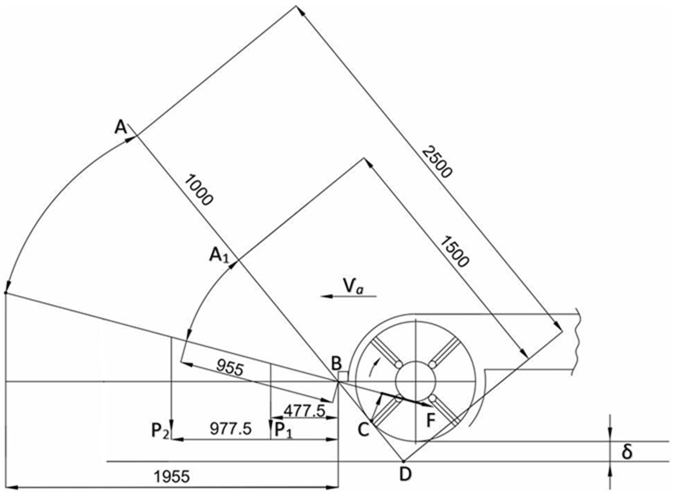
To clarify the rationale behind this recommendation, a conceptual model illustrating the mowing process of plants with varying stem heights by a single-rotor forage harvester is presented (
Figure 1).
The figure illustrates the process of mowing stalks with heights of 1.5 m and 2.5 m. Line A1D represents the mowing trajectory of a 1.5 m tall stalk as it encounters the cutting blades. Initially, the stalk is cut at point C and captured by the L-shaped blade, then rotated upward relative to the front bar, i.e., around point B. Under the influence of centrifugal force (F), the stalk is directed into the mowing rotor chamber. After rotating around point B, the stalk is cut a second time. These technological processes of stalk fragmentation have been described in previous studies [
21]. The resulting stalk particle lengths were measured as follows: BC = 0.208 m; CD = 0.337 m; BD = 0.545 m. This shows that the lower part of the stalk with a length of 0.545 m is initially cut.
When mowing 1.5 m tall stalks (as indicated by line A1D in the diagram), the outer portion of the stalk extending beyond the mowing rotor chamber is 0.955 m long, and its center of gravity is located 0.477 m from the front bar. Before the next cut of the lower portion, the stalk continues to move toward the mowing rotor chamber due to the centrifugal force (F). The formula used to determine this velocity is provided in [
21].
In addition, the forward motion of the unit increases the stalk’s entry speed into the mowing rotor chamber. Therefore, it can be assumed that the outer portion of the stalk, measuring 0.955 m, can enter the rotor chamber freely before falling to the ground.
The figure also shows the position of the outer portion of a stalk with a height of 2.5 m. When the lower part of the stalk is mowed, the remaining outer portion is 0.1955 m, with its center of gravity located 0.977 m from the front bar. In this case, it is unlikely that a stalk nearly 2.0 m long can fully enter the mowing rotor chamber. Thus, mowing stalks taller than 1.5 m may result in significant losses.
To address this issue, we initiated the design of a compact dual-rotor forage harvester capable of performing two-level mowing of tall-stemmed crops.
Upon analyzing existing forage harvester designs and reviewing published studies, we found no existing design of a dual-rotor harvester capable of two-level mowing of tall stalks.
The design process began by ensuring that each rotor, operating independently, could mow and chop stalks shorter than 1.5 m. Based on this requirement, the installation height of the upper rotor’s horizontal axis was determined.
The upper rotor mows and chops the upper portion of the stalks located at heights above approximately 1.2–1.3 m. Assuming the average height of maize stalks is 2.5 m, each rotor is designed to mow and process a 1.25 m section of the stalk.
An important design factor is the distance between the vertical axes of the mowing rotors. An optimal distance must be maintained to ensure the upper portion of tall stalks is reliably mowed by the upper rotor. If the distance between rotor axes is too small, the stalks may miss the upper rotor, resulting in substantial harvesting losses.
Conversely, an excessively large distance between the vertical axes increases the overall mass and cost of the machine.
Therefore, theoretical studies were planned to determine the optimal value of this distance.
Following this, a structural and technological schematic, along with detailed engineering drawings, was developed for the manufacture of the forage harvester. This provided a graphical explanation of the proposed two-level mowing model and initiated the design process of a dual-rotor forage harvester intended to perform two-level mowing of tall-stemmed crop plants.
The validity of the proposed design model will be verified through laboratory and field tests assessing the mowing of tall-stemmed plants.
Moreover, the aforementioned distance ensures the optimal implementation of the two-level mowing process. Hence, we propose the term “technological distance” for the distance between the vertical axes of the two mowing rotors.
Another disadvantage of these trailed harvesters is that their average length of shredded particles does not meet zootechnical requirements.
To improve the quality of shredded forages, we propose orienting stalks to be fed into the shredding chamber.
The results of theoretical and experimental studies have shown the efficiency of the orienting device [
21].
Mowing tall stalks with trailed combines is a challenging task. For this reason, we propose a design and technological scheme of a harvester that ensures the two-level mowing of tall stalks (
Figure 2).
The harvester is attached to a tractor, the drive gear train (11) is connected by a universal joint to the PTO of the tractor, and a cart is attached behind the harvester to load the shredded mass.
When the harvester is working, the front bar of the upper mowing rotor inclines the corn stalks, and at a certain inclination the stalks are shredded by the rotating knives of the upper mowing rotor. The upper part of the stalks is mowed, and the mowed upper part of the stalks is engaged by the knives, partially shredded, and fed through the upper channel to the screw chamber.
As the machine moves, the lower part of the stalks is mowed by the lower rotor and also fed into the screw chamber. Further, the mowed and pre-shredded mass is fed by the screw to the orienting drum. The blades of the orienting drum move the mass to the center and the drum compresses it, i.e., the fed mass is oriented along its length in the horizontal and vertical planes. The length-oriented stalks are cut, falling between the rotor knives and the contra-cutting plate. The shredded mass is then discharged by the shredding rotor blades into the deflector and then into the vehicle body.
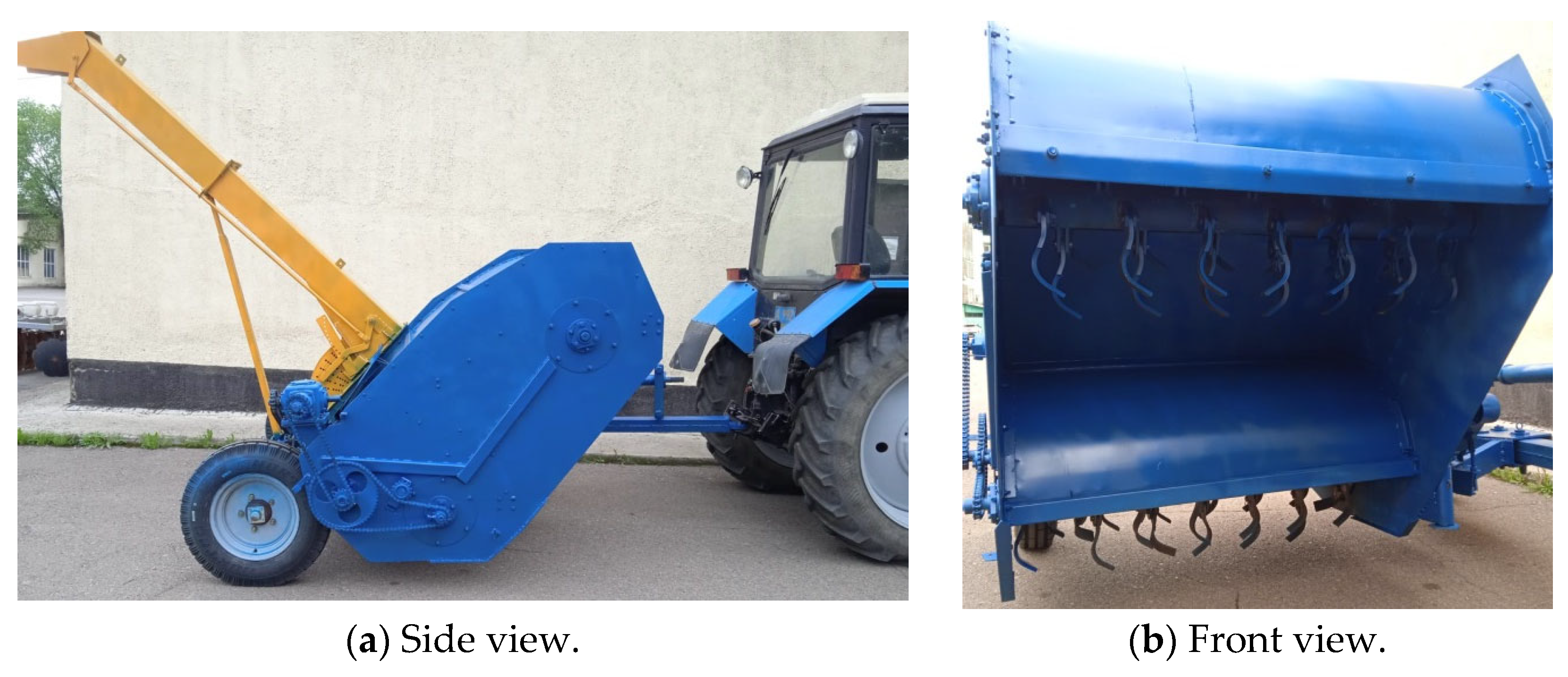
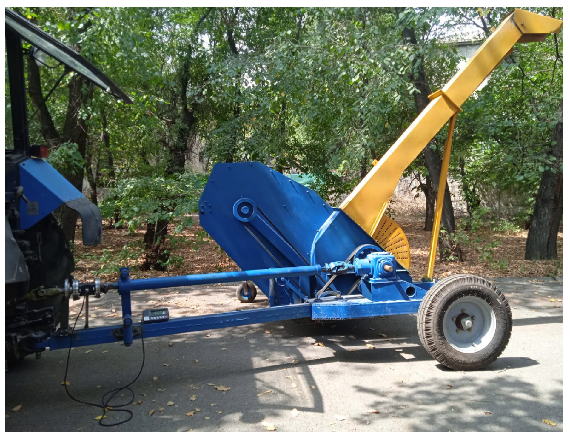
Grant funding was provided by the Science Committee of the Ministry of Science and Higher Education of the Republic of Kazakhstan, No. 286/23-25, dated 3 August 2023 (Grant No. AP19676816 Development of Compact Forage Harvester Equipped with a Device Orienting on The Length of Stalks). The first prototype of the forage harvester equipped with two mowing rotors and an orienting device was developed and manufactured according to the developed design and technological scheme (
Figure 3).
The technological distance between the vertical axes of the rotors is determined. The location of the upper mowing rotor is determined by two parameters. The first is the location of the horizontal axis relative to the ground surface. In this case, the height should be determined taking into account that the upper mowing rotor cuts half of the stem height, and the installation height of the horizontal axis h
0 is determined by the following formula:
where
Lc—the average value of stalk height during maize silage harvesting, m;
R—the mowing rotor radius at the ends of the blades, m.
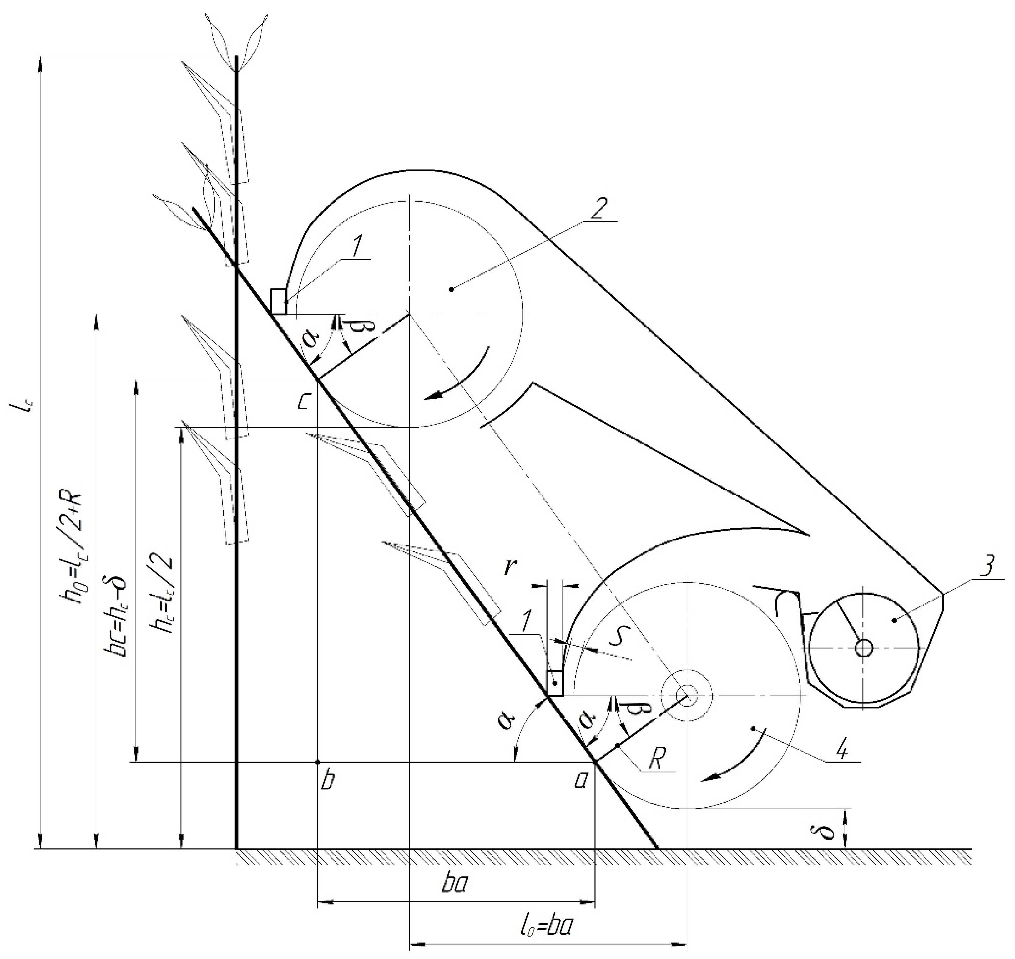
When determining the technological distance between the vertical axes of the mowing rotors, a potential critical position of the stalk was taken into account, in which a stalk may simultaneously come into contact with two mowing rotors (
Figure 4).
Figure 4 shows the simultaneous meeting of the stem with the blades of two rotors. This process can occur when the stem takes a position tangential to the circle of rotation of the two rotors. Here, the angle between the stem and the horizontal axes of the rotors is determined by the following formula:
where
R—the mowing rotor radius, m;
S—the gap between mowing rotor circles and rotor bodies, m;
r—the thickness of the front bar, m.
The peculiarity of this stalk position lies in the fact that at a smaller angle α, the stalk always comes under the impact of the upper rotor, increasing the length of side ab in triangle abc. As seen from the diagram, side ab is equal to the distance between the vertical axes of the rotors l0 (ab = l0).
Thus, with a greater distance of ab or l0 and a smaller angle α than indicated in the diagram, the stalks will always come under the impact of the upper blade. Conversely, with a larger angle α and a smaller length of side ab or l0, the stalk will come under the impact of the lower rotor. In this case, the upper rotor will not actually work, highlighting the importance of accurately determining the distance between the vertical axes of the two rotors.
Based on the above-mentioned, considering the triangle abc, we can determine the value of the length of the side of the triangle ab or the distance between the vertical axes of the two rotors. In this case, the distance between the vertical axes of the two rotors is calculated using a formula.
Therefore, to determine the technological distance between the vertical axes of the mowing rotors, the following expression was derived:
where
h—the stalk height cut by the upper rotor, m;
Lc—the average stalk height, m;
δ—the stalk height cut by the lower rotor, m.
In this case, to determine the technological distance, there is a need to determine the average height of corn stalks during their harvesting for silage. Therefore, we conducted special measurements to determine the physical and mechanical characteristics of corn stalks during their milk–wax ripeness [
14]. The results of the measurements revealed that the average height of corn stalks was equal to 2.4 m.
Taking into account the average height of corn stalks and using formula (3), the following parameters of the forage harvester were determined: δ = 0.15 m; R = 0.285 m; S = 0.015 m; r = 0.04 m. In addition, the technological distance between the vertical axes of rotors l0 ≥ 0.6818 m was calculated.
Therefore, the following expression is obtained to determine the technological distance between the vertical axes of the mowing rotors:
Using this formula, the actual value is defined: l0 = 0.7 m.
Consequently, to determine the optimal value of the distance between the vertical axes of the two rotors, i.e., the technological distance, an analytical expression was obtained that takes into account the parameters of the forage harvester and stalks.
4.2. Determination of the Required Power of the Feeding Screw and the Orienting Drum
When developing a new forage harvester that provides two-level mowing of tall stalks, equipped with a device orienting the length of stalks at the entrance to the shredding rotor chamber, at the initial stage it is necessary to conduct laboratory field tests to determine the performance and required power of the harvester units, i.e., to identify the energy assessment of the main units of the forage harvester.
When conducting laboratory field tests, it is possible to individually determine the required power for idling the machine and for mowing stalks, as well as for the total required power of the harvester when mowing grasses and tall corn stalks. In this case, it is extremely difficult to experimentally determine the required power for the operation of the screw and the orienting drum separately. Therefore, for the general energy assessment of harvester performance, we carried out a theoretical determination of the required powers for the working processes of mass feed by the screw conveyor and the orienting drum into the shredding rotor chamber.
The existing analytical expressions are intended to define the required power for the performance of the screw working device when moving bulk materials, i.e., the application of these expressions is associated with the determination of many coefficients. In addition, the work of the screw working device relates to the work of the mowing rotor. For this reason, we carried out a theoretical determination of the required power for the performance of the screw when feeding the mass to the orienting drum.
Only the lower mowing rotor works during mowing grass and picking up hay from the windrow. The upper mowing rotor only works when mowing tall stalks of crop plants (
Figure 4).
In this case, the harvester productivity during grass mowing is calculated by the following formula:
where
m—the mass of grass per 1 m2, kg/m2;
B—the cutting width of the mowing rotor, m;
υa—the machine velocity, m/s.
As illustrated in
Figure 4, the mown mass enters the screw chamber from above and is engaged by the screw blades. At the same time, the mass gains a velocity equal to the linear velocity of the screw blade. Then, the mass moves along the screw body. In this case, the velocity of mass movement in the screw chamber
υm is calculated by the following formula:
where
Sm—the screw blade pitch, m;
t1—the time for one screw rotation, s;
n—the screw speed, rpm.
Now, we define how long it takes to release the screw chamber from the incoming mass:
where
In the harvesting process, the mass continuously enters the screw chamber and is released during the time
t0. The value of the mass entering the screw chamber at time
t0 is calculated according to the following formula:
Now, the mass distribution along the length of the screw (linear mass) is determined:
According to the design, it is known that half of the screw blade will be on one side of the screw rotation circle. The mass coming from above is engaged by the screw blades, and at the initial stage the screw blades do not encounter great resistance. At the moment of moving the mass along the horizontal section of the bottom of the screw body, the blades experience great resistance. This is due to the fact that the mass moves at a speed equal to the peripheral speed of the screw blades.
In this case, the value of the mass to be engaged by one half of the screw blade is calculated by the following formula:
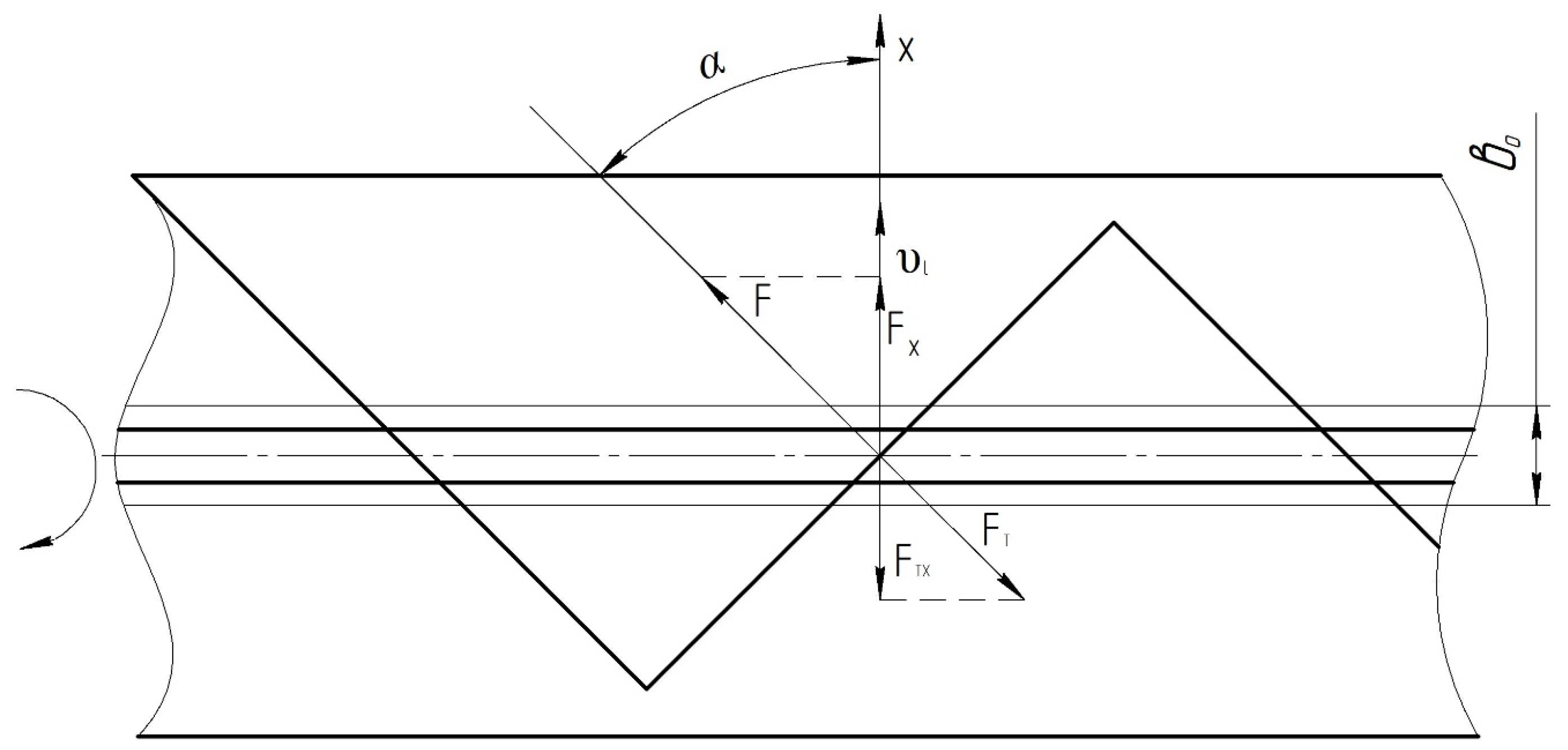
In the horizontal section of the bottom of the screw body, force
F is applied on the mass to be engaged on the side of the blade, and the blades encounter a great resistance on the side of the mass equal to the friction force (
Figure 5).
The screw blades encounter great resistance when moving the mass over a distance of . This is due to the fact that when the mass is lifted along the side wall of the screw chamber, the mass starts moving along the chamber, and in this case the resistance of the mass is reduced, so we can consider that the screw blades experience a great resistance in the section of mass movement at a distance of .
It should be noted that the mown mass flows along the entire length of the screw and along the outer side wall. The screw blades pick up the mass and guide it down the wall from the top to the bottom of the screw.
In this case, in the course of the circular movement of the mass in the first half of the screw blade bottom, it can be considered that the screw blades do not experience great resistance. This is confirmed by the fact that if the direction of shaft rotation is clockwise, the movement of the transported mass is carried out in the third quarter of the screw blade rotation circle.
From the course of physics, it is known that when a body moves, if external forces act on it, then the following condition must be met [
23]:
where
—the final and initial kinetic energies of a body, N·m;
A1 and A2—the work performed by external forces, N·m.
Herein,
It should be noted that the initial kinetic energy is equal to zero. This is due to the fact that when the mass is engaged by the screw blade, it first loses its velocity and instantly gains a velocity equal to the peripheral velocity of the screw blade υl.
That is why the equality of the change in kinetic energy considering the work performed by external forces can be given in the following form:
From here, we determine the value of the force acting on the screw blades:
In this case, formula (13) determines the value of force per blade, and taking into account the simultaneously working blades, the analogous expression has the following form:
The required power for the working process of the screw is calculated by the following formula:
Substituting the values
and
into formula (15), we obtain
where
In this way, taking into account the output of the machine and the kinematic modes of the screw, an analytical expression for determining the required power for the process of moving the mass by the screw working device is obtained.
4.3. Determination of Required Power for the Process of Stalk Orientation upon Entrance to the Chamber of the Shredding Rotor
The mass is moved in the screw body, fed to the orienting drum, and engaged by its blades. The stalk mass is oriented along its length and fed to the shredding rotor.
It is known that each row of blades engages a separate portion of the moved mass. Depending on the drum speed, it takes time for each row of blades to engage the mass:
where
—the speed of the orienting drum, rpm;
K—the number of blade rows along the drum periphery, pcs.
Within the defined time, the screw moves the mass over the distance
:
Depending on the linear mass distributed along the length of the screw, we determine the value of the fed mass located at section
, i.e., we define the value of the mass to be engaged by one row of drum blades.
As the mass is engaged by the blades of the drum, it experiences great resistance as it moves the mass along the bottom of the screw body.
Our laboratory experiments demonstrated that at the initial stage, the drum blades rotate the mass relative to the center of the fed mass, i.e., relative to the OS radius (
Figure 6).
In order to define the required power for the orienting drum, we will also consider the change in kinetic energy of the discarded mass by the drum blades.
When the mass engaged by the drum blade, the screw-driven mass losses its velocity, and when the blade rotates in the third quarter of the drum periphery, it experiences great resistance from the moving mass.
This resistance will continue until the radius of the mass center of gravity rotates by an angle β1 equal to 38°. It is known that when the steel plate is inclined by 38°, the stalk mass starts moving downward regardless of its moisture content.
At this angle of mass rotation, the blades will move through the mass without experiencing significant resistance, ensuring the further rotation of the mass’s center of gravity. This is related to the fact that, as the angle β decreases, the tangential component of the force increases, promoting the sliding of the mass along the drum blade.
That is why we will assume that the drum blades undertake the maximum work when the center of gravity of the mass moves to the distance DC.
It is necessary to determine the value of this distance Se.
The radius of rotation of the center of gravity of the mass is calculated by the following formula:
where
b0—the width of the horizontal section of the screw body, m;
d—the drum blade length, m;
β—the angle of inclination of the orienting drum screw blade from the horizontal axis of the screw.
At a small angle of rotation of radius
R by the angle
φ, the value of the length of the path of movement of the center of gravity of the mass
can be calculated by the following formula:
During the working process, the blade motion takes place along the horizontal axis X. That is why we will project the force acting on the mass from the blade side P, as well as the friction force PT on the X axis.
According to the design of the orienting drum, the angle
β = 45°, and as noted earlier,
β = 38°, i.e., the angle = 7°. Also, due to the small value of change in angles
β and
β1, the direction of line CD is taken as perpendicular to the radius of rotation of the mass at its angle of inclination equal to
. For this reason, the value
γ is calculated by the following formula:
Taking into account the change in kinetic energy of the mass supplied by the drum blades and the projections of forces
P and
Pт on the X axis, it is possible to write the equation of equality of kinetic energy with regard to the work of forces
P and
Pт:
Hence, we determine the mass resistance force on the drum blades:
By expressing the value
through the productivity of the machine, we obtain
where
In fact, each blade actually catches the mass
. Substituting the full value
into formula (24), we consider the simultaneous performance of two blades and express the linear velocity of the drum through its speed. So, the total required power of the orienting drum is calculated by the following formula:
where
An analytical expression for determining the required power for the process of stalk orientation at the entrance to the shredding chamber has been obtained.
4.4. Conducting Laboratory Field Tests to Determine the Required Power for Mowing and Stalk Forage Shredding Processes, and Defining the Required Power of the Forage Harvester Units
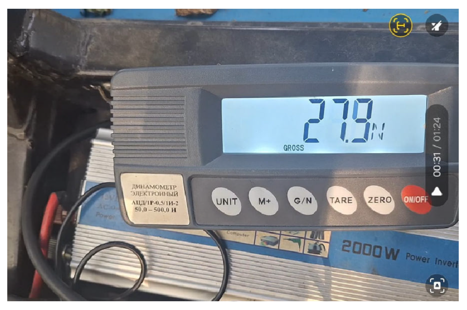
Laboratory field tests were carried out to determine the power balance by units of the forage harvester, as well as its performance in mowing tall corn stalks. The registration of required powers was carried out with a load cell TRK-50 and an electronic dynamometer ATSD-1R-0.5 (
Figure 7).
In order to determine the required power of the combine harvester, tests on mowing lucerne were conducted.
At first, we conducted experiments to determine the mass of lucerne from one square meter of lucerne field area. The average value of lucerne mass from 1 m2 was 1.006 kg/m2 ≈ 1.0 kg/m2.
The velocity of machine movement of υa = 0.83 m/s was chosen for the experiments. In this case, the power measurement was carried out while the machine was moving at a distance of 50 m. The experiments were repeated three times.
The value of required power for the idle running of the working devices of the harvester at the PTO speed of the tractor of 850 min
−1 was determined, and all the experiments were carried out at this operating mode of the harvester. This is due to the fact that all forage harvesting field work is carried out at medium engine speed. In this case, the idle power was equal to
Nxx = 2.45 kW (
Figure 8).
The required power of the harvester for mowing lucerne was determined using the developed program (
Figure 9).
The productivity of the harvester while mowing lucerne was equal to Q = 1.12 kg/s = 4.03 t/h. The total power input was equal to NO = 9.78 kW.
It should be noted that during the harvesting of grass and low-growing plants, only the lower rotor is in operation. This is because, at the time of forage grass harvesting within the agrotechnical window, the plant stem height typically ranges from 0.6 to 0.65 m. In such cases, the front bar of the lower mowing rotor is positioned at a height of approximately 0.4 to 0.45 m.
As the unit moves forward, the front bar merely bends the upper leafy portion of the grass, which then immediately enters the mowing rotor chamber and is captured by the cutting blades.
Field observations of the harvester’s operation during mowing confirmed that the machine functioned without disrupting the technological process and without incurring losses. This confirms the validity of the stated assumption.
Further, experiments were conducted to determine the required power for the process of mowing lucerne only.
For mowing lucerne only, the screw cover was opened, and an additional cover was placed on top of the screw body. This ensured discharge of the mowed mass directly to the swath. Therefore, the required power for grass mowing only was determined (
Figure 10).
In these experiments, the average required power for mowing lucerne was NK = 3.7 kW, and the average required power for the mowing process without idling was NK = 1.25 kW.
In order to determine the total power balance, the required power for the processes of mass transportation by the screw working device and the orienting drum into the chamber of the shredding rotor was determined by the obtained analytical expressions.
At the pitch of the blade screw of Sm = 0.28 m and a speed of n = 306 rpm, the speed of mass movement along the length of the screw was equal to = 1.428 m/s. Here, the screw length = 0.817 m, and at the speed of mass movement along the screw, its body is released in the time tO = 0.572 s.
At the harvester productivity Q = 1.12 kg/s (Q = 4.03 t/h), 0.64 kg of mowed mass enters the screw chamber during the time tO. This mass will be distributed along the length of the screw and the linear mass my = 0.7834 kg/m.
At the beginning, we determined the resistance encountered by one half of the screw blade on the side of the engaged mass = 0.11 kg, i.e., one pitch of the screw blade engages 0.11 kg of mowed mass.
The distance at which the screw blades encounter maximum resistance when the mass is moving is also important for the calculation. It is known that screw blades encounter great resistance at the bottom of the screw body. In this case, the length of the horizontal section at the bottom of the screw is 0.1 m.
Considering that the mass enters from above along the outer side wall of the screw, it may be considered that the screw blades encounter resistance in the second half of the screw bottom, so m.
At a screw radius of 0.14 m, the peripheral velocity at the ends of the screw blades was = 4.484 m/s and the angle of inclination from the horizontal axis at the ends of the blades was 45°; consequently, cos 45° = 0.7071.
Special experiments revealed that stalk forage at the angle of the steel plate of 38° began to roll down; consequently, f = 0.78.
The experiments were conducted on chopped lucerne with a moisture content of 72.58% and on chopped maize stalks with a moisture content of 72.38%.
This high moisture content was chosen because the forage harvester is mainly designed for harvesting green mass, haylage, and corn silage.
In this case, the lucerne and maize stalks used for the experiment were chopped by the forage harvester.
During the experiments, these chopped stalks of lucerne and maize were rolled down at an angle of inclination of the steel plate of 37–39°; i.e., the average value of the angle of inclination of the stalks was 38°. From here, it is known that tan38° = 0.78; i.e., the friction coefficient of pre-shredded lucerne and corn stalks f = 0.78.
With the values of the parameters mentioned above, the calculation of formula (26) showed that = 0.42 kW.
The following parameters included in formula (26) were also established and were equal to Q = 1.12 kg/s; = 0.16 m; = 170 rpm; K = 4; and f = 0.78.
Taking into account the known values of the parameters included in formula (26), the value of the required power for the process of the orientation of the stalks at the entrance to the chamber of the shredding radial cutting and bladed rotor was determined: Nδ = 0.11 kW.
These calculated values of screw and drum required power were determined at average values of productivity of Q = 4.03 t/h. In addition, for more productive horizontal screw conveyors, drive motors should be installed with a capacity of 1.1–1.5 kW. That is why the obtained theoretical values of power can be considered close to a reliable result.
On this basis, it was possible to identify the distribution of the required power by units of the forage harvester (
Table 1).
The balance of the forage harvester required power shows that 75% of the power is used for the full performance of the harvester. As the productivity of the machine increases, the share of power for full performance should increase. All this indicates that the harvester has a high efficiency in carrying out technological processes.
The technological distance between the vertical axes of the mowing rotors was determined during the development of the drawing documentation for the harvester.
Using the average stalk height and the analytical expressions obtained, the technological distance of l0 = 676 mm was defined. That is why the value of l0 = 700 mm was accepted in the drawing documentation.
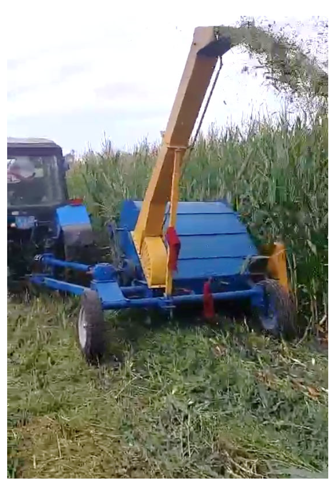
Laboratory field tests of the harvester were conducted on the corn field at “Aydarbayev E” farm, where the average height of corn stalks was 2.9 m.
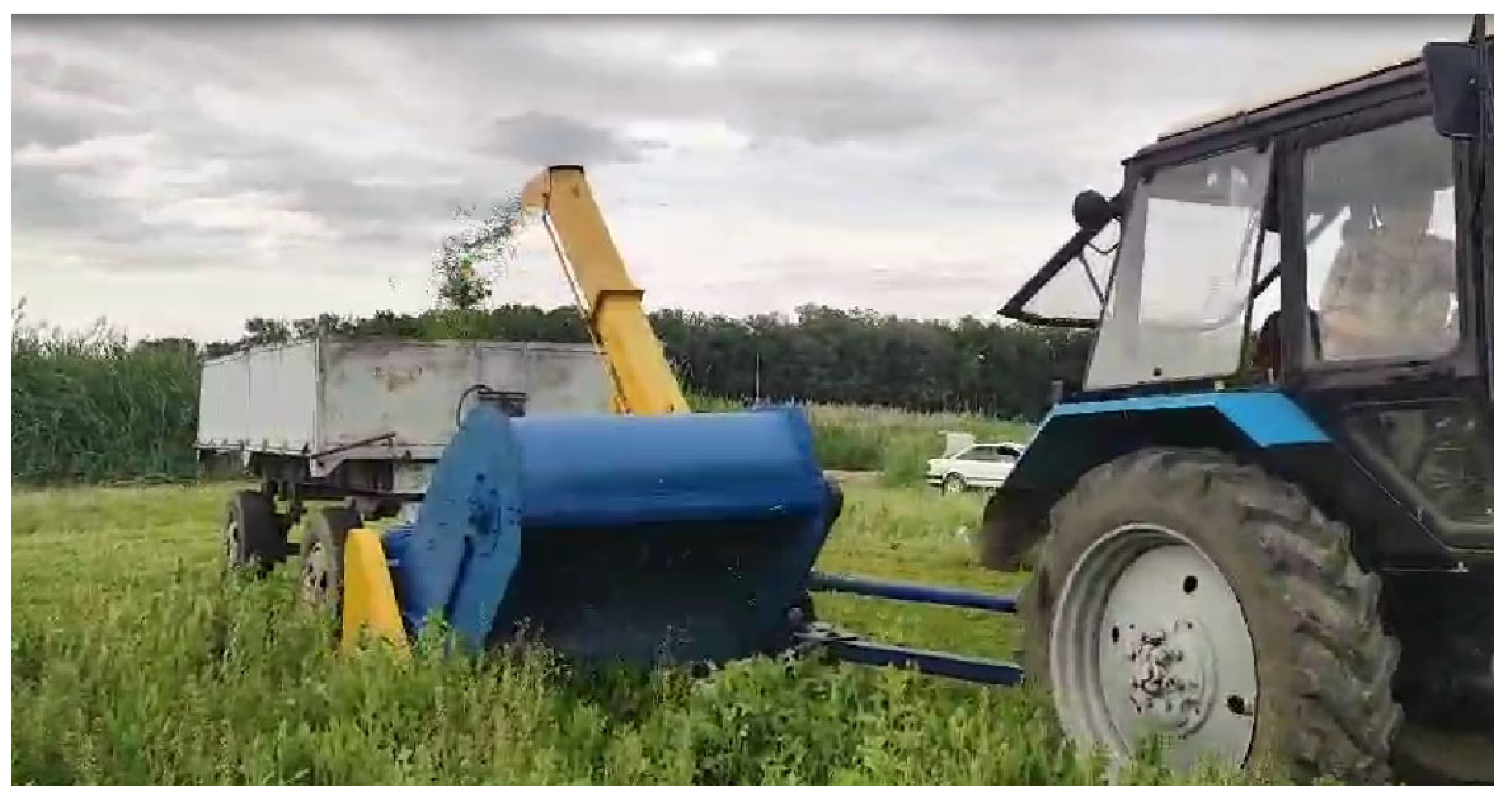
To validate the performance of the top mowing rotor, experiments were carried out in a corn field. The moisture content of the mass amounted to 72.38%. It should be noted that the lower part of the corn stalks was dry, with a humidity of 16–18%, and corn cobs were harvested earlier. Experiments were carried out at different speeds and the required power was measured. For this purpose, the speed of the machine during each experiment and the mass of shredded corn stalks were determined (
Figure 11).
The results of the harvester’s performance are presented in
Table 2.
The results given in the table demonstrate that, at all the above-mentioned speeds, the combine harvester performed the mowing and shredding of tall corn stalks without violating the technological process. In this case, at a machine speed of 0.91 m/s, corn stalk losses amounted to 3.0%, which is acceptable for forage harvesters.
The results of the third experiment demonstrate that the specified mode of the work is higher than the optimum productivity of the harvester. It should be noted that the harvester performed without violation of the technological process.
The results of the experimental studies also confirm the reliability of the proposed graphical model for single-rotor mowing and for theoretical investigations related to the two-level mowing of tall-stemmed crops.
In this case, experiments on mowing tall maize stalks were conducted at various forward speeds of the machine, ranging from 0.67 to 0.91 m/s. At the beginning of the field trials, different travel speeds were selected to assess the harvester’s operational feasibility. For instance, in [
16], a speed of 1.0 m/s was identified as the optimal forward speed for a trailed forage harvester.
In reality, the speed of the machine is selected depending on the type of plants to be mown and their yield.
There are recommendations in the literature for selecting machine speeds for trailed combines:
- -
When working with high-yielding and wet forage (e.g., maize for silage)—0.42–0.83 m/s (1.5–3.0 km/h);
- -
When harvesting hay or less dense mass—0.83–1.39 m/s (3.0–5.0 km/h);
- -
When working in light conditions (dry mass, flat terrain, low grass)—up to 1.67 m/s (up to 6.0 km/h) [
24,
25].
Hence, it can be seen that the selected speeds of the machine correspond to the recommendations for mowing high-yielding maize stalks.
For the field experiments, the circumferential speeds of the mowing and chopping rotors were selected in accordance with the circumferential speeds of the cutting drums, as well as the mowing and chopping rotors of existing forage harvesters.
For example, the following forage harvesters have cutting drums with circumferential speed as detailed: Jaguar-830 Claas—39.56 m/s; FX 307 New Holland—39.23 m/s; BiGXV12, Krone—37.99 m/s. Hence, it can be seen that in existing forage harvesters, the circumferential speeds of cutting drums are within 37.99–39.56 [
13]. In addition, the circumferential speeds of mowing and chopping rotors of trailed forage harvesters are within 35–40 m/s [
15].
Thus, the above-mentioned circumferential speeds of chopping and mowing working bodies provide mowing and chopping of all types of grasses and plants, including high-growing and wet crops, at permissible energy consumption and minimum losses.
Therefore, the same tractor engine speed was set in all field trials, regardless of the speed of the machine. In this case, the tractor PTO speed and the rotational speed of the blade chopping rotor were equal to 850 rpm (linear speed of radial knives—35.6 m/s), and the rotational speed of the mowing rotors was 1250 rpm (linear speed of knives—36.9 m/s).
Therefore, in the field experiments, the cutting speeds of the mowing and chopping rotors were set at the same level and were equal to the circumferential speeds of the chopping drums and rotors of existing machines.
The speed of mass feeding by the orienting drum into the chamber of the shredding rotor also had a constant value.
At the speed of rotation of the orienting drum of 170 rpm, with a diameter at the ends of the feeding fingers of 0.32 m, the speed of mass feeding was equal to 2.85 m/s.
This speed of mass feeding into the chamber of the chopping rotor provided the calculated cutting length of 34.9 mm, and the actual value of the cutting length when mowing and chopping lucerne was 33.79 mm [
21], which corresponds to the expected cutting length of stem forage for feeding sheep and cattle.
Therefore, the selected operating mode of the forage harvester in terms of cutting speed and mass feeding into the chamber of the chopping rotor provided the expected cutting length and ensured the quality of chopped fodder corresponding to zootechnical requirements (the average cutting length of chopped particles for sheep and cattle should be within 30–50 mm).
Regarding the cutting length of maize stalks given in
Table 2, it can be noted that the lower part of the stalks had low moisture, and the stalks were chopped by breaking, so these stalks had a larger cutting length.
It is clear that when making silage, the moisture content of maize stalks along their length has the same value, and they are well cut by the knives of mowing and chopping rotors. Therefore, the average length of the chopped particles should be close to the calculated cutting length of the stalks.
Moreover, the mowing rotor demonstrates effective performance in cutting grass regardless of lodging conditions. This is evident from the harvester’s loss-free operation while mowing maize stalks up to 2.9 m in height.
It is also necessary to note that tall corn stalks are not suitable for harvesting corn silage. According to the requirements, silage harvesting should be carried out at milk–wax ripeness, when the moisture content of the mass is more than 80%. Under these conditions, corn stalks are much easier to mow and shred. The shredding quality has to be much better than that presented in the table.
It is significant that these experiments established the performance of the harvester under harsh conditions.
In summary, the results of the above-mentioned experimental studies prove the reliability of theoretical research on the technological distance between the vertical axes of mowing rotors and the design and technological scheme of the harvester, as well as the performance of the orienting drum and other units of the harvester.


 ,
, 


