1. Introduction
Composite materials, predominantly composed of resins and fibers, exhibit a significantly lower electrical conductivity compared to metallic counterparts such as aluminum alloys [
1]. This inherent characteristic renders composite aircraft more susceptible to the adverse effects of lightning strikes. When subjected to a lightning event, the surface structure of composite aircraft can suffer from severe damage, including ablation, perforation, delamination, and fiber breakage [
2,
3]. These types of damage are not only detrimental to the aerodynamic profile of the aircraft but also have the potential to compromise its structural integrity, posing a latent threat to flight performance and safety [
4]. In the context of addressing minor lightning-induced ablation damage, a prevalent repair methodology involves the application of patches fabricated from the same composite material as the original [
5]. This approach aims to restore the integrity and functionality of the affected area without necessitating the replacement of broader structural components.
Although the patch repair method utilizing materials identical to the original structure in the aviation field can partially restore structural damage caused by lightning strikes, the effectiveness of such repairs is constrained by various factors. Current research has elucidated certain limitations within the field, providing a foundation for further investigation. Firstly, even when employing identical materials for repair, the structural integrity and mechanical properties of the repaired area are often difficult to restore to their original levels [
6,
7,
8]. More critically, the material utilized for damage repair may introduce interphase discrepancies when bonded with the original material, leading to a decline in electrical and thermal conductivity [
9]. This not only potentially compromises the repaired structure’s resistance to lightning strikes but also may result in more severe damage upon subsequent lightning encounters [
10]. Consequently, current repair techniques exhibit significant deficiencies in restoring the electro-thermal properties of composite materials. This poses further challenges for maintaining the long-term safety and functional integrity of aircraft. It necessitates an in-depth investigation that integrates a greater array of simulation and experimental methodologies.
Electro-thermal coupling simulation technology plays a pivotal role in mimicking the response of composite materials to lightning strike damage. This approach affords precise simulation of material damage under various operational conditions by concurrently modeling the flow of lightning currents in composite materials and the attendant thermal effects. The electro-thermal coupled finite element analysis model proposed by Ogasawara et al. [
11] has been extensively utilized to simulate the ablation damage of composites due to lightning strikes. This model employs the computed temperature fields to estimate the extent of lightning-induced damage and to characterize the electro-thermal response of the composite material to the electrical current. Shan et al. [
12] constructed a finite element model of curved laminates using the electro-thermal coupling analysis capabilities of the Abaqus software to investigate the impact of various factors on their lightning-induced damage performance. Furthermore, Abdelal et al. [
13] introduced alternative thermo-physical property parameters, such as the temperature-dependent dielectric constant, to simulate lightning damage and to further explore the damage mechanisms of laminates. Building upon the foundation of electro-thermal coupling, Dong et al. [
14] developed an electro-thermal–pyrolysis model that predicts the degree of resin pyrolysis through numerical analysis based on electro-thermal principles, thereby assessing the damage caused by lightning strikes.
Previous studies have addressed the reliability of composite material repairs using advanced simulation and experimental techniques, assessing and predicting the behavior of repaired composites upon subsequent lightning strikes, thereby laying the groundwork for improved repair strategies. Spencer et al. [
15] demonstrated through ultrasonic imaging that lightning-damaged regions exhibit material property changes, which may direct subsequent lightning strikes to the same or nearby locations. Sun et al. [
16] investigated the damage characteristics of CFRP composites under multiple consecutive lightning currents and found that the thermal effects and material property changes in these regions could increase the likelihood of subsequent strikes. Roche et al. [
17] demonstrated that infrared thermography can effectively monitor the extent of lightning-induced damage in composites. Yin et al. [
18] employed experimental and numerical nonlinear Lamb wave analysis to investigate the impact of patch size on the repair effectiveness of low-velocity impact damage in carbon fiber-reinforced polymer (CFRP) laminates. Wang et al. [
19] focused on evaluating damage after repetitive lightning strikes on aircraft structures, highlighting the utility of numerical simulations and residual strength testing in predicting and validating the mechanical integrity of repaired composites under various lightning conditions. Wolfrum et al. [
9] enhanced the conductivity of the adhesive layer with carbon nanotubes, mitigating the damage caused by internal discharge in composites and improving the efficacy of the repair. However, research on the lightning protection performance of repaired structures and the optimization of repair strategies remains limited. By examining the electrical and thermal protective capabilities of these coatings under repeated lightning strike conditions, this research aims to provide a deeper understanding of their effectiveness in enhancing the durability and performance of repaired structures.
This study developed an electro-thermal coupling model for composite laminates to simulate lightning strike damage under various peak current conditions. The composite materials mentioned in this study are primarily carbon fiber-reinforced polymer composites. Simulations compared the damage profiles of original and patch-repaired structures to assess the repair effectiveness. The study also optimized aluminum coating schemes, investigating how coating width and shape affect lightning protection. These findings provide a theoretical foundation, modeling approach, and technical support for evaluating the safety and reparability of structures after lightning strikes.
2. Electro-Thermal Modeling and Analysis of Composite Materials Under Lightning Strike
2.1. Mathematical Models
The electro-thermal coupling model is widely utilized for analyzing the electro-thermal effects induced by lightning currents passing through materials. This model primarily focuses on the transient heat transfer process following the impact of lightning currents on the laminate. It describes the phenomena of Joule heating, internal heat transfer within the material, and thermal exchange with the surroundings by controlling the governing equations, energy conservation equation, and boundary condition equation. Thus, it provides a comprehensive analytical framework for simulating and analyzing the electro-thermal effects of lightning strike on the laminate. The mathematical model reveals the laws of current path and heat transfer during lightning strike through a fully coupled electro-thermal process. Under specific thermal boundary conditions, the transient heat transfer analysis was conducted by applying the generated Joule heat to individual finite elements, ultimately obtaining the temperature field distribution of the laminate to evaluate the damage area. Specifically, three main behaviors occur during the lightning strike: (i) current conduction behavior; (ii) thermal conduction behavior; (iii) thermal exchange behavior. These are detailed as follows.
2.1.1. Electro-Thermal Coupling Governing Equations
When examining the impact of lightning strikes on materials, it is crucial to consider the thermal effects induced by electrical resistance. The electro-thermal coupling governing equations introduced in this section are fundamental for understanding charge conservation and thermal effects during the transmission of electric current through materials. This system of equations integrates the principles of electro-thermal conservation, encompassing Maxwell’s equations and Ohm’s law, to elucidate the distribution of electric current and the generation of thermal energy during lightning strikes.
Charge conservation is reflected in Maxwell’s equations, ensuring that the total charge in the system remains constant as lightning current penetrates and traverses the material. Assuming the current is a steady-state direct current, the equations simplify to
where V represents the volume of the unit cell, S denotes the surface area of the unit cell, n signifies the outward normal direction of S, J is the current density, and
represents the internal volume current per unit volume. When charged particles move in the direction of the electric field, their potential energy increases, necessitating that the direction of the electric potential gradient be opposite to that of the electric field. Consequently, employing Ohm’s law, the current density is derived as follows:
where the electric field E can be defined as the gradient of the electric potential
.
represents electrical conductivity. x represents the spatial coordinate along the x-axis. The rate of change of charge within a closed volume is equal to the difference between the current penetrating and the current traversing that volume. The relationship between the electric field and current density can be further analyzed using the chain rule and the divergence theorem as follows:
where
denotes an arbitrary variation in the electric potential field. Equation (
3) is used to describe the relationship between the electric potential field and the electric field density within a given region, incorporating contributions from both the volume and the boundaries.
2.1.2. Energy Conservation Equation
The energy conservation equation serves as the theoretical cornerstone for investigating the thermal conduction behavior of composite laminates under the action of lightning strikes. This equation comprehensively considers the mechanisms of internal energy transfer within the material, encompassing the Joule heating effect due to electrical resistance, the pyrolytic heat release at elevated temperatures, and the processes of heat conduction and accumulation within the material. It provides a foundational framework of the generation and dissipation pathways of thermal energy during lightning strike. The conversion of electrical energy into thermal energy as current flows through a conductor is governed by Joule’s law, which can be articulated as follows:
where
represents the power density generated per unit volume when current flows through an electric field. Drawing from the energy balance equation, the internal thermal conduction behavior within each laminate unit of the composite is delineated by the conservation of energy principle as follows:
where
represents the material density,
U denotes the material time rate of change of internal energy,
k is the thermal conductivity matrix, where the thermal conductivity matrix of the CFRP laminate is anisotropic, r represents the heat generated within the unit cell, and
q is the heat flux per unit area of the unit cell.
is an arbitrary variational field that satisfies the fundamental boundary conditions.
The energy released as an internal heat source is expressed as follows:
where
represents the energy conversion factor.
2.1.3. Boundary Condition Equation
The thermal exchange behavior between the surface of composite materials and their surrounding environment is described by the electro-thermal coupling boundary condition equation, involving parameters such as the convective heat transfer coefficient, radiation conditions, and ambient temperature. The top and side surfaces of laminates release a large amount of resistive heat abruptly due to the conduction of lightning current, resulting in significant temperature differences with the surrounding environment. Consequently, heat transfer to the surroundings is predominantly facilitated by thermal radiation, employing a third-type boundary condition as follows:
Due to the absorption or dissipation of lightning currents, primarily by the upper layers of the structure, the temperature variation at the bottom surface is minimal, and the temperature gradient with the surrounding environment approaches zero. This is primarily because lightning strikes typically involve high peak currents with short durations, causing the current and heat to be dissipated mainly in the surface layers. Additionally, the anisotropic thermal conductivity of composite materials further limits heat transfer to the bottom layers. Therefore, the thermal exchange effect at this interface can be negligibly small, warranting the adoption of second-type boundary conditions, which can be described as follows:
where
represents the surface temperature of the metallic shielding layer,
denotes the ambient temperature,
is the absolute zero value of the temperature scale,
is the surface heat flux density,
is the Stefan–Boltzmann radiation constant, and
is the contact thermal conductivity.
2.2. Finite Element Model
In the electro-thermal coupling model, interactions between different layers in the composite laminate are comprehensively considered. Each layer’s response to the electric field depends not only on its own conductivity properties (both longitudinal and transverse) but is also influenced by adjacent layers. At interfaces, electrical potential and current density are assumed to be continuous, implying no additional contact resistance. The model also accounts for temperature effects on material properties, where conductivity changes with local temperature, further affecting the electric field distribution and heat generation.
2.2.1. Mesh Generation and Boundary Condition
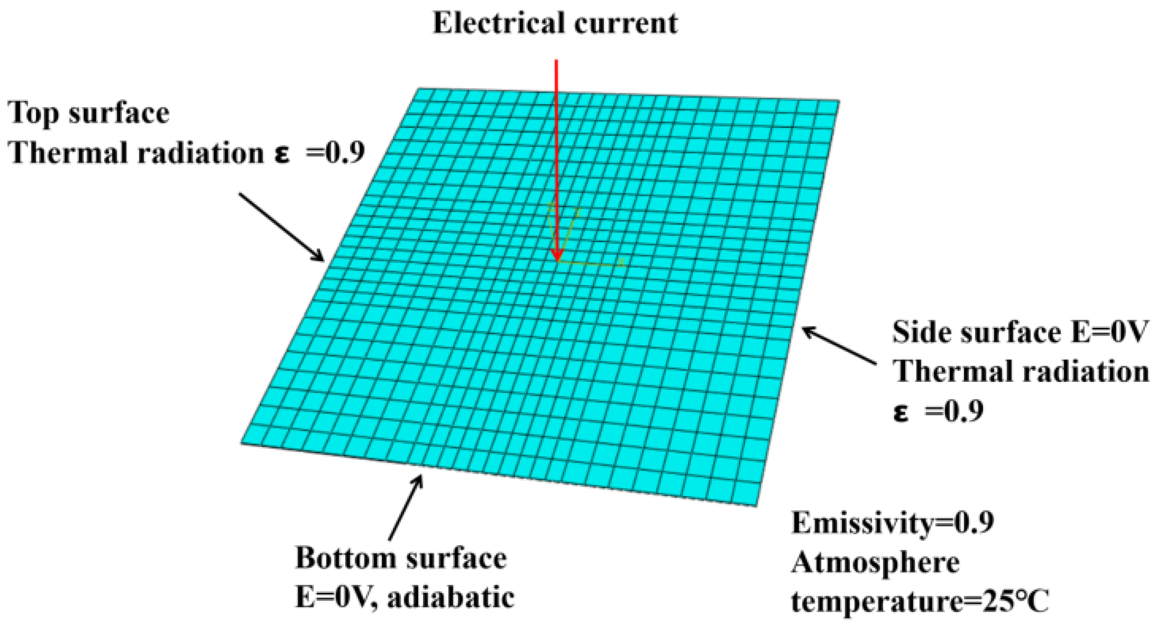
The composite laminate model established in this study measured 100 mm × 100 mm, with individual ply thicknesses of 0.2 mm and a layup sequence of [45/0/– 45/90]
2S, totaling 16 plies, as depicted in
Figure 1. The mesh was generated using DC3D8E elements, which are eight-node linear electro-thermal coupled hexahedral elements; a mesh convergence analysis was conducted by progressively refining the mesh density until the temperature field and damage area predictions stabilized. The optimal mesh size was determined when further refinement produced a less than 2% change in the predicted maximum temperature and damage area. An implicit solver (Abaqus/Standard) was used in the simulation. To enhance the simulation accuracy and precisely model local effects, the mesh was locally refined in the central region, resulting in a total of 33,728 elements. Based on the operating conditions described in the experiment, precise electrical and thermal boundary conditions were applied during the simulation. The side and bottom surfaces of the specimen were in full contact with the metal components of the experimental apparatus, ensuring effective grounding. Consequently, the electric potential for the side and bottom surfaces was set to 0 V. Due to Joule heating, significant temperature increases occurred along the current flow paths, leading to substantial temperature differences between the top and side surfaces and the environment. Therefore, a third-type boundary condition with a thermal emissivity of 0.9 was applied. The bottom surface of the laminate exhibited minimal temperature variation and was treated as adiabatic, employing a second-type boundary condition with the ambient temperature set to 25 °C, considering the short duration of lightning strikes and the limited heat diffusion to the bottom layer.
2.2.2. Material Properties and Damage Assessment Criteria
As a high-performance composite material, CFRP exhibits significant anisotropic behavior. Its electrical and thermal conductivities vary with fiber orientation (longitudinal and transverse) and through-the-thickness direction. In this study, a homogenization approach was employed, where the properties of fibers and epoxy resin were integrated into equivalent layer properties, rather than modeling each constituent separately. The temperature-dependent properties of the laminate, such as specific heat, density, and electrical conductivity, are crucial for accurately grasping the material’s thermal response characteristics under electro-thermal coupling conditions.
Table 1,
Table 2 and
Table 3 present the temperature-dependent material properties [
13,
20,
21,
22].
When assessing the lightning-induced damage in CFRP composites, the material’s phase transition behavior at specific temperatures significantly alters its physical properties, thereby influencing the distribution of heat within the material. Non-uniform thermal distribution can result in localized overheating and subsequent damage. Ogasawara et al. [
11] extensively investigated the behavior of carbon fibers and epoxy resin matrix in CFRP at various temperatures using thermogravimetric analysis (TGA), providing specific temperature thresholds for damage determination. When lightning strikes induce high temperatures, the thermal behavior of CFRP can be delineated into several critical stages: When the temperature rises to approximately 250–300 °C, resin begins to degrade thermally, causing localized ablation damage on the laminate. As the temperature continues to increase to about 600 °C, the resin undergoes complete thermal decomposition, leading to delamination within the laminate. Further temperature rise causes the resin to vaporize, while carbon fibers, exhibiting higher temperature resistance compared to the resin, decompose at approximately 3000 °C. Beyond this temperature, dielectric breakdown occurs at interlayer gaps, causing a sharp increase in through-thickness electrical conductivity. As carbon fibers fracture due to decomposition, Joule heating is prevented. Therefore, areas with temperatures exceeding 250 °C are considered to have experienced ablation damage due to the thermal degradation of epoxy resin.
2.2.3. Lightning Strike Current Load
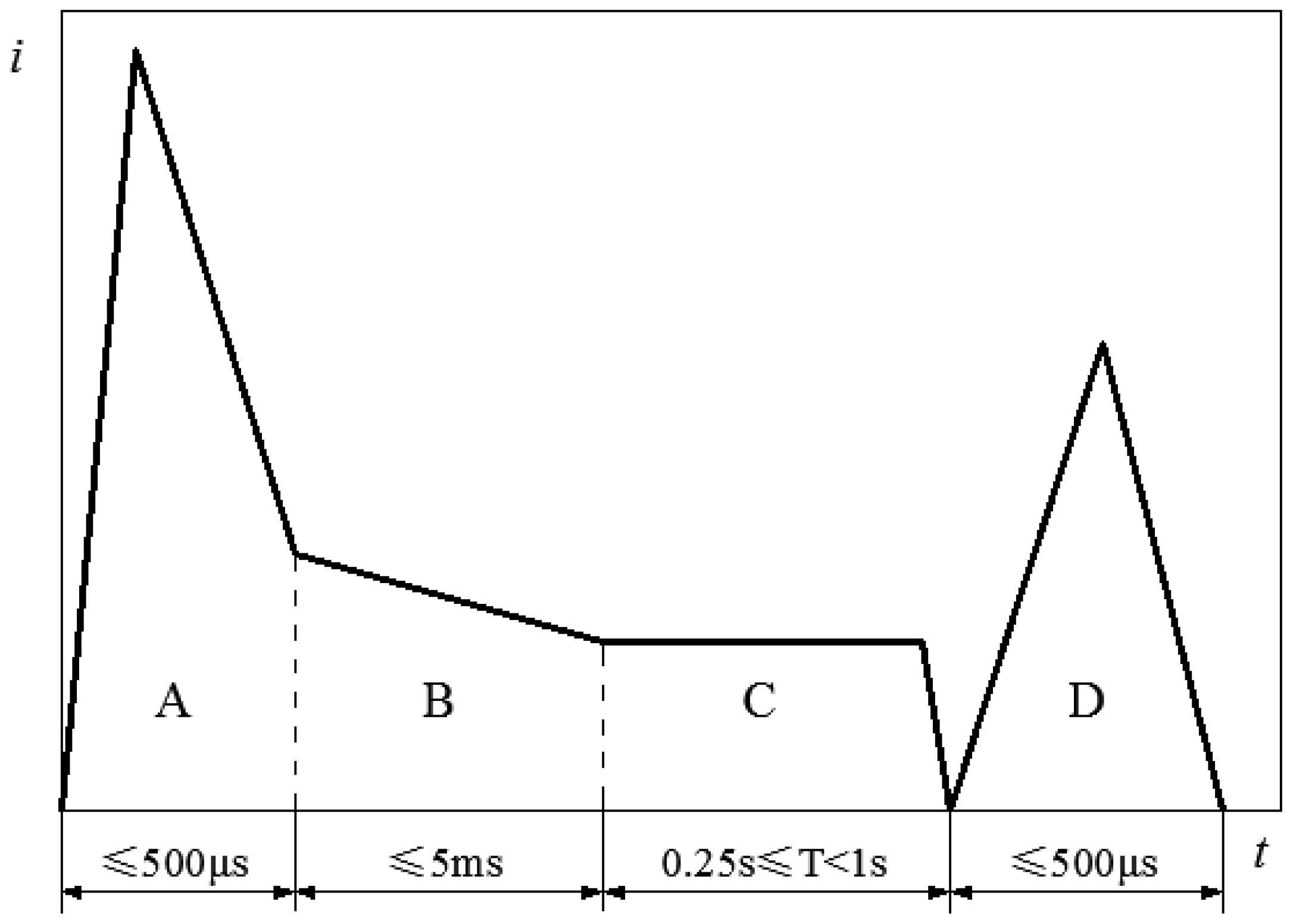
The Society of Automotive Engineers (SAE) has established a lightning current waveform standard that offers crucial guidance for simulating real-world lightning environments in laboratory settings. This standard delineates lightning currents into four distinct components—A, B, C, and D—as illustrated in
Figure 2 [
23].
Component A signifies the initial stage of a lightning strike, characterized by a rapid and substantial energy release with an extremely short duration, posing the most direct and destructive threat to laminates. The impulse amplitude of this component ranges from 10 to 200 kA. In simulated environments, the A waveform, which has the maximum energy and shortest duration, is typically utilized to simulate lightning current. It is marked by a prompt rise to peak amplitude followed by a prompt decline, behavior that can be characterized using a double-exponential function, as presented in Equation (
9).
where
is the lightning current,
is the effect factor of the double-exponential function,
and
are the frequency parameters of the double-exponential function, and
t is time.
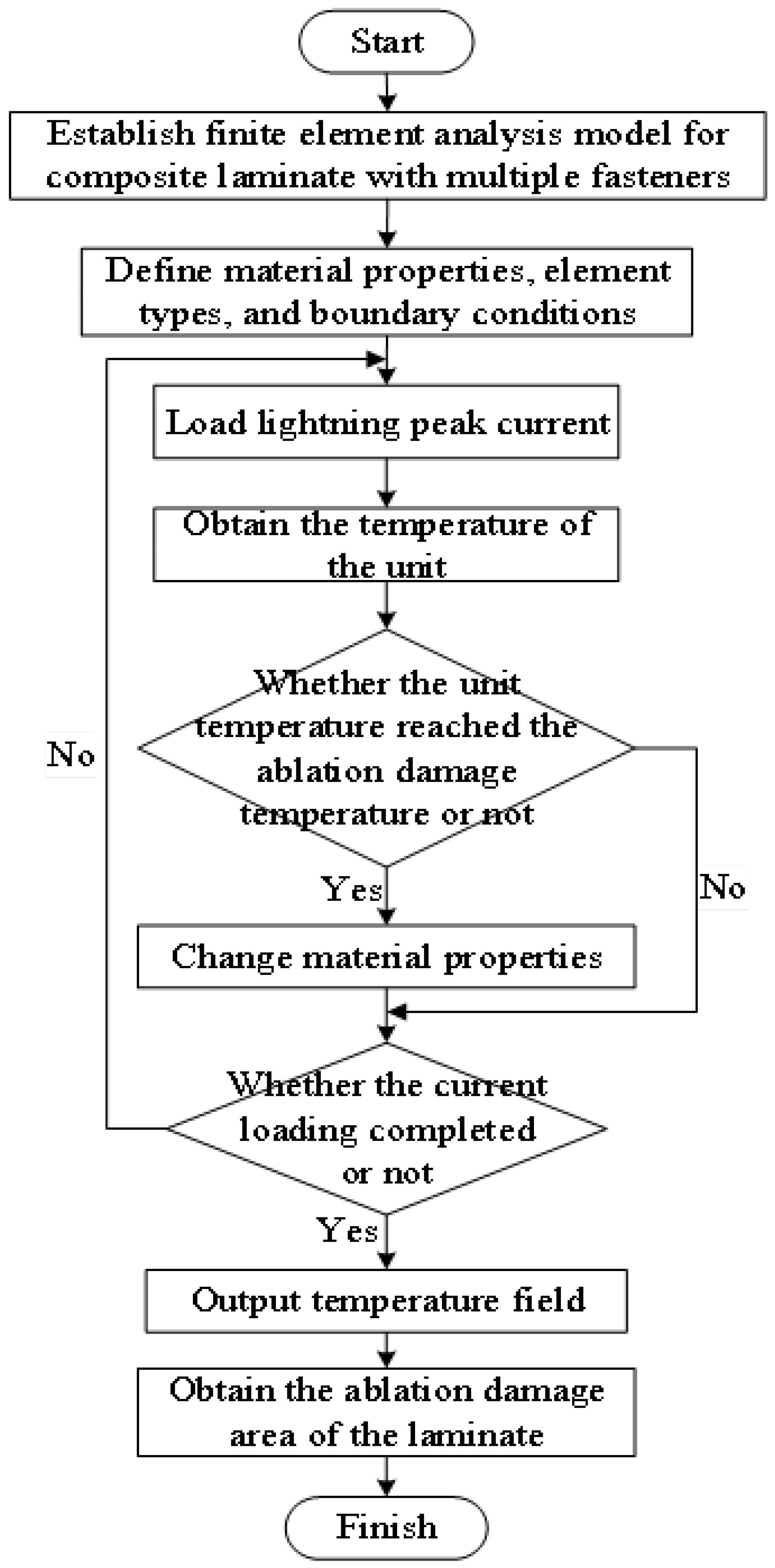
2.2.4. Key Processes of the Analysis Method
The electro-thermal coupling analysis method is a multiphysics simulation technique utilized to delineate the damage state of materials by simulating the temperature field distribution, thereby predicting the extent of damage and informing the design of repair measures. Lightning-induced damage is conducted using the Abaqus FEA software, as shown in
Figure 3. The detailed components of this analysis have been previously described in
Section 2, including mesh generation and boundary conditions (
Section 2.2.1), material properties (
Section 2.2.2), and current load (
Section 2.2.3). In the initial step, the potential subjected to lightning current is computed under prescribed electrical boundary conditions, while transient heat transfer is performed by applying the generated Joule heat to each finite element under given thermal boundary conditions. The analysis incorporates temperature-dependent material properties, with full coupling between electrical and thermal analyses. Phase changes due to temperature increases are monitored for ablation damage indicators. If an element reaches the critical temperature, its properties are adjusted; otherwise, they remain unchanged. The final temperature distribution identifies ablation areas.
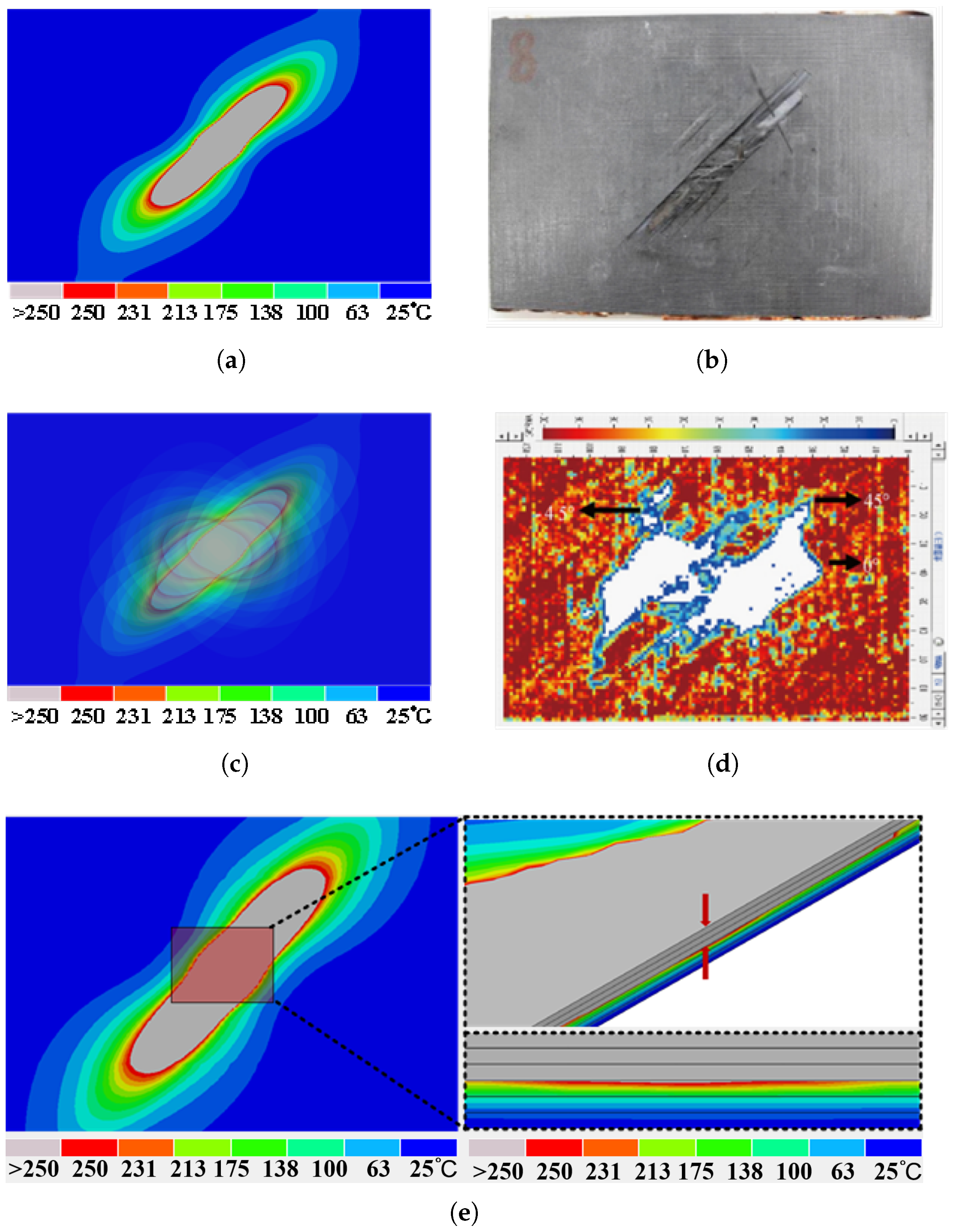
2.3. Model Validation
To validate the accuracy of the model, finite element analysis results of the original CFRP laminate with a layup sequence of [45/0/–45/90]
2S are compared with experimental outcomes from the reference, as depicted in
Figure 4. Fu et al. [
24] conducted direct-effect lightning current experiments, utilizing an 8/20 waveform with a peak current of I = 50 kA to test unprotected CFRP specimens. The specimens were of IM600/133 specification, measuring 150 mm × 100 mm with a single ply thickness of 0.191 mm, consisted of 16 plies, and featured the same layup sequence [45/0/–45/90]
2S.
In the simulation, after the lightning current is fully applied, the final temperature field of the laminate is output. The epoxy resin starts to degrade at temperatures above 250 °C; therefore, the region where the temperature exceeds 250 °C (highlighted in gray in the damage diagram) is considered the damaged area of the CFRP laminate. The shape and size of this damage zone are then compared to experimental results; as depicted in
Figure 4, the area and shape of the damage zone within the finite element model closely resemble the damage region observed in the experimental counterpart. The scale represents the final temperature distribution of the laminate after being subjected to the lightning current. We use this scale to simulate the ablation damage area of the laminate. The scale progresses from right to left, indicating temperatures from low to high, with the upper bound shown in gray, representing the ablation damage area of the laminate. For a CFRP laminate subjected to a peak current of 50 kA, the maximum damaged area in the finite element model is 12.46 cm
2, with a discrepancy of less than 4% compared to the measured value in the literature (12.46∼12 cm
2). The results of the ultrasonic C-scan, reveal the internal damage of the material, which is consistent with the internal damage contour. Furthermore, the number of damaged layers, identified through temperature profiles across the thickness, corresponds to the three layers exhibiting the same peak impact current observed in the C-scan results, confirming the model’s validity.
2.4. Analysis of Lightning Strike Simulation Results
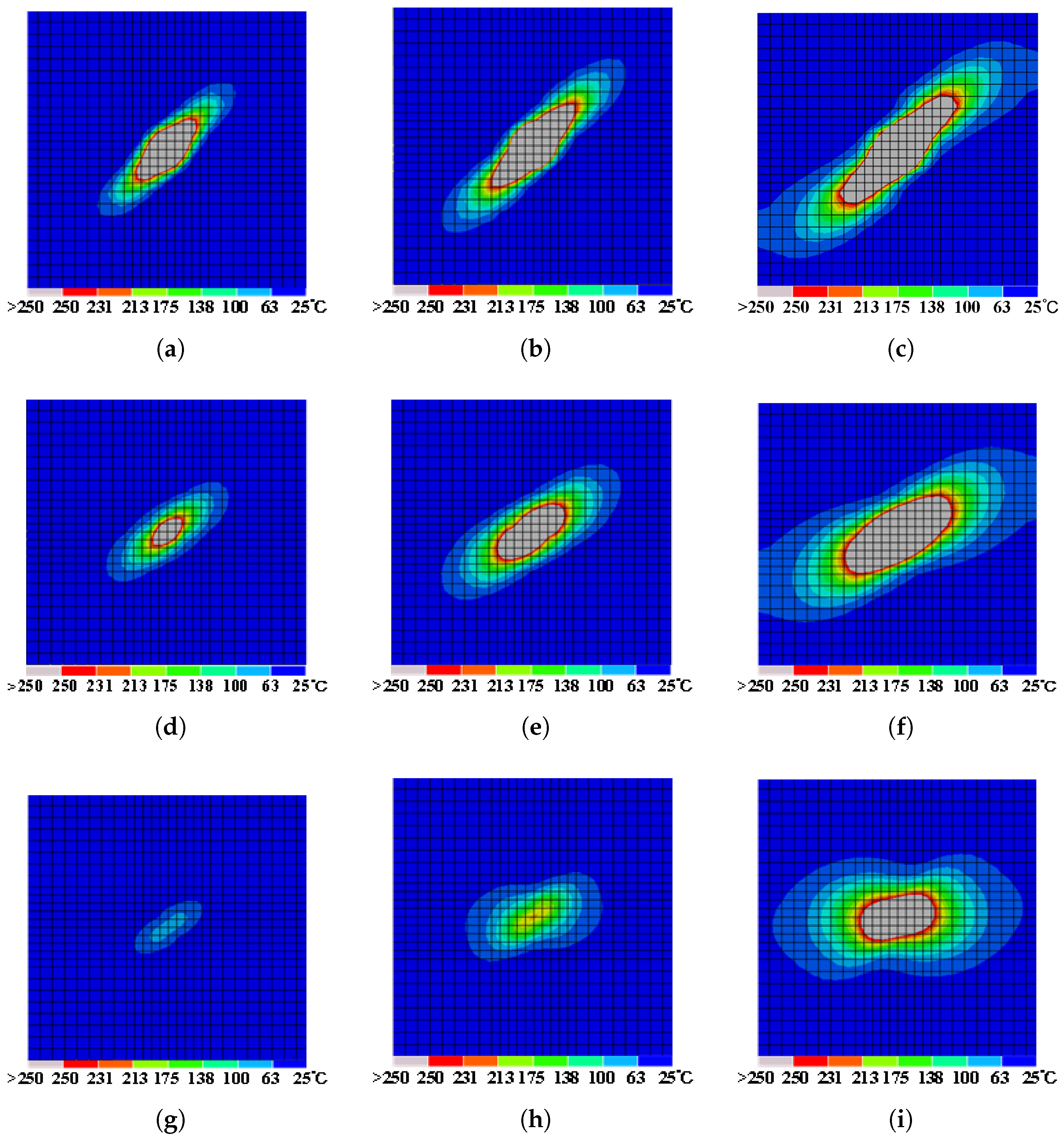
When subjected to a lightning current with an 8/20 µs and a peak value of 20 kA, the temperature variation predominantly affects the initial four plies of the laminates. Among these, the ablation damage is predominantly concentrated in the top three plies, corresponding to areas where temperatures exceed 250 °C, as illustrated in
Figure 5a–c, with no significant ablation damage observed in the fourth ply and those below.
The in-plane damage to the laminate exhibits distinct directional characteristics. The most severe damage is observed in the first ply at the lightning entry point, manifesting as an approximately elliptical shape aligned with the 45° fiber direction, as shown in
Figure 5a. The superior electrical and thermal conductivity along the fiber axis accounts for the preferential propagation of current and heat, resulting in a more extensive temperature rise and consequently more pronounced thermal damage within these regions. The second ply’s damage pattern, which does not align with its 0° fiber orientation, is due to heat conducted from the upper ply, as shown in
Figure 5b. This heat transfer results in damage propagation towards the angle between the two plies. The third ply exhibits damage consistent with the pattern observed in the second ply. To comprehensively analyze the damage phenomena induced by lightning, this study conducted a series of simulated lightning strike simulations with different peak values. The results of the damage are compiled and presented in
Figure 6.
The greater the peak current, the higher the intensity of the transient current through the laminate, resulting in a greater amount of energy transferred by the lightning strike, and consequently, an increased area of ablation damage.
The most severe areas of ablation damage consistently localize near the primary strike point of the first ply, extending predominantly along the 45° fiber orientation. Increased peak currents correspond to enlarged damage areas. The damage pattern in the second ply mirrors that of the first ply, following the same principles of current conduction. At peak currents of 5 kA, 10 kA, and 20 kA, the damage and ablation areas of the laminate measure 4.91 cm2, 10.24 cm2, and 15.35 cm2, respectively.
Furthermore, an increase in peak current is associated with deeper damage, suggesting a direct correlation between electrical current intensity and ablation depth. A comparative analysis with the 20 kA peak current scenario reveals a noticeable reduction in ablation depth at lower peak currents (5–10 kA), primarily confined to regions of the first two plies exhibiting temperatures exceeding 250 °C. No ablation damage regions manifest in the third ply. This observation can be attributed to the dissipation of most of the lightning current’s thermal effects, including resin pyrolysis and carbon fiber sublimation, by the preceding layers.
In all, the damage patterns at varying peak currents remain nearly consistent, with changes in current intensity primarily affecting the extent and depth of damage, rather than altering the propagation pathway of the current.
3. Analysis of Lightning Strike Effects on Patch-Repaired Composite
To mitigate maintenance costs, composite structures with minor lightning-induced damage are typically repaired with patches. Ideally, repairs should restore the structure’s resistance to lightning strikes without exacerbating damage. This study proceeds with an evaluation of the patch-repaired structure’s performance under identical lightning strike currents, employing simulation testing methods.
3.1. Ablation Damage Results of Patch-Repaired Laminate
3.1.1. Patch Repair of Damaged Laminated Composites
In the current study, a simulation model was developed for the patch repair process of damaged regions in laminate composites. This model employs a stratified repair strategy aimed at maximizing structural integrity while minimizing unnecessary repair steps. Specifically, the repair operations in the simulation are conducted sequentially from the innermost composite ply to the outermost ply, applying patches to each ply in turn. Additionally, to address the irregular and misaligned ablation damage across different plies of the laminate, patches of varying sizes and consistent shapes were selected for the repair, in alignment with established practical methods. For ablation damage under 5 kA, minimally circumscribed circular patches were designed for the first and second layers of the damage area.
Figure 7 shows a schematic of the patch assembly on the substrate laminate.
3.1.2. Lightning Strike Damage to Patch-Repaired Laminate
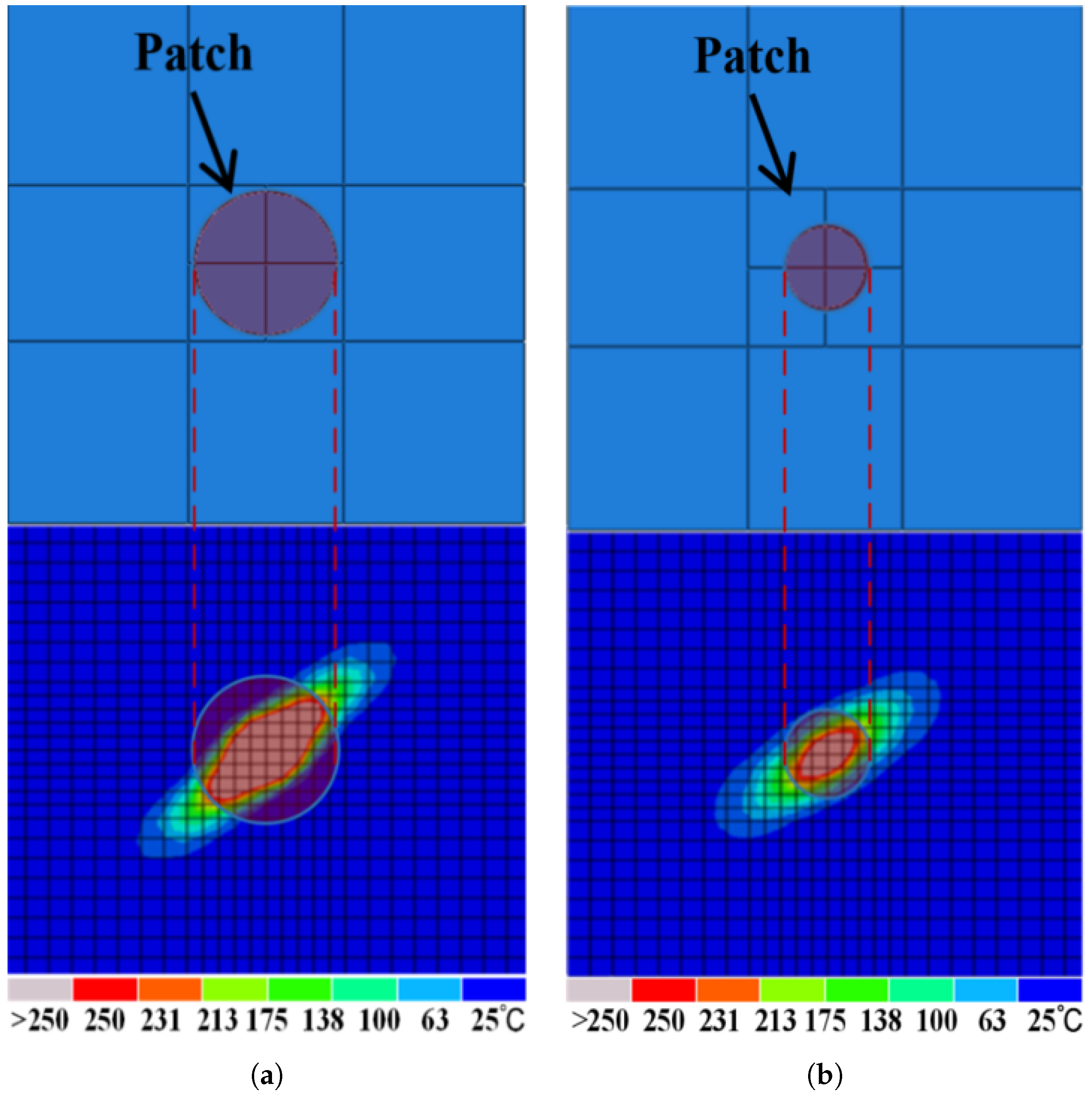
When applying a 5 kA peak current to the repaired laminate,
Figure 8a shows that within the first ply, ablation damage is observed along the 45° fiber direction, which is confined to the boundary of the circular patch. This is attributed to the misalignment of fibers at the joint face between the patch and the original laminate, effectively causing fiber breakage at the junction. The misalignment limits current transfer to the laminate, containing damage within the patched area. Also, a notable temperature rise above 175 °C is observed at the laminate’s surface. This may be ascribed to the presence of minute gaps at the junction (unlike newly manufactured laminates, repaired sections cannot achieve the perfect, seamless fit of the original material, resulting in minute gaps) which diminish the thermal conductivity and increase the thermal resistance. An increase in thermal resistance within the damaged region may lead to a redistribution of heat around the area, thereby influencing the overall temperature field of the whole ply. However, ablation damage extends beyond the patch area to the second ply, with two additional damage regions noted along the 45° fiber direction, as shown in
Figure 8b. Damage within the patch area shows no correlation with other laminate areas, with its cause analyzable from two perspectives: firstly, damage within the patch area is due to the dielectric breakdown of the upper plies, allowing the current to continue penetrating along the thickness direction of the laminate; secondly, damage within the laminate area is caused by intense heat being conveyed to the second ply via thermal conduction. The area of damage measured is 6.55 cm
2, which represents a 33.67% increase from the original structure’s damage area subjected to the same lightning strike current (4.91∼6.55 cm
2). This damage increase is primarily attributed to the new damage areas on the second ply, which are discontinuous from the damage in the patched area and may be challenging to identify during actual repair processes. Consequently, there exists a potential risk in the laminate patch repair, necessitating optimization of current repair methodologies to mitigate adverse effects at the joint face.
3.2. Optimizing Aluminum Coating Applications for Repaired Laminate
Although patching techniques can maintain structural integrity, previous simulation studies have indicated that patch repairs are unable to evenly distribute the current and heat generated by lightning strikes as the original structure does. In order to optimize the patch repair strategy, this study employs a method of applying an aluminum coating on the surface of the repaired structure to address the conductivity interruption caused by the patch repair. The aluminum coating serves a dual purpose: restoring the broken conductive pathways at fiber misalignment areas and providing overall lightning protection by dispersing electric current through a Faraday cage-like effect. The coating is applied to the repaired structure’s surface, and its position is not significantly influenced by the randomness of the lightning strike location, ensuring a more effective dispersion of the lightning current. It is anticipated that this improvement will significantly reduce the current density passing through the structure, thereby more effectively directing and dispersing lightning currents. Additionally, a study on the transient behavior of aluminum-coated structures under lightning conditions has shown that the effects of thermal expansion coefficients are primarily significant in long-term environments. In contrast, during short-term high-current impacts, the effectiveness of the coating is more closely related to its conductivity and thermal stability. As this study focuses on the effects of electro-thermal coupling, primarily analyzing the temperature-dependent properties of the materials under lightning conditions, the thermal expansion coefficient of the aluminum coating is not considered.
3.2.1. Impact of Aluminum Coating on Damage Reduction in Patch-Repaired Laminate
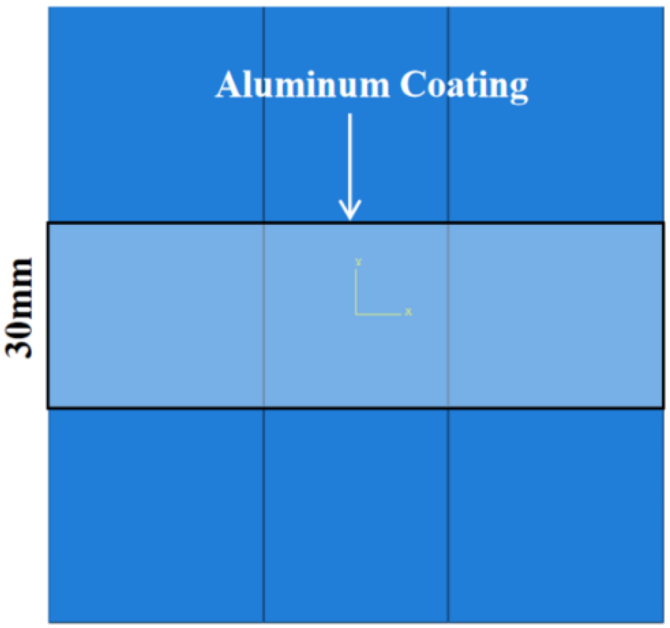
A 0.01 mm thick aluminum coating was locally applied to the geometric center of the structure along the x-axis direction, measuring 100 cm in length and 30 cm in width, as shown in
Figure 9. This targeted application covered the junction, and was anticipated to enhance surface electrical conductivity. Under a 5 kA peak current, no ablation damage was observed on the surface or within the structure. This indicates that the high electrical conductivity of aluminum provides conductive pathways, potentially mitigating breaks in current flow caused by misaligned fibers at the junction, thereby enabling the structure to uniformly disperse the current and heat generated by lightning strikes.
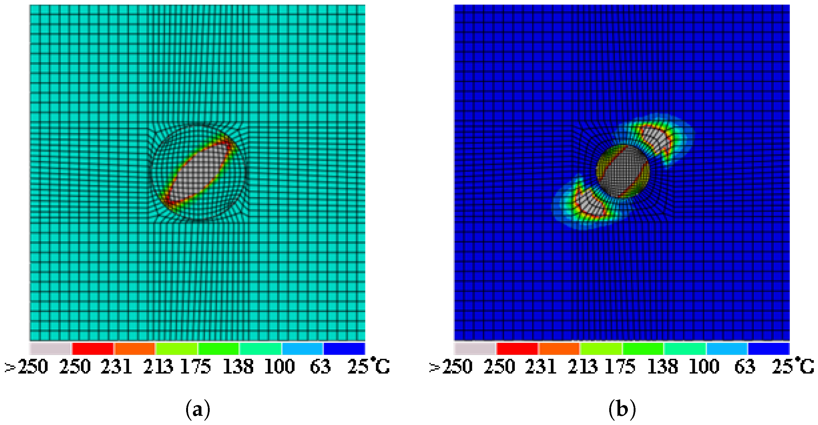
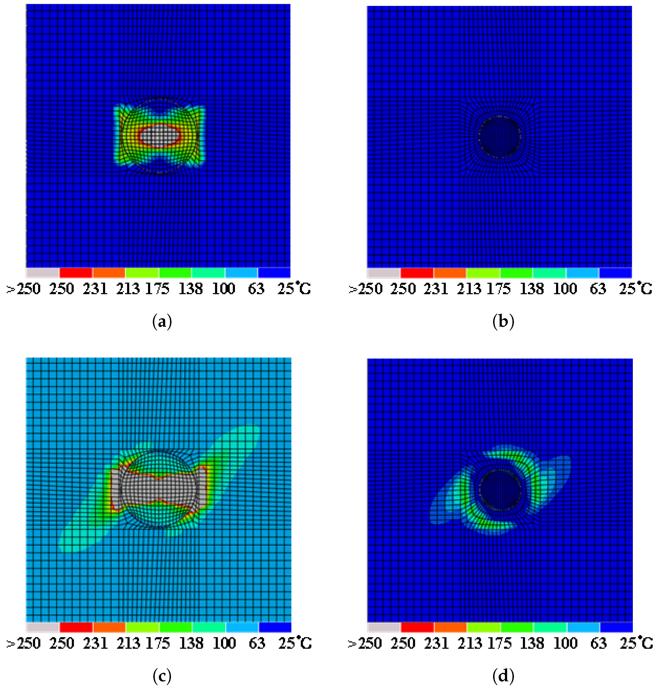
To assess the lightning strike protection of a structure subjected to high-intensity currents, this study amplified the peak current to 20 times and 40 times the initial test value, respectively, applying simulated currents of 100 kA and 200 kA. As depicted in
Figure 10, the surface damage area was significantly reduced. Furthermore, no ablation damage was observed in the second ply, neither in the patch nor the laminate. The electrical conductivity of aluminum alloy is three orders of magnitude higher than that of the laminate, enabling more efficient conduction and thus reducing the current density within the laminate.
Figure 10a shows a symmetrical diamond-shaped damage area formed by the uniform expansion of ablation damage around the lightning strike entry point due to the aluminum coating. This phenomenon can be attributed to the isotropic conductivity of aluminum. However, when the current was increased to 200 kA, as shown in
Figure 10b, the damage initially extended to the junction between the patch and the laminated structure, further propagating towards the main body of the laminate along this direction, forming an approximate rectangular ablation area. This suggests that under high current densities, the aluminum coating may reach its current-carrying capacity limit.
Analysis of the damage results demonstrated that the application of a localized aluminum coating on the surface significantly enhanced the structure’s lightning protection performance, reducing damage areas by 78.6% under 100 kA, where the damage areas were reduced by compared to uncoated controls. However, the protective strategy may introduce substantial weight when applied on a larger scale, potentially adversely affecting structural performance. Therefore, future research endeavors should explore more optimized coating strategies.
3.2.2. Impact of Aluminum Coating Width on the Lightning Protection Ability
Reduction in the aluminum coating’s width to 20 mm and 10 mm, respectively, resulted in incomplete coverage of the patch-repaired area. The damage areas measured
and
under peak currents of 100 kA and 200 kA, respectively. As depicted in
Figure 11, ablation damage was observed only in the first ply. Compared to the damage area at a coating width of 30 mm, the damage areas were reduced by 9.72% (
) and 28.17% (
) with 20 mm and 10 mm widths, respectively.
3.2.3. Impact of Aluminum Coating Shape on the Lightning Protection Ability
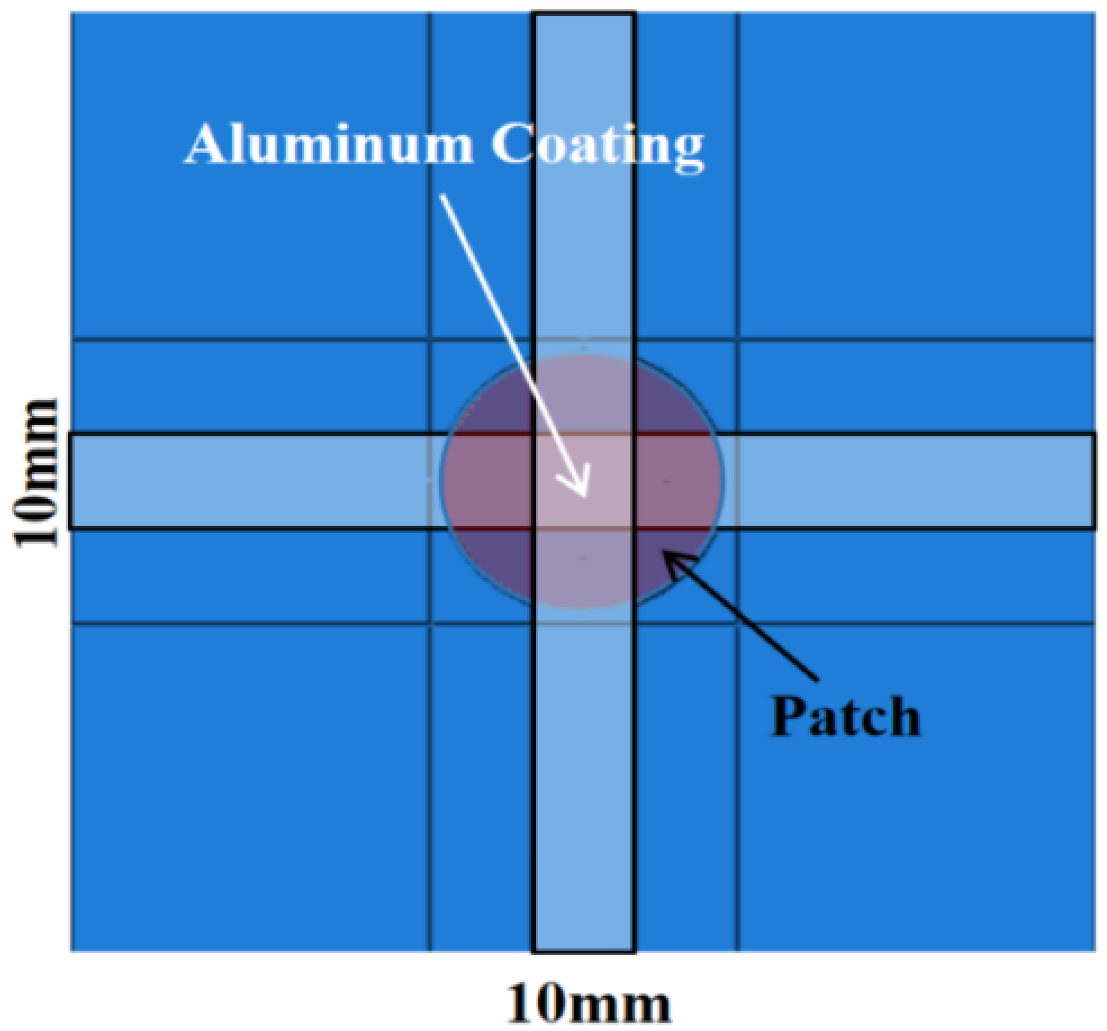
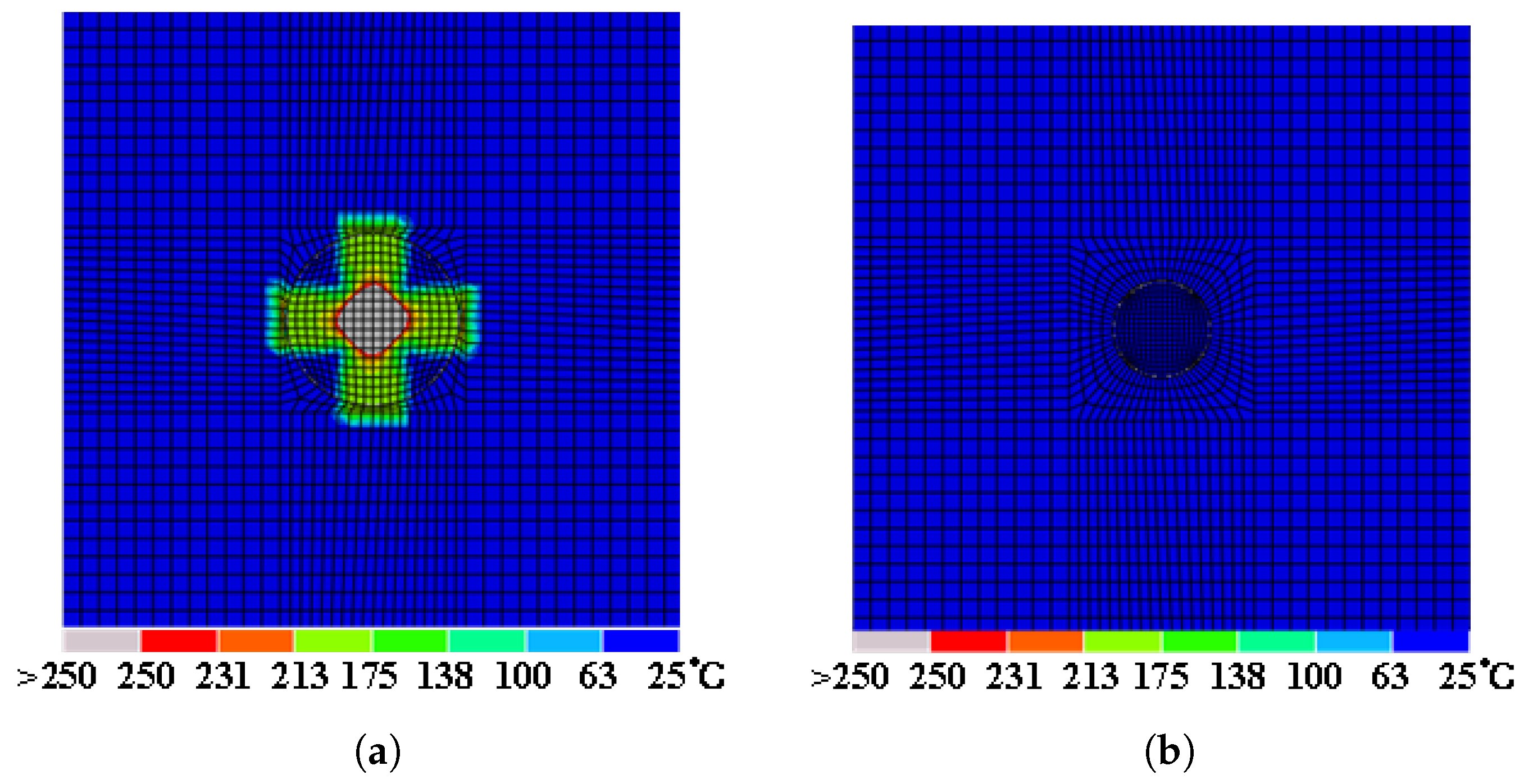
A cross-shaped aluminum coating, 10 mm in width, was applied at the geometric center of the structure’s surface.
Figure 12 presents the assembly of the cross-shaped aluminum coating and the repaired structure. Upon exposure to a 100 kA peak current, the ablation damage, as depicted in
Figure 13, was confined to the first ply, with an area of 1.36 mm
2. This damage area represents reductions of 26.49%, 18.5%, and 74.72% compared to the groups with 30 mm, 20 mm, and 10 mm aluminum coatings, respectively. Furthermore, it is a significant 79.24% reduction compared to the uncoated controls.
The damage area exhibits an equilateral diamond shape, attributed to the additional aluminum coating along the y-axis direction, which provides an alternative conduction pathway for lightning currents. Furthermore, the interconnection between coatings facilitates a more uniform dispersion of lightning currents, concentrating the damage within a relatively smaller area and effectively reducing the affected area. This design aligns with the comprehensive requirements of the modern aviation industry for lightweight and high-performance materials. While the locus of lightning strikes is random, the cross-shaped coating was specifically chosen for its ability to optimize conductivity in critical regions such as leading-edge tips, where lightning damage tends to be more significant. Moreover, the design optimizes conductivity without introducing unnecessary weight, which is crucial for maintaining the aircraft’s balance. This strategy ensures that the repair structure can withstand lightning damage while minimizing the added weight, an important consideration for aircraft performance and safety. For instance, Article 25.581 of the Airworthiness Standards for Transport Category Airplanes (CCAR-25-R4 ), issued by CAAC, demonstrates that localized protection for specific areas is a reasonable and efficient approach.
4. Conclusions
In this study, finite element analysis models were developed to assess lightning-induced damage in both original and patch-repaired composite laminates, based on electro-thermal coupling effects. The model’s accuracy was validated through comparisons with numerical simulations and experimental results. Due to the misalignment of fibers at the junction between the patch and the laminate, the repaired structure experiences more severe lightning-induced damage when subjected to the same lightning current. Therefore, the application of an aluminum coating to the repaired structure is optimal, although potential challenges such as adhesion durability under service conditions and electrochemical corrosion risks between carbon fibers and aluminum should be considered for practical repair solutions. The following conclusions can be drawn:
Patch repairs are unable to evenly distribute the current and heat generated by lightning strikes in contrast to the original structure, leading to current penetration along the thickness direction due to dielectric breakdown in the upper layers. This results in greater internal lightning damage, with the damage area increasing by 33.67% compared to the original structure,
Applying an aluminum coating on the repaired laminate’s surface reduced the current density through the patch and laminate, resulting in a 78.6% decrease in damage area under a 100 kA peak current. However, this protective strategy would lead to a significant weight increase when scaled up for multiple strike locations,
Reducing the width of the aluminum coating minimizes weight. When the width is reduced to 20 mm, the current dispersion efficiency decreases. Further reduction to 10 mm causes the boundary of ablation damage to extend beyond the patch’s edge, significantly increasing the ablation area and markedly diminishing the protective effect of the aluminum coating,
Applying cross-shaped aluminum coatings to the repaired laminate’s surface provides additional conductive paths, facilitating a more uniform dispersion of lightning current and concentrating damage within a relatively smaller area, This results in a significant reduction of 79.24% in the damage area compared to the uncoated controls.
Simulation results based on electro-thermal coupling confirm the effectiveness of the cross-shaped aluminum coating in reducing lightning-induced damage to the patch-repaired structure. This finding also paves the way for the development of more effective repair techniques and lightning protection strategies in composite material applications.
Future work could benefit from incorporating thermo-electro-mechanical coupling, particularly by considering the thermal expansion coefficient of the aluminum coating. Additionally, improving repair durability and minimizing maintenance frequency represent critical research directions for more sustainable solutions. The application of protective layers such as Tedlar films prior to aluminum coating deserves investigation as a potential approach to enhance long-term performance. These advancements would collectively provide a more comprehensive understanding of how thermal, electrical, and mechanical effects interact in repaired composite structures while extending their service life.


