Article

Influence of Baffle Location on the Diodicity of Tesla Valves

1
Key Laboratory of Special Purpose Equipment and Advanced Manufacturing Technology, Ministry of Education & Zhejiang Province, Zhejiang University of Technology, Hangzhou 310024, China
2
Department of Mechanical Engineering, Hangzhou City University, Hangzhou 310015, China
3
State Key Laboratory of Fluid Power and Mechatronic Systems, School of Mechanical Engineering, Zhejiang University, Hangzhou 310058, China
*
Author to whom correspondence should be addressed.
Appl. Sci. 2025, 15(10), 5526; https://doi.org/10.3390/app15105526
Submission received: 19 February 2025 / Revised: 18 April 2025 / Accepted: 6 May 2025 / Published: 15 May 2025

Abstract

:
The Tesla valve (TV) is a valvular conduit that allows fluid to flow in one direction while restricting flow in the opposite direction, making it useful for enhancing fluid control in the field of microfluidics. Our previous research has found that the enhancement of multi-stage TVs’ diodicity is mainly due to the interstage non-uniform flow field. In this study, we introduce baffles in different positions to discover the effect of non-uniform flow field on single-stage TV’s diodicity. We employed 3D printing technology to fabricate a TV for experimental purposes. The experimental data revealed that flow distortion can lead to an increase in diodicity of up to 30% for the studied single-stage TV. Concurrently, we conducted simulations, establishing a simulation model, and then compared the results of the simulation model with the experimental outcomes. This comparison demonstrated the reliability of the model. The detailed analysis indicates that the high-performance optimization is attributed to the baffle design, which preferentially directs fluid into the arc channel, enhancing reverse flow resistance while minimally affecting forward flow resistance. These findings provide valuable strategies for the optimization of the design and performance prediction of single-stage Tesla valves.

1. Introduction

The Tesla valve (TV), invented by the well-known inventor and engineer Nikola Tesla, has a unique design with an asymmetrical structure [1], which not only simplifies the valve’s construction but also enhances its reliability and durability across a myriad of industrial applications [2,3]. TVs are widely used in thermal manipulation fluidics [4,5,6], micromixers [7,8,9], and micropumps [10,11].
Building upon previous research, this study has significantly enhanced the diodicity of single-stage Tesla valves by introducing baffle designs. Through a detailed analysis of the impact of baffle placement on the flow field, specific optimization recommendations have been proposed. Compared with the research by Hyun et al. [12], this study not only focuses on the effects of channel dimensions and fluid properties but also achieves remarkable performance improvements through geometric optimization. In contrast to the work by Yang et al. [13], this study places greater emphasis on enhancing diodicity via geometric optimization rather than relying on complex microfluidic techniques. When compared with the study by Nguyen et al. [14], this research further optimizes the non-uniformity of the flow field by incorporating baffle designs, thereby achieving higher diodicity. These findings offer new insights and methodologies for the advancement of microfluidic technologies. Reference [15] defines the diodicity as follows: the ratio of pressure drop during reverse flow to pressure drop during forward flow. The formula is as follows:
D i = ( Δ P r ) / ( Δ P f )
Studies have shown that the design parameters and structural layout of single-stage TV have a significant impact on its diodicity [16,17]. Research indicates that reducing flow channel angles significantly impacts valve performance. Smaller angles increase resistance to reverse flow, thereby enhancing valve diodicity. Increasing inlet flow velocities is another parameter that can refine diodicity [18,19,20]. Higher velocities lead to a more substantial pressure differential across the valve, subsequently bolstering its diodicity [21,22]. The aspect ratio, defined as the ratio of the width to the height of the flow channel section, plays a crucial role in fluid dynamics. An increased aspect ratio promotes streamlined flow, reducing turbulence and enhancing the valve’s diodicity [23,24,25]. Shortening the lengths of straight flow channels also improves diodicity. By reducing the length, the valve can more effectively resist reverse flow, as there is less distance for fluid to accumulate momentum in the reverse direction [26,27,28,29]. For TVs operating at low Reynolds numbers, optimizing the width of the flow channel section is crucial. An optimally adjusted width facilitates more controlled flow, enhancing valve performance by reducing resistance to forward flow and increasing resistance to reverse flow [30]. Some researchers have employed topological optimization techniques to further refine the diodicity [31]. Although there is a wealth of literature on the structural optimization design of single-stage TVs, most of it remains at the level of adjusting geometric parameters, without delving into optimization based on the inherent characteristics.
Our previous research has shown that increasing the number of stages significantly enhances the performance of multi-stage TVs, primarily due to the inherent characteristics of the TV that lead to non-uniformity in the flow field [32,33]. Therefore, we propose the incorporation of baffles into the TV design. We fabricated the TVs with baffles using 3D printing technology for the experiment, while simultaneously developing a simulation model to analyze their diodicity. Such a modification introduces non-uniformity into the flow field, which subsequently modulates the valve’s diodicity. The proposed structure is designed to replicate the non-uniformity observed in multi-stage valves, thereby potentially optimizing diodicity without incurring the complexity associated with additional stages.

2. Problem Setup

2.1. Geometric Model and Design Proposal

Figure 1 illustrates the geometric dimensions of the TV utilized in this study. Optimization cases incorporating baffles are depicted in Figure 2 and Figure 3. Baffles are strategically placed on the upper and lower walls of the inlet and outlet channels, respectively, and are indicated by dashed-line circles in the figures. The design parameters encompass baffle thickness, baffle height, and the distance from the baffle to the channel bifurcation. The baffle parameters specified in this study are as follows: the baffle width is w = 0.1 mm, the baffle height is h = 1 mm, and the distance from the baffle to the channel bifurcation is d = 1.25 mm.

2.2. Simulation Methods

Figure 4 presents the meshing details of the single-stage TV, delineating the comprehensive meshing of its fluid domain. In this investigation, water at a temperature of approximately 20 °C serves as the working fluid. Referring to the standard thermophysical properties, the density of water is recorded as 998.2 kg/m3, and its dynamic viscosity is 0.001 Pa·s. An inlet boundary condition specifying velocity is imposed at the inlet, while an outlet boundary condition specifying pressure is applied at the outlet. The outlet gauge pressure is prescribed as 0 Pa, reflecting this study’s focus on the flow characteristics of the TV under normal operating conditions, excluding cavitation effects. The locations of the inlet and outlet are ascertained in accordance with the flow direction as depicted in Figure 1. The remaining boundaries of the model are designated as smooth, no-slip wall boundaries.
The continuity and incompressible Navier–Stokes equations are used in the following form:
ρ u · u = p + μ 2 u
· u = 0
where ρ , u , p , a n d   μ denote the density, velocity, pressure, and dynamic viscosity of the fluid. The simulations detailed in this paper were performed utilizing the pressure-based steady solver within Ansys Fluent. Given that the Reynolds number is within the range from 1 to 300, a laminar flow model was employed for this analysis. The steady-state flow field solution was achieved using the SIMPLE (Semi-Implicit Method for Pressure-Linked Equations) algorithm for pressure-velocity coupling. Both convective and diffusive terms were discretized employing a second-order upwind scheme. The convergence criteria were established to ensure computational convergence when the residuals for the continuity equation and the momentum conservation equation fell below 1 × 10⁻⁶.
Grid partitioning is a critical component of numerical flow field simulations. Ensuring an adequate number and high-quality grid is essential for obtaining reliable numerical computation results, achieving good convergence, and maintaining high computational efficiency. While sparse grids may compromise numerical accuracy, overly dense grids can lead to prolonged computational times and excessive resource utilization. As illustrated in Figure 5, by balancing computational accuracy with laboratory server capabilities, this study opted for a grid count of 500,000 for the single-stage TV. The linear relationship between the Di and the Reynolds number, as illustrated in Figure 6, is consistent with the findings reported by Thompson et al. and Truong and Nguyen. The grid quality of the fluid domain for the single-stage TV exceeds 0.8, signifying that the grid resolution is adequate to ensure the simulation’s accuracy.

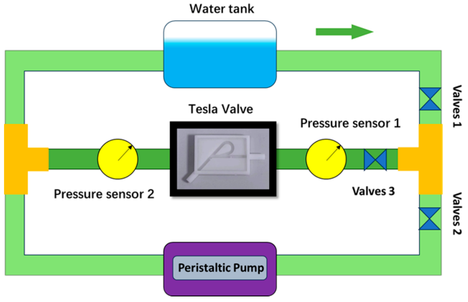
2.3. Experiment Methods

The experimental setup, as shown in Figure 7 and Figure 8, consists of the following main components: a water tank, control valves, a pressure transducer (YK-100B, Xi’an Shelok Instrument Technology Co., Ltd., Xi’an, China, with a range of 0–10 kPa and an accuracy of 0.05%), a Tesla Valve (TV), a peristaltic pump (BT300J-1A, Yuhui Fluid Equipment Co., Ltd., Yangzhou, China), and a graduated cylinder. The Tesla Valve is manufactured using advanced 3D printing technology, precisely meeting the parameter requirements specified in this study. This 3D printing technique enables the precise fabrication of complex geometries that align with the Tesla valve’s flow characteristics, ensuring optimal Di performance. Notably, 3D printing not only accelerates prototyping but also offers cost-effective and flexible manufacturing solutions [34,35]. Additionally, its compatibility with diverse materials expands the potential for functional optimization [35]. This approach guarantees the reliability and repeatability of the experiment. The water tank, measuring 30 cm × 30 cm × 50 cm, serves as an effective pressure source due to its large volume and stable structure, providing a continuous and stable water flow for the experiment. Control valves play a crucial role in the experiment; by accurately adjusting the opening and closing states of the valves, the direction of water flow can be flexibly guided, achieving precise control over the experimental process. Before starting the experiment, it is necessary to operate the valves to expel the air from the Tesla Valve to eliminate the interference of bubbles on the experimental results: open valves 2 and 3 to allow the air to be smoothly discharged, while closing valve 1 to prevent water from entering the Tesla Valve prematurely. During the experiment, water is stably delivered from the tank to the Tesla Valve by opening valves 1 and 3 and closing valve 2, ensuring that the experiment proceeds smoothly under predetermined conditions. After the experiment, water is recirculated back into the tank by opening valves 1 and 2 and closing valve 3, maintaining a stable water level.
The flow rate is controlled by adjusting the water level in the tank, and the flow velocity is calculated by measuring the change in water volume in a specified period using the graduated cylinder. The height of the water level in the tank affects the fluid velocity. When the water level rises, the fluid velocity increases accordingly; conversely, when the water level drops, the velocity decreases. By controlling the water level in the tank, the inflow and outflow rates of the tank can be adjusted. The key to this process lies in utilizing a graduated cylinder, a fundamental measuring tool, to observe and record the subtle changes in water volume over a set time interval. This allows the adjustment of water level to be translated into specific flow rate values, laying a solid foundation for the accuracy of subsequent experimental data. In this experiment, the Reynolds number spans from 100 to 300, calculated using Equation (4). It ingeniously integrates physical quantities such as fluid velocity, density, and viscosity, providing a critical basis for determining the state of fluid flow. At a Reynolds number of 300, the flow rate through the Tesla valve is precisely determined to be 36 milliliters per minute, a result obtained through rigorous control of water level adjustment and flow rate measurement.
The inlet Reynolds number can be defined as follows:
R e = ρ v d / μ
where ρ , v ,   a n d   μ are the density, velocity, and dynamic viscosity of the fluid, respectively. While d denotes a characteristic length, which, in this case, is the hydraulic diameter.
To maximize the reliability of the experimental results, the experiment was conducted five times. During each trial, researchers attentively monitored the readings from the pressure sensors, patiently waiting for the values to stabilize. These stable pressure readings provided accurate raw data for subsequent calculations. The diodicity value was derived by precisely measuring the pressure drop during reverse and forward flows and then calculating the ratio between them using mathematical formulas. Throughout the entire experimental process, all operations were carried out at room temperature. The impact of temperature on liquid properties can be neglected at room temperature, as key properties such as liquid density and viscosity change minimally within this temperature range. This experimental arrangement not only simplifies the conditions but also effectively reduces errors caused by temperature fluctuations, enabling the experimental setup and procedures to more accurately assess the performance of the Tesla valve. This provides strong support for studying its operational characteristics under different flow conditions.

3. Results and Discussion

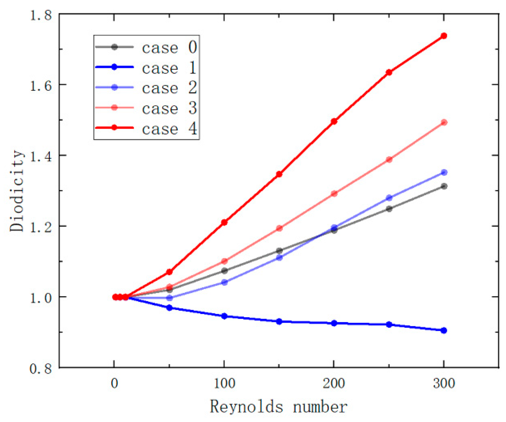
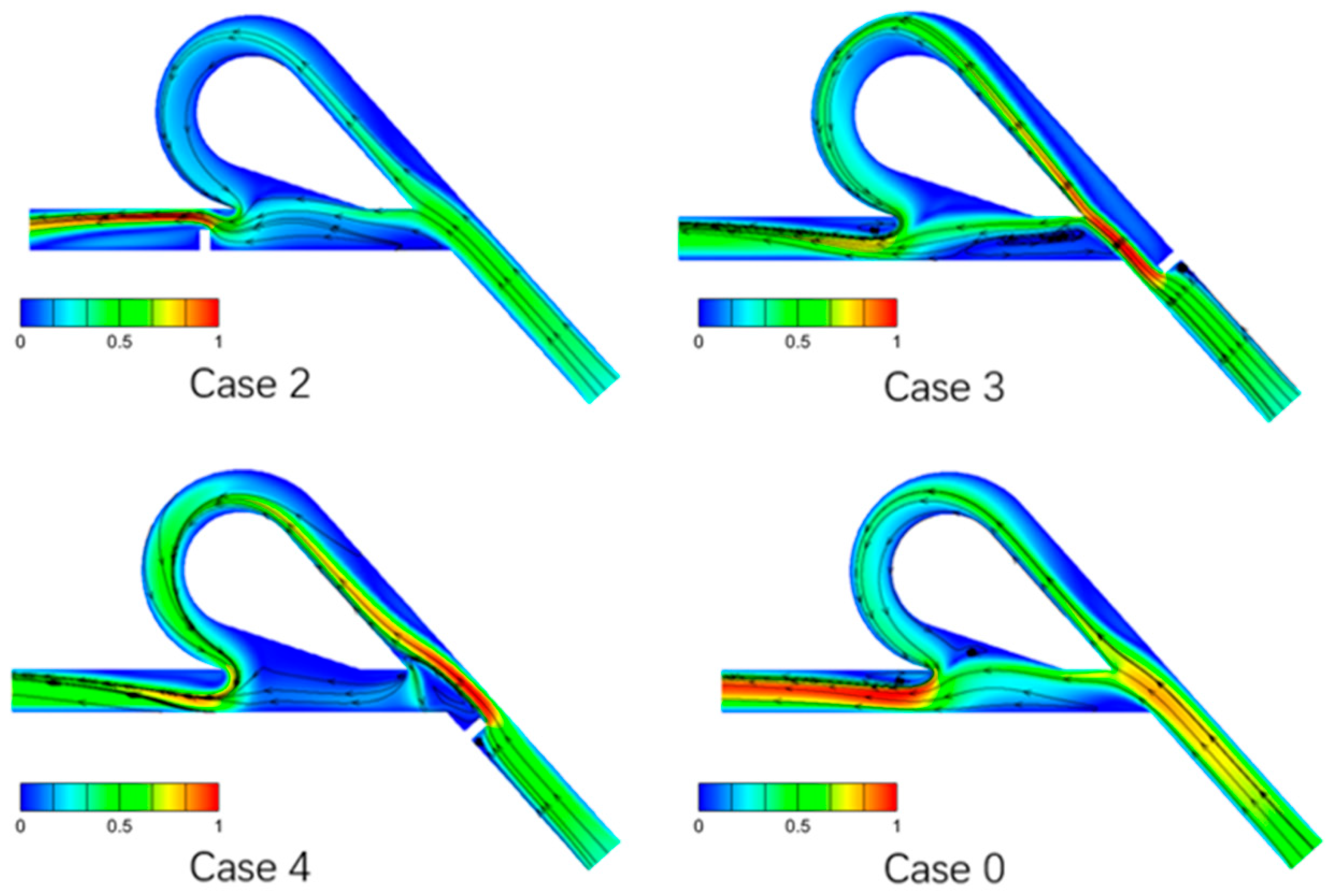
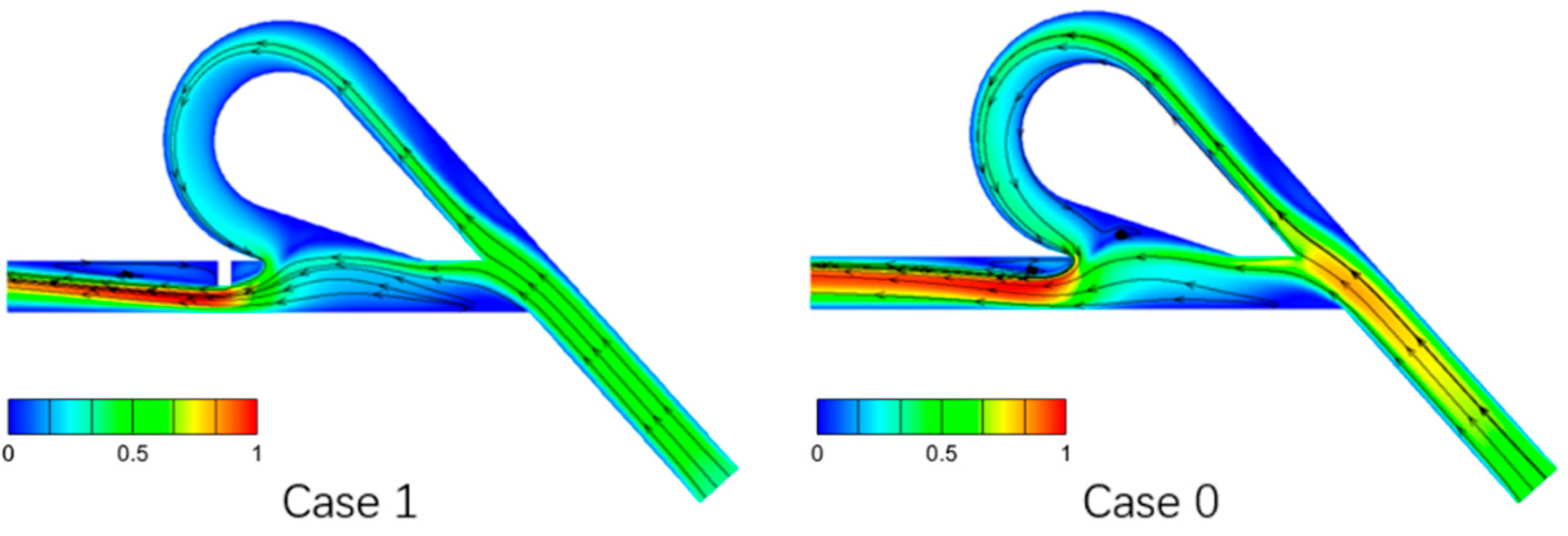
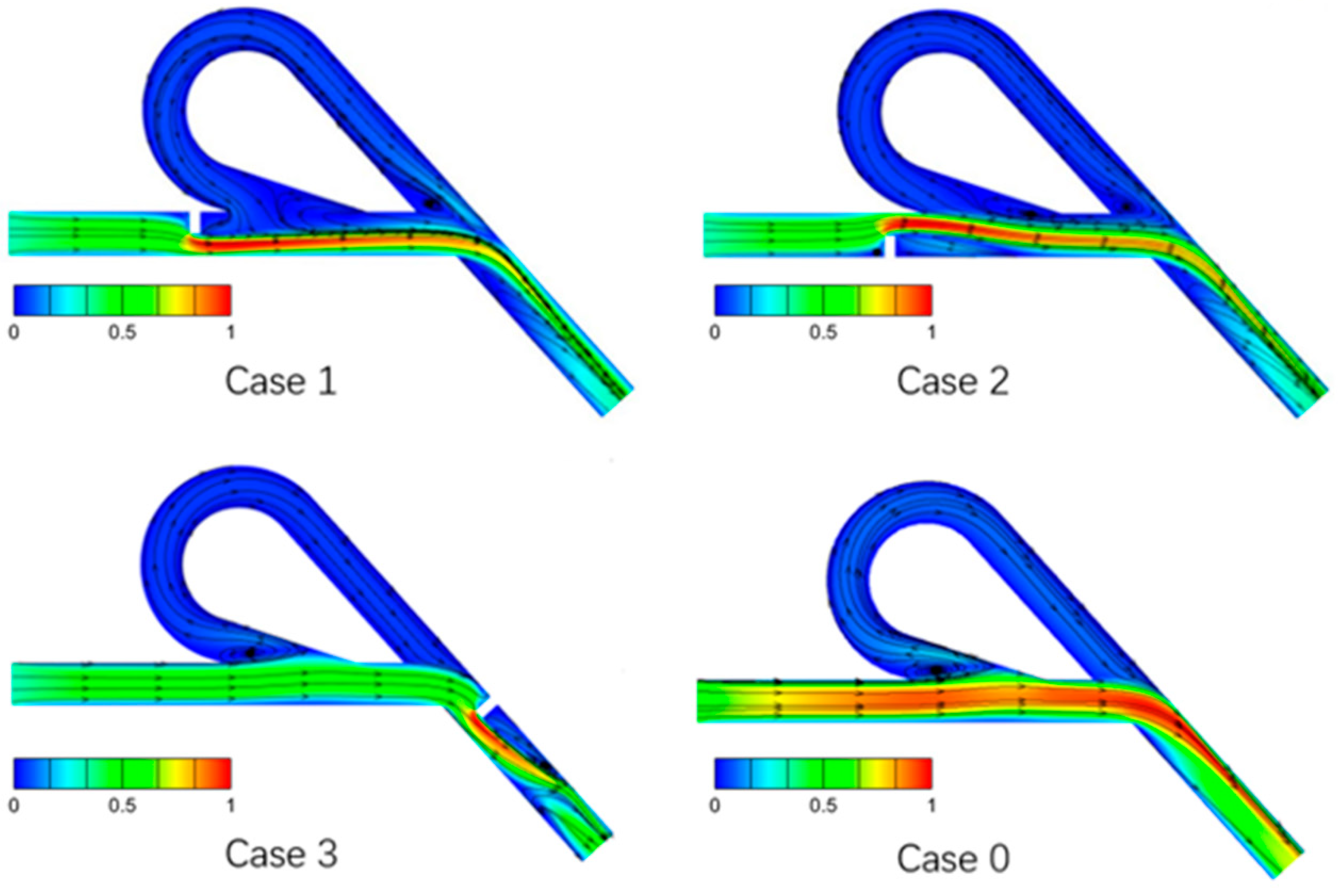
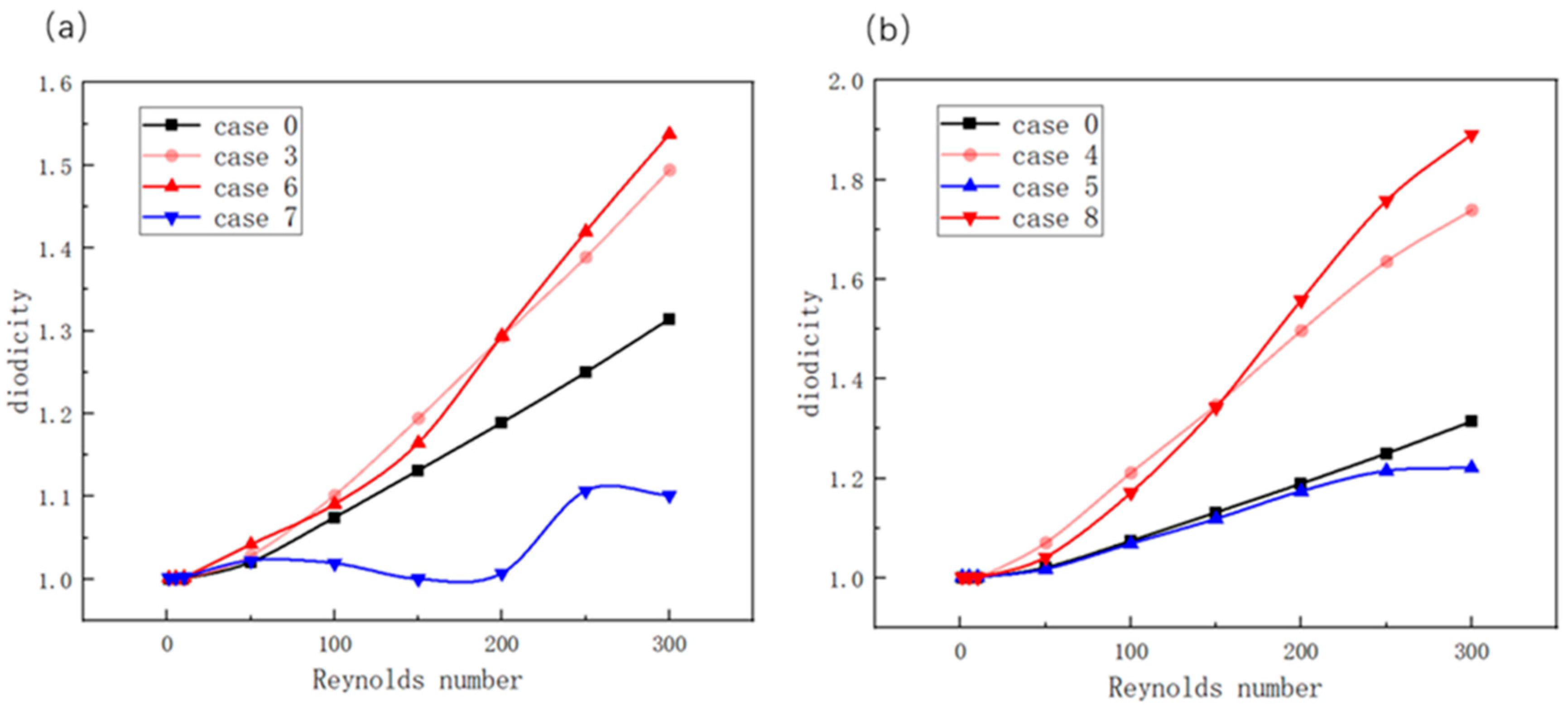
3.1. Influence of Flow Field Non-Uniformity at One Location on the Diodicity

Firstly, we compare the impact of four distinct baffle placement methods on the diodicity of TVs, as illustrated in Figure 2. Figure 9 indicates that, in Case 1, the introduction of baffles diminishes the diodicity. For Case 2, when the inlet Reynolds number is below 200, the diodicity is poorer than that without baffles. Conversely, when the inlet Reynolds number exceeds 200, the inclusion of baffles marginally enhances the diodicity, yet the improvement is not markedly significant. Thus, neither Case 1 nor Case 2 effectively optimizes the diodicity. In contrast, Cases 3 and 4, which feature baffles positioned at the reverse inlet, can substantially improve the performance of the TV. Notably, Case 4 significantly optimizes the diodicity, with the diodicity value increasing by approximately 30% relative to the TV without baffles.
To attain a higher D i , the objective is to maximize reverse pressure drop( Δ P r ) and minimize forward pressure drop ( Δ P f ). The incorporation of baffles in this study inevitably introduces additional resistance to fluid flow, thereby augmenting the overall pressure drop Δ P . Hence, optimizing the D i in the TV design should focus on increasing Δ P r to Δ P f . Consequently, the analysis of the TV’s diodicity should begin with the pressure drops during forward flow ( Δ P f ) and reverse flow ( Δ P r ).
As depicted in Figure 10a,b, the four cases with integrated baffles demonstrate varying levels of enhancement in pressure drop relative to the TV without baffles. A significant discrepancy in pressure drop is observed between Case 1 and Cases 2, 3, and 4 during reverse flow. Nevertheless, Case 4 stands out with a pronounced difference in pressure drop when compared to Cases 1, 2, and 3 during forward flow. Consequently, these cases should be categorized and examined in a grouped manner to delve deeper into this phenomenon from a fluid dynamics standpoint.
In a TV, the fluid’s velocity field is not randomly distributed; rather, it is stabilized by the valve’s internal geometric structure and the fluid’s physical properties, which include velocity, viscosity, and density. The velocity fields for both forward and reverse flows within the TV are illustrated in Figure 11, Figure 12, Figure 13 and Figure 14. An analysis of the forward and reverse flow fields discussed previously enables us to deduce that the incorporation of baffles within the TV can alter the pressure drop across it, thereby affecting its diodicity. Baffles positioned in regions of high velocity can lead to a significant increase in pressure drop, whereas those in low-velocity areas result in a more moderate increase. Upon comparing the flow field results from Case 1 to Case 4, it becomes apparent that, during forward inflow, the fluid predominantly traverses the straight channel branch located below the arc channel branch, resulting in essentially uniform drag along the path. However, the presence of baffles reduces the channel’s cross-sectional area, leading to a non-uniform flow field in the vicinity of the baffles and an increase in local resistance. Consequently, the forward inflow pressure drop increases following the addition of baffles.
It is noteworthy that the non-uniform flow fields generated by baffles at various positions display distinct variations. As shown in Figure 11 and Figure 12, in Case 4, the baffle is situated in a region of reduced flow velocity, which can be analogous to a vortex that diminishes the impedance to fluid flow. Consequently, the resultant increase in pressure drop is comparatively minor.
During the reverse flow process, the fluid navigates through both the arc channel branch and the straight channel branch. In Cases 1 and 2, the presence of the baffle does not alter the direction of fluid flow, resulting in a relatively uniform flow distribution. This leads to a portion of the fluid entering the arc branch and another portion entering the straight branch. However, in Cases 3 and 4, the direction of flow is modified, inducing vortices near the baffle’s location and resulting in a non-uniform flow field. Specifically, in Case 3, the fluid divides with only a minor portion entering the straight channel branch. In contrast, in Case 4, nearly all of the fluid is directed through the arc branch, which significantly increases the reverse flow resistance and consequently results in a substantial increase in pressure drop.
In conclusion, the presence of baffles at the outlet can significantly enhance the diodicity of the TV. Notably, situating the baffles below the outlet of the TV can result in a marked improvement.

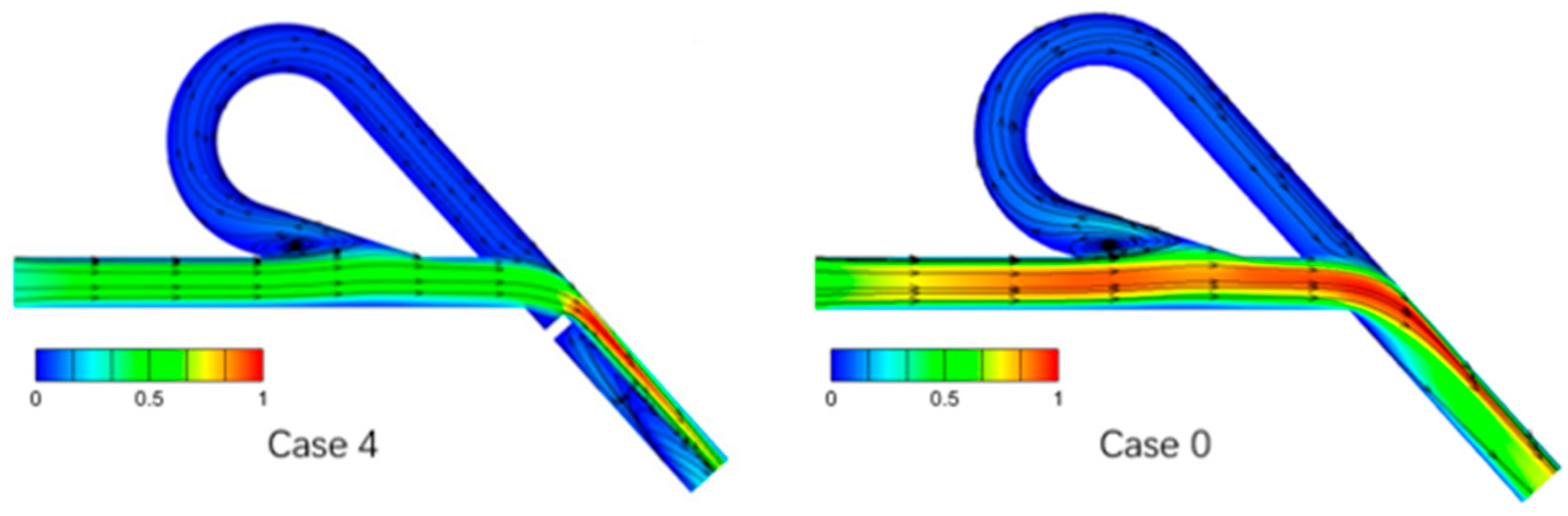
3.2. Influence of Flow Field Non-Uniformity at Two Locations on the Diodicity

Based on the aforementioned findings, we can further refine the design of the TV to more precisely simulate the impact of flow field non-uniformity on its diodicity. Among the four optimization cases previously discussed, it was observed that the non-uniform flow field induced by baffles positioned at the outlet can significantly enhance the diodicity of the TV. Leveraging this insight, Cases 5 to 8 have been proposed, as illustrated in Figure 3. These cases involve pairs of baffles positioned at four distinct locations. The aim of these new cases is to explore the influence of the non-uniform flow field generated by baffles placed at the inlet on the diodicity of the TV.
The pressure drops for the forward and reverse flows in Cases 5 to 8 are presented in Figure 15a,b. The pressure drop exhibits a variation that approximates a quadratic curve in relation to the Reynolds number. In forward flow, the pressure drop curves for Cases 5 and 8, as well as for Cases 6 and 7, are essentially congruent. This congruence implies that the non-uniform flow field induced by the baffles, when relocated to the inlet of the TV, exerts a negligible influence on the pressure difference observed during forward flow.
In reverse flow, a significant difference is observed between the pressure drop curves of Case 5 and Case 8. The curves for Case 6 and Case 7, while exhibiting a smaller difference, also deviate noticeably from the congruence observed in the preceding forward flow phase. This indicates that the repositioning of baffles at the inlet of the TV has a considerable impact on the pressure drop during reverse flow. This impact can be either beneficial or detrimental.
As depicted in Figure 16b, the diodicity of Case 5 is even poorer than that of the case without added baffles, while the diodicity of Case 8, which incorporates two baffles, is further optimized compared to Case 4, which features only one baffle. Figure 15a also demonstrates that baffles positioned downstream of the inlet enhance diodicity, whereas those positioned upstream of it reduce it.
During forward flow, the fluid predominantly traverses the straight channel branch situated below the arc channel branch, culminating in a heightened pressure drop relative to the case without baffles. However, among cases with an equivalent number of baffles, there is scant variation in the frictional resistance encountered by the fluid, and no substantial alteration in the pressure drop is observed across different cases.
In the reverse flow process, in contrast to the preceding optimization case, a vortex is formed above the inlet. In Cases 5 and 7, the baffle positioned above the inlet supplants the vortex effect, exerting a negligible influence on the original flow field and permitting the fluid to pass through with minimal resistance. Nevertheless, the baffles positioned below the inlet in Cases 6 and 8 markedly impede the flow, culminating in an escalated pressure drop.
From the analysis presented, it is clear that the optimization of diodicity is primarily contingent upon the strategic positioning of baffles at the outlet. The installation of baffles at the outlet is a critical factor, and the subsequent addition of baffles at the inlet can further modulate the diodicity. Upon comparing the initial four cases, each with a single baffle, to the subsequent four cases with multiple baffles, it is noted that cases with two baffles exhibit diverse impacts on diodicity optimization. Generally, positioning a baffle below the inlet tends to achieve more favorable optimization results. In contrast, positioning a baffle above the inlet may adversely affect the valve’s performance.
During the optimization of the Tesla Valve’s (TV’s) structure, it is observed that forward flow predominantly traverses the straight channel branch with minimal hindrance. Consequently, the primary focus of optimization efforts should be on the characteristics of reverse flow. To augment the TV’s performance, the optimization strategy should be directed towards guiding the fluid into the arc channel, thereby increasing the resistance to reverse flow. Concurrently, it is imperative to avoid introducing obstacles in regions susceptible to vortex formation, such as above the outlet of the reverse flow. By employing such targeted structural optimization, the diodicity of the TV can be significantly enhanced, thereby facilitating more efficient fluid control.

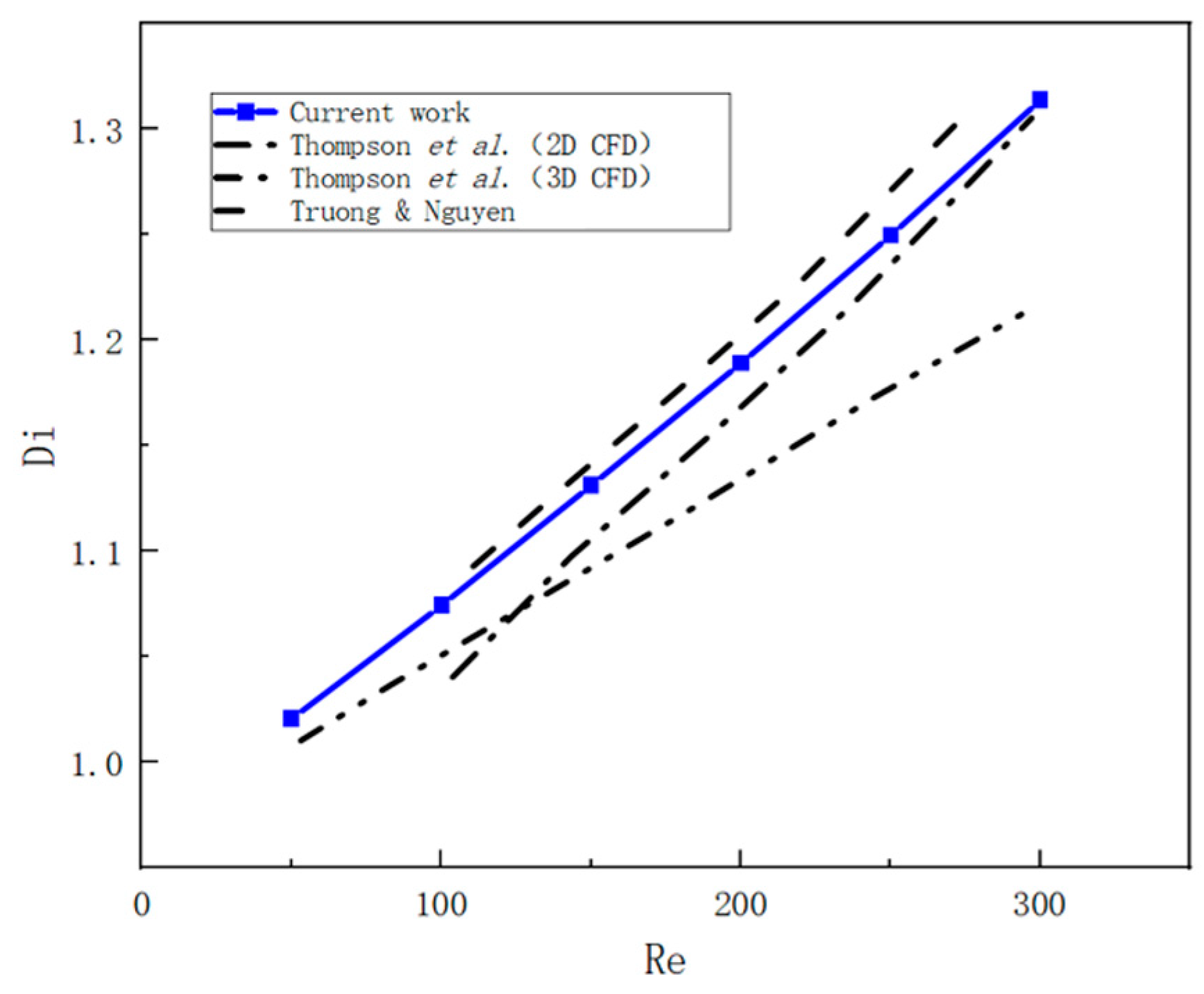
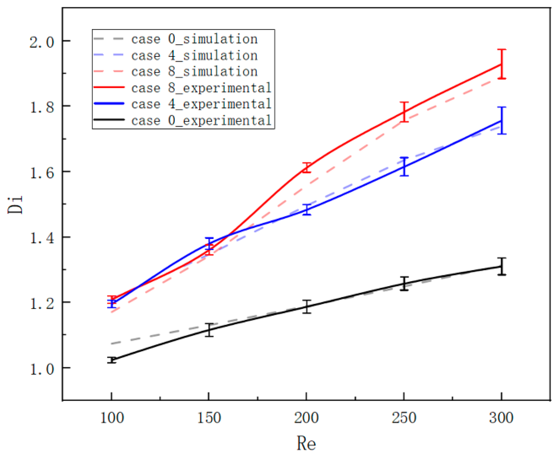
3.3. Comparison of Experimental and Simulation Results

This study conducts a comparative analysis of the TV’s diodicity before and after structural optimization, thereby validating the feasibility of the optimization methodology through experimental analysis. Figure 17 presents a comparison of the diodicity in its original and optimized configurations. Observations from the figure indicate that the incorporation of baffles into the TV, as proposed in this study, significantly enhances its diodicity. Consistent with the experimental data, simulation results demonstrate an increasing trend in diodicity values in conjunction with an increasing flow rate. Throughout the operational range examined, the simulation error is maintained at less than 10%.
During the experiment, the main discrepancy between the experimental and simulation results was found to be due to the non-ideal smoothness of the TV’s flow channel surface and the minute air bubbles adhering to the valve surface. To mitigate these uncertainties, we utilized a peristaltic pump to significantly reduce the presence of bubbles in the fluid and employed 3D printing technology to manufacture the valve model with an improved surface finish. Upon comparing the revised experimental results with the simulation results, the discrepancies observed were minimal, thereby confirming the reliability of the numerical computation results presented in this study.

4. Conclusions

This research provides an in-depth analysis of the impact of baffles within the flow field. By examining the positional effects of baffles, the following conclusions have been derived:
(1)
This research has established that modifications to the flow field substantially affect the diodicity of the TV. The position of baffles at the outlet is instrumental in enhancing optimization, with the most significant improvements being observed when baffles are positioned below the outlet.
(2)
When augmenting the number of baffles, it is imperative to meticulously consider their layout and interactions to minimize flow losses and mitigate adverse effects on flow field structures. A setup with two baffles that generates a non-uniform flow field exerts both beneficial and deleterious effects on the optimization of the diodicity of Tesla Valves (TVs). Positioning baffles below the inlet can enhance diodicity to a certain degree, whereas positioning them above the inlet is counterproductive to the optimization process.
(3)
In TVs, the forward flow predominantly traverses the straight channel branches, leading to minimal variation in the drag experienced by the fluid. Consequently, a structure that directs fluid preferentially into arc channels to enhance reverse flow resistance and prevents obstructions in areas prone to vortex formation, such as above the inlet, achieves superior optimization outcomes.
(4)
Baffles positioned both below the inlet and the outlet yield the optimal enhancement in diodicity, with an optimization magnitude exceeding 40%. These outcomes are predicated on the specific baffle parameters delineated in the preceding text. When a single baffle is positioned, one situated below the outlet achieves a notable increase in diodicity, surpassing 30%.
Overall, this study, employing computational fluid dynamics (CFD) simulations coupled with experimental validation, has demonstrated the potential to enhance the diodicity of TVs by modulating flow field uniformity. The findings offer valuable insights for future design optimizations of TVs, potentially augmenting their efficacy in fluid control applications.

Author Contributions

Conceptualization, P.W.; Methodology, L.L.; Writing—original draft, S.Z.; Writing—review & editing, S.Z.; Supervision, C.D. All authors have read and agreed to the published version of the manuscript.

Funding

This research was funded by the National Natural Science Foundation of China, with grant number 52205072.

Institutional Review Board Statement

Not applicable.

Informed Consent Statement

Not applicable.

Data Availability Statement

Data is contained within the article.

Conflicts of Interest

The authors declare no conflict of interest.

References

  1. Tesla, N. Valvular Conduit. U.S. Patent 1329559A, 3 February 1920. [Google Scholar]
  2. Wang, C.-T.; Chen, Y.-M.; Hong, P.-A.; Wang, Y.-T. Tesla valves in micromixers. Int. J. Chem. React. Eng. 2014, 12, 397–403. [Google Scholar] [CrossRef]
  3. Qian, J.-Y.; Hou, C.-W.; Li, X.-J.; Jin, Z.-J. Actuation mechanism of microvalves: A review. Micromachines 2020, 11, 172. [Google Scholar] [CrossRef] [PubMed]
  4. Lin, S.; Zhao, L.; Guest, J.K.; Weihs, T.P.; Liu, Z. Topology optimization of fixed-geometry fluid diodes. J. Mech. Des. 2015, 137, 081402. [Google Scholar] [CrossRef]
  5. Tesař, V. Time-Delay Circuits for Fluidic Oscillators and Pulse Shapers. Energies 2019, 12, 3071. [Google Scholar] [CrossRef]
  6. Bohm, S.; Phi, H.B.; Moriyama, A.; Runge, E.; Strehle, S.; König, J.; Cierpka, C.; Dittrich, L. Highly efficient passive Tesla valves for microfluidic applications. Microsyst. Nanoeng. 2022, 8, 97. [Google Scholar] [CrossRef]
  7. Buglie, W.L.N.; Tamrin, K.F.; Sheikh, N.A.; Yasin, M.F.M.; Mohamaddan, S. Enhanced fluid mixing using a reversed multistage Tesla micromixer. Chem. Eng. Technol. 2022, 45, 1255–1263. [Google Scholar] [CrossRef]
  8. Wang, J.; Cui, B.; Liu, H.; Chen, X.; Li, Y.; Wang, R.; Lang, T.; Yang, H.; Li, L.; Pan, H.; et al. Tesla valve-based flexible microhybrid chip with unidirectional flow properties. ACS Omega 2022, 7, 31744–31755. [Google Scholar] [CrossRef]
  9. Wang, H.; Chen, X. Optimization of tesla valve-typed micromixer based on simulated annealing algorithm. Surf. Rev. Lett. 2022, 29, 2250094. [Google Scholar] [CrossRef]
  10. Derakhshan, S.; Beigzadeh, B.; Rashidi, M.; Pourrahmani, H. Performance improvement and two-phase flow study of a piezoelectric micropump with tesla nozzle-diffuser microvalves. J. Appl. Fluid Mech. 2019, 12, 341–350. [Google Scholar] [CrossRef]
  11. Yao, Y.; Zhou, Z.; Liu, H.; Li, T.; Gao, X. Valveless piezoelectric pump with reverse diversion channel. Electronics 2021, 10, 1712. [Google Scholar] [CrossRef]
  12. Hyun, W.J.; Kumar, S.; Francis, L.F.; Frisbie, C.D. Open-channel microfluidic diodes based on two-tier junctions. Appl. Phys. Lett. 2018, 113, 193701. [Google Scholar] [CrossRef]
  13. Yang, C.; Li, W.; Zhao, Y.; Shang, L. Flexible liquid-diode microtubes from multimodal microfluidics. Proc. Natl. Acad. Sci. USA 2024, 121, e2402331121. [Google Scholar] [CrossRef]
  14. Nguyen, Q.M.; Abouezzi, J.; Ristroph, L. Early turbulence and pulsatile flows enhance diodicity of Tesla’s macrofluidic valve. Nat. Commun. 2021, 12, 2884. [Google Scholar] [CrossRef]
  15. Tadyszak, K.; Jäger, A.; Pánek, J.; Hrubý, M. Design and Optimization of Microfluidic Vortex Diode. Math. Comput. Appl. 2024, 29, 97. [Google Scholar] [CrossRef]
  16. Lin, Z.; Yin, D.; Tao, J.; Li, Y.; Sun, J.; Zhu, Z. Effect of Shaft Diameter on the Hydrodynamic Torque of Butterfly Valve Disk. J. Fluids Eng. Trans. ASME 2020, 142, 111202. [Google Scholar] [CrossRef] [PubMed]
  17. Lam, R.H.W.; Li, W.J. A Digitally Controllable Polymer-Based Microfluidic Mixing Module Array. Micromachines 2012, 3, 279–294. [Google Scholar] [CrossRef]
  18. Turowski, M.; Chen, Z.; Przekwas, A. Automated generation of compact models for fluidic microsystems. Analog Integr. Circuits Signal Process. 2001, 29, 27–36. [Google Scholar] [CrossRef]
  19. de Vries, S.; Florea, D.; Homburg, F.; Frijns, A. Design and operation of a Tesla-type valve for pulsating heat pipes. Int. J. Heat Mass Transf. 2017, 105, 1–11. [Google Scholar] [CrossRef]
  20. Zhang, S.; Winoto, S.H.; Low, H.T. Performance simulations of Tesla microfluidic valves. In Proceedings of the International Conference on Integration and Commercialization of Micro and Nanosystems, Sanya, China, 10–13 January 2007; Volume 42657, pp. 15–19. [Google Scholar] [CrossRef]
  21. Qian, J.-Y.; Chen, M.-R.; Liu, X.-L.; Jin, Z.-J. A numerical investigation of the flow of nanofluids through a micro Tesla valve. J. Zhejiang Univ.-Sci. A 2019, 20, 50–60. [Google Scholar] [CrossRef]
  22. Gamboa, A.R.; Morris, C.J.; Forster, F.K. Optimization of the Fixed-Geometry Valve for Increased Micropump Performance. In Proceedings of the ASME 2003 International Mechanical Engineering Congress and Exposition, Washington, DC, USA, 15–21 November 2003. [Google Scholar] [CrossRef]
  23. Liu, Z.; Shao, W.Q.; Sun, B.H. Scaling law of the one-direction flow characteristics of symmetric Tesla valve. Eng. Appl. Comput. Fluid Mech. 2022, 16, 441–452. [Google Scholar] [CrossRef]
  24. Dennai, B.; Belboukhari, M.E.; Chekifi, T.; Khelfaoui, R. Numerical investigation of flow dynamic in mini-channel: Case of a mini diode tesla. Fluid Dyn. Mater. Process. 2016, 12, 102–110. [Google Scholar] [CrossRef]
  25. Forster, F.K.; Williams, B.E. Parametric Design of Fixed-Geometry Microvalves: The Tesser Valve. In Proceedings of the ASME International Mechanical Engineering Congress & Exposition, New Orleans, LA, USA, 17–22 November 2002. [Google Scholar] [CrossRef]
  26. Mohammadzadeh, K.; Kolahdouz, E.M.; Shirani, E.; Shafii, M.B. Numerical study on the performance of Tesla type microvalve in a valveless micropump in the range of low frequencies. J. Micro-Bio Robot. 2013, 8, 145–159. [Google Scholar] [CrossRef]
  27. Raffel, J.; Ansari, S.; Nobes, D.S. An Experimental Investigation of Flow Phenomena in a Multistage Micro-Tesla Valve. J. Fluids Eng. Trans. ASME 2021, 143, 111205. [Google Scholar] [CrossRef]
  28. Thompson, S.M.; Paudel, B.J.; Jamal, T.; Walters, D.K. Numerical Investigation of Multistaged Tesla Valves. J. Fluids Eng. 2014, 136, 081102. [Google Scholar] [CrossRef]
  29. Deng, Y.; Liu, Z.; Zhang, P.; Wu, Y.; Korvink, J.G. Optimization of no-moving part fluidic resistance microvalves with low reynolds number. In Proceedings of the 2010 IEEE 23rd International Conference on Micro Electro Mechanical Systems (MEMS), Hong Kong, China, 24–28 January 2010. [Google Scholar] [CrossRef]
  30. Dong, X.; Liu, X. Bi-objective topology optimization of asymmetrical fixed-geometry microvalve for non-Newtonian flow. Microsyst. Technol. 2019, 25, 2471–2479. [Google Scholar] [CrossRef]
  31. Wang, P.; Hu, P.; Liu, L.; Xu, Z.; Wang, W.; Scheid, B. On the diodicity enhancement of multistage Tesla valves. Phys. Fluids 2023, 35, 052010. [Google Scholar] [CrossRef]
  32. Hu, P.; Wang, P.; Liu, L.; Ruan, X.; Zhang, L.; Xu, Z. Numerical investigation of Tesla valves with a variable angle. Phys. Fluids 2022, 34, 033603. [Google Scholar] [CrossRef]
  33. Nguyen, Q.M.; Oza, A.U.; Abouezzi, J.; Sun, G.; Childress, S.; Frederick, C.; Ristroph, L. Flow rectification in loopy network models of bird lungs. Phys. Rev. Lett. 2021, 126, 114501. [Google Scholar] [CrossRef]
  34. Van Nguyen, H.; Nguyen, H.Q.; Nguyen, V.D.; Seo, T.S. A 3D printed screw-and-nut based droplet generator with facile and precise droplet size controllability. Sens. Actuators B Chem. 2019, 296, 126676. [Google Scholar] [CrossRef]
  35. Naghash, T.H.; Haghgoo, A.M.; Bijarchi, M.A.; Ghassemi, M.; Shafii, M.B. Performance of microball micromixers using a programmable magnetic system by applying novel movement patterns. Sens. Actuators B Chem. 2024, 406, 135403. [Google Scholar] [CrossRef]
Figure 1. Geometric parameters of the single-stage Tesla valve (unit: mm).
Applsci 15 05526 g001
Figure 2. Optimization cases for Tesla valve. Cases 1-4 with the baffle at different positions are shown in (a), (b), (c), and (d), respectively.
Applsci 15 05526 g002
Figure 3. Optimization cases for Tesla valves with two baffles. Cases 5-8 with the baffle at different positions are shown in (a), (b), (c), and (d), respectively.
Applsci 15 05526 g003
Figure 4. Meshing of the single-stage Tesla valve.
Applsci 15 05526 g004
Figure 5. Di vs mesh number of a single-stage Tesla valve at Re 300.
Applsci 15 05526 g005
Figure 6. The linear relationship between Di and the Reynolds number [23,28].
Applsci 15 05526 g006
Figure 7. Schematic diagram of the experimental system.
Applsci 15 05526 g007
Figure 8. Physical diagram of the experimental system.
Applsci 15 05526 g008
Figure 9. Diodicity trend of Tesla valves with and without baffles.
Applsci 15 05526 g009
Figure 10. Pressure drops over various Tesla valve cases (from cases 1 to 4). (a) Forward flow and (b) reverse flow.
Applsci 15 05526 g010
Figure 11. Comparison of the reverse flow field of Tesla valves with baffles (case 2, 3, 4) and without baffles.
Applsci 15 05526 g011
Figure 12. Comparison of the reverse flow field of Tesla valves with baffles (case 1) and without baffles.
Applsci 15 05526 g012
Figure 13. Comparison of the forward flow field of Tesla valves with baffles (case 1, 2, 3) and without baffles.
Applsci 15 05526 g013
Figure 14. Comparison of the forward flow field of Tesla valves with baffles (case 4) and without baffles.
Applsci 15 05526 g014
Figure 15. Pressure drops over various Tesla valve cases (from cases 5 to 8). (a) Forward flow and (b) reverse flow.
Applsci 15 05526 g015
Figure 16. (a) Diodicity trend of Tesla valves with baffle positioned above the outlet (cases 3, 6, 7). (b) Diodicity trend of Tesla valves with baffle positioned below the outlet (cases 4, 5, 8).
Applsci 15 05526 g016
Figure 17. Comparison of experimental and simulation results.
Applsci 15 05526 g017
Disclaimer/Publisher’s Note: The statements, opinions and data contained in all publications are solely those of the individual author(s) and contributor(s) and not of MDPI and/or the editor(s). MDPI and/or the editor(s) disclaim responsibility for any injury to people or property resulting from any ideas, methods, instructions or products referred to in the content.

