Article

On the Design of Bionic Hierarchical H-Type Whip Restraints for Nuclear Power Plants

by
Zheng He
1,
Yuhang Yang
2,
Libang Hu
3 and
Shuitao Gu
2,*
1
Chinergy Co., Ltd., Beijing 100084, China
2
School of Civil Engineering, Chongqing University, Chongqing 400044, China
3
College of Engineering and Technology, Southwest University, Chongqing 400715, China
*
Author to whom correspondence should be addressed.
Appl. Sci. 2025, 15(10), 5507; https://doi.org/10.3390/app15105507
Submission received: 14 April 2025 / Revised: 7 May 2025 / Accepted: 12 May 2025 / Published: 14 May 2025

Abstract

:
Whip restraints based on thin-walled structures are widely used for protection against high-energy pipe breaks in nuclear power plants due to their excellent impact resistance. Recently, biomimetic and hierarchical structures have emerged as focal points in thin-walled structure research, aimed at enhancing energy absorption capacities. Drawing inspiration from the nautilus shell and Fibonacci spiral, based on the nautilus bionic hierarchical multi-cell (NBHMC) structure, this study introduces a novel Nautilus Bionic Double Hierarchical Multi-Cell (NBDHMC) structure. Finite element analysis was employed to evaluate the energy absorption performance of the structure under axial and oblique loads using four crashworthiness parameters. Crashworthiness studies showed that the NBDHMC exhibits superior crashworthiness compared to the NBHMC and hollow circular tube configurations. Finally, the study investigated the influence of combination modes, hierarchical levels, cross-sectional characteristics, and other parameters on the parameterization of the NBDHMC. The results offer innovative insights for the design of highly efficient energy absorbers.

1. Introduction

In nuclear power systems, pipelines commonly transport fluids under high temperature and pressure. If these pipelines rupture, the forceful ejection of the medium can cause pipe whipping, releasing substantial energy [1,2,3]. To prevent secondary damage to nearby safety-critical facilities and more severe safety incidents, it is crucial to implement preventive measures [4,5]. Pipe whip restraints play an essential role in protection by restricting the movement of broken pipes and absorbing the resulting impact energy. These structural mechanisms are generally classified into tension-based and pressure-based designs: tension-based systems, like U-bolt restraints [6], limit the displacement of broken pipes to prevent further accident escalation, as shown in Figure 1a, while pressure-based systems, such as H-type restraints (Figure 1b), absorb impact energy through plastic deformation [7]. In designing whip restraints for nuclear power plants, the primary focus has been on maximizing energy absorption efficiency and ensuring adaptability to different scenarios.
H-type restraints, as a typically thin-walled structure, are widely used in energy absorption devices due to their low processing costs, lightweight nature, and efficient energy absorption capability [8]. To date, scholars have conducted extensive research into thin-walled hollow metal tubes with diverse cross-sectional shapes, such as square tubes [9], circular tubes [10], hexagonal tubes [11], triangular tubes [12], and tapered tubes [13]. Several filler materials are used to fill structures, including aluminum [14], foam [15], lattice [16], and composite materials [17,18], which are also widely used to enhance the crashworthiness of thin-walled tubes. Furthermore, scholars have been pursuing the improvement of crashworthiness by considering surface defects [19], truss structure [20], as well as gradient wall thickness [21].
Over the past decade, multi-cell structures have been proven to present higher crashworthiness than conventional tubes [22,23,24,25], which are a combination of single cells. Numerous scholars have conducted comprehensive research on various types of multi-cell tubes, including traditional multi-cell square tubes [26], multi-cell concentric square tubes [27], and hierarchical multi-cell tubes [28]. In comparison to the traditional structure, the hierarchical structure demonstrates outstanding mechanical performance and superior energy absorption capacity. Various types of hierarchical structures have been studied, including types utilizing substructures instead of vertexes [29], types utilizing substructures instead of edges [30], and types utilizing substructures instead of subunits [31].
Among these investigations, some are inspired by biological structures. Due to natural selection, the structures of natural organisms often exhibit multifunctionality to adapt to complex environments. Therefore, bioinspired structures have become an important source of inspiration for energy absorbers. For example, inspired by the coconut tree profile, San Ha et al. [32] devised a conical corrugation tube. They demonstrated the tube’s superiority over a circular straight tube and a tapered tube in terms of crashworthiness. Ufodike et al. [33] proposed a graded honeycomb cellular structure based on the microstructure of bamboo. Furthermore, they evaluated gradient deformation by in-plane compressive testing and finite element analysis. Liang et al. [34] constructed thin-walled tubes based on a simplified double-ring cross-section feature and the gradient distribution features of bamboo knots to enhance the energy absorption capacity of thin-walled tube for multiple load cases. The exploration of bionic structures inspired by animals and plants has become prevalent, such as those based on the structures of honeycomb [35,36], lotus root [37], leaf venation [38], sponges [39], and pine cones [40].
A novel nautilus bionic hierarchical multi-cell (NBHMC) structure was proposed in our early work [41], as shown in Figure 2. The results obtained showed a significant enhancement in the energy absorption capacity of the bionic structure, as compared to that of an air tube. Zhang et al. [30] found that the energy absorption capacity can be improved by using substructures instead of edges. If the edges in the NBHMC are replaced by substructures, the energy absorption capacity of the NBHMC should be improved. Inspired by the abovementioned ideas, by utilizing triangles as substructures for inlays to replace the edges of the NBHMC, an innovative nautilus bionic double hierarchical multi-cell structure is developed.
The paper is structured in the following manner: The second section introduces the structural design and parameters of the material, as well as the crashworthiness index and the method and validation of the finite element model. The third section analyzes the crashworthiness of the bionic structures under axial and oblique loads. The fourth section presents a study on the parameters that impact the energy absorption capability of the structure. Finally, the fifth section provides a comprehensive summation of the work.

2. Materials and Method

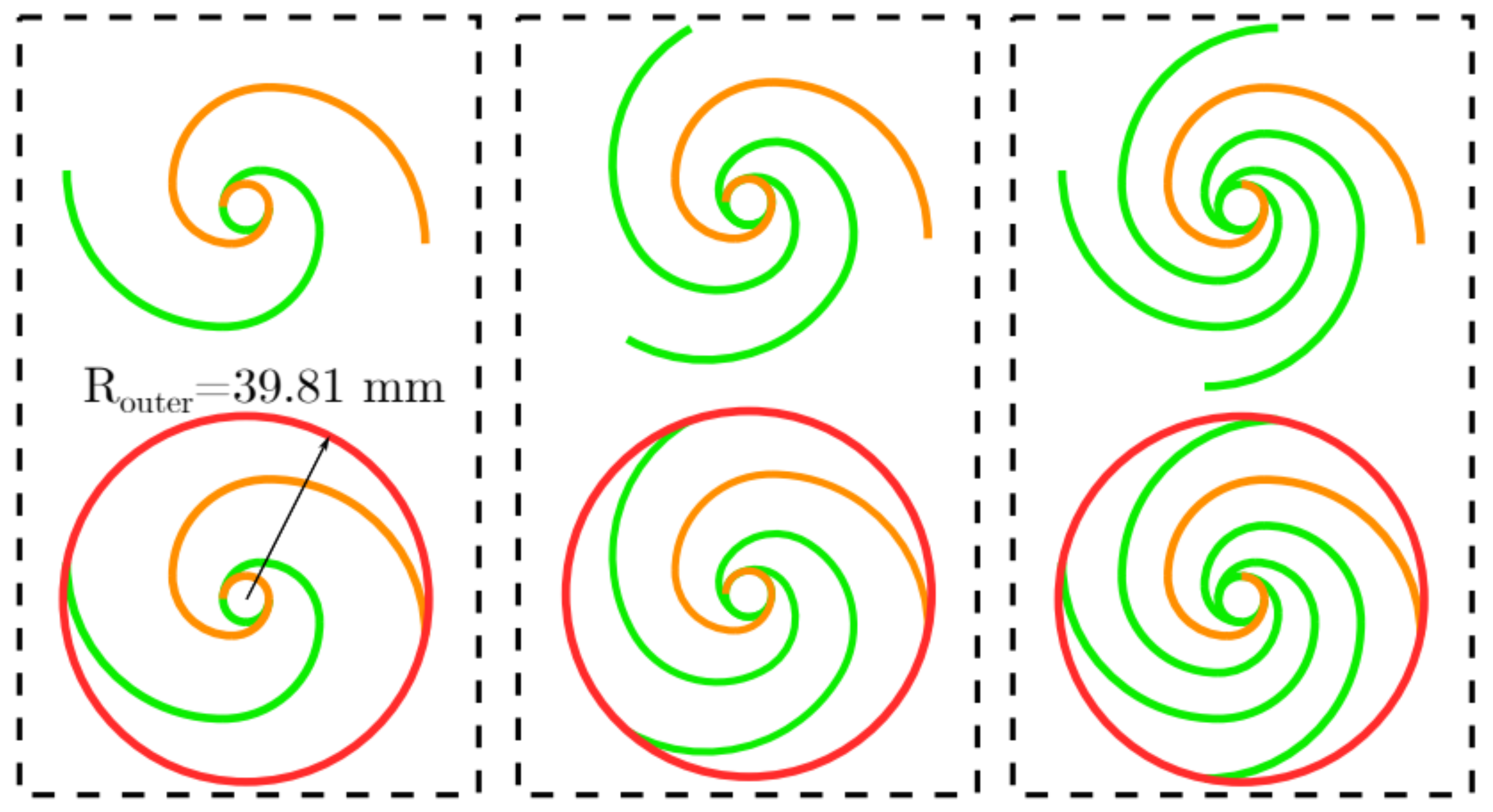
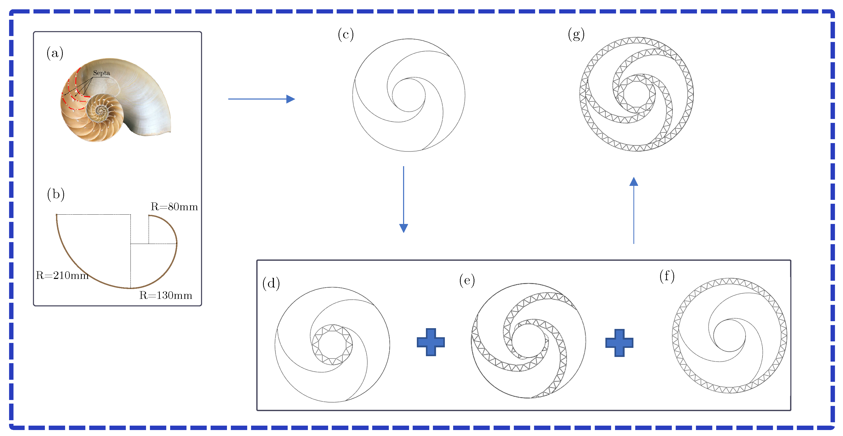
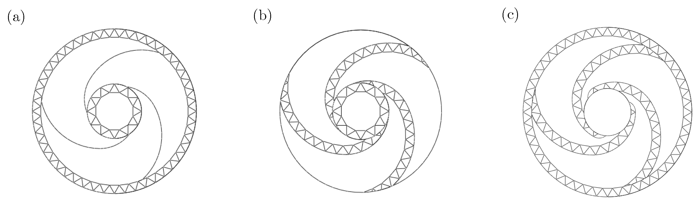
2.1. Bio-Inspired Nautilus Structure Design

The nautilus shell is the iconic image for a logarithmic spiral, which is similar to the Fibonacci spiral (Figure 3a). Inspired by the nautilus shell, a standard Fibonacci spiral initiates with an 80 mm radius arc and expands to a 210 mm radius arc, as shown in Figure 3b. A circular array of the illustrated spiral in Figure 3b is created around the arc’s center of the 80-millimeter-radius arc, to obtain a triple spiral image. Subsequently, a circle with radius of 80mm at the center and an outer circle with radius of 272.03 mm are constructed, intersecting with the endpoints of all the spirals. The obtained initial nautilus bionic hierarchical multi-cell (NBHMC) structure is shown in Figure 3c. To further enhance crashworthiness, a nautilus bionic double hierarchical multi-cell (NBDHMC) structure is proposed, which features insets of equilateral triangles within its substructure, replacing edges in various regions. For the inner hierarchical (NBIHMC) structure, we assume that the number of triangles serves as the parameter, represented by m. The first step is to position the centers of all the equilateral triangles on the inner circle. Subsequently, by adjusting the angle between the two endpoints of each triangle’s base and the center of the inner circle, the number of triangles in the substructure is determined. A new circle is constructed intersecting with the top vertexes of all the triangles, culminating in the creation of the substructure utilized to substitute the inner circle (Figure 3d). For the outer hierarchical (NBOHMC) structure, the only distinction from NBIHMC lies in the transformation of the inner circle into the outer circle, which is shown in Figure 3f. The number of triangles in the outer circle serves as the parameter denoted by n. For the screw hierarchical (NBSHMC) structure, the side lengths of the complete triangles within the structure are a variable (Figure 3e) expressed by TH. Finally, integration of the three hierarchical structures results in the creation of the nautilus bionic integrated composite hierarchical multi-cell (NBCHMC) structure, as shown in Figure 3g.

2.2. Crashworthiness Evaluation Indicators

The evaluation of energy absorption characteristics is crucial for assessing the crashworthiness of thin-walled structures. Several common indicators are considered to quantify the crashworthiness of the structure, including the energy absorption (EA), initial peak force (IPF), specific energy absorption (SEA), mean crush force (MCF), and crush force efficiency (CFE).
EA signifies the ability of thin-walled structures to dissipate energy through plastic deformation during impact, and can be obtained through the integration of the force–displacement curve. The formula is as follows:
E A = 0 d F ( x ) d x
where d is the crushing distance and F ( x ) refers to the instantaneous axial crushing force.
The specific absorption energy (SEA) is defined as the energy absorption per unit mass, calculated as follows:
S E A = E A m
where m represents the mass of the structure.
The mean crushing force (MCF) represents the average pressure during impact and can be expressed as:
M C F = E A d
The crushing force efficiency (CFE) is determined by the ratio between MCF and IPF:
C F E = M C F I P F
A CFE value closer to 1 indicates that the structure is more effective in energy absorption, highlighting its superior crashworthiness performance.

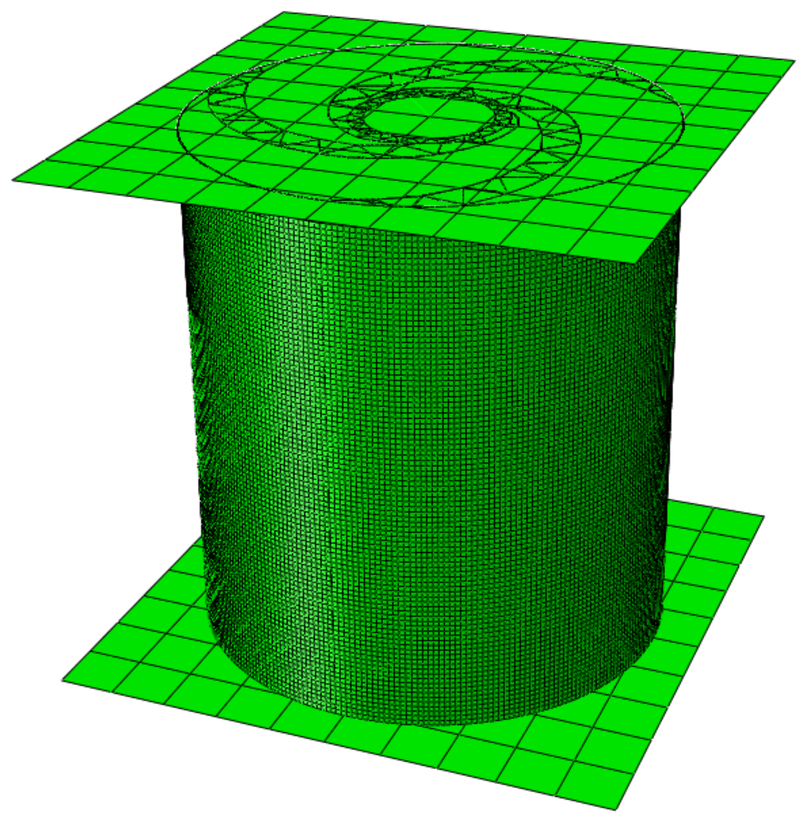
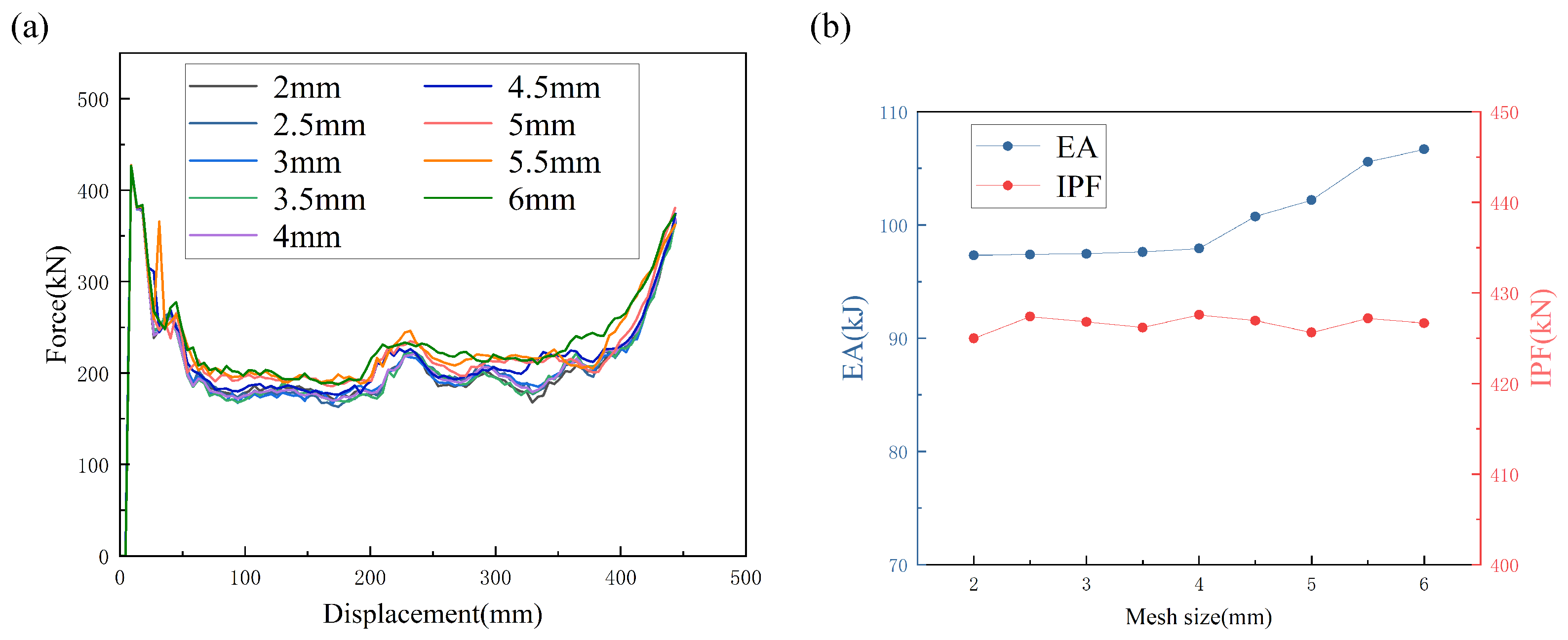
2.3. Finite Element Model Construction

Numerical models are established to explore the energy absorption characteristics of the NBDHMCs using ABAQUS/Explicit (2022, Dassault Systèmes, Providence, RI, USA). As shown in Figure 4, the bionic tube is sandwiched between two rigid plates simulated by the analytical rigid body, with a height of 600 mm. The upper rigid plate is given a mass of 1200 kg, and exerts an impact on the tube at a velocity of 60 m/s to enhance computational efficiency. The impact distance is set to 450 mm. To ensure sufficient calculation accuracy, the total kinetic energy should be much less than the total internal energy during the crushing process [42]. The lower rigid plate is connected to the tube while constraining all degrees of freedom. The tube is modeled with a shell element and meshed using the S4R shell elements. The rigid plates are meshed using the R3D4 shell elements. A general contact algorithm is used to control the contact behavior of the whole structure, and the friction factor is 0.3 .
The aluminum alloy AA6061-O is used in the simulation of tubes. A standard elastic-plastic isotropic hardening constitutive model is utilized to characterize the mechanical properties of the aluminum alloy. The experimental results reveal that the material exhibits the following properties: density ρ of 2700 kg/m3, Young’s modulus E of 70 GPa, Poisson’s ratio ν of 0.31 , initial yield stress σ y of 83.58 MPa, and ultimate stress σ u of 165.92 MPa. The true stress–plastic strain curve of the material is presented in Figure 5. The strain rate is not considered in the simulation, since AA6061-O exhibits insensitivity to the strain rate.
The mesh size significantly impacts the numerical simulation results, necessitating the selection of an NBIHMC structure with m = 16 for a mesh convergence analysis. Nine different mesh sizes were used for testing, including 2 mm, 2.5 mm, 3 mm, 3.5 mm, 4 mm, 4.5 mm, 5 mm, 5.5 mm, and 6 mm. The numerical simulation results are shown in Figure 6 and Table 1. From the results, it can be observed that the force–displacement curves with mesh sizes from 2 mm to 4 mm almost overlap, and their EA differences are all less than 1 % . The EA difference between 5 mm and 2 mm is around 5 % , and in order to balance the computational efficiency with the computational accuracy, the mesh size for the subsequent numerical simulations is selected to be 5 mm. The reliability of this finite element model was verified experimentally in our previous work [41]. It is worth noting that the localized folding patterns observed in compression experiments are often affected by small geometric defects introduced during the manufacturing process. These defects, such as slight wall thickness variations or surface defects, are difficult to characterize and replicate in simulation models. Therefore, while our model reliably captures the overall response, some variations in localized fold formation are expected and do not affect the validity of the overall conclusions.

3. Crashworthiness Analysis

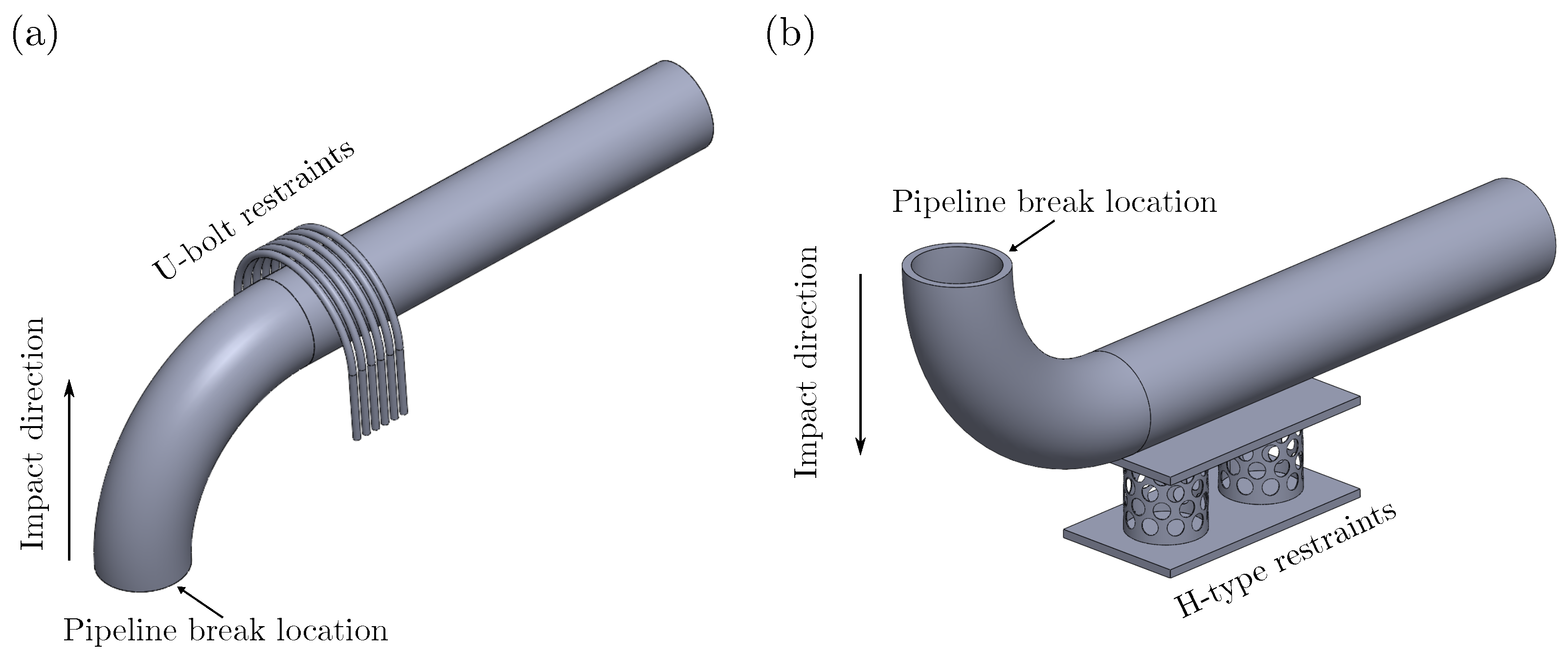
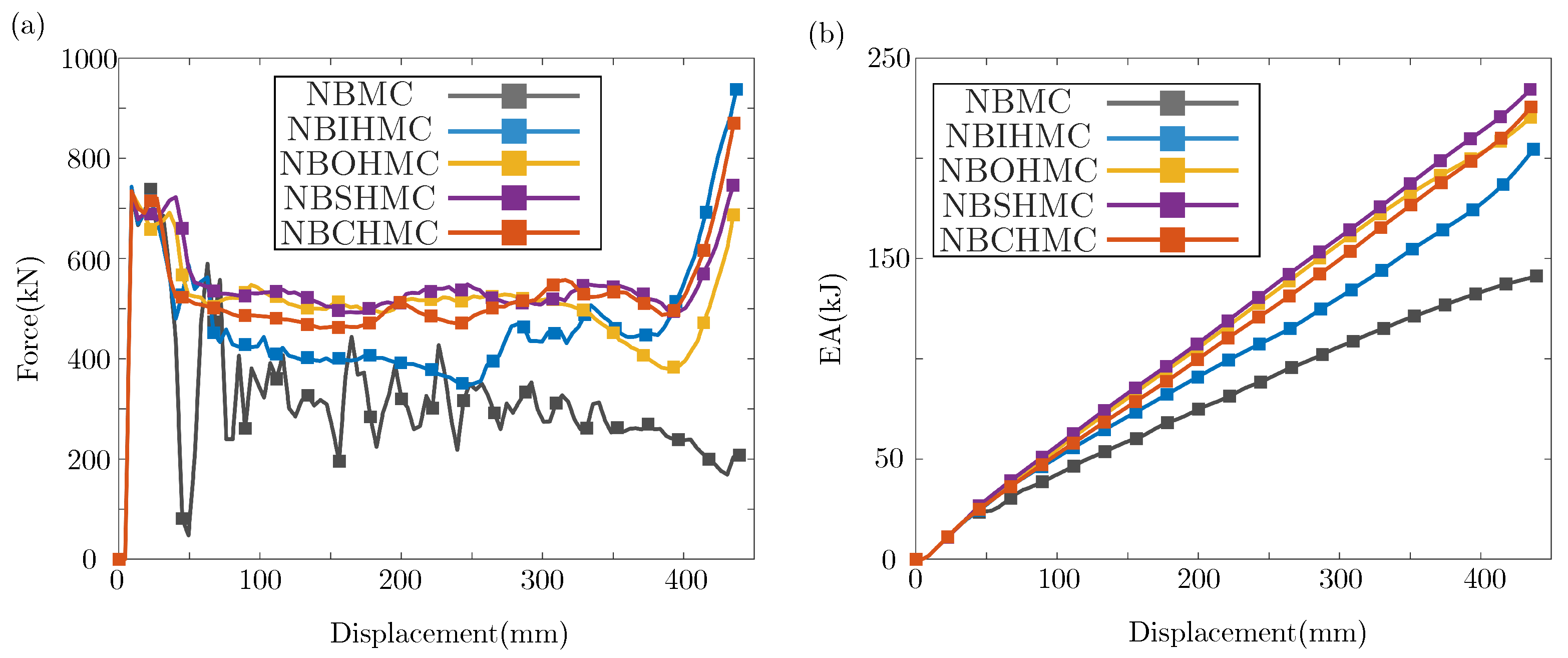
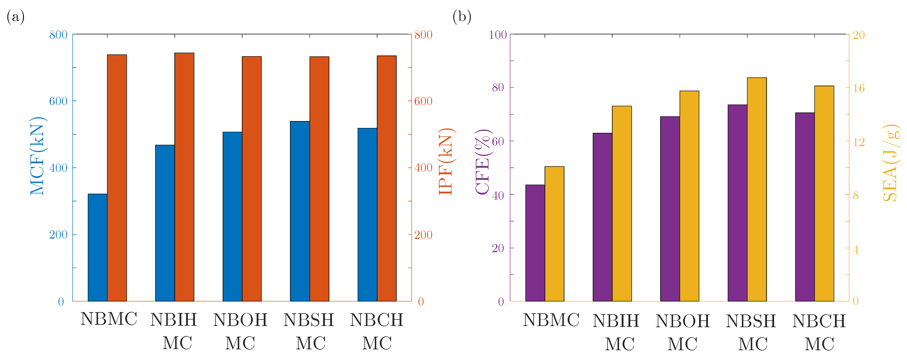
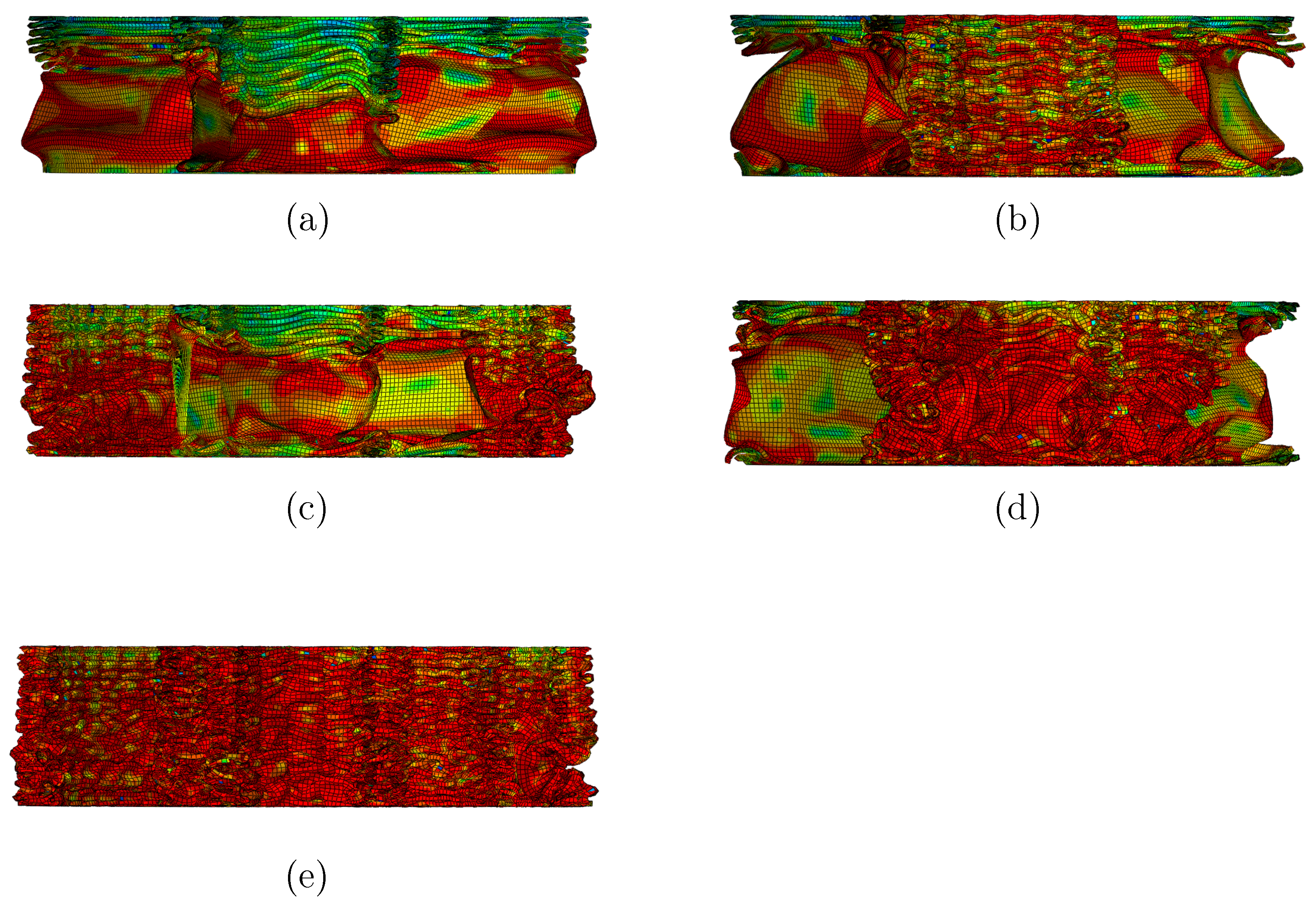
3.1. Crashworthiness Analysis Under Axial Impact

In this section, a preliminary analysis is conducted on the crashworthiness of five bionic structures under the same mass (14 kg). The parameter settings for the five structures are depicted in Figure 7. Various model parameters and crashworthiness parameters for the five structures are presented in Table 2. The force–displacement curves and energy absorption curves of the structures are shown as Figure 8. From the force–displacement curves, the IPF of the five structures shows minimal variation. There are significant differences in the plateau forces. Compared to NBHMC, the plateau force of the three hierarchical structures exhibits a significant improvement, and the remaining three hierarchical structures demonstrate slightly greater strength than NBIHMC. NBSHMC exhibits the highest plateau force. The results reveal that NBSHMC demonstrates the highest EA, surpassing NBCHMC by 3.87 % , and surpassing NBOHMC by 5.92 % . The EA is the integral of force over displacement, meaning the plateau force directly determines the EA growth rate. Thus, NBCHMC’s elevated plateau force leads to its optimal EA performance. This correlation explains why force fluctuations (e.g., IPF) minimally affect EA, whereas sustained plateau forces dominate cumulative energy absorption.
Figure 9 illustrates the comparison of the crashworthiness parameters between bionic structures. Figure 9a is a comparison between IPF and MCF. The maximum IPF occurs at NBIHMC for 743.311 kN, and the minimum IPF is observed at NBSHMC, with a small difference of 1.49 % between them. Figure 9b is a comparison between SEA and CFE. SEA exhibits a growth trend similar to MCF under the same mass, and CFE also has the same growth trend as MCF due to the small difference in IPF. Therefore, the crashworthiness of several structures can be judged by solely comparing MCF. The MCF of NBIHMC and NBOHMC was 40.45 % and 51.22 % higher than that of NBDHMC, respectively.
Figure 10 presents the deformed shapes and vertical cross-sections of five structures following compression. This can be used to explain the different MCF of the several structures. For NBHMC, the wrinkles are not entirely flattened, with unfolded sections appearing at various positions, which indicates that NBHMC is not fully compressed. For NBIHMC and NBOHMC, certain sections of the structure demonstrate folding, and others exhibit overall buckling. This indicates that the structures have entered the densification stage. The folding wavelength and number of folds are critical factors influencing the energy absorption efficiency of thin-walled structures. More folds and shorter wavelength lead to greater energy absorption capability. Contrasting NBIHMC and NBOHMC, as depicted in Figure 10, the number of folds appears similar. The folds of NBIHMC are concentrated in the inner tube, while the folds of NBOHMC are concentrated in the outer tube. The cross-sectional area of the inner tube is smaller than the outer tube. Consequently, NBOHMC exhibits better EA and MCF. The MCF of NBSHMC and NBCHMC was 67.59 % and 61.14 % higher than that of NBHMC, respectively. By contrast, Figure 10d,e reveal that the number of folds of NBSHMC is substantially fewer compared to NBCHMC. The reason is that the distinct deformation modes at adjacent locations interact with each other [43].

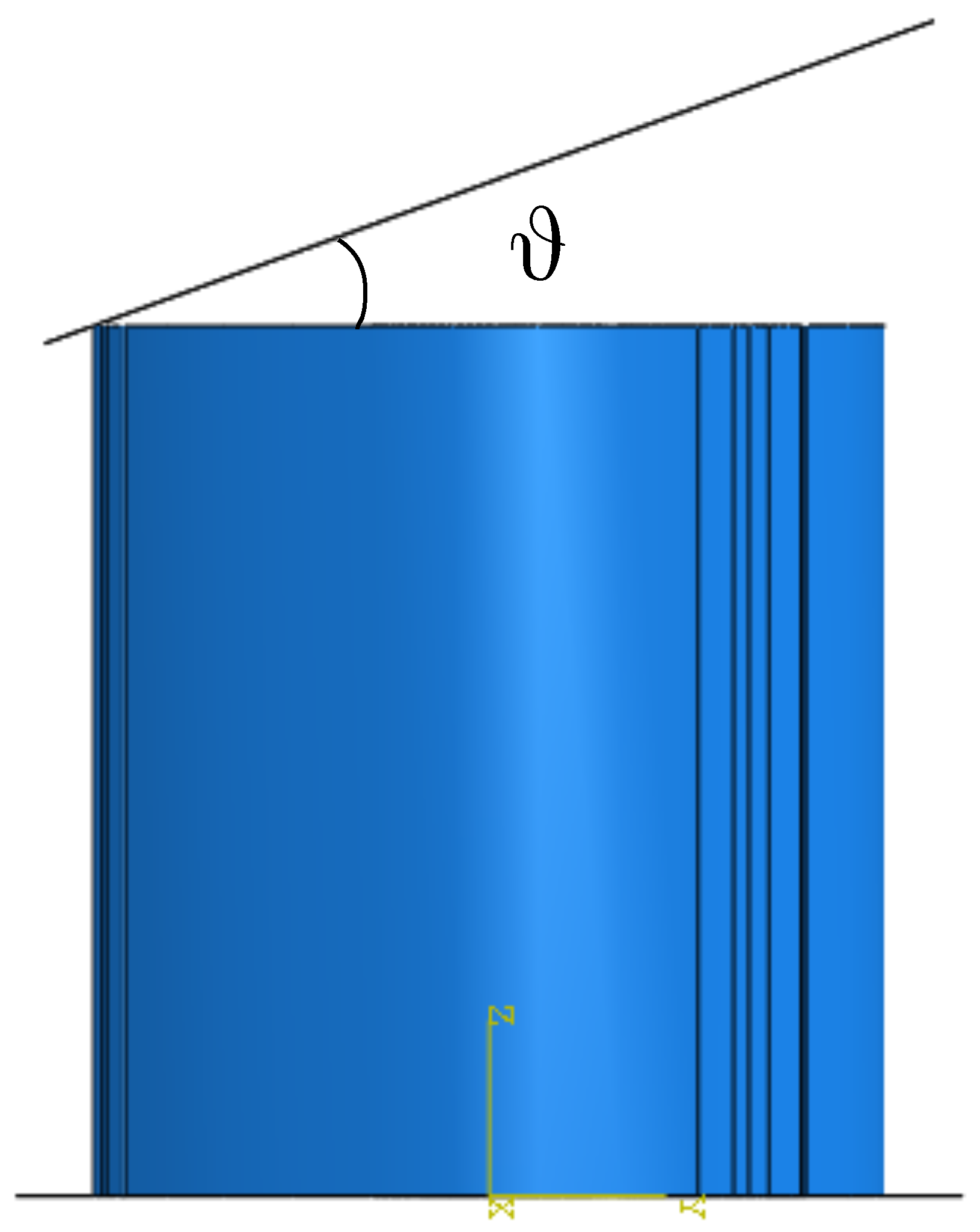
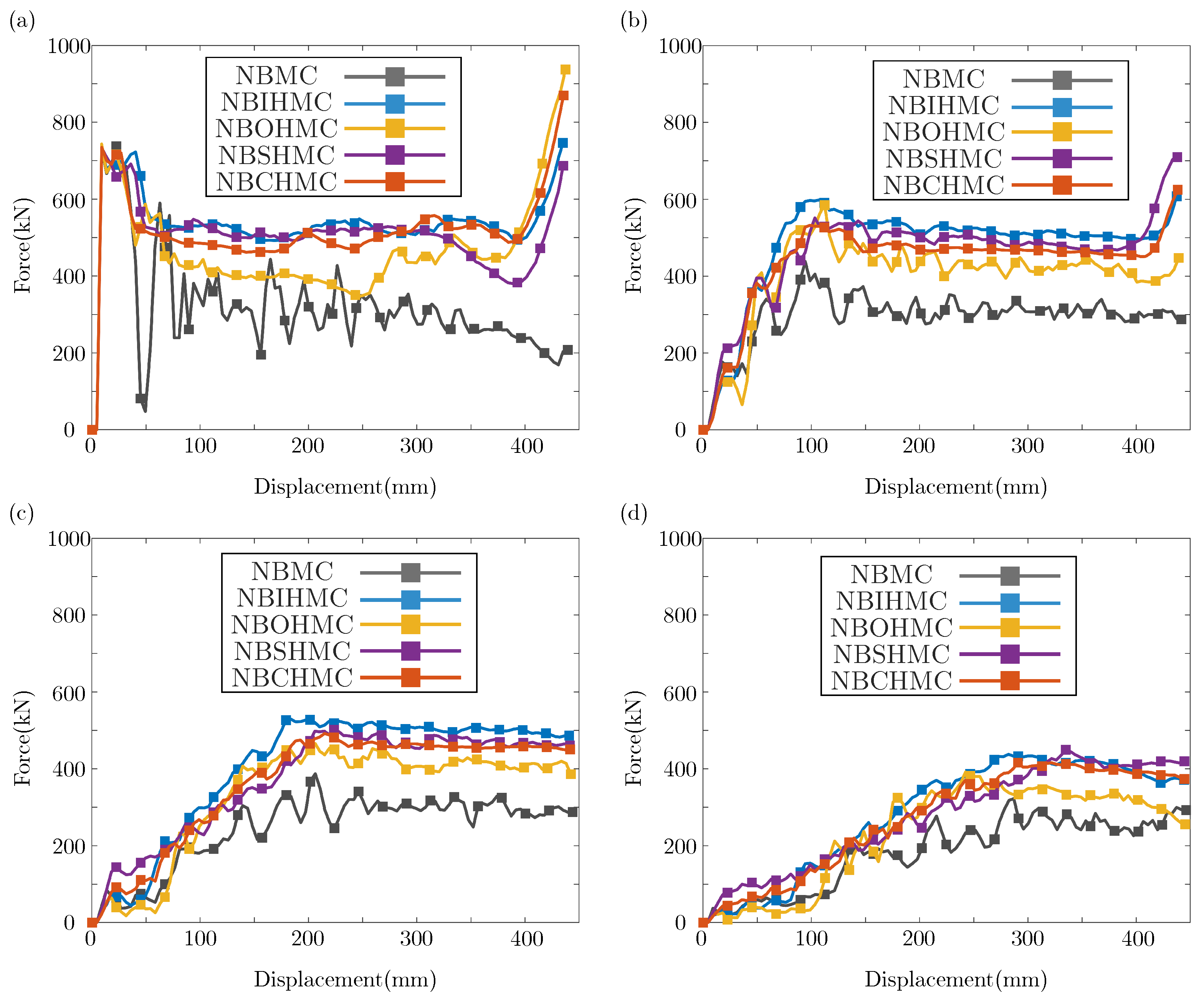
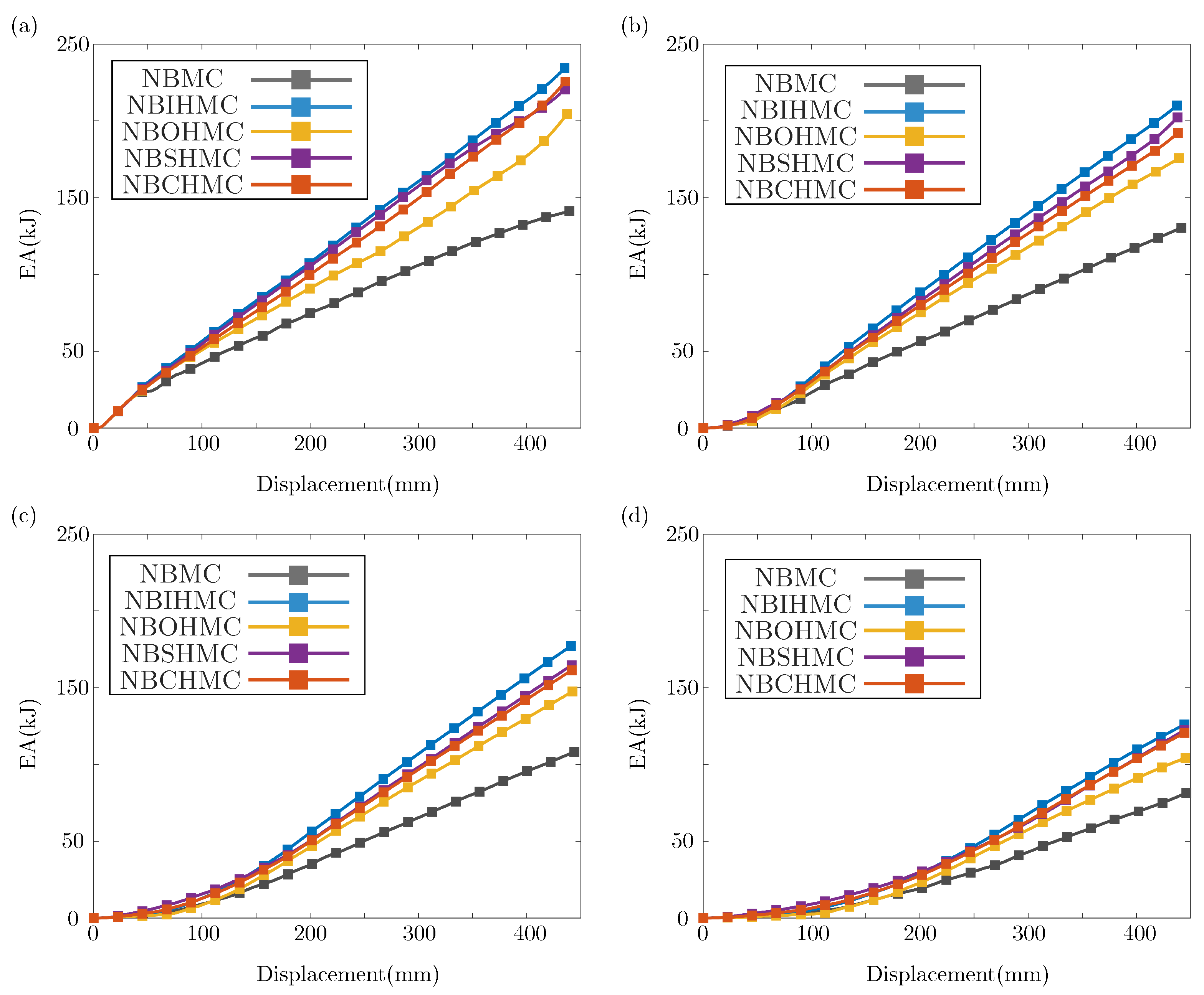
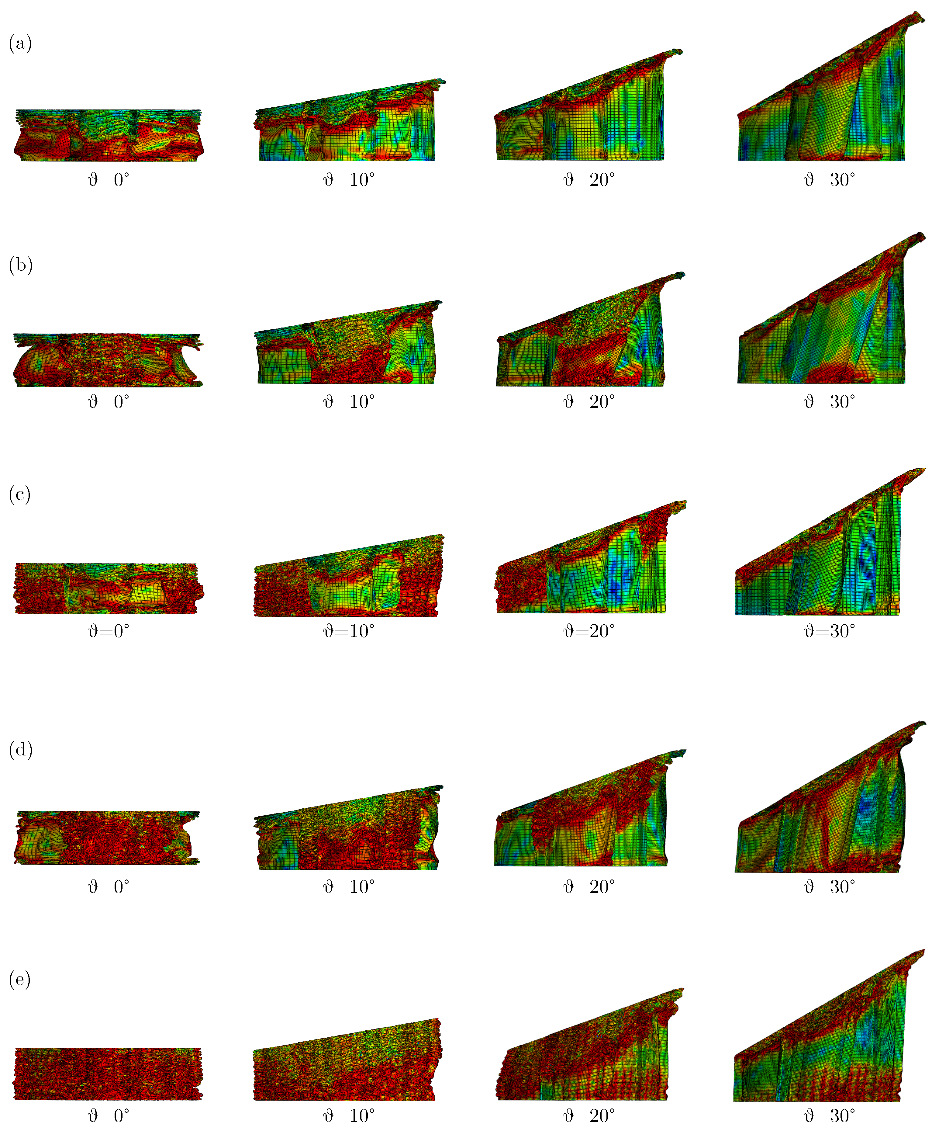
3.2. Crashworthiness Analysis Under Oblique Impact

The energy absorber is likely to experience oblique loading in a genuine shock scenario. Therefore, the focus of this section lies on the crashworthiness of thin-walled tubes subjected to multiple angular loads. Breaking angles θ of 0 , 10 , 20 , and 30 are selected to represent the axial and oblique loads. The numerical model depicting multiple loads is shown as Figure 11.
Figure 12 displays the force–displacement curves for various structures experiencing an oblique impact. It can be observed that the breaking force of the bionic structures decreases gradually with increasing breaking angle. The force–displacement curve depicted in Figure 12d lacks an obvious plateau stage, indicating that the IPF is consistently achieved throughout the entire crushing process under 30 impact. The energy absorption curve of the structures is shown as Figure 13. As can be seen, the energy absorption capacity of all the structures decreases with increase in the breaking angle. It is noticeable that NBSHMC, NBOHMC, and NBCHMC exhibit similar energy absorption capacities. The crashworthiness of the structure under multiple loads is shown as Figure 14, showing a consistent downward trend across all crashworthiness metrics except CFE as the breaking angle increases. This phenomenon occurs due to the transform in the deformation mode of all structures as the breaking angle increases.
Figure 15 presents the deformation modes of the bionic structures under axial and oblique load conditions. It is found from Figure 15 that under a small angle impact, the structures exhibit the mixed deformation mode primarily characterized by folding deformation. However, under a large angle impact, it transforms into the deformation mode with global buckling. It is well known that dissipation of the plastic deformation resulting from overall bending is less effective compared to the folding deformation mechanism.

4. Parametric Analysis

4.1. Effect of Hierarchical Portion Combination Mode

It has been elucidated in the previous sections that NBDHMC has superior energy absorption capacity compared with NBHMC. This section mainly considers the influence of the hierarchical portion combination mode on the crashworthiness of the structure. Three basic hierarchical structures are combined in pairs to obtain different composite structures, namely, NBIOHMC, NBISHMC, and NBOSHMC, as shown in Figure 16.
The combined structures are designed with different wall thicknesses to achieve the same mass (14 kg). Figure 17 presents the force–displacement curves and energy absorption curves of the combined structure and the previous structures. From Figure 17a, the IPF of all structures is very similar. With the exception of NBIHMC and NBHMC, the plateau force remains consistent across the other structures. From Figure 17b, with the exception of NBIHMC and NBHMC, the energy absorption curves for the others are similar. Particularly, the energy absorption curves of NBISHMC and NBSHMC closely align and represent optimal performance. The model parameters and crashworthiness parameters of the combined structures are displayed in Table 3. By comparing Table 2 and Table 3, the influence of the hierarchical portion combination mode can be explored. The plots show that the crashworthiness parameters of NBIOHMC and NBOSHMC are lower following combination, whereas those of NBISHMC are higher. The phenomenon indicates that the presence of the outer hierarchical portion exerts a negative effect on the other hierarchical components. Notably, NBISHMC exhibits the highest energy absorption capacity. It is reasonable to assume that the hierarchical structure formed by the combination of the inner tube and spiral portion represents the most rational configuration. However, the crashworthiness of NBSHMC closely resembles that of NBISHMC. Therefore, other factors, such as cost, can be considered in practical applications to choose between them.

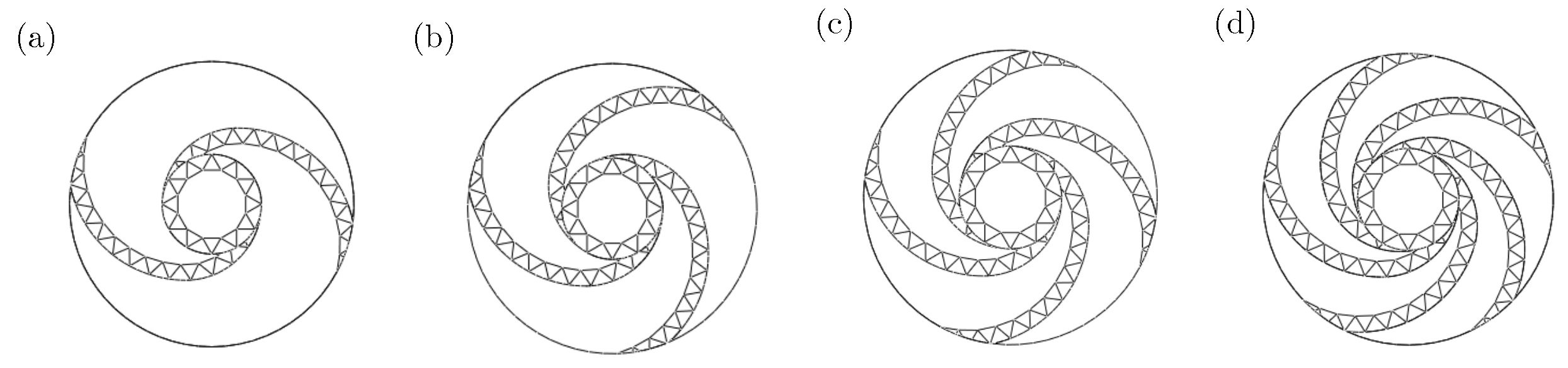
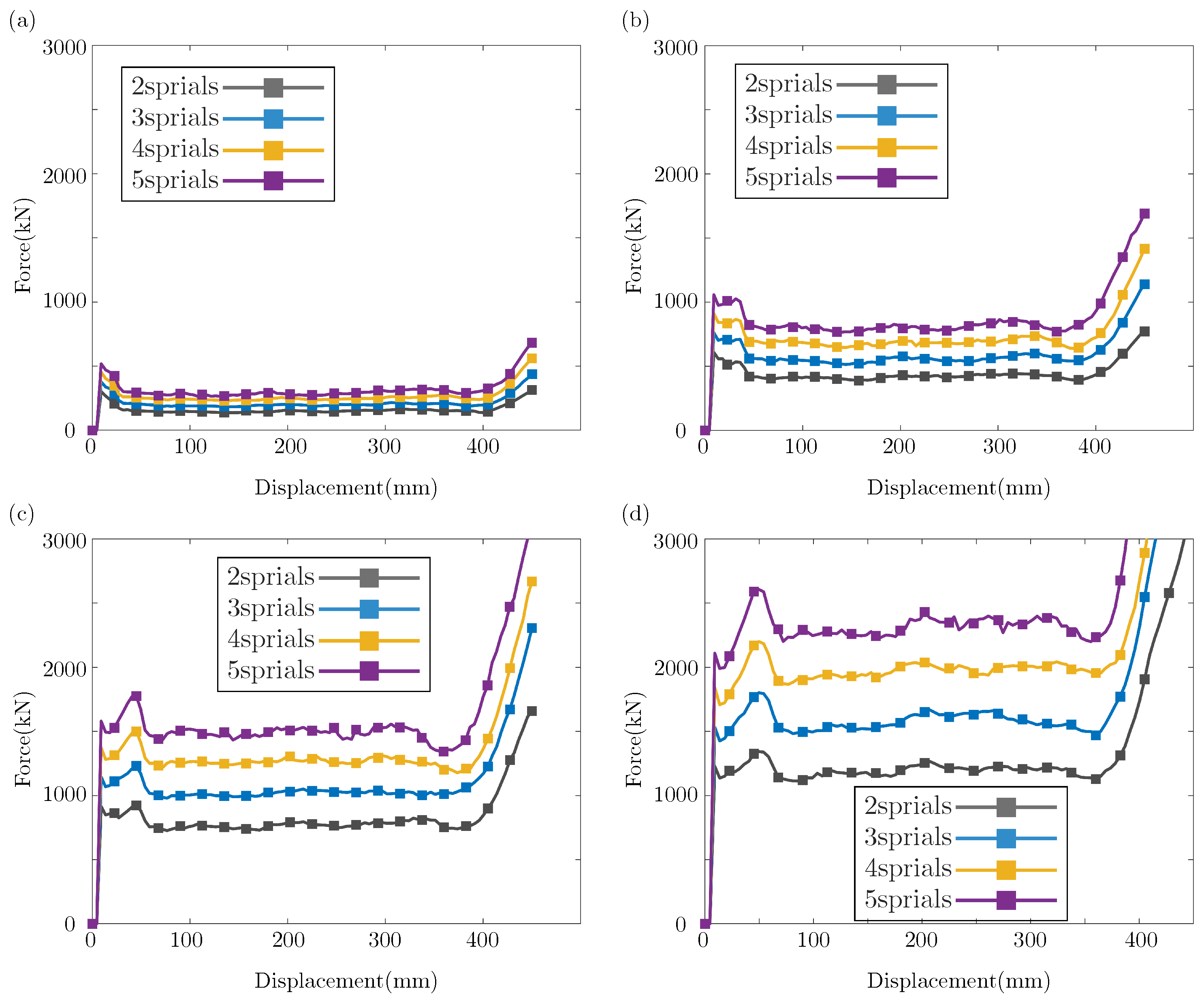
4.2. Effect of Hierarchical Level

Through investigation of the hierarchical combination, the optimal combination mode was determined. In this section, the influence of the hierarchical level on the crashworthiness of NBISHMC will be analyzed. As shown in Figure 18, the hierarchical level is delineated by the spiral number S ( 2 , 3 , 4 , 5 ), resulting in a total of four structures. To avoid the influence of wall thickness variation, the wall thickness of all structures is set as 0.5 mm, 1 mm, 1.5 mm, and 2 mm. The detailed structural parameters and crashworthiness of NBISHMCs are presented in Table 4. Figure 19 and Figure 20 show the force–displacement curves and energy absorption curves of NBISHMCs of different hierarchical levels. The plots show that both the plateau force and the energy absorption increase with the spiral number and increase in the wall thickness. Figure 21 and Table 4 summarize the detailed crashworthiness analysis data of NBISHMC. From Figure 21, the four crashworthiness parameters all increase with increase in the spiral number and the wall thickness. However, an excessively high IPF is detrimental to the energy absorption of the structure. Therefore, in structural design, the appropriate selection of wall thickness and spiral number is crucial to achieving high SEA, MCF, and CFE, while maintaining a low IPF.

4.3. Effect of Bionic Hierarchical Cross-Section Characteristics

In Section 2.1, the cross-section characteristics of different NBHMCs were delineated. For NBISHMC, its cross-section characteristics are divided into two aspects: the number of inner tube triangles m and the spiral tube triangle height TH. Based on the three spirals bionic structure ( S = 3 ), nine cross-sectional configurations are obtained by adjusting the count of inner tube triangles and the spiral tube triangle height, as shown in Figure 22.
The force–displacement curve and energy absorption of NBISHMCs with different cross-section characteristics are shown in Figure 23 and Figure 24. The plots show that as the height of the spiral tube triangle increases, the plateau force increases significantly, leading to an enhanced energy absorption capacity. Maintaining a constant value for m, the energy absorption capacity of the structure decreases as the spiral tube triangle height increases. This phenomenon arises from the increase in m and the decrease in TH, which lead to the generation of more deformation folds, thereby enhancing the energy absorption capacity.
The detailed crashworthiness parameters of NBISHMC are summarized in Figure 25 and Table 5. From Figure 25, when the TH remains constant, a large m can cause an increase in the crashworthiness parameters, such as SEA and IPF. Conversely, with m held constant, an increase in TH results in a reduction in the crashworthiness parameters. However, it is noteworthy that when the m value attains a value of 24, the rise in TH significantly alters IPF, causing a subsequent increase in CFE. Therefore, considering the need to enhance energy absorption and decrease the initial peak crushing force, it is advisable to select a moderate value for m and TH to achieve a balance.

5. Conclusions

Based on the nautilus bionic hierarchical multi-cell structure, a novel double hierarchical structure, substituting sides with substructures containing triangles, named NBDHMC, is obtained. A comprehensive numerical simulation study is carried out to examine the crashworthiness of the bionic thin-walled tubes under axial impact and oblique impact. The conclusions are as follows:
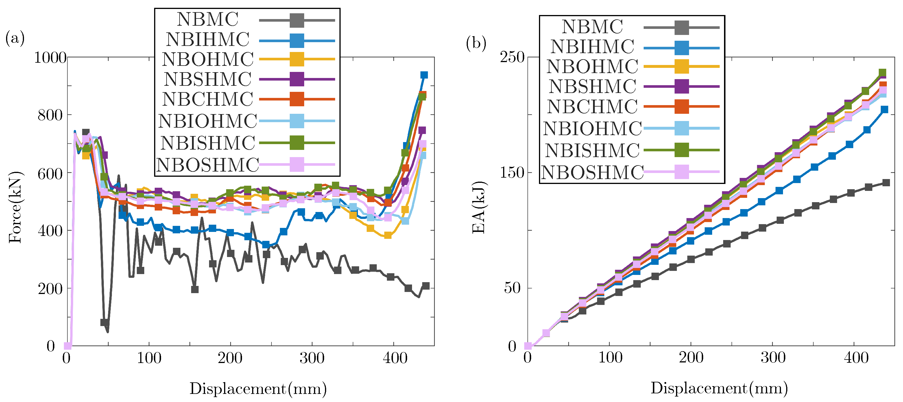
  • Compared with hollow tubes and NBDHMCs, several NBDHMCs have shorter wavelengths and more folds under pressure, and exhibit better energy absorption capacity. Among them, NBSHMC exhibits the highest CFE of 73.56 % . Under the action of an oblique impact, the deformation mode of the structure changes and the energy absorption capacity decreases;
  • Considering the hierarchical portion combination mode, three structural forms were added for comparison, and the optimal structure was finally confirmed as NBISHMC;
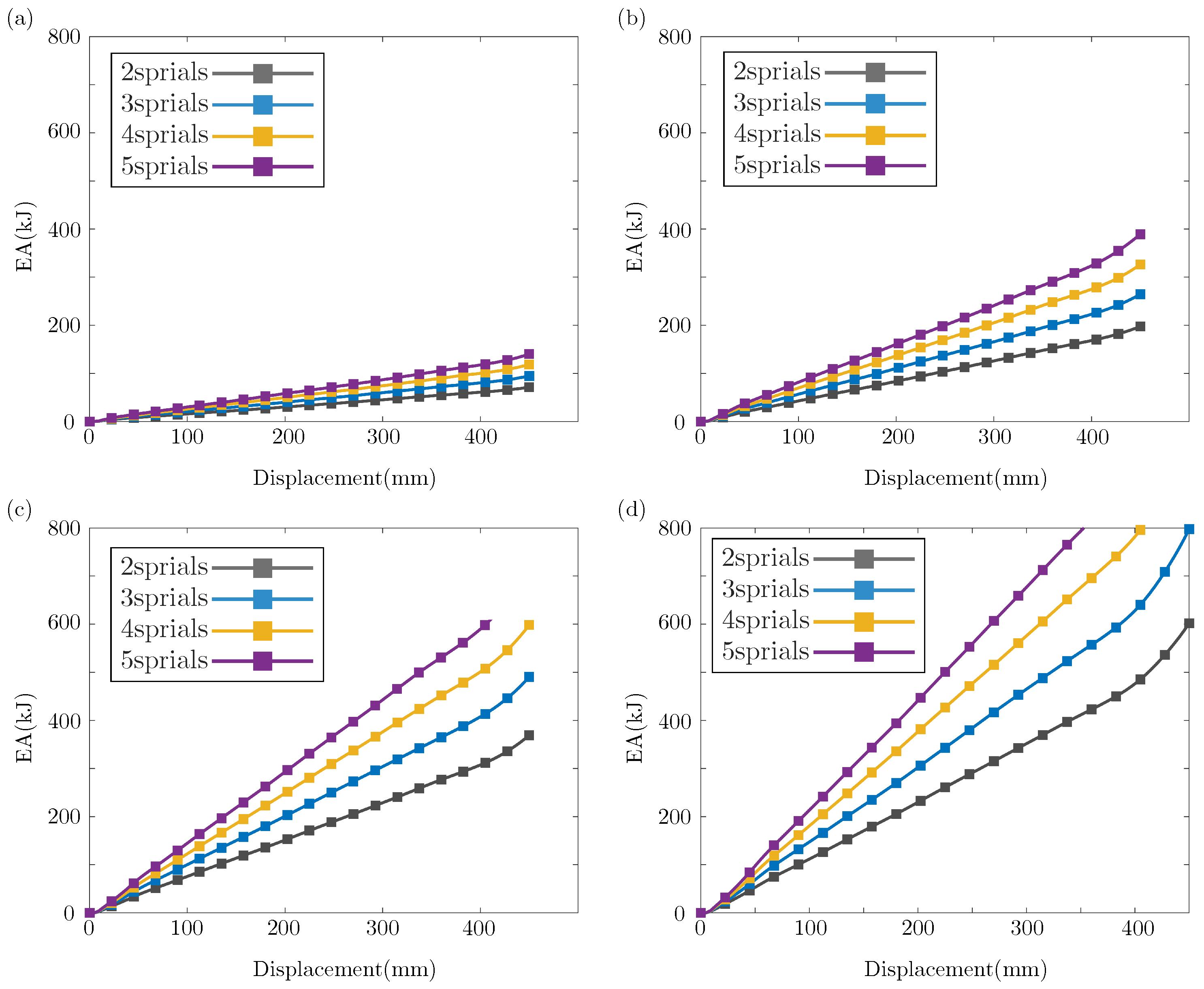
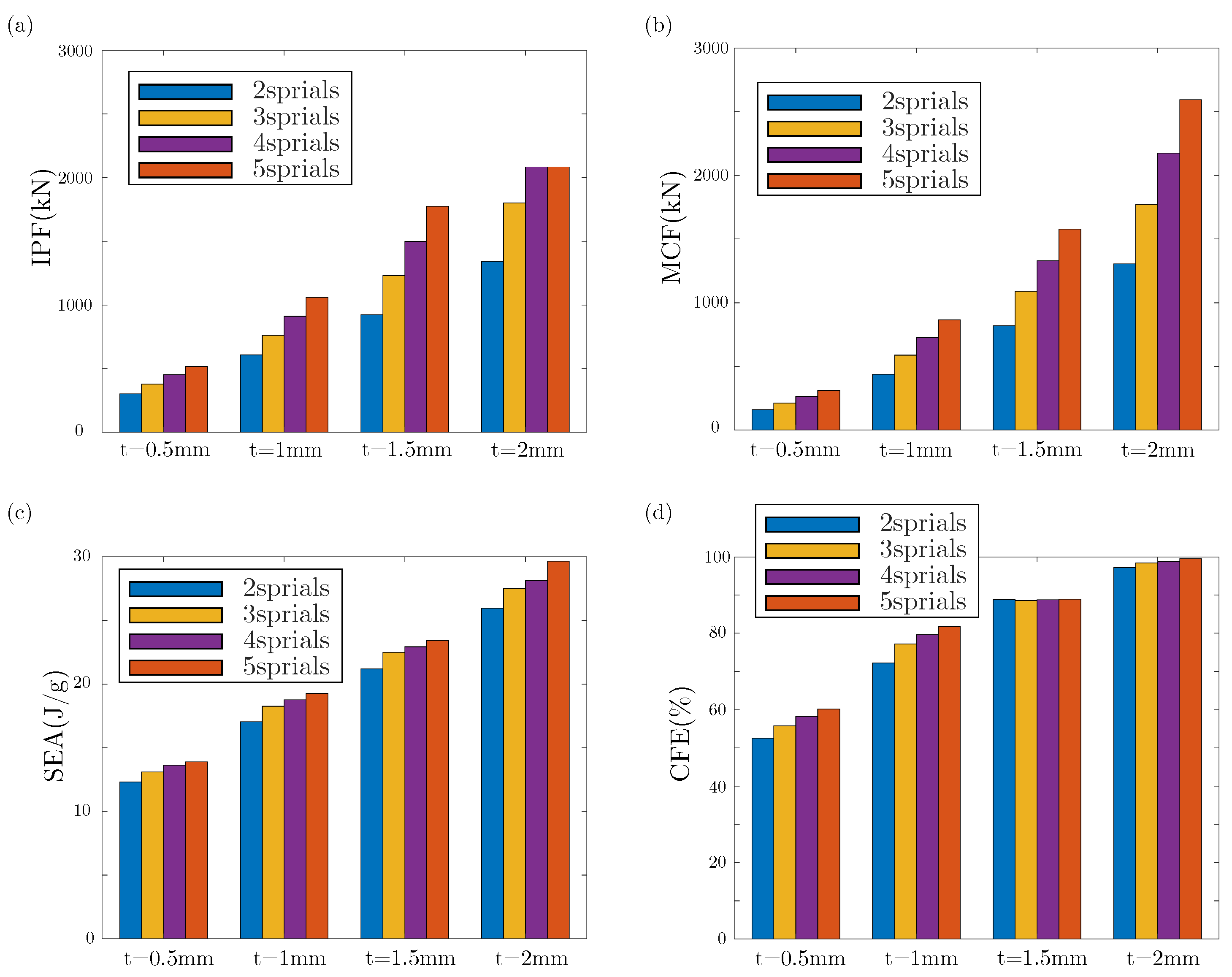
  • Parametric investigation results indicate that with increase in S and t, the crashworthiness parameters of the thin-walled structures, such as SEA, MCF, CFE, and IPF, increased significantly. Therefore, in order to maintain high SEA and low IPF, it is necessary to choose a reasonable t and S;
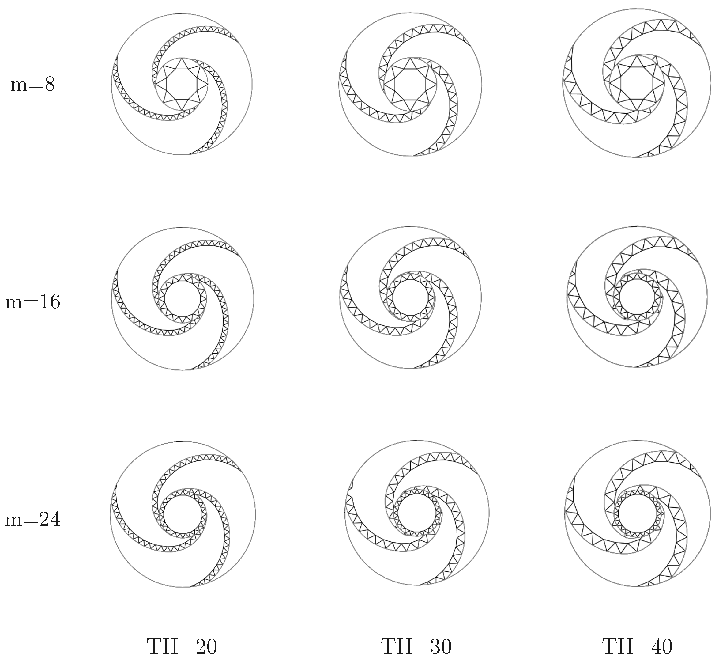
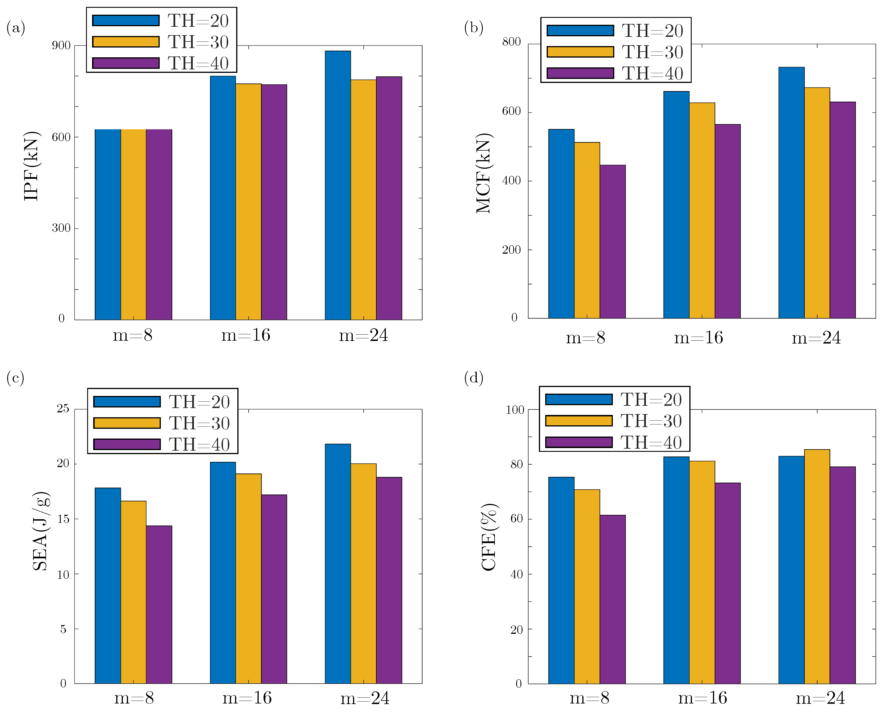
  • By changing m and TH under the condition of equal wall thickness, it was found that when m increases and TH decreases, the four crashworthiness parameters are improved. However, an increase in TH leads to an increase in CFE when the m value reaches 24.

Author Contributions

Z.H.: Writing—original draft, validation, methodology, investigation, formal analysis, data curation, conceptualization; Y.Y.: writing—review and editing, validation, software, resources, methodology, investigation; L.H.: Writing—review and editing, visualization, validation, software; S.G.: Writing—review and editing, validation, supervision, methodology. All authors have read and agreed to the published version of the manuscript.

Funding

This research was funded by the Young Excellence Programme of China National Nuclear Corporation.

Institutional Review Board Statement

Not applicable.

Informed Consent Statement

Not applicable.

Data Availability Statement

Data will be made available on request.

Acknowledgments

The authors are grateful for the financial support from the Young Excellence Programme of China National Nuclear Corporation (CNNC).

Conflicts of Interest

Author Zheng He was employed by the company Chinergy Co., Ltd. The remaining authors declare that the research was conducted in the absence of any commercial or financial relationships that could be construed as a potential conflict of interest. The authors declare that this study received funding from China National Nuclear Corporation. The funder was not involved in the study design, collection, analysis, interpretation of data, the writing of this article or the decision to submit it for publication.

References

  1. Dundulis, G.; Uspuras, E.; Kulak, R.F.; Marchertas, A. Evaluation of pipe whip impacts on neighboring piping and walls of the Ignalina Nuclear Power Plant. Nucl. Eng. Des. 2007, 237, 848–857. [Google Scholar] [CrossRef]
  2. Pate, S.B.; Solomon, I.S.M.; Dundulis, G.; Griskevicius, P. Applications of the FEM to pipe whip analysis using coupled modelling technique. Nucl. Eng. Des. 2024, 418, 112941. [Google Scholar] [CrossRef]
  3. Wang, Y.; Hu, J.; Wang, X.; Wu, S. Dynamic analysis of whipping behavior induced by the circumferential fracture of high energy pipes considering fluid-structure interaction effect. Int. J. Press. Vessels Pip. 2024, 212, 105336. [Google Scholar] [CrossRef]
  4. Hu, J.; Wang, X.; Li, Y.; Wen, X.; Wu, Y.; Huang, Y. Investigation of whipping effect on high energy pipe based on fluid-structure interaction method. Int. J. Impact Eng. 2023, 173, 104463. [Google Scholar] [CrossRef]
  5. Shi, L.; Lu, Y.; Peng, L.; Qiao, J.; Zhang, R.; Sun, T. Antiwhip Measures for High-Energy Piping in Nuclear Power Plants Using Lead Extrusion Impact Damping Devices: Tests and Simulations. Struct. Control Health Monit. 2025, 2025, 8829452. [Google Scholar] [CrossRef]
  6. Luo, X.; Wang, S.; Wang, J.; Wang, P.; Wang, Y.; Zhao, W. Analysis of whipping effect on high energy pipe in a nuclear power plant. Fusion Eng. Des. 2020, 150, 111359. [Google Scholar] [CrossRef]
  7. Zhang, X.; Cao, F.; Ding, Y.; Wang, J.; Fang, J. Load analysis of hypothetical ruptures and optimum design of H-type anti-whip restraint devices for high energy pipes based on bilinearity method. Nucl. Power Eng. 2011, 32, 64–68. [Google Scholar]
  8. Olabi, A.G.; Morris, E.; Hashmi, M. Metallic tube type energy absorbers: A synopsis. Thin-Walled Struct. 2007, 45, 706–726. [Google Scholar] [CrossRef]
  9. Xing, J.; Xu, P.; Yao, S.; Zhao, H.; Zhao, Z.; Wang, Z. Study on the layout strategy of diaphragms to enhance the energy absorption of thin-walled square tubes. Structures 2021, 29, 294–304. [Google Scholar] [CrossRef]
  10. Xie, S.; Chen, P.; Wang, N.; Wang, J.; Du, X. Crashworthiness study of circular tubes subjected to radial extrusion under quasi-static loading. Int. J. Mech. Sci. 2021, 192, 106128. [Google Scholar] [CrossRef]
  11. Liu, J.; Chen, W.; Hao, H.; Wang, Z. In-plane crushing behaviors of hexagonal honeycombs with different Poisson’s ratio induced by topological diversity. Thin-Walled Struct. 2021, 159, 107223. [Google Scholar] [CrossRef]
  12. Sun, D.; Zhang, W. Energy absorption performance of staggered triangular honeycombs under in-plane crushing loadings. J. Eng. Mech. 2013, 139, 153–166. [Google Scholar] [CrossRef]
  13. Zhang, H.; Zhang, X. Crashworthiness performance of conical tubes with nonlinear thickness distribution. Thin-Walled Struct. 2016, 99, 35–44. [Google Scholar] [CrossRef]
  14. Li, X.; Yin, Y.; Zhu, X.; Wang, R.; Li, T.; Zhang, Q.; Li, W. Performance of hollow and aluminum foam-filled multi-cell thin-walled aluminum alloy tubes (6063-T5) under axial impact. Structures 2023, 47, 1803–1821. [Google Scholar] [CrossRef]
  15. Mozafari, H.; Khatami, S.; Molatefi, H.; Crupi, V.; Epasto, G.; Guglielmino, E. Finite element analysis of foam-filled honeycomb structures under impact loading and crashworthiness design. Int. J. Crashworthiness 2016, 21, 148–160. [Google Scholar] [CrossRef]
  16. Li, Q.; Jia, X.; Ye, X.; Tan, H.; Wang, F.; Hu, L. Axial compression property of a novel dendritic lattice structure. Mater. Today Commun. 2025, 46, 112668. [Google Scholar] [CrossRef]
  17. Zhang, Y.; Ge, P.; Lu, M.; Lai, X. Crashworthiness study for multi-cell composite filling structures. Int. J. Crashworthiness 2018, 23, 32–46. [Google Scholar] [CrossRef]
  18. Latifzadeh, F.; Keshavarzi, A.; Saeidi Googarchin, H. Crashworthiness of adhesively bonded bio-inspired AL/CFRP hybrid tubes under lateral loading. In Mechanics of Advanced Materials and Structures; Taylor: Abingdon, UK, 2025; pp. 1–18. [Google Scholar]
  19. Wei, Y.; Yang, Z.; Yan, H.; Guo, Y.; Wu, X.; Huang, C. Proactive regulation of axial crushing behavior of thin-walled circular tube by gradient grooves. Int. J. Mech. Sci. 2016, 108, 49–60. [Google Scholar] [CrossRef]
  20. Wang, H.; Fu, Y.; Su, M.; Hao, H. Effect of structure design on compressive properties and energy absorption behavior of ordered porous aluminum prepared by rapid casting. Mater. Des. 2019, 167, 107631. [Google Scholar] [CrossRef]
  21. Deng, X.; Qin, S.; Huang, J. Multiobjective optimization of axially varying thickness lateral corrugated tubes for energy absorption. Mech. Adv. Mater. Struct. 2022, 29, 4259–4272. [Google Scholar] [CrossRef]
  22. Gong, C.; Bai, Z.; Wang, Y.; Zhang, L. On the crashworthiness performance of novel hierarchical multi-cell tubes under axial loading. Int. J. Mech. Sci. 2021, 206, 106599. [Google Scholar] [CrossRef]
  23. San Ha, N.; Pham, T.M.; Hao, H.; Lu, G. Energy absorption characteristics of bio-inspired hierarchical multi-cell square tubes under axial crushing. Int. J. Mech. Sci. 2021, 201, 106464. [Google Scholar]
  24. Li, Z.; Ma, W.; Yao, S.; Xu, P. Crashworthiness performance of corrugation-reinforced multicell tubular structures. Int. J. Mech. Sci. 2021, 190, 106038. [Google Scholar] [CrossRef]
  25. Teng, L.; Deng, Q.; Li, X. Energy absorption and deformation modes of several thin-walled tubes under dynamic compression. Structures 2023, 54, 890–897. [Google Scholar] [CrossRef]
  26. Zhang, X.; Zhang, H. Some problems on the axial crushing of multi-cells. Int. J. Mech. Sci. 2015, 103, 30–39. [Google Scholar] [CrossRef]
  27. Xu, X.; Zhang, Y.; Chen, X.; Liu, Z.; Xu, Y.; Gao, Y. Crushing behaviors of hierarchical sandwich-walled columns. Int. J. Mech. Sci. 2019, 161, 105021. [Google Scholar] [CrossRef]
  28. Qin, R.; Wang, X.; Gao, F.; Chen, B. Energy absorption performance of hexagonal multi-cell tube with hierarchy under axial loading. Thin-Walled Struct. 2021, 169, 108392. [Google Scholar] [CrossRef]
  29. Wang, Z.; Li, Z.; Shi, C.; Zhou, W. Mechanical performance of vertex-based hierarchical vs square thin-walled multi-cell structure. Thin-Walled Struct. 2019, 134, 102–110. [Google Scholar] [CrossRef]
  30. Zhang, Y.; Chen, T.; Xu, X.; Hu, Z. Out-of-plane mechanical behaviors of a side hierarchical honeycomb. Mech. Mater. 2020, 140, 103227. [Google Scholar] [CrossRef]
  31. Tsang, H.; Raza, S. Impact energy absorption of bio-inspired tubular sections with structural hierarchy. Compos. Struct. 2018, 195, 199–210. [Google Scholar] [CrossRef]
  32. San Ha, N.; Lu, G.; Xiang, X. High energy absorption efficiency of thin-walled conical corrugation tubes mimicking coconut tree configuration. Int. J. Mech. Sci. 2018, 148, 409–421. [Google Scholar]
  33. Ufodike, C.O.; Wang, H.; Ahmed, M.F.; Dolzyk, G.; Jung, S. Design and modeling of bamboo biomorphic structure for in-plane energy absorption improvement. Mater. Des. 2021, 205, 109736. [Google Scholar] [CrossRef]
  34. Sun, G.; Liu, T.; Fang, J.; Steven, G.P.; Li, Q. Configurational optimization of multi-cell topologies for multiple oblique loads. Struct. Multidiscip. Optim. 2018, 57, 469–488. [Google Scholar] [CrossRef]
  35. Liu, H.; Zhang, E.T.; Wang, G.; Ng, B.F. In-plane crushing behavior and energy absorption of a novel graded honeycomb from hierarchical architecture. Int. J. Mech. Sci. 2022, 221, 107202. [Google Scholar] [CrossRef]
  36. Liang, H.; Wang, Q.; Pu, Y.; Zhao, Y.; Ma, F. In-plane compressive behavior of a novel self-similar hierarchical honeycomb with design-oriented crashworthiness. Int. J. Mech. Sci. 2021, 209, 106723. [Google Scholar] [CrossRef]
  37. Wu, F.; Chen, Y.; Zhao, S.; Hong, Y.; Zhang, Z.; Zheng, S. Mechanical properties and energy absorption of composite bio-inspired multi-cell tubes. Thin-Walled Struct. 2023, 184, 110451. [Google Scholar] [CrossRef]
  38. Wei, Z.; Wang, H.; Bi, Y.; Li, Y.; Li, B.; Wang, B. Crashworthiness and gradient optimization of multi-cell thin-walled structures inspired by leaf venation in royal water lily. In Mechanics of Advanced Materials and Structures; Taylor & Francis: Abingdon, UK, 2024; pp. 1–17. [Google Scholar]
  39. Li, Y.; Hu, D.; Yang, Z. Crashworthiness design of a sponge-inspired multicell tube under axial crushing. Int. J. Mech. Sci. 2023, 244, 108070. [Google Scholar] [CrossRef]
  40. Song, J.; Xu, S.; Liu, S.; Zou, M. Study on the crashworthiness of bio-inspired multi-cell tube under axial impact. Int. J. Crashworthiness 2022, 27, 390–399. [Google Scholar] [CrossRef]
  41. Hu, L.; Cong, Y.; Gu, S.; Zhang, G.; He, Z.; Feng, Z. Energy absorption characteristics of novel bionic H-type whip restraints for nuclear power plants. Nucl. Eng. Des. 2024, 424, 113243. [Google Scholar] [CrossRef]
  42. Zhu, G.; Sun, G.; Yu, H.; Li, S.; Li, Q. Energy absorption of metal, composite and metal/composite hybrid structures under oblique crushing loading. Int. J. Mech. Sci. 2018, 135, 458–483. [Google Scholar] [CrossRef]
  43. Qin, S.; Deng, X.; Liu, X. Crashworthiness analysis of bioinspired hierarchical gradient multicell tubes under axial impact. Thin-Walled Struct. 2022, 179, 109591. [Google Scholar] [CrossRef]
Figure 1. (a) Schematic of the typical main steam pipe and U-bolt restraints; (b) Schematic of the pipe and H-type restraints.
Applsci 15 05507 g001
Figure 2. Spiral design of the nautilus bionic restraint: A Nautilus bionic structure can be constructed by first drawing an initial Fibonacci spiral (orange curve), listing multiple Fibonacci spirals (green curves) based on the initial spiral circular array, and drawing a circle (red circle) tangent to the outer endpoints of all spirals.
Applsci 15 05507 g002
Figure 3. Biological structures and bio-inspired multi-cell tube cross-sections: (a) Nautilus shell, (b) Fibonacci spiral, (c) NBHMC: initial nautilus bionic hierarchical multi-cell structure, (d) NBIHMC: substructure of the inner circle, (e) NBSHMC: the screw hierarchical structure, (f) NBOHMC: the outer hierarchical structure, (g) NBCHMC: composite hierarchical multi-cell structure integrating (df).
Applsci 15 05507 g003
Figure 4. Finite element model.
Applsci 15 05507 g004
Figure 5. True stress–plastic strain curve of AA6061-O aluminum alloy.
Applsci 15 05507 g005
Figure 6. Mesh sensitivity analysis: (a) Force-displacement curves for different mesh sizes, (b) Comparison of EA and IPF for different mesh sizes.
Applsci 15 05507 g006
Figure 7. Five biomimetic structures and parameter settings: (a) NBHMC, (b) NBIHMC, m = 12, (c) NBOHMC, n = 48, (d) NBSHMC, TH = 30 mm, (e) NBCHMC.
Applsci 15 05507 g007
Figure 8. Force–displacement and energy absorption curves of tubes under the same mass: (a) force-displacement curve, (b) EA–displacement curve.
Applsci 15 05507 g008
Figure 9. Crashworthiness performances analysis under the same mass: (a) MCF and IPF; (b) SEA and CFE.
Applsci 15 05507 g009
Figure 10. Sectional views of representative lobes folding for 5 structures under the same mass: (a) NBHMC; (b) NBIHMC; (c) NBOHMC; (d) NBSHMC; (e) NBCHMC.
Applsci 15 05507 g010
Figure 11. Finite element model under oblique impact.
Applsci 15 05507 g011
Figure 12. Force–displacement of tubes under oblique loads: (a) 0 , (b) 10 , (c) 20 , (d) 30 .
Applsci 15 05507 g012
Figure 13. EA–displacement of tubes under multiple loads: (a) 0 , (b) 10 , (c) 20 , (d) 30 .
Applsci 15 05507 g013
Figure 14. Force–displacement of tubes under oblique loads: (a) SEA, (b) IPA, (c) MCF, (d) CFE.
Applsci 15 05507 g014
Figure 15. Sectional views of representative lobes folding for 5 different structures under oblique impact: (a) NBHMC, (b) NBIHMC, (c) NBOHMC, (d) NBSHMC, (e) NBCHMC.
Applsci 15 05507 g015
Figure 16. Three composite structures and parameter Settings: (a) NBIOHMC, (b) NBISHMC, (c) NBOSHMC.
Applsci 15 05507 g016
Figure 17. Force–displacement and energy absorption curves of composite structures under the same mass: (a) force–displacement curve, (b) EA–displacement curve.
Applsci 15 05507 g017
Figure 18. Cross-section of NBISHMC tubes with different hierarchical levels: (a) S = 2, (b) S = 3, (c) S = 4, (d) S = 5.
Applsci 15 05507 g018
Figure 19. Force–displacement curves of NBISHMCs with different hierarchical levels: (a) t = 0.5 mm, (b) t = 1 mm, (c) t = 1.5 mm, (d) t = 2 mm.
Applsci 15 05507 g019
Figure 20. EA–displacement curves of NBISHMCs with different hierarchical levels: (a) t = 0.5 mm, (b) t = 1 mm, (c) t = 1.5 mm, (d) t = 2 mm.
Applsci 15 05507 g020
Figure 21. Crashworthiness analysis of NBISHMCs with different levels: (a) IPF, (b) MCF, (c) SEA, (d) CFE.
Applsci 15 05507 g021
Figure 22. Basic cross-section configurations of NBISHMC: The cross-section characteristics are divided into the number of inner tube triangles m and the spiral tube triangle height TH.
Applsci 15 05507 g022
Figure 23. Force–displacement curves of NBISHMCs with different cross-section characteristics: (a) m = 8, (b) m = 16, (c) m = 24.
Applsci 15 05507 g023
Figure 24. EA–displacement curves of NBISHMCs with different cross-section characteristics: (a) m = 8, (b) m = 16, (c) m = 24.
Applsci 15 05507 g024
Figure 25. Crashworthiness analysis of NBISHMCs with different cross-section characteristics: (a) IPF, (b) MCF, (c) SEA, (d) CFE.
Applsci 15 05507 g025
Table 1. Mesh sensitivity data.
Mesh Size (mm)EA (kJ)EA Difference (%)IPF (kN)IPF Difference (%)
297.320424.980
2.597.380.06427.380.56
397.460.14426.800.42
3.597.610.30426.180.28
497.920.62427.580.61
4.5100.743.51426.940.46
5102.205.01425.630.15
5.5105.578.47427.180.52
6106.679.61426.660.73
Table 2. Crashworthiness characteristics under the same mass.
Structuret (mm)m (kg)EA (kJ)IPF (kN)SEA (kJ/kg)MCF (kN)CFE (%)
NBHMC2.26514141.279737.93410.091321.46143.562
NBIHMC1.7614204.519743.31114.609467.67962.918
NBOHMC114220.503732.92915.750506.62069.123
NBSHMC1.05214234.386732.41716.742538.73573.556
NBCHMC0.62414225.644734.63916.117518.01870.513
Table 3. Crashworthiness characteristics of three composite structures.
Structuret (mm)m (kg)EA (kJ)IPF (kN)SEA (kJ/kg)MCF (kN)CFE (%)
NBIOHMC0.88614217.992731.27215.571500.67468.466
NBISHMC0.96514236.574731.40716.989543.85174.357
NBOSHMC0.68514221.410734.03215.815508.43069.265
Table 4. Crashworthiness characteristics for each hierarchical level of different wall thickness.
Structuret (mm)m (kg)EA (kJ)IPF (kN)SEA (kJ/kg)MCF (kN)CFE (%)
2 spirals0.55.871.447301.92012.318158.78052.590
111.6197.527607.71717.028438.95072.241
1.517.4368.876922.22121.200819.77088.891
223.2602.0281343.33025.9501337.84499.592
3 spirals0.57.2594.9378.00613.09210.84755.779
114.5264.6761.4818.248587.97277.216
1.521.8490.331230.2822.4921089.77488.579
229797.6261801.1827.5041772.5598.411
4 spirals0.58.7118.652452.82513.622263.66458.226
117.4326.364910.79218.757725.24879.633
1.526.1598.3211498.2522.9241329.58888.743
234.8978.3662200.5928.1142174.16298.799
5 spirals0.510.1140.37518.51213.898311.89960.153
120.2389.2421060.2619.269865.07681.834
1.530.3709.6271774.7723.421578.14488.921
240.51200.7322606.729.6482594.0299.514
Table 5. Crashworthiness characteristics for cross-section characteristics.
mTH (mm)m (kg)EA (kJ)IPF (kN)SEA (kJ/kg)MCF (kN)CFE (%)
82013.9247.836731.47117.83551.09575.34
3013.9231.226724.80416.635513.03370.78
4014201.287726.29614.378446.82461.52
162014.7296.629799.49620.179661.46782.736
3014.8282.866774.31819.113628.52281.171
4014.8254.463771.87617.193565.42273.253
242015.1329.508882.06321.822731.95882.982
3015.1302.604787.42820.04672.46785.4
4015.1283.889797.42818.801630.91479.119
Disclaimer/Publisher’s Note: The statements, opinions and data contained in all publications are solely those of the individual author(s) and contributor(s) and not of MDPI and/or the editor(s). MDPI and/or the editor(s) disclaim responsibility for any injury to people or property resulting from any ideas, methods, instructions or products referred to in the content.

