A Stair-Climbing Wheelchair with Novel Spoke Wheels for Smooth Motion

 , ,
, ,
Abstract
1. Introduction
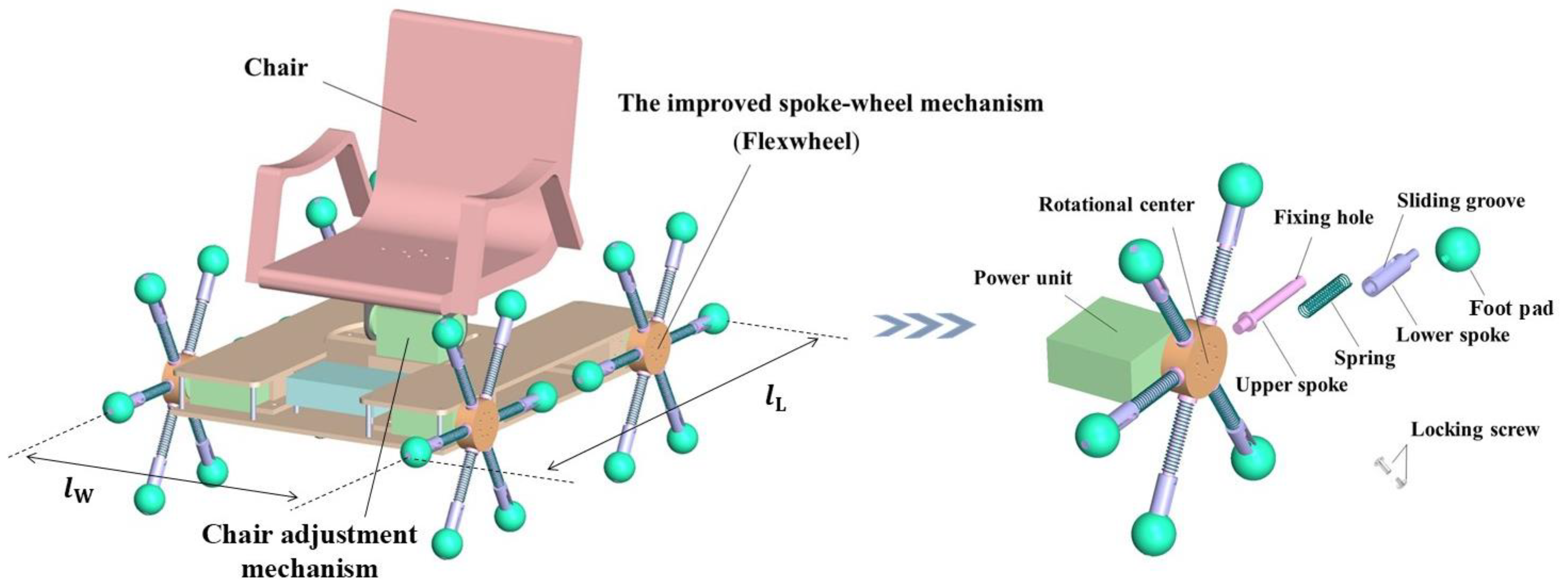
2. Mechanism Design
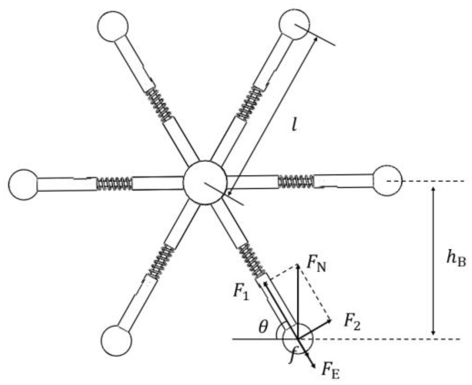
3. Theoretical Analysis
3.1. Spring Configuration
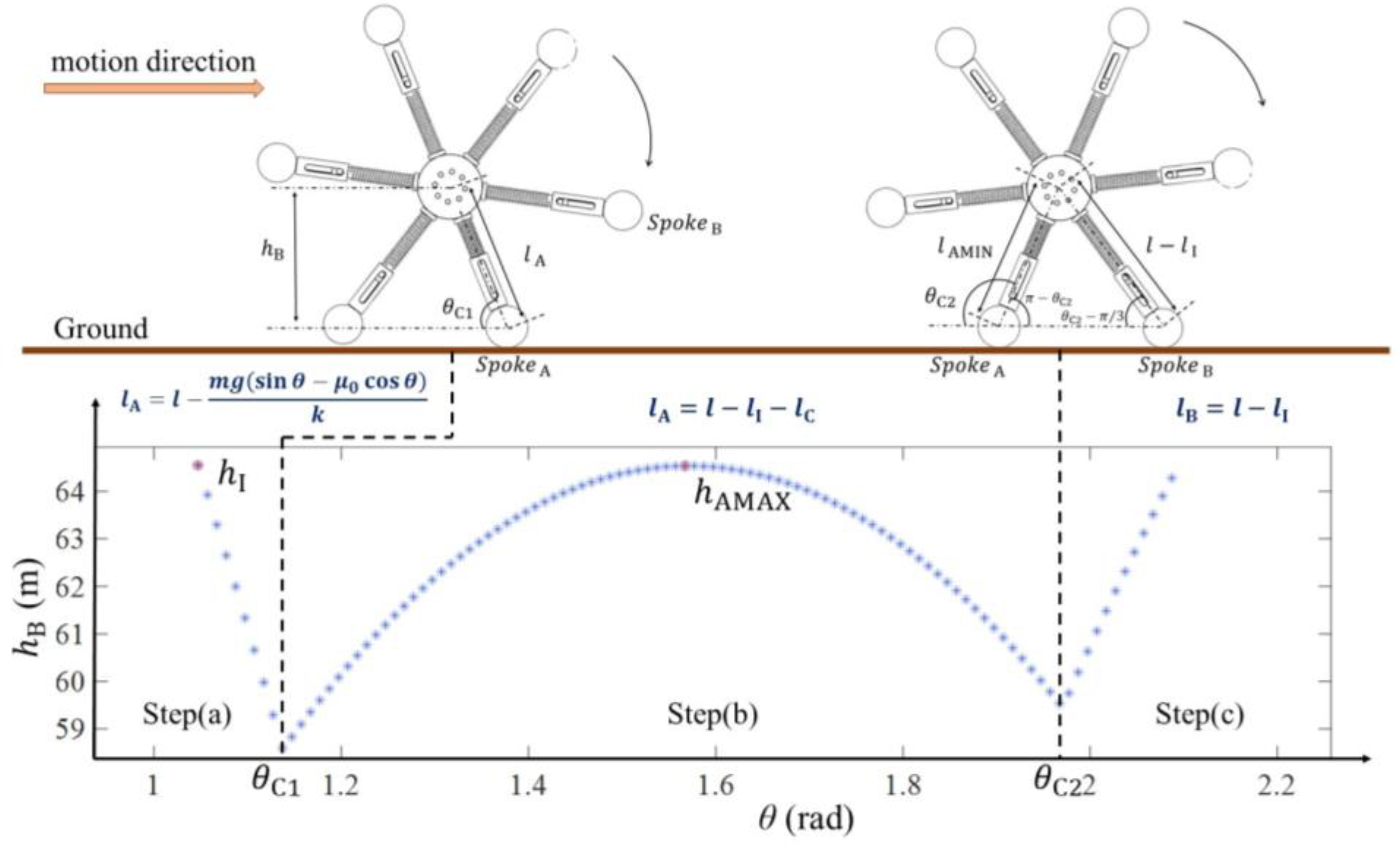
3.1.1. Spoke Deformation Analysis
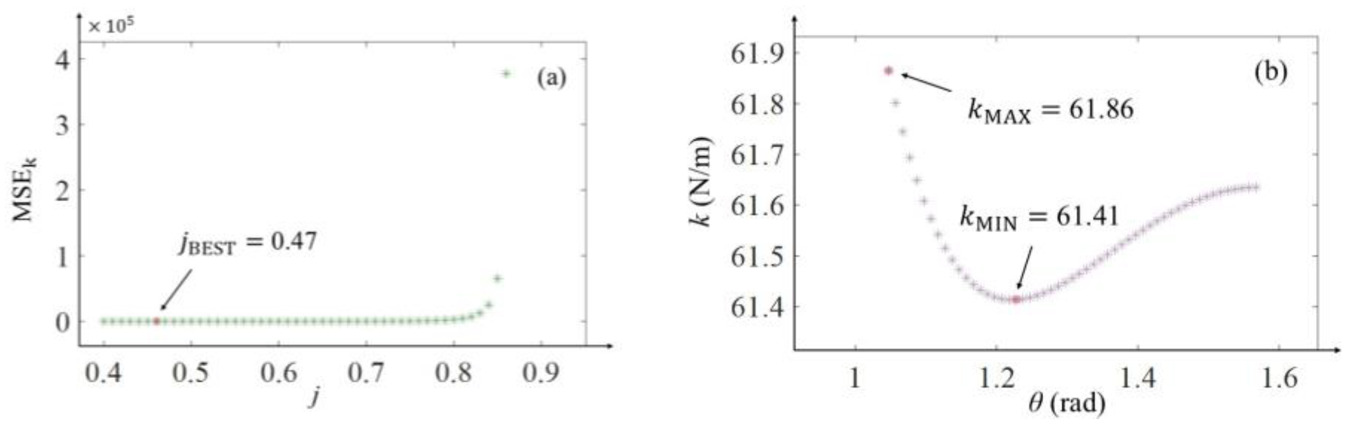
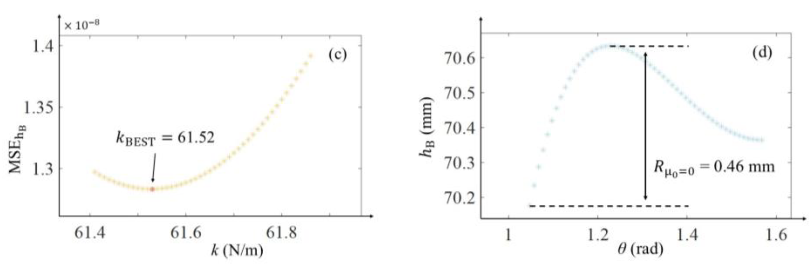
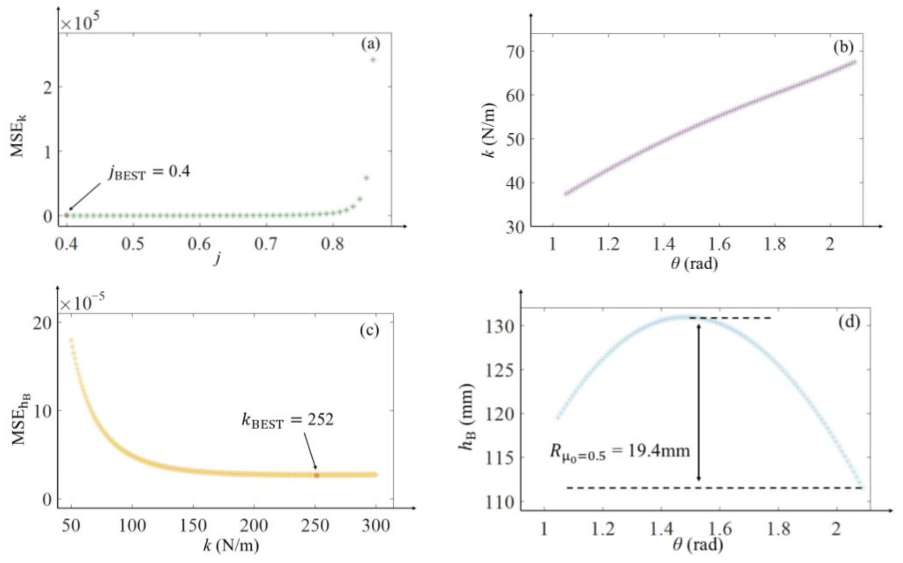
3.1.2. Selection Method for Spring Constant
- 1.
- Determine the optimal body height ratio;
- 2.
- Determine the range of when;
- 3.
- Determine the optimal spring constant;
- 4.
- Determine the range of when;
3.1.3. Pre-Compression Determination
3.2. Theoretical Validation
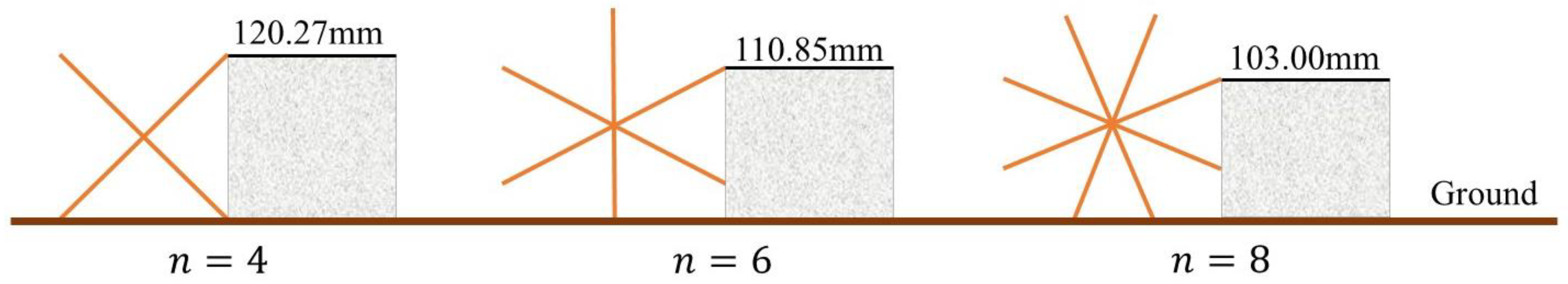
3.3. Maximum Climbing Height
4. Simulation Verification
- 3D Modeling
- 2.
- Simulation Environment Integration
- 3.
- Control Program Development
- 4.
- Physics Engine and Joint Configuration
4.1. Flat Terrain Motion Simulation
4.2. Stair Climbing Simulation
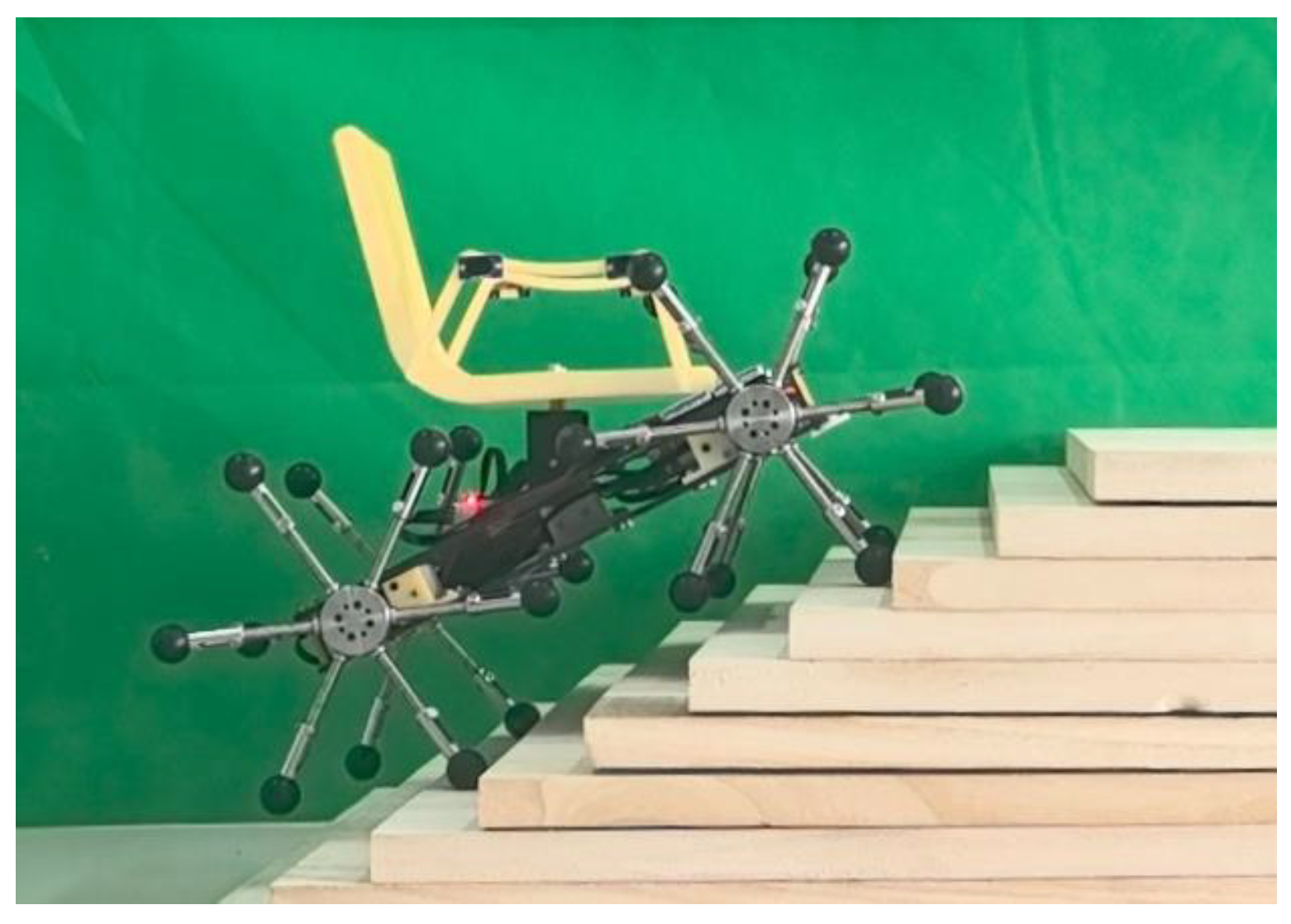
5. Experimental Validation
5.1. Prototype Fabrication
5.2. Flat Terrain Motion Experiment
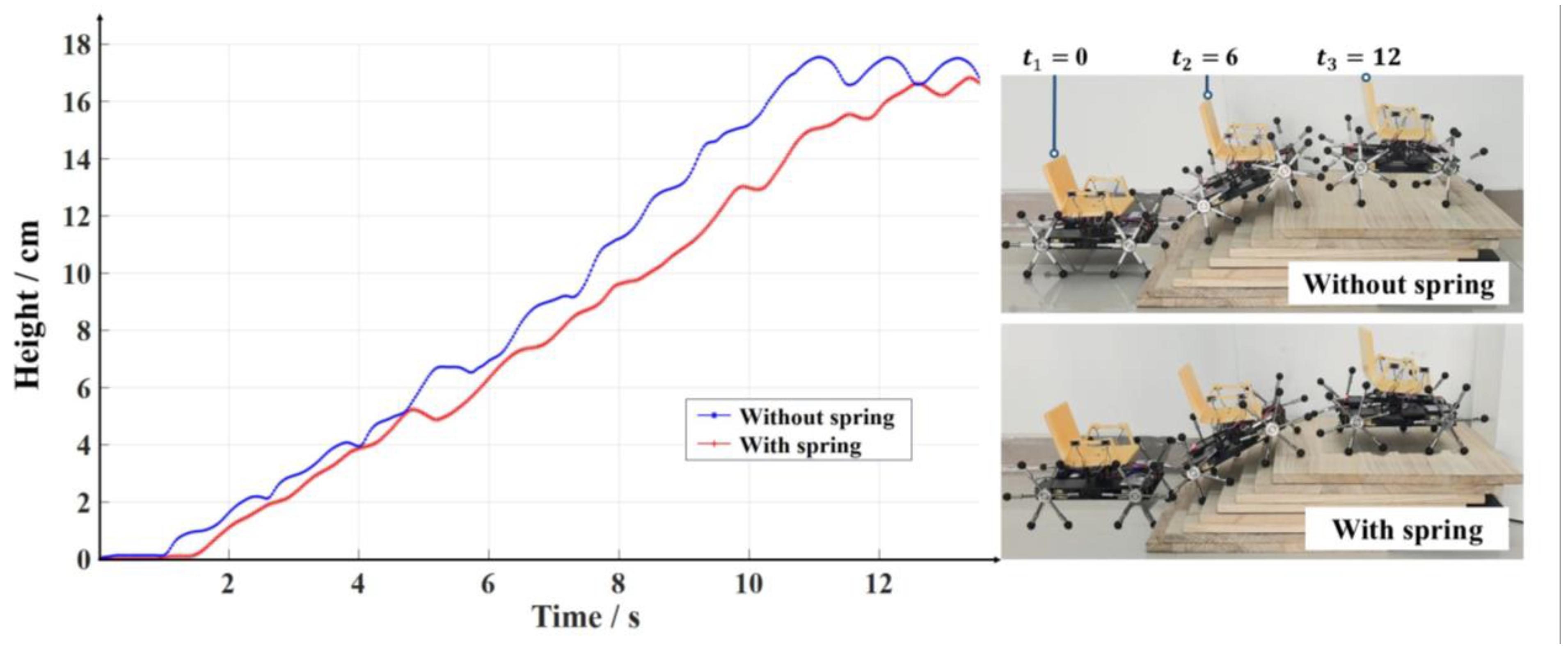
5.3. Stair-Climbing Experiment
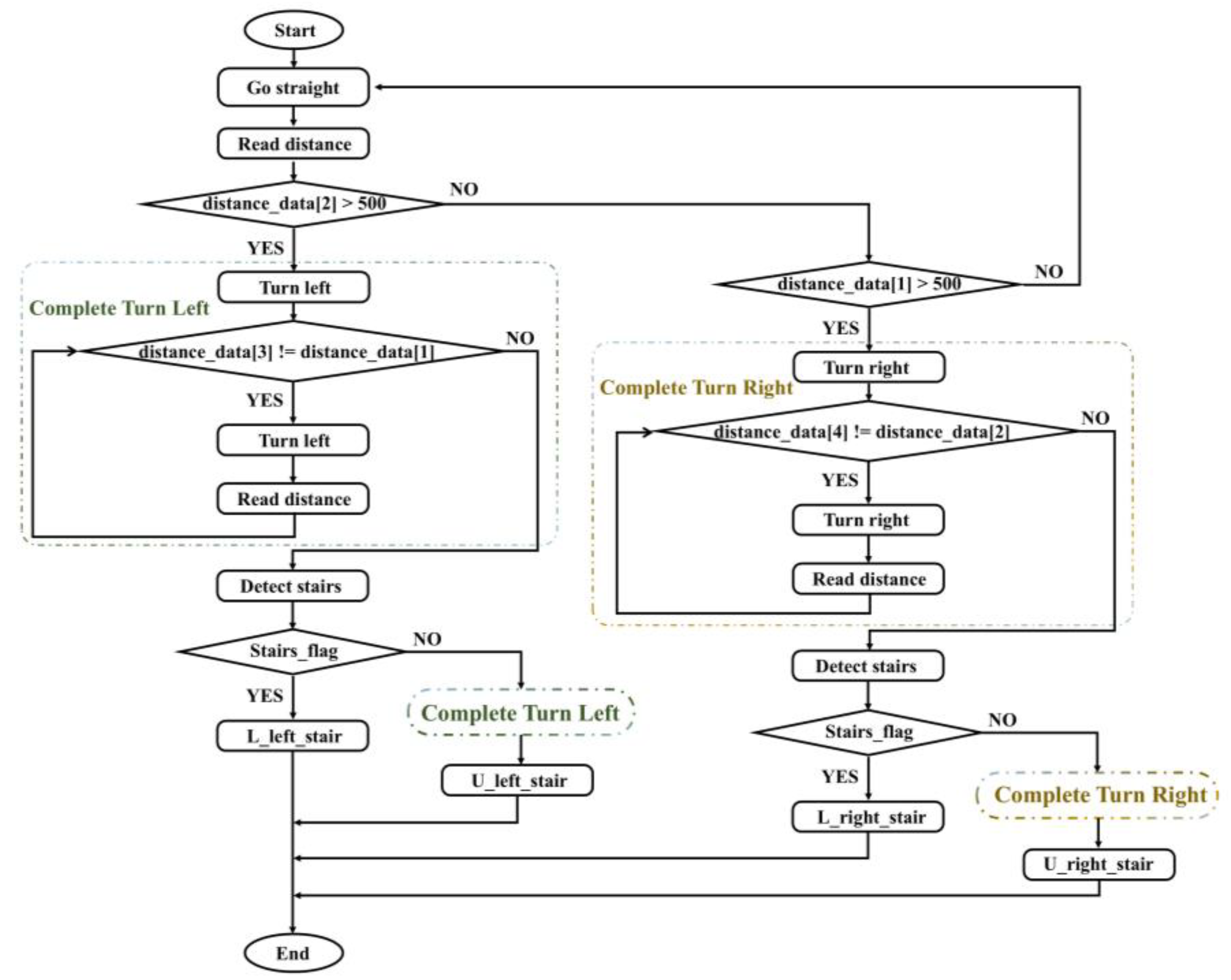
5.4. Multi-Sensor Fusion Stair Climbing Experiment
6. Conclusions
7. Patents
- Patent Number: CN115817066B.
- Applicant: Nanjing University of Information Science and Technology.
- Inventors: Yuting Li, Zhong Wei, Jiwen Zhang. et al.
- Filing Date: 24 November 2022.
- Publication Date: 16 August 2024.
- Status: Granted.
Supplementary Materials
Author Contributions
Funding
Institutional Review Board Statement
Informed Consent Statement
Data Availability Statement
Acknowledgments
Conflicts of Interest
References
- Luoma-Halkola, H.; Häikiö, L. Independent living with mobility restrictions: Older people’s perceptions of their out-of-home mobility. Ageing Soc. 2022, 42, 249–270. [Google Scholar] [CrossRef]
- Sanderson, W.C.; Scherbov, S. A new perspective on population aging. Demogr. Res. 2007, 16, 27–58. [Google Scholar] [CrossRef]
- Wu, Y.; Xiong, Y.; Wang, P.; Liu, R.; Jia, X.; Kong, Y.; Li, F.; Chen, C.; Zhang, X.; Zheng, Y. Risk factors of cardiovascular and cerebrovascular diseases in young and middle-aged adults: A meta-analysis. Medicine 2022, 101, e32082. [Google Scholar] [CrossRef] [PubMed]
- Fang, L.; Lu, T.; He, W.; Yuan, K. Dynamic and Tip-Over Stability Analysis of a Planetary Wheeled Stair-Climbing Wheelchair. In Proceedings of the 2012 IEEE International Conference on Mechatronics and Automation, Chengdu, Sichuan, China, 5–8 August 2012; pp. 2541–2546. [Google Scholar]
- Cooper, R.A.; Boninger, M.L.; Cooper, R.; Kelleher, A. Use of the INDEPENDENCE 3000 IBOT™ transporter at home and in the community: A case report. Disabil. Rehabil. Assist. Technol. 2006, 1, 111–117. [Google Scholar] [CrossRef] [PubMed]
- Guarnieri, M.; Takao, I.; Debenest, P.; Takita, K.; Fukushima, E.; Hirose, S. HELIOS IX Tracked Vehicle for Urban Search and Rescue Operations: Mechanical Design and First Tests. In Proceedings of the 2008 IEEE/RSJ International Conference on Intelligent Robots and Systems, Nice, France, 22–26 September 2008; pp. 1612–1617. [Google Scholar]
- Sugahara, Y.; Ohta, A.; Hashimoto, K.; Sunazuka, H.; Kawase, M.; Tanaka, C.; Lim, H.-o.; Takanishi, A. Walking Up and Down Stairs Carrying a Human By a Biped Locomotor with Parallel Mechanism. In Proceedings of the 2005 IEEE/RSJ International Conference on Intelligent Robots and Systems, Edmonton, AB, Canada, 2–6 August 2005; pp. 1489–1494. [Google Scholar]
- Baishya, N.J.; Bhattacharya, B.; Ogai, H.; Tatsumi, K. Analysis and design of a minimalist step climbing robot. Appl. Sci. 2021, 11, 7044. [Google Scholar] [CrossRef]
- Zhengyan, Q.; Hongbo, W.; Zhen, H. Kinematics of a Quadruped/Biped Reconfigurable Walking Robot with Parallel Leg Mechanisms. In Proceedings of the ASME/IFToMM International Conference on Reconfigurable Mechanisms and Robots, London, UK, 22–24 June 2009; pp. 558–564. [Google Scholar]
- Yu, S.; Wang, T.; Wang, Y.; Zhi, D.; Yao, C.; Li, X.; Wang, Z.; Luo, Y.; Wang, Z. A Tip-Over and Slippage Stability Criterion for Stair-Climbing of a Wheelchair Robot with Variable Geometry Single Tracked Mechanism. In Proceedings of the 2012 IEEE International Conference on Information and Automation, Shenyang, China, 6–8 June 2012; pp. 88–93. [Google Scholar]
- Tao, W.; Jia, Y.; Liu, T.; Yi, J.; Wang, H.; Inoue, Y. A novel wheel-track hybrid electric powered wheelchair for stairs climbing. J. Adv. Mech. Des. Syst. Manuf. 2016, 10, JAMDSM0060. [Google Scholar] [CrossRef]
- Imaoka, N.; Kimura, K.; Noda, S.; Kakiuchi, Y.; Inaba, M.; Ando, T. A Transformable Human-Carrying Wheel–Leg Mobility for Daily Use. In Proceedings of the 2021 IEEE/RSJ International Conference on Intelligent Robots and Systems (IROS), Prague, Czech Republic, 27 September–1 October 2021; pp. 3005–3011. [Google Scholar]
- Lee, J.-Y.; Han, S.; Kim, M.; Seo, Y.-S.; Park, J.; Park, D.I.; Park, C.; Seo, H.; Lee, J.; Kim, H.-S. Variable-stiffness–morphing wheel inspired by the surface tension of a liquid droplet. Sci. Robot. 2024, 9, eadl2067. [Google Scholar] [CrossRef] [PubMed]
- Tao, W.; Xu, J.; Liu, T. Electric-powered wheelchair with stair-climbing ability. Int. J. Adv. Robot. Syst. 2017, 14, 1729881417721436. [Google Scholar] [CrossRef]
- Deng, Y.; Hua, Y.; Napp, N.; Petersen, K. A compiler for scalable construction by the termes robot collective. Robot. Auton. Syst. 2019, 121, 103240. [Google Scholar] [CrossRef]
- Schroer, R.T.; Boggess, M.J.; Bachmann, R.J.; Quinn, R.D.; Ritzmann, R.E. Comparing Cockroach and Whegs Robot Body Motions. In Proceedings of the IEEE International Conference on Robotics and Automation, New Orleans, LA, USA, 26 April–1 May 2004; pp. 3288–3293. [Google Scholar]
- Hidalgo, J. Navigation and Slip Kinematics for High Performance Motion Models. In Proceedings of the Symposium on Advanced Space Technologies in Robotics and Automation, Sydney, Australia, 2–4 December 2013. [Google Scholar]
- Ai, X.; Yue, H.; Wang, W.D. Crawling soft robot exploiting wheel-legs and multimodal locomotion for high terrestrial maneuverability. IEEE Trans. Robot. 2023, 39, 4230–4239. [Google Scholar] [CrossRef]
- Zheng, C.; Sane, S.; Lee, K.; Kalyanram, V.; Lee, K. α-WaLTR: Adaptive Wheel-and-Leg Transformable Robot for Versatile Multiterrain Locomotion. IEEE Trans. Robot. 2022, 39, 941–958. [Google Scholar] [CrossRef]
- Xu, Q.; Xu, H.; Xiong, K.; Zhou, Q.; Guo, W. Design and Analysis of a Bi-Directional Transformable Wheel Robot Trimode. In Proceedings of the 2021 IEEE/RSJ International Conference on Intelligent Robots and Systems (IROS), Prague, Czech Republic, 27 September–1 October 2021; pp. 8396–8403. [Google Scholar]
- Sun, C.; Yang, G.; Yao, S.; Liu, Q.; Wang, J.; Xiao, X. Rhex-t3: A transformable hexapod robot with ladder climbing function. IEEE/ASME Trans. Mechatron. 2023, 28, 1939–1947. [Google Scholar] [CrossRef]
- Yoon, H.; Kim, S.; Park, I.; Heo, J.; Kim, H.S.; Seo, T. 2 DOF transformable wheel design based on geared 8 bar parallel linkage mechanism. Sci. Rep. 2024, 14, 379. [Google Scholar] [CrossRef] [PubMed]
- Murphy, D.; Giuliani, M.; Bremner, P. Evaluation and Design Recommendations for a Folding Morphing-Wheg Robot for Nuclear Characterisation. In Proceedings of the 2024 IEEE/RSJ International Conference on Intelligent Robots and Systems (IROS), Abu Dhabi, United Arab Emirates, 13–18 October 2024; pp. 9088–9093. [Google Scholar]
- Jeans, J.B.; Hong, D. IMPASS: Intelligent Mobility Platform with Active Spoke System. In Proceedings of the 2009 IEEE International Conference on Robotics and Automation, Kobe, Japan, 12–17 May 2009; pp. 1605–1606. [Google Scholar]
- Oh, S.; Kim, H.; Jeon, S.; Shin, B.; Ryu, B.; Kim, Y. Design of a mobile robot with 2-DOF compliant wheel-legs by using a linear spring. Microsyst. Technol. 2023, 29, 1189–1196. [Google Scholar] [CrossRef]
- Gillespie, T. Fundamentals of Vehicle Dynamics; SAE Int.: Warrendale, PA, USA, 2021; pp. 11–12. [Google Scholar]


| Number of Spokes n | The Range of the Body Height | Maximum Climbing Height | |
|---|---|---|---|
| 4 | 56.88 N/m | 2.3 mm | 120.27 mm |
| 6 | 61.52 N/m | 0.5 mm | 110.85 mm |
| 8 | 62.82 N/m | 0.1 mm | 103.00 mm |
| Description | Symbol | Value |
|---|---|---|
| Length | 380 mm | |
| Width | 200 mm | |
| Number of spokes | 6 | |
| Original spoke length | 150 mm | |
| Spring free length | 100 mm | |
| Rigid segment length | 50 mm | |
| Sliding groove length | 10 mm | |
| Body mass | 2 kg |
| Joints | Parameter | Value |
|---|---|---|
| Revolute joints | Speed [rad/s] | 1.2 |
| Prismatic joints | Pos. min [m] | 0.069 |
| Pos. range [m] | 0.010 | |
| Position [m] | 0.069 | |
| Front prismatic joints | Spring constant K [N/m] | 40.5 |
| Spring constant C [N·s/m] | 9.0 | |
| Rear prismatic joints | Spring constant K [N/m] | 61.7 |
| Spring constant C [N·s/m] | 11.1 |
| Motion Mechanism | Stair Specifications | RMS of Z-Axis Acceleration |
|---|---|---|
| Traditional spoke wheels | 2 cm × 4 cm | 0.48 m/s2 |
| Flexwheels | 2 cm × 4 cm | 0.39 m/s2 |
| Traditional spoke wheels | 3 cm × 10 cm | 0.51 m/s2 |
| Flexwheels | 3 cm × 10 cm | 0.42 m/s2 |
| Traditional spoke wheels | 4 cm × 8 cm | 0.52 m/s2 |
| Flexwheels | 4 cm × 8 cm | 0.47 m/s2 |
| Motion Mechanism | Stair Specifications | RMS of Z-Axis Acceleration |
|---|---|---|
| Traditional spoke wheels | 2 cm × 4 cm | 0.45 m/s2 |
| Flexwheels | 2 cm × 4 cm | 0.36 m/s2 |
| Flexwheels | 4 cm × 8 cm | 0.43 m/s2 |
Disclaimer/Publisher’s Note: The statements, opinions and data contained in all publications are solely those of the individual author(s) and contributor(s) and not of MDPI and/or the editor(s). MDPI and/or the editor(s) disclaim responsibility for any injury to people or property resulting from any ideas, methods, instructions or products referred to in the content. |
© 2025 by the authors. Licensee MDPI, Basel, Switzerland. This article is an open access article distributed under the terms and conditions of the Creative Commons Attribution (CC BY) license (https://creativecommons.org/licenses/by/4.0/).
Share and Cite
Li, Y.; Wei, Z.; Guo, J.; Ren, J.; Ding, Y.; Wang, W.; Liu, J.; Song, A. A Stair-Climbing Wheelchair with Novel Spoke Wheels for Smooth Motion. Appl. Sci. 2025, 15, 5433. https://doi.org/10.3390/app15105433
Li Y, Wei Z, Guo J, Ren J, Ding Y, Wang W, Liu J, Song A. A Stair-Climbing Wheelchair with Novel Spoke Wheels for Smooth Motion. Applied Sciences. 2025; 15(10):5433. https://doi.org/10.3390/app15105433
Chicago/Turabian StyleLi, Yuting, Zhong Wei, Jinlin Guo, Jinyao Ren, Yu Ding, Weixi Wang, Jia Liu, and Aiguo Song. 2025. "A Stair-Climbing Wheelchair with Novel Spoke Wheels for Smooth Motion" Applied Sciences 15, no. 10: 5433. https://doi.org/10.3390/app15105433
APA StyleLi, Y., Wei, Z., Guo, J., Ren, J., Ding, Y., Wang, W., Liu, J., & Song, A. (2025). A Stair-Climbing Wheelchair with Novel Spoke Wheels for Smooth Motion. Applied Sciences, 15(10), 5433. https://doi.org/10.3390/app15105433