Article

Dynamic Characterization and Parametric Optimization of Secondary Cushioned Pump Valves in Drilling Systems: A 3D Transient Fluid–Structure Interaction Study

by
Yi Wu
1,2 and
Yongjun Hou
1,*
1
School of Mechanical Engineering, Southwest Petroleum University, Chengdu 610500, China
2
School of Intelligent Manufacturing, Panzhihua University, Chengdu 617000, China
*
Author to whom correspondence should be addressed.
Appl. Sci. 2025, 15(10), 5431; https://doi.org/10.3390/app15105431
Submission received: 12 April 2025 / Revised: 8 May 2025 / Accepted: 10 May 2025 / Published: 13 May 2025

Abstract

:
The dynamic response of pump valve motion directly influences the volumetric efficiency of drilling pumps and serves as a critical factor in performance enhancement. This study presents a coupled fluid–structure interaction (FSI) analysis of a novel secondary cushioned pump valve for drilling systems. A validated 3D transient numerical model, integrating piston–valve kinematic coupling and clearance threshold modeling, was developed to resolve the dynamic interactions between reciprocating mechanisms and turbulent flow fields. The methodology addresses critical limitations in conventional valve closure simulations by incorporating a geometrically adaptive mesh refinement strategy while maintaining computational stability. Transient velocity profiles confirm complete sealing integrity with near-zero leakage (<0.01 m/s), while a 39.3 MPa inter-pipeline pressure differential induces 16% higher jet velocities in suction valves compared to discharge counterparts. The secondary cushioned valve design reduces closure hysteresis by 22%, enhancing volumetric efficiency under rated conditions. Parametric studies reveal structural dominance, with increases in cylindrical spring stiffness lowering discharge valve lift by 7.2% and velocity amplitude by 2.74%, while wave spring optimization (24% stiffness enhancement) eliminates pressure decay and reduces perturbations by 90%. Operational sensitivity analysis demonstrates stroke frequency as a critical failure determinant: elevating speed from 90 to 120 rpm amplifies suction valve peak velocity by 59.87% and initial closing shock by 129.07%. Transient flow simulations validate configuration-dependent performance, showing 6.3 ± 0.1% flow rate deviations from theoretical predictions (Qt_max = 40.0316 kg/s) due to kinematic hysteresis. This study establishes spring parameter modulation as a key strategy for balancing flow stability and mitigating cushioning-induced oscillations. These findings provide actionable insights for optimizing high-pressure pump systems through hysteresis control and parametric adaptation.

1. Introduction

The drilling pump, a widely utilized positive displacement reciprocating pump in the petroleum industry, represents one of the most critical components of drilling operations. The efficiency and reliability of drilling pumps serve as vital guarantees for drilling operations. The motion hysteresis of pump valves exerts significant impacts on pump performance, while simultaneously causing valve failures due to impulsive loading. With rapid advancements in drilling technologies, the requirement for enhanced discharge pressure and flow capacity has intensified. Although increasing stroke frequency and stroke length are effective approaches to enhancing displacement and efficiency, such intensification accelerates valve failure mechanisms [1,2]. This technical contradiction necessitates urgent solutions for enhancing pumping efficiency while extending valve service life.
The dynamic behavior of pump valves constitutes a critical factor influencing both drilling pump performance and valve failure mechanisms. Previous investigations have extensively investigated pump performance and valve dynamics, encompassing valve motion analysis, experimental measurements, flow field characteristics within pump chambers, and valve impact dynamics [3,4,5,6,7,8,9]. Owing to the geometric complexity of the pump’s hydraulic end, and the coupled motion between pistons and valves, establishing precise mathematical models for valve dynamics presents significant challenges [7,8,9]. Bench testing, combined with numerical simulations, enables more accurate determination of valve motion characteristics [10,11,12,13,14,15,16,17]. Particularly during new product development phases, numerical methods serve as cost-effective approaches to rapid prototype performance evaluation, effectively reducing development costs and cycle times.
The authors’ investigation reveals that current research on drilling pump performance inadequately addresses the kinematic coupling characteristics among pistons, suction valves, and discharge valves [18,19,20,21,22,23]. Prevailing methodologies predominantly employ separate modeling approaches for suction and discharge stroke valve dynamics. Notable works by investigators employed dynamic mesh techniques with user-defined functions (UDFs) to elucidate fluid–valve interactions, demonstrating that high-velocity erosion in valve gaps and valve disc–seat impacts constitute primary failure mechanisms. Complementary research by G. Zhu et al. [24] applied computational fluid dynamics (CFD) to analyze cavitation and vapor bubble formation in reciprocating pump valves with variable-stiffness springs during suction strokes, establishing critical patterns for cavitation prevention. However, these studies predominantly focused on isolated valve dynamics while neglecting system-level interactions with adjacent components, deviating from actual operational conditions. A notable advancement by Alberto Menéndez-Blanco et al. [25] developed a comprehensive three-dimensional unsteady model for diaphragm pumps, correlating check valve responses with operational parameters to inform maintenance strategies. Common to these computational frameworks is the preservation of microscale clearance between valve seats and discs to satisfy structural topology requirements for CFD analysis. This modeling convention introduces discrepancies in initial valve configurations compared to physical systems, potentially compromising analytical accuracy through boundary condition artifacts.
This study develops a validated three-dimensional unsteady model of drilling pumps, incorporating a novel secondary cushioning mechanism for pump valves. The model implements the kinematic coupling analysis of pistons, suction valves, and discharge valves through a clearance-based modeling framework that eliminates computational errors inherent in conventional valve gap preservation approaches. Comprehensive transient simulations under varied operational conditions reveal the performance enhancement mechanisms of the optimized pump configuration and characterize the dynamic response of the cushioning system. These findings provide critical references for hydraulic performance optimization and the structural refinement of drilling pump systems.

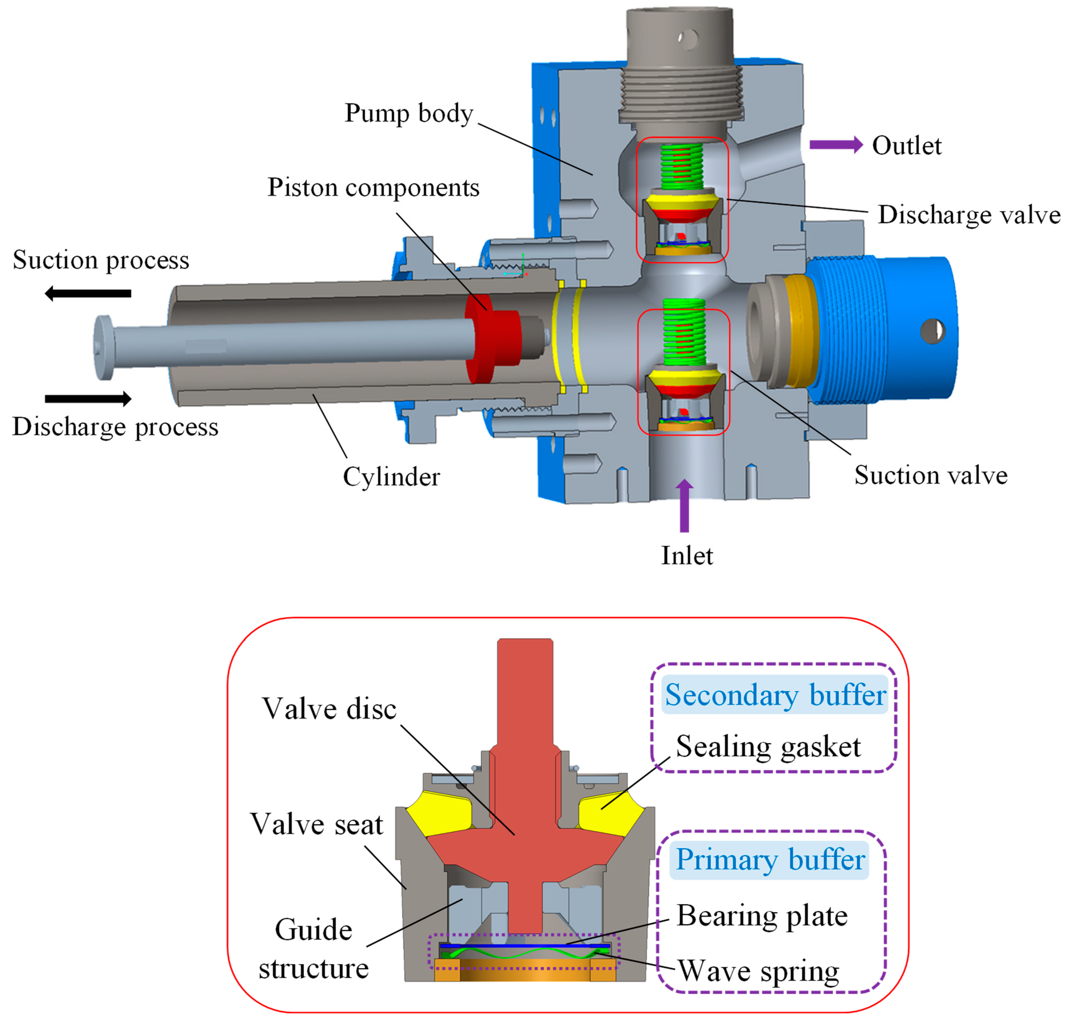
2. Basic Dimensions of Drilling Pump

The hydraulic end configuration of the drilling pump incorporates the following essential components: pistons, pump valves, liner assemblies, suction/discharge manifolds, hydraulic accumulators, and pressure relief valves. To enable computational modeling, auxiliary components are strategically omitted, while preserving the functional core components. As schematically presented in Figure 1, the numerical framework focuses on critical simulation domains and an innovative dual-function pump valve with a secondary damping mechanism. Corresponding dimensional specifications are systematically cataloged in Table 1.
The three-dimensional computational fluid dynamics (CFD) domain, encompassing internal flow channels and cavities, is constructed in full compliance with moving mesh requirements while maintaining topological consistency, as shown in Figure 2 (left). Mesh generation employs unstructured tetrahedral elements with progressive grid adaptation (minimum cell size Δxmin = 0.27 mm, growth rate 1.15) along valve disc trajectories, enabling the resolution of transient flow characteristics. As shown in Figure 2 (right), the final grid configuration achieves the quality metrics required for the computation, as follows: average skewness < 0.85, orthogonal quality > 0.35, aspect ratio < 3.15.

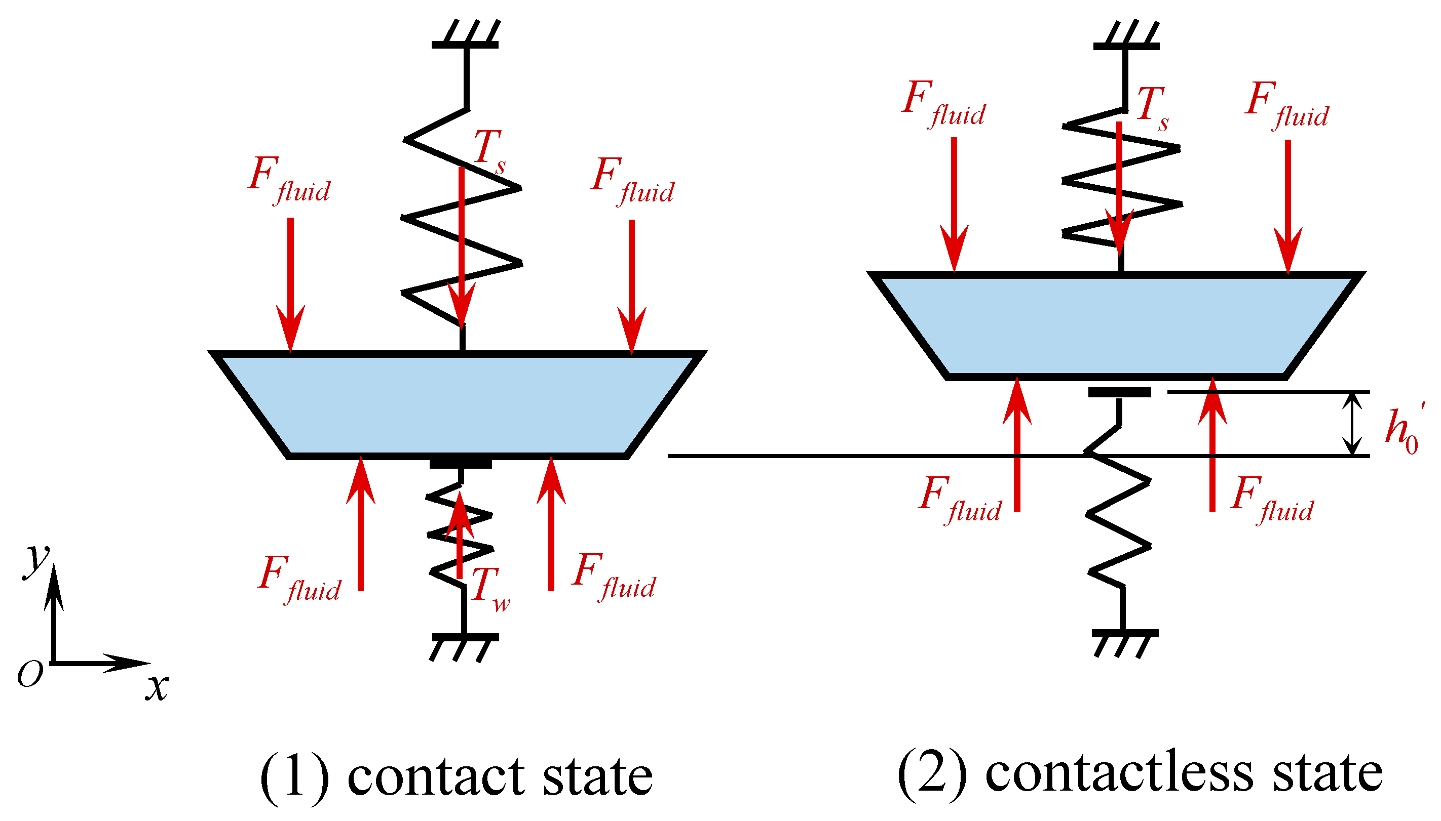
3. Mathematical Model of the Valve Disc Motion

The drilling pump operates through the reciprocating motion of pistons, which cyclically alter the pump chamber volume. This volumetric modulation induces systematic pressure fluctuations that drive the sequential operation of suction and discharge valves to enable mud circulation. The governing mechanism involves valve disc displacement, controlled by dynamic force equilibrium among the pressure differential across the valve disc, gravitational force, resistance from the cylindrical springs, and the preload exerted by wave springs [10,11,13].
Valve actuation follows a force-dependent regime: opening initiates when the resultant pressure differential force surpasses the cumulative resisting forces, while closure commences under force inversion conditions. The force transmission dynamics are principally dictated by the interfacial contact mechanics between the disc guidance assembly and the impact-bearing plate, as schematically depicted in Figure 3. The spring force is modeled as a linear function of displacement based on Hooke’s law, assuming small deformations and isotropic material properties. Frictional damping effects between the spring coils are neglected. The kinematic behavior of the valve disc can be mathematically described by the following second-order differential equation:
m d 2 h d t 2 = P T m g
where m is the mass of the valve disc, kg; h is the lift of the valve disc, m; P is the differential pressure force on the surface of the valve disc, N; T is the spring force on the valve disc, N; and g is the acceleration of gravity, m/s2.
Based on the operational principle of the secondary cushioned pump valve, the spring force acting on the valve disc is formulated as follows:
T = T s T w = k 1 h + h 0 k 2 h 0 h 0 h h 0 T s = k 1 h + h 0 h 0 < h h max
where T s is the spring force of the cylindrical spring, N; T w is the spring force of the wave spring, N; k 1 is the stiffness of the cylindrical spring, N/m; k 2 is the stiffness of wave spring, N/m; h 0 is the pre-compression of the cylindrical spring, m; h 0 is the pre-compression of the wave spring, m; h is the lift of the valve disc, m; and h max is the maximum lift of the valve disc, m.
Substituting Equation (2) into Equation (1), the motion differential equation of the valve disc can be written as follows:
d 2 h d t 2 = P m g k 2 h 0 h k 1 h + h 0 / m 0 h h 0 d 2 h d t 2 = P m g k 1 h + h 0 / m h 0 < h h max
The velocity of the valve disc can be expressed as the following:
v t + Δ t = 0 h t 0 , v t < 0 0 h t 0 , v t 0 , F t o t a l 0 v t + a t Δ t 0 < h t h 0 v t + a t Δ t h 0 < h t < h max 0 h t 0 , v t > 0 0 h t 0 , v t 0 , F t o t a l 0
where a t is the motion acceleration of the valve disc at the current time, m/s2; F t o t a l is the force of the valve disc, N; v t is the velocity of the valve disc at the current time, m/s; v t + Δ t is the velocity of the valve disc at the next time step, m/s; h t is the lift of the valve disc at the current time, m; and Δ t is the time increment, s.
The displacement of the valve disc at the next time step can be expressed as follows:
h t + Δ t = h t + v t Δ t
where h t + Δ t is the lift of the valve disc at the next time, m.
A customized user-defined function (UDF) implemented in C programming language governs the numerical solutions of Equations (3) and (4) to simulate the valve disc’s six-degree-of-freedom (6-DOF) motion. The moving fluid–structure interface is dynamically resolved through a layering/remeshing hybrid algorithm, with mesh topology adaptation controlled by critical displacement thresholds.

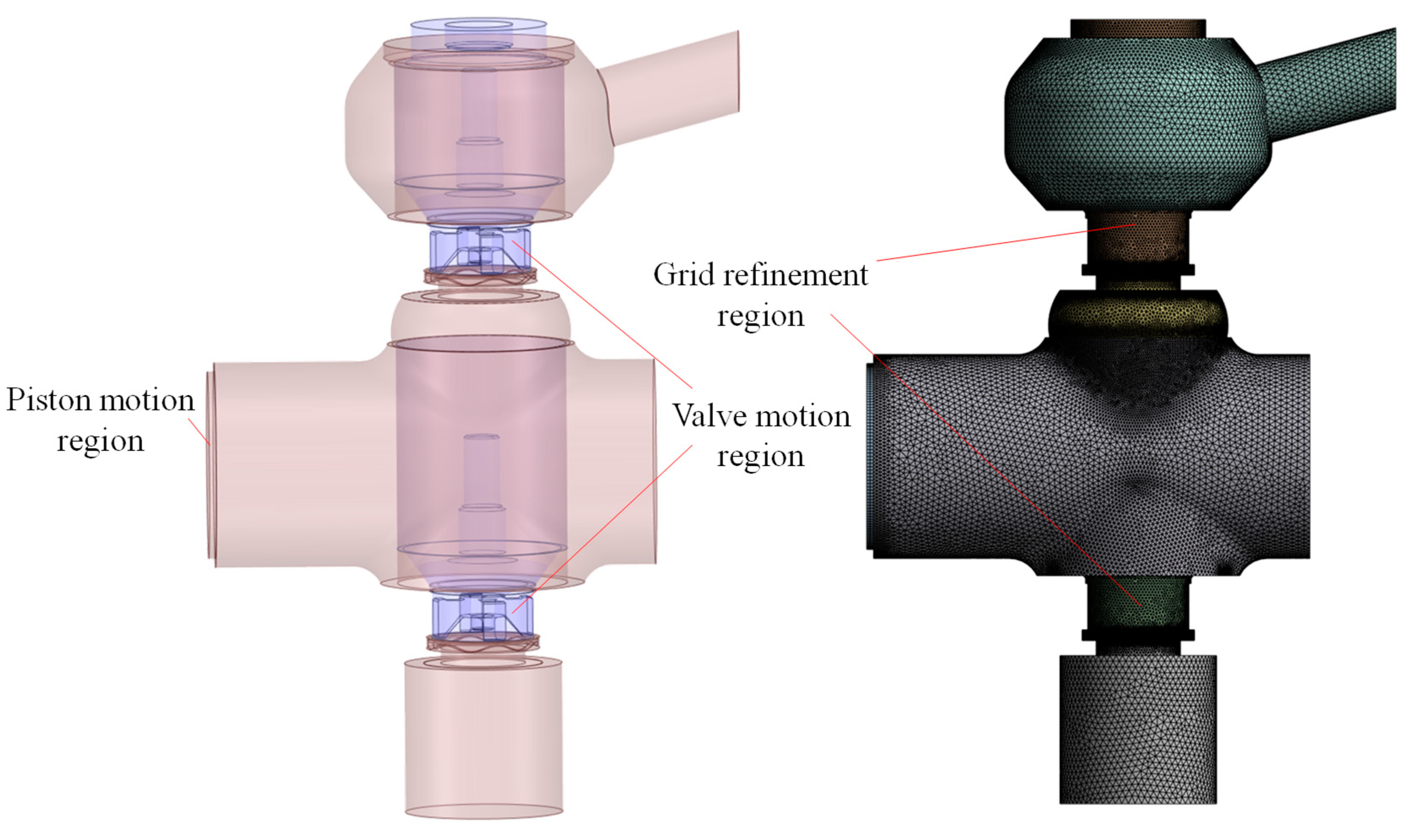
4. Numerical Model and Simulation

The coupled reciprocating kinematics of pistons and valve discs generate intrinsically transient flow patterns within drilling pump chambers. To achieve computationally efficient resolution of turbulence characteristics across operational cycles, the RNG k-ε turbulence model with scalable wall functions was employed [1,2,3,4]. Pressure–velocity coupling is addressed via the PISO algorithm with 20 correction iterations per time step (Δt = 1 × 10⁻⁴ s). A physics-based clearance threshold model is developed to simulate mechanical valve closure events, wherein seat–disc gaps < 0.5 mm are treated as zero-flux boundaries through dynamic porosity modification.
Based on the actual operating conditions of the drilling pump, the boundary conditions are prescribed as follows: the inlet pressure is set to 0.1 MPa and the outlet pressure to 39.3 MPa. The piston kinematics are governed by the pump’s performance envelope (Q = 37.58 L/s) and structural constraints (stroke length = 356 mm), as mathematically defined in Equation (6). This velocity profile is dynamically enforced through a compiled UDF at the moving boundary.
v p = r ω sin ω t + 0.5 λ sin 2 ω t
where v p is the velocity of the piston, m/s; λ is the crank-connecting rod ratio, λ = r / l ; r is the crank radius, m; l is the length of the connecting rod, m; ω is the crank angular velocity, ω = π n / 30 , rad/s; and t is the time of crank rotation, s.
A three-tiered mesh independence study was performed using transient discharge valve kinematics and chamber pressure pulsations as convergence criteria, as quantified in Figure 4. Grid-induced numerical discrepancies exhibited less than 3.8% relative error when the valve region cell size was reduced below 3 mm. The final computational domain contained 6,205,198 tetrahedral elements. An adaptive time-stepping scheme was systematically calibrated to maintain dynamic mesh fidelity during valve disc displacements, yielding an optimized time step of Δt = 5 × 10⁻⁵ s.

5. Results

5.1. Coupled Flow–Valve Dynamics

5.1.1. Sealing Integrity

The integrated kinematic fluid dynamic analysis delineated flow characteristic during a complete operational cycle (T = 0.5714 s). Transient velocity distribution contours (Figure 5) exhibited near-zero magnitudes in discharge valve clearance regions (<0.01 m/s) throughout the suction phase, confirming complete sealing integrity with no detectable fluid bypass. Symmetrical flow suppression occurred in suction valve regions during discharge operations, further corroborating the clearance model’s ability to emulate physical valve closure mechanisms.

5.1.2. Jet-Driven Valve Motion

Notably, the chamber interior maintained quiescent flow states with abrupt velocity transitions confined to valve proximity zones (velocity gradient > 600 s−1). Valve actuation triggered instantaneous jet formation (>12 m/s peak velocity), creating transient pressure differentials (Δp > 0.3 MPa) on valve discs that generated self-sustaining opening forces. Leftward jet deflection during suction strokes (displacement ≈ 3.2 mm) was quantitatively linked to piston-induced fluid inertia through momentum conservation analysis. Comparative velocity profiles at phase-critical instants (t = 1/4 T vs. t = 3/4 T; t = 3/8 T vs. t = 7/8 T) demonstrated greater flow homogeneity during discharge phases, accompanied by suppressed recirculation intensity.

5.1.3. Pressure Differential Effects on Closure Hysteresis

The system’s 39.3 MPa inter-pipeline pressure differential drove suction valve jet velocities exceeding those of the discharge valve by 16%. Kinematic tracking at stroke termini revealed a 22% reduction in suction valve closure hysteresis relative to discharge valves (0.5 T vs. T delay), with the secondary cushioned valve design effectively mitigating delayed closing lag, thereby enhancing volumetric efficiency under rated operating conditions.

5.2. The Motion Characteristics of Pump Valves

The dynamic responses of pump valves are predominantly governed by structural parameters. Four parametric configurations were investigated, as shown in Table 2. To systematically evaluate the parametric sensitivity of pump valve dynamics, four representative operating conditions were investigated with stroke frequencies of 90 rpm, 100 rpm, 105 rpm, and 120 rpm.

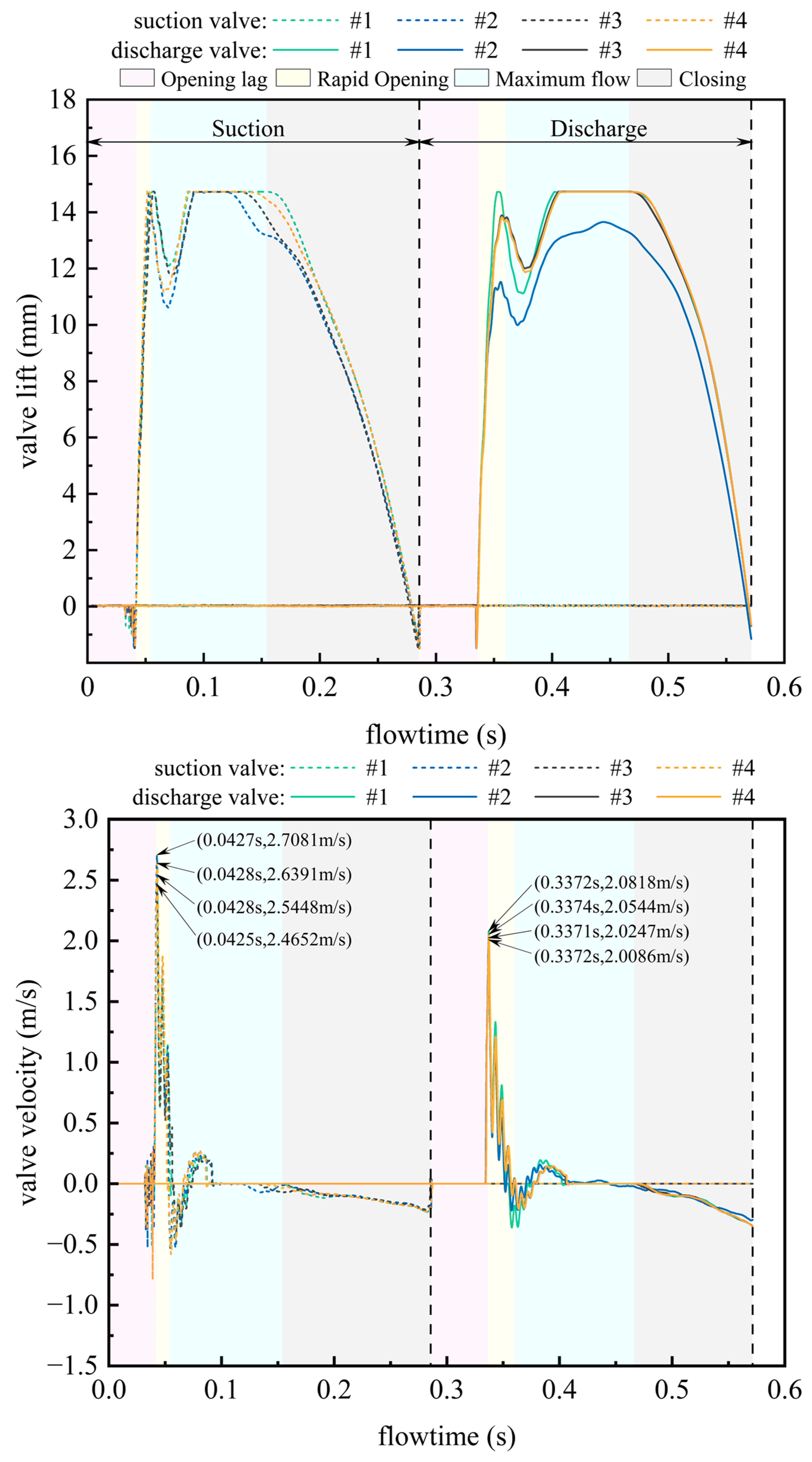
5.2.1. Dynamic Response Characteristics of Valve Operation

Figure 6 delineates the temporal evolution of valve lift and velocity profiles under structural parameters. Both suction and discharge valves demonstrated instantaneous opening responses, marked by characteristic velocity spikes (peak magnitudes > 2.0 m/s) indicative of jump phenomena. Suction valves exhibited 30.08% higher mean maximum velocities compared to discharge valves. Discharge valves displayed 53.78% greater closure hysteresis relative to their suction counterparts during pressure equilibration phases.

5.2.2. Structural Parametric Sensitivity Analysis

Parametric studies identified critical mechanical influences. Increasing cylindrical helical spring stiffness reduced discharge valve maximum lift by 7.2% (ΔL = 1.06 mm) and velocity amplitude by 2.74% (Δv = 0.057 m/s). Elevating spring preload diminished valve lift amplitude marginally (0.02% reduction per 10 N preload increment) while improving positional stability. Structural parameters exerted 2.2-fold greater influence on valve closing dynamics than opening characteristics.

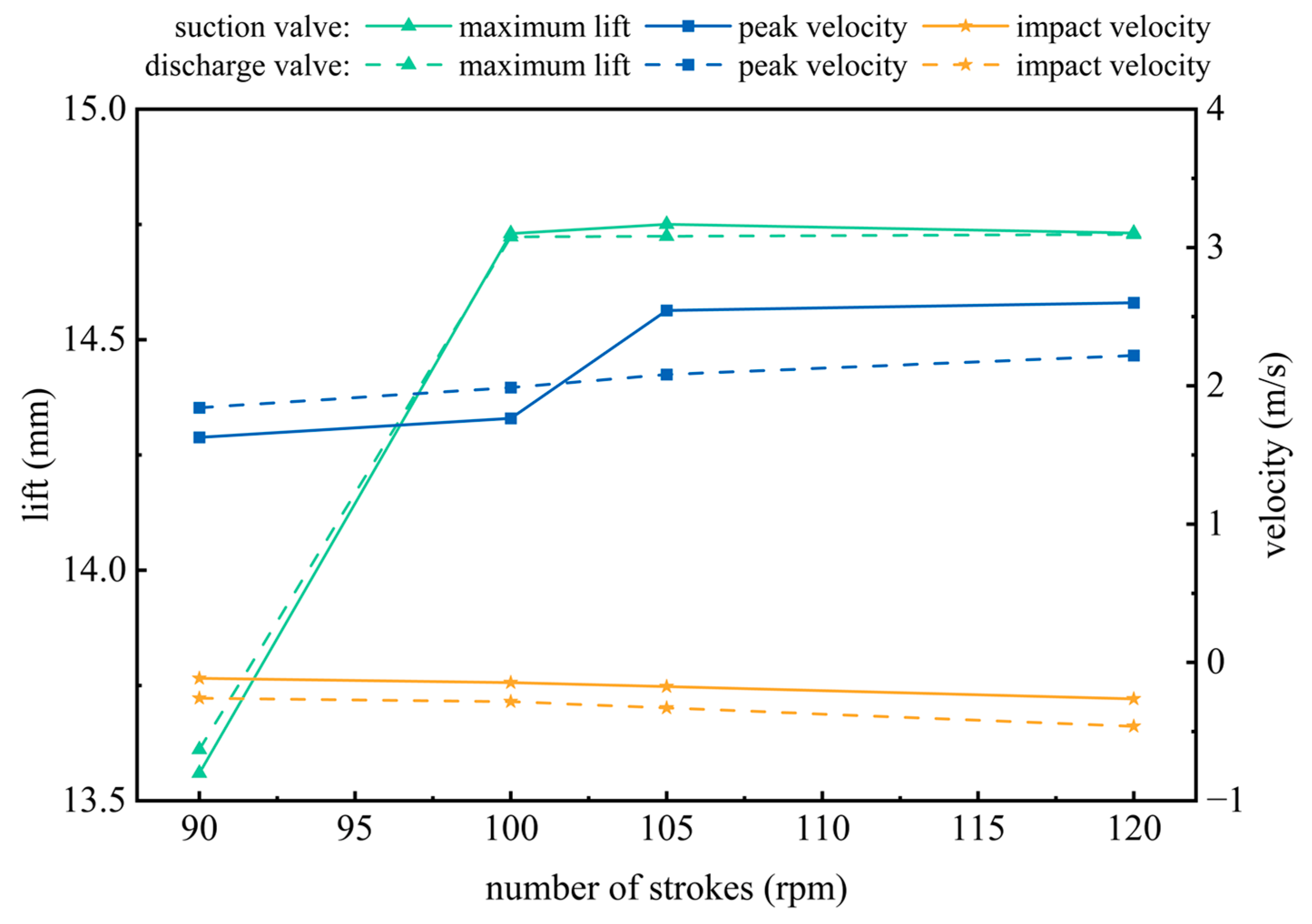
5.2.3. Operating Condition Sensitivity Analysis

Comparative analysis of valve kinematics across operational regimes establishes critical criteria for drilling pump parameter selection (as show in Figure 7). Quantitative measurements reveal that elevating the operational speed from 90 to 120 rpm induces the following results: the maximum lift of the pump valve increases >8%; the peak velocity of the suction valve increases by 59.87%; the initial closing shock velocity increases by 129.07%; the peak velocity of the discharge valve increases by 20.54%; and the initial closing shock velocity increases by 78.97%. This acceleration-proportional intensification corroborates the pump valve failure mechanism proposed in [1,2], demonstrating stroke frequency as a dominant factor governing valve failure.

5.3. Comparative Performance Analysis

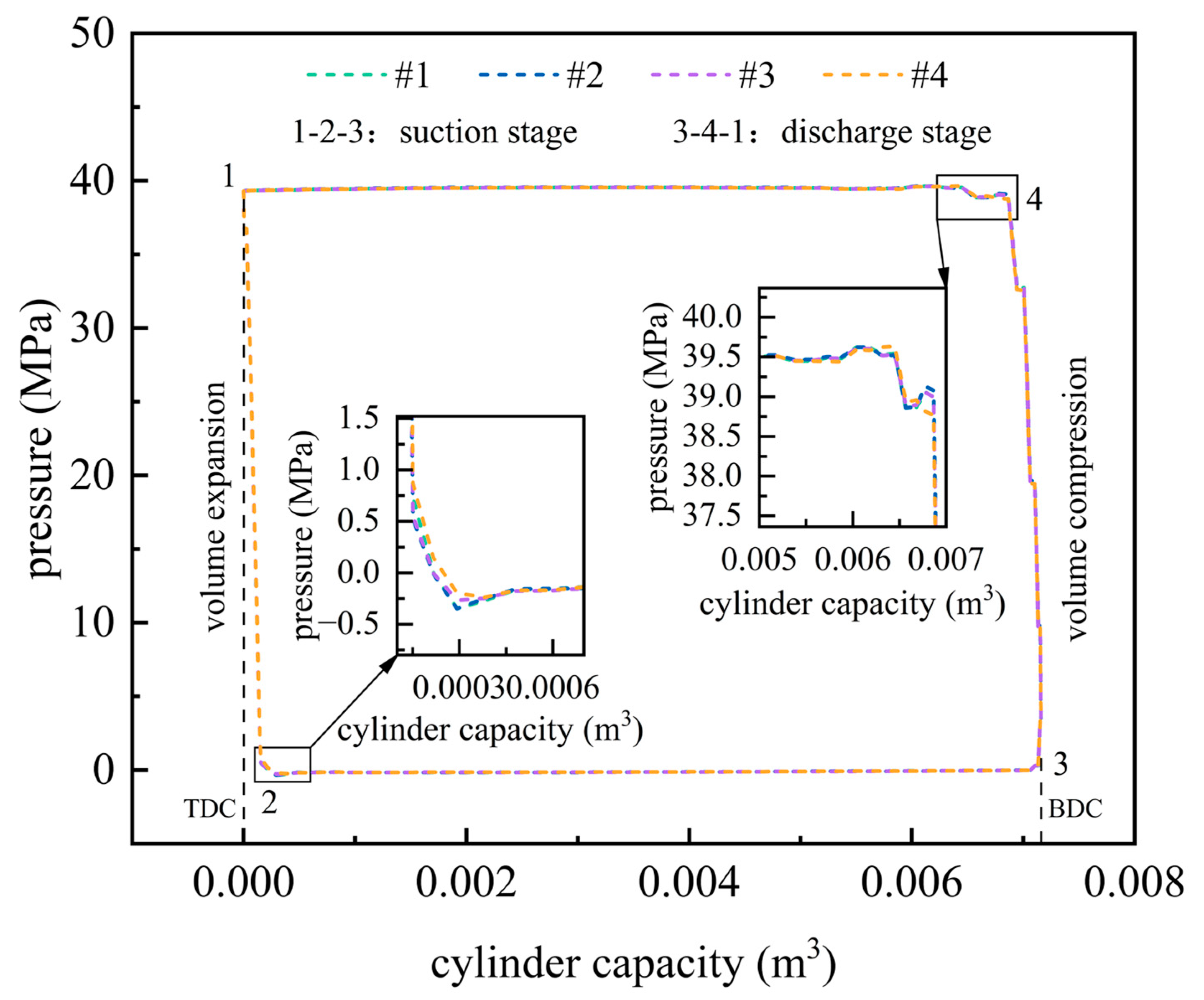
5.3.1. Dynamic P-V Characteristics Across Operational Phases

The pressure–volume diagnostic framework revealed phase-synchronized cyclic behavior across all parametric configurations (Figure 8), with full circulation area maintenance confirming operational integrity. Key transitional features include expansion (1–2) and compression phases (3–4), correlating with liquid compressibility modulus and cylinder wall elasticity. Transient pressure analysis at stroke initiation phases reveals four characteristic pressure states: Point 1: P = 39.298 MPa; Point 2: P = −0.348 MPa; Point 3: P = −0.018 MPa; and Point 4: P = 38.765 MPa. These measurements exhibit strong concordance with established pressure transient profiles [23], while demonstrating significant reductions in pressure fluctuation compared to conventional valve systems. The damped pressure response confirms that the secondary cushion mechanism effectively mitigates valve motion hysteresis.

5.3.2. Parametric Modulation of Pressure Stability

Comparative analysis of wave spring configurations yielded critical performance metrics. Configurations 1-3 exhibited more than 0.7% pressure decay at discharge initiation (Point 4), correlating with valve opening oscillation. Configuration 4 (24% wave spring stiffness enhancement) eliminated pressure decay through optimized damping. Spring parameter optimization reduced pressure perturbation intensity by 90% during valve transitions. Localized trajectory analysis (Points 2 and 4, magnified insets) demonstrate that wave spring optimization effectively reduces opening delay while maintaining volumetric efficiency.

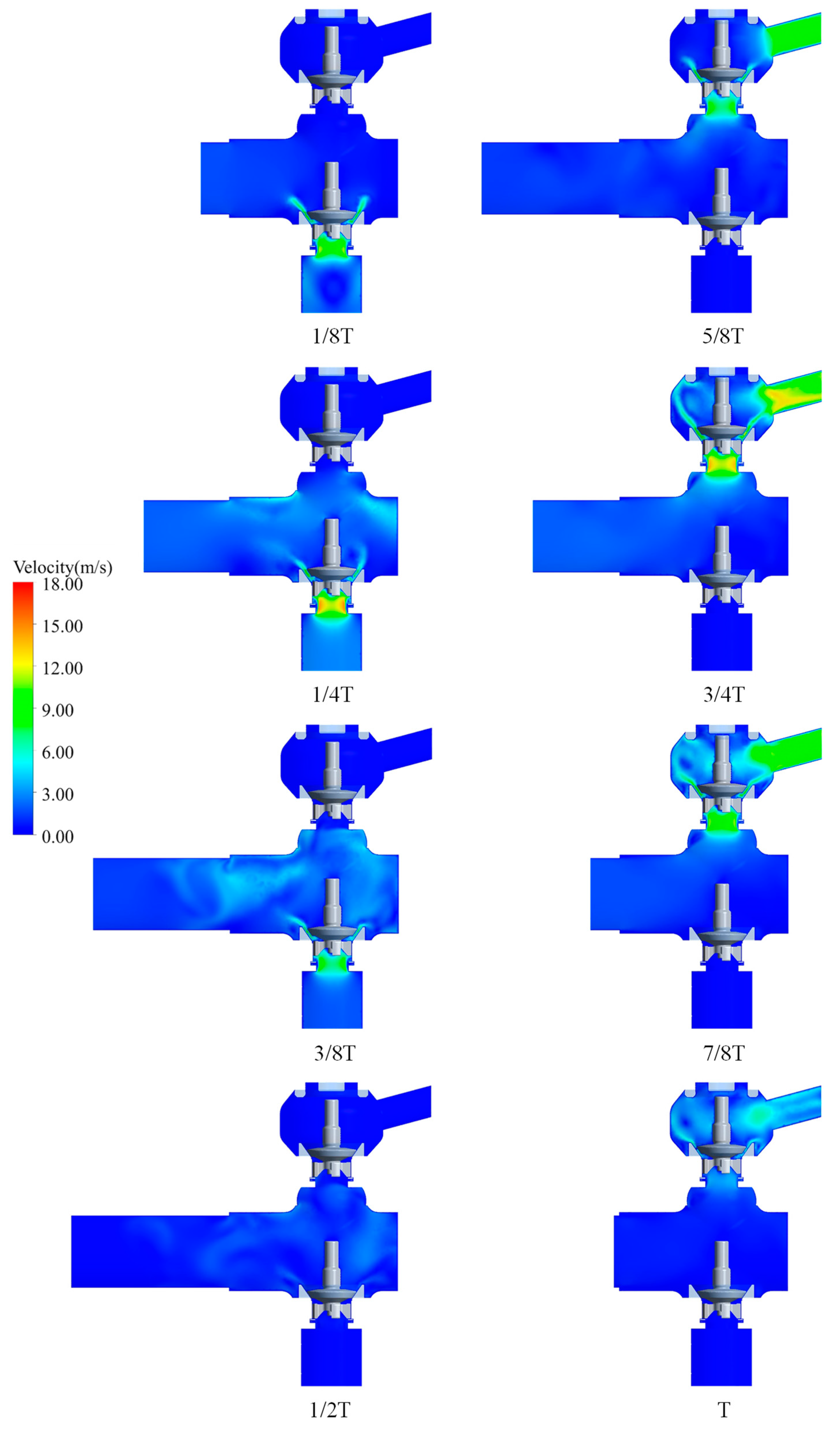
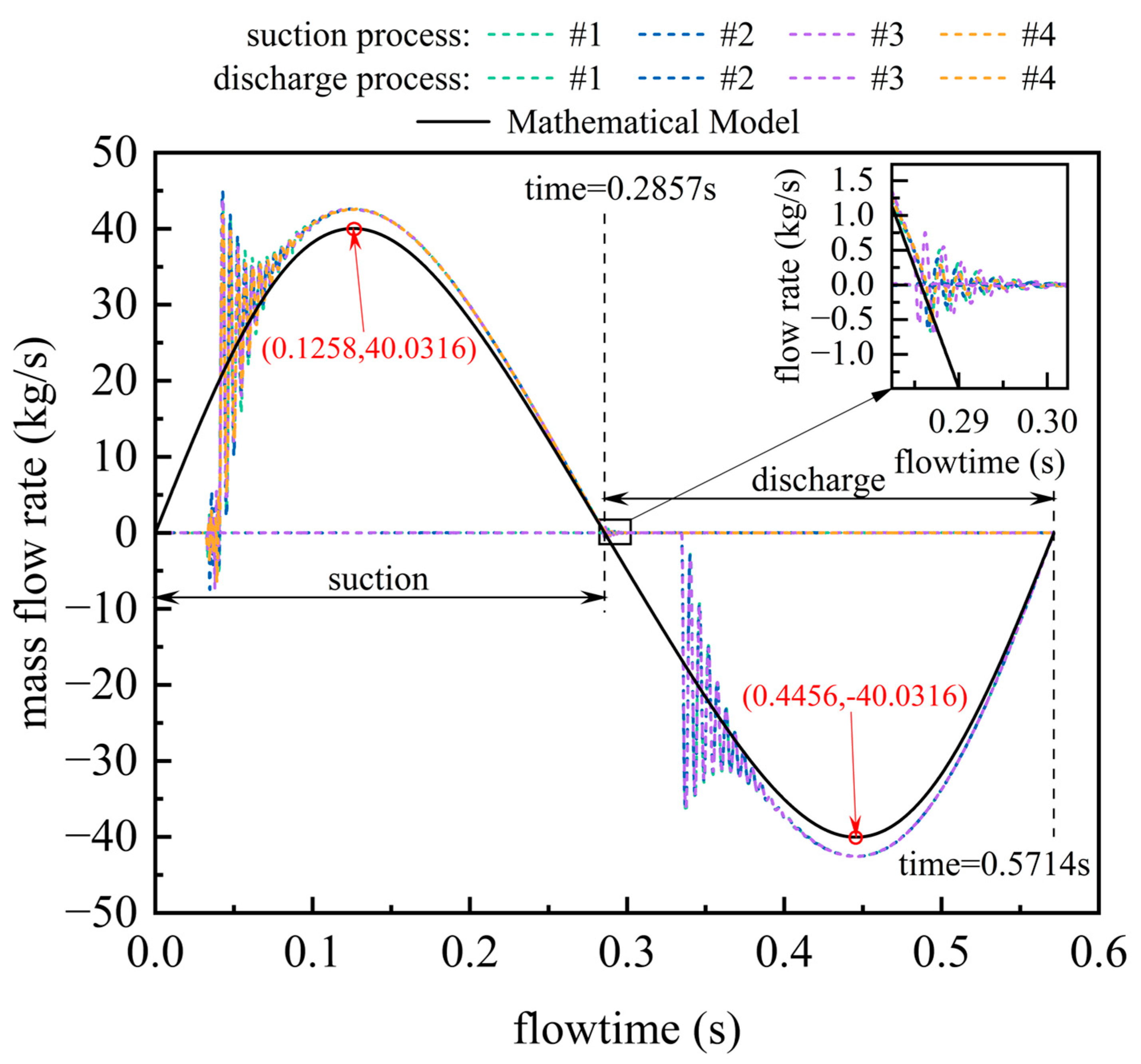
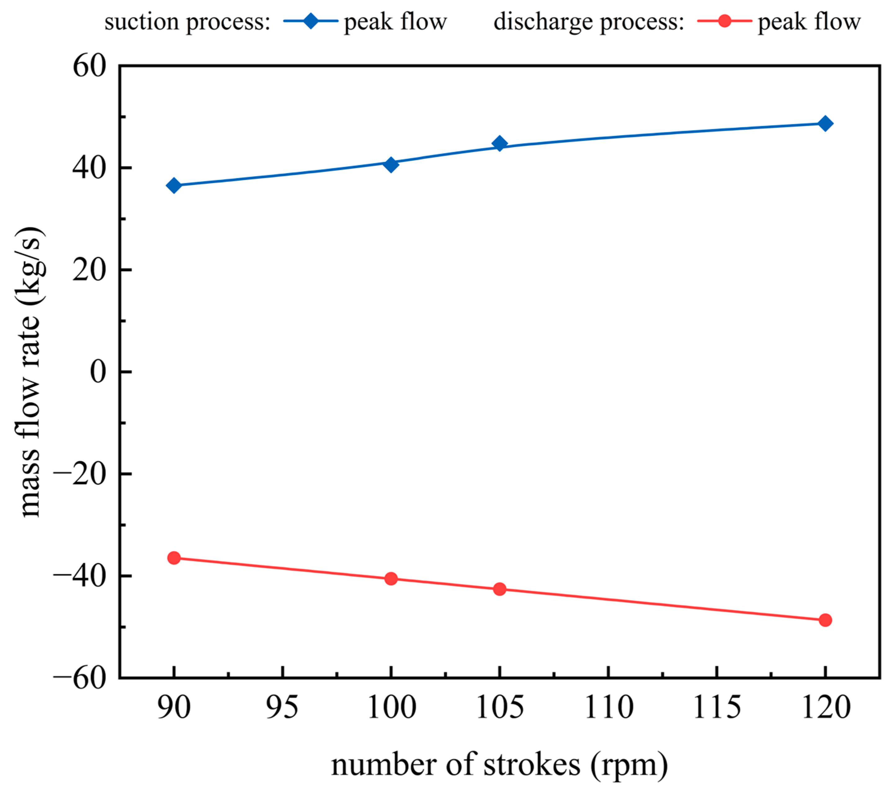
5.4. Flow Characteristic Analysis

Transient flow simulations revealed critical deviations between parametric configurations (Figure 9) and theoretical predictions (Qt_max = 40.0316 kg/s): steady-phase flow rates exhibited <6% deviation, while valve transition periods showed 113.4–114.1% discrepancies due to kinematic hysteresis (valve lag time: 0.04–0.05 s). Maximum simulated flow rates exceeded theoretical values by 6.3 ± 0.1%, correlating with amplified pressure differentials (Δpmax = 39.6 MPa) during delayed valve actuation. Valve disc velocity fluctuations synchronized with flow perturbations (Figure 6). The characteristics of the flow change when the pump valve is closed (magnified insets) show that, when the valve disc falls back to the seat, the valve flap movement oscillates due to the cushioning effect of the wave springs, resulting in a flow disturbance.
A cylindrical helical spring stiffness increase of 36% reduced peak flow by 1.5%. A wave spring stiffness boost of 24% decreased peak flow by 7.03%. A preload augmentation of 36% (110 N→150 N) suppressed peak flow variations by 2.54%. Optimized configurations achieved stabilized flow characteristics while maintaining volumetric efficiency across cycles.
Transient flow simulations elucidated the non-linear relationship between peak flow and stroke frequency (Figure 10). The parametric analysis shows that the peak flow rate in the suction/discharge phase increases simultaneously by more than 30% when the operating revolutions increase from 90 rpm to 120 rpm. This parametric response validates the active displacement control strategy presented in [1,2], which identifies stroke number as the main operating determinant for flow optimization.

6. Discussion

6.1. Valve–Flow Interaction Dynamics

6.1.1. Sealing Performance Validation

The integrated kinematic fluid dynamic analysis reveals critical insights into flow behavior during full operational cycles (T = 0.5714 s). Transient velocity profiles (Figure 5) demonstrate near-stagnant flow conditions (<0.01 m/s) within discharge valve clearance zones throughout suction phases, confirming effective sealing with negligible fluid bypass. This observation aligns with the clearance model’s predictive capability in replicating physical valve closure mechanics, as evidenced by symmetrical flow suppression patterns in suction valve regions during discharge operations.

6.1.2. Jet-Induced Valve Actuation Mechanism

Distinct flow regimes emerge during valve operation. Quiescent chamber interiors contrast sharply with localized high-velocity gradients (>600 s−1) near valve surfaces. Valve initiation triggers instantaneous jet formation (peak velocity > 12 m/s), generating transient pressure differentials (Δp > 0.3 MPa) that sustain valve opening through positive feedback. Momentum conservation analysis quantitatively links the observed leftward jet deflection (3.2 mm displacement) during suction strokes to piston-induced fluid inertia. Enhanced flow homogeneity during discharge phases (t = 1/4 T vs. t = 3/4 T) correlates with reduced recirculation intensity, suggesting improved energy efficiency.

6.1.3. Pressure-Driven Closure Optimization

The 39.3 MPa inter-pipeline pressure differential induces 16% higher jet velocities in suction valves compared to discharge counterparts. Kinematic tracking reveals a 22% reduction in closure hysteresis for suction valves (0.5 T vs. T delay), attributable to the secondary cushioning design. This hysteresis mitigation directly enhances volumetric efficiency under rated operating conditions, demonstrating the critical role of pressure differential management in valve timing optimization.

6.2. Parametric Control of Valve Dynamics

6.2.1. Dynamic Response Characteristics

Valve motion analysis (Figure 6) identifies distinct operational signatures: instantaneous opening responses manifest as velocity spikes (>2.0 m/s), characteristic of mechanical jump phenomena. The 30.08% higher mean maximum velocity in suction valves versus discharge valves reflects inherent system asymmetry. Notably, discharge valves exhibit 53.78% greater closure hysteresis during pressure equilibration, highlighting phase-dependent dynamic challenges. The number of strokes has a significant effect on the maximum lift, peak velocity, and impact velocity of the pump valve. The results provide a reliable reference for adapting the operating parameters to extend the service life of the pump valve.

6.2.2. Spring Parameter Sensitivity

Parametric studies reveal critical design constraints. Cylindrical spring stiffness increases reduce discharge valve maximum lift by 7.2% (ΔL = 1.06 mm) and velocity amplitude by 2.74%. Spring preload elevation improves positional stability (0.02% lift reduction per 10 N increment). Structural parameters exert 2.2× greater influence on closing dynamics than opening characteristics. These findings establish spring parameter optimization as a primary lever for controlling valve timing precision.

6.3. System-Level Performance Evaluation

6.3.1. Phase-Synchronized P-V Behavior

The diagnostic framework confirms stable cyclic operation across configurations (Figure 8), with pressure transitions at critical stroke points (Point 1: 39.298 MPa; Point 2: −0.348 MPa) demonstrating minimized closure hysteresis. The maintained circulation area validates operational integrity, while phase-correlated expansion/compression profiles reflect liquid compressibility and cylinder wall elasticity interactions.

6.3.2. Flow Stability Enhancement

Comparative analysis identifies Configuration 4 (24% wave spring stiffness enhancement) as optimal, eliminating pressure decay through enhanced damping. Spring optimization reduces pressure perturbations by 90% during valve transitions while maintaining volumetric efficiency. Transient flow simulations (Figure 9) reveal 6.3 ± 0.1% flow rate deviations from theoretical predictions (Qt_max = 40.0316 kg/s), attributable to kinematic hysteresis effects (0.04–0.05 s valve lag). The cushioning-induced valve oscillation during closure creates measurable flow disturbances, emphasizing the need for balanced spring dynamics. The variation in flow rate due to stroke number demonstrates the importance of balancing drilling pump performance enhancement and delaying failure of key components.

7. Conclusions

This study systematically investigated the dynamic characteristics of a novel pump valve with secondary cushioning mechanism and its impact on drilling pump performance. A comprehensive three-dimensional transient model was developed and validated to simulate actual operational processes. Fluid dynamics within the pump chamber, valve kinematics, pressure–volume characteristics, and flow dynamics under various operational conditions were analyzed through coupled numerical simulations. The principal findings are summarized as follows:
  • Sealing Efficacy Verification: complete sealing integrity was demonstrated through near-zero clearance flow velocities, validated by symmetrical flow suppression patterns.
  • Hysteresis Mitigation Strategy: the secondary cushioned mechanism design reduces closure delays by 22%, directly enhancing volumetric efficiency.
  • Parametric Optimization Guidelines: spring stiffness and preload were established as primary control parameters, with structural factors dominating closing dynamics. A wave spring stiffness enhancement of 24% achieves pressure stability through optimized damping, reducing perturbations by 90%. Increasing the number of strokes can effectively increase drilling pump displacement while exacerbating critical component failures.
These findings provide actionable design principles for minimizing energy losses and improving reliability in drilling pump systems. Future work should solve the observed flow deviation problem through experimental verification, as well as optimize the design of the secondary buffer mechanism to extend the service life of the pump valves.

Author Contributions

Conceptualization, Y.W.; methodology, Y.W.; validation, Y.W.; investigation, Y.W.; data curation, Y.W.; writing—original draft preparation, Y.W.; writing—review and editing, Y.H. All authors have read and agreed to the published version of the manuscript.

Funding

This research was funded by the Sichuan Science and Technology Support Project, grant number 2020YFG0260.

Institutional Review Board Statement

Not applicable.

Informed Consent Statement

Not applicable.

Data Availability Statement

The data presented in this study are available on request from the corresponding author. The data are not publicly available due to confidentiality requirements.

Conflicts of Interest

The authors declare no conflicts of interest.

References

  1. Josifovic, A.; Roberts, J.J.; Corney, J.; Davies, B.; Shipton, Z.K. Reducing the environmental impact of hydraulic fracturing through design optimisation of positive displacement pumps. Energy 2016, 115, 1216–1233. [Google Scholar] [CrossRef]
  2. Pei, J.; He, C.; Lv, M.; Huang, X.; Shen, K.; Bi, K. The valve motion characteristics of a reciprocating pump. Mech. Syst. Signal Process. 2016, 66–67, 657–664. [Google Scholar] [CrossRef]
  3. Brazhenko, V.; Cai, J.-C.; Fang, Y. Utilizing a Transparent Model of a Semi-Direct Acting Water Solenoid Valve to Visualize Diaphragm Displacement and Apply Resulting Data for CFD Analysis. Water 2024, 16, 3385. [Google Scholar] [CrossRef]
  4. Shu, Z.; Liang, W.; Qin, B.; Lei, G.; Wang, T.; Huang, L.; Che, B.; Zheng, X.; Qian, H. Transient Flow Dynamics Behaviors during Quick Shut-off of Ball Valves in Liquid Hydrogen Pipelines and Storage Systems. J. Energy Storage 2023, 73, 109049. [Google Scholar] [CrossRef]
  5. Yao, H.; Ye, Q.; Wang, C.; Yuan, P. CFD Dynamic Mesh-Based Simulation and Performance Investigation of Combined Guided Float Valve Tray. Chem. Eng. Process.-Process Intensif. 2023, 193, 109523. [Google Scholar] [CrossRef]
  6. Neyestanaki, M.K.; Dunca, G.; Jonsson, P.; Cervantes, M.J. A Comparison of Different Methods for Modelling Water Hammer Valve Closure with CFD. Water 2023, 15, 1510. [Google Scholar] [CrossRef]
  7. Wang, T.; Wang, G.R.; Dai, L.M.; Chen, L.Y.; Qiu, S.Z.; Li, R. Motion mechanism study on the valve disc of an ultra-high pressure reciprocating pump. Mech. Syst. Signal Process. 2021, 160, 107942. [Google Scholar] [CrossRef]
  8. Wang, G.R.; Zhong, L.; He, X.; Lei, Z.; Hu, G.; Li, R.; Wang, Y. Dynamic behavior of reciprocating plunger pump discharge valve based on fluid structure interaction and experimental analysis. PLoS ONE 2015, 10, e0140396. [Google Scholar] [CrossRef]
  9. Lian, Z.H.; Liu, Y.; Lin, T.; Li, L.; Lei, Z.; Han, C.J. Study on the fluid flow rule of five-cylinder plunger pump hydraulic end. Petroleum 2018, 4, 457–465. [Google Scholar] [CrossRef]
  10. Beune, A.; Kuerten, J.G.M.; van Heumen, M.P.C. CFD analysis with fluid-structure interaction of opening high-pressure safety valves. Comput. Fluids 2012, 64, 108–116. [Google Scholar] [CrossRef]
  11. Qian, J.; Wei, L.; Jin, Z.; Wang, J.; Zhang, H.; Lu, A. CFD analysis on the dynamic flow characteristics of the pilot-control globe valve. Energy Convers. Manag. 2014, 87, 220–226. [Google Scholar] [CrossRef]
  12. Zhang, S.C.; Zhang, Y.L.; Fang, Z.M. Numerical simulation and analysis of ball valve three-dimensional flow based on CFD. IOP Conf. Ser. Earth Environ. Sci. 2012, 15, 052024. [Google Scholar] [CrossRef]
  13. Song, X.G.; Wang, L.; Park, Y.C. Transient Analysis of a spring-loaded pressure safety valve using computational fluid dynamics (CFD). J. Press. Vessel. Technol.-Trans. ASME 2010, 132, 054501. [Google Scholar] [CrossRef]
  14. Ma, Y.; Luo, H.; Gao, T.; Zhang, Z. Transient Flow Study of a Novel Three-Cylinder Double-Acting Reciprocating Multiphase Pump. J. Fluids Eng. 2017, 139, 101101. [Google Scholar] [CrossRef]
  15. Ma, Y.; Chen, Y.; Zhang, H.; Luo, H.; Deng, H. Instability Prediction of Valve Motion and Internal Flow in Novel Large-scale Reciprocating Pump. Int. J. Fluid Mach. Syst. 2019, 12, 1–11. [Google Scholar] [CrossRef]
  16. Hwang, I.S.; Park, S.J.; Oh, W.; Lee, Y.L. Linear compressor discharge valve behavior using a rigid body valve model and a FSI valve model. Int. J. Refrig. 2017, 82, 509–519. [Google Scholar] [CrossRef]
  17. Zhang, J.; Li, Y.; Cai, S.; Zhu, H.; Zhang, Y. Investigation of gas–liquid two-phase flow in a three-stage rotodynamic multiphase pump via numerical simulation and visualization experiment. Adv. Mech. Eng. 2016, 8, 1–13. [Google Scholar] [CrossRef]
  18. Iannetti, A.; Stickland, M.T.; Dempster, W.M. A CFD model to evaluate the inlet stroke performance of a positive displacement reciprocating plunger pump. Proc. Inst. Mech. Eng. Part A J. Power Energy 2014, 5, 574–584. [Google Scholar] [CrossRef]
  19. Pan, X.; Yang, S.; Shi, Y.; Liu, Y. Investigation on the dynamic characteristics of port valves in a diaphragm pump for exhaust gas treatment system by FSI modeling. IEEE Access 2019, 7, 57238–57250. [Google Scholar] [CrossRef]
  20. Tao, W.; Guo, Y.; He, Z.; Peng, X. Investigation on the delayed closure of the suction valve in the refrigerator compressor by FSI modeling. Int. J. Refrig 2018, 91, 111–121. [Google Scholar] [CrossRef]
  21. Liu, G.; Zhao, Y.; Tang, B.; Li, L. Dynamic performance of suction valve in stepless capacity regulation system for large-scale reciprocating compressor. Appl. Therm. Eng. 2016, 96, 167–177. [Google Scholar] [CrossRef]
  22. Suh, J.; Kim, J.; Choi, Y.; Joo, W.; Lee, K. A study on numerical optimization and performance verification of multiphase pump for offshore plant. Proc. Inst. Mech. Eng. Part A J. Power Energy 2017, 231, 382–397. [Google Scholar] [CrossRef]
  23. Ma, Y.; Ni, Y.; Zhang, H.; Zhou, S.; Deng, H. Influence of valve’s lag characteristic on pressure pulsation and performance of reciprocating multiphase pump. J. Pet. Sci. Eng. 2018, 164, 584–594. [Google Scholar] [CrossRef]
  24. Zhu, G.; Dong, S.M. Analysis on the Performance Improvement of Reciprocating Pump with Variable Stiffness Valve using CFD. J. Appl. Fluid Mech. 2020, 13, 387–400. [Google Scholar] [CrossRef]
  25. Menéndez-Blanco, A.; Oro, J.M.F.; Meana-Fernández, A. Unsteady three-dimensional modeling of the Fluid–Structure Interaction in the check valves of diaphragm volumetric pump. J. Fluids Struct. 2019, 90, 432–449. [Google Scholar] [CrossRef]
Figure 1. Critical components of the drilling pump’s hydraulic end.
Applsci 15 05431 g001
Figure 2. Flow passages and cavities of the drilling pump’s hydraulic end.
Applsci 15 05431 g002
Figure 3. Schematic force diagram of the drilling pump valve with secondary cushioning mechanism.
Applsci 15 05431 g003
Figure 4. Grid independence validation in the valve disc motion region.
Applsci 15 05431 g004
Figure 5. Transient flow characteristics in the pump chamber ((left): suction process; (right): discharge process).
Applsci 15 05431 g005
Figure 6. Valve lift and velocity characteristics of suction and discharge valves under varying structural parameters.
Applsci 15 05431 g006
Figure 7. Motion characteristics of suction and discharge valves under varying operating conditions.
Applsci 15 05431 g007
Figure 8. P–V diagram of the drilling pump with secondary cushioned pump valve.
Applsci 15 05431 g008
Figure 9. Transient flow rate profiles with theoretical comparison.
Applsci 15 05431 g009
Figure 10. Peak flow rate profiles with varying operating conditions.
Applsci 15 05431 g010
Table 1. Structural parameters of the pump and valve.
Crank radius  r  (mm)178
Connecting rod length  l  (mm)890
Strokes  n  (rpm)105
Cylinder diameter (mm)160
Piston stroke (mm)356
Valve seat bore diameter (mm)90
Cylindrical spring stiffness  k 1  (N/mm)11
Cylindrical spring preload  F  (N)110
Wave spring stiffness  k 2  (N/mm)175.0548 (D100)
217.0437 (D110)
Wave spring pre-compression (mm)1
Table 2. Parametric configurations of springs.
Test No.Cylindrical SpringWave Spring
Stiffness k 1 (N/mm)Preload F (N)Stiffness k 2 (N/mm)Pre-Compression (mm)
#111110175.0541
#215110175.0541
#311150175.0541
#411110217.0441
Disclaimer/Publisher’s Note: The statements, opinions and data contained in all publications are solely those of the individual author(s) and contributor(s) and not of MDPI and/or the editor(s). MDPI and/or the editor(s) disclaim responsibility for any injury to people or property resulting from any ideas, methods, instructions or products referred to in the content.

