Article

Design and Implementation of a Vehicular Visible Light Communication System Using LED Lamps for Driving Dynamics Data Exchange in Tunnels

by
Yongtaek Woo
1,
Yeongho Park
1,
Hyojin Lim
2,† and
Yujae Song
1,*
1
Department of Robotics Engineering, Yeungnam University, Gyeongsan 38541, Republic of Korea
2
Department of Electrical and Electronic Engineering, Yonsei University, Seoul 03722, Republic of Korea
*
Author to whom correspondence should be addressed.
Affiliation updated during the editorial process.
Appl. Sci. 2025, 15(10), 5392; https://doi.org/10.3390/app15105392
Submission received: 1 April 2025 / Revised: 25 April 2025 / Accepted: 2 May 2025 / Published: 12 May 2025
(This article belongs to the Special Issue Intelligent Optical Signal Processing in Optical Fiber Communication)

Abstract

:
This study presents the design and implementation of a vehicular visible light communication (VLC) system that establishes an expandable VLC-based chain network within tunnel environments to facilitate the exchange of driving dynamics data, such as target speed and acceleration, between consecutive vehicles. The primary aim of the proposed system is to improve road safety by reducing the risk of chain collisions and hard braking events, particularly in tunnels, where limited visibility and the absence of global positioning system signals hinder drivers’ ability to accurately assess road conditions. A key feature of the proposed system is its adaptive beam alignment mechanism, which dynamically adjusts the orientation of the light-emitting diode (LED) module on the transmitting vehicle based on rhw wheel angle data estimated by the inertial measurement unit sensor. This adjustment ensures a continuous and reliable communication link with surrounding vehicles, even when navigating curves within the tunnel. Additionally, the proposed system can be integrated into actual vehicles with minimal modification by utilizing a built-in lighting system (i.e., LED taillights), offering a cost-effective and scalable solution to achieve the objective.

1. Introduction

Recent advances in connected car technology have pushed vehicle-to-everything (V2X) research toward faster, more reliable, and spectrum-efficient data links [1,2]. Traditionally, dedicated short-range communications and cellular V2X have dominated this space, yet both rely on congested radio frequency (RF) bands and are vulnerable to multipath fading and electromagnetic interference [3,4]. Against this backdrop, vehicle-to-vehicle (V2V) communication based on visible light communication (VLC) has emerged as a compelling alternative that exploits the unlicensed, gigahertz wide optical spectrum already available through automotive light-emitting diode (LED) head and tail lights [5,6]. Since LEDs can be modulated at megabit per second rates without altering their primary illumination function, VLC offers inherently high data throughput, sub-millisecond latency, and a narrow optical beam that limits eavesdropping, thereby enhancing link security [7,8]. These attributes are key enablers for the next generation of cooperative driving functiosn–platooning, cooperative adaptive cruise control, and collision avoidance maneuvers–that require the hard real-time exchange of kinematic data among neighboring vehicles.
Tunnel environments magnify both the need and the opportunity for VLC-based V2V systems [9,10]. First, global positioning system (GPS) signals are typically unavailable or severely attenuated in tunnels, depriving on-board units of absolute positioning and time references [11]. Second, the curved walls and low ambient light impair a driver’s line of sight (LoS), so a single incident can quickly propagate into a multi-car pile up if the following vehicles receive no early warning [12]. VLC leverages the existing vehicle lighting infrastructure, which is always active in tunnels due to traffic regulations, to form an optical safety net that carries real-time speed, acceleration, and hazard flags beyond the driver’s visual horizon. Despite these clear advantages, deploying VLC-for-V2V communication in practice poses non-trivial engineering challenges. The narrow emission patterns of automotive LEDs demand continuous beam alignment between the transmitter and receiver as vehicles weave through curved lanes or change their relative altitude. Optical channels inside tunnels also experience fluctuating background illumination from emergency lights, reflective signage, and oncoming traffic, which introduces shot noise and saturation effects in photodetectors. In addition, water droplets, exhaust haze, and surface contaminants on lamp covers scatter and attenuate the optical signal. Finally, the stringent cost and retrofit constraints of mass-market vehicles restrict the complexity and power budget of any add-on VLC module.
To address these issues, several studies have explored the development and implementation of vehicular VLC systems, as demonstrated in [13,14,15,16,17,18,19,20,21,22,23,24]. The study in [13] presented a V2V communication system utilizing VLC technology, where communication is established via LED transmitters and a camera-based receiver. The LED transmitter transmits various forms of data through optical signals. The camera receiver is equipped with a specialized optical communication image sensor that features a communication pixel array for high-speed optical signal reception, as well as a flag image output function that enhances LED detection, particularly in outdoor environments. The work of [14] experimentally analyzed the effect of the fog condition in the vehicular VLC system. The experimental results demonstrated that the vehicular VLC system introduced in [14] offered a reliable V2V data transmission over a fog-impaired optical channel with a relatively high signal-to-noise ratio (SNR), even under heavy-fog conditions. The authors in [15] demonstrated an IEEE 802.15.7-compliant VLC physical layer that repurposes commercial LED fog lamps as transmitters of low-latency safety beacons in LoS V2V links. Their field measurements showed that the standard readily supports V2V operation and maintaining the target bit error rate (BER) across varying inter-vehicle spacings requires judicious selection of the modulation–coding scheme. The study also quantified the narrow emission and reception cones of off-the-shelf fog lamps, supplying practical design constraints for the large-scale deployment of vehicular VLC. The study in [16] proposed an optical camera communication system integrated into vehicles, utilizing the existing LED lights in cars and standard cameras. This system enables region-of-interest signaling functionality for vehicles through their headlights or taillights. In [17], a vehicle positioning system based on V2V and Vehicle-to-Infrastructure (V2I) visible light communication was examined. In this system, a camera sensor captures the location information of LEDs mounted on tunnel infrastructure and vehicle taillights. The visible light signals carry predetermined location data and are reliably detected by the camera due to the high directivity of the visible light propagation, providing an effective solution for vehicle positioning in controlled environments like tunnels. The authors in [18] designed a VLC system featuring a transmitter and receiver tailored to V2V applications, highlighting its characteristics and capabilities. They demonstrated how VLC technology could be integrated with traffic signals to communicate with vehicles’ LED lights, suggesting that this approach could potentially reduce the number of accidents. In [19], a prototype design of a VLC-based V2V system was presented for communicating hard brake warnings to the following vehicle. The system was designed with the primary goal of ensuring timely awareness of the hard braking action of a leading vehicle, which served as the key motivation for its development. The study of [20] presented a low-cost enhancement of vehicular communication networks (VCNs) for future intelligent transportation systems. It combined VLC, using white LEDs that were already installed in headlamps, with a custom control area network (CAN) bus interface accessed through the vehicle’s on-board diagnostics port. Laboratory tests showed error-free VLC beaconing over a 1.5 m link, while the CAN interface reported a vehicle speed with high fidelity to a GPS reference. The results indicated that VLC beacons, if paired with inexpensive in vehicle data extraction, can bolster VCN robustness without costly RF spectrum requirements. The work of [21] introduced a bidirectional vehicular VLC demonstrator that uses unmodified motorcycle head- and rear-lamp assemblies as optical transceivers. Field tests were performed outdoors under full daylight, covering inter-vehicle spacings up to 30 m as well as multiple lateral and angular offsets. Link quality was mapped through the spatial distributions of SNR and the associated packet error rate, evaluated at symbol rates of 28 kBd and 57 kBd. These results established a reference data set for assessing full duplex VLC performance in realistic V2V scenarios. The authors in [22] proposed enhancing V2V communication through incorporating imaging receivers equipped with fresnel, aspherical, and combined lenses, mounted on the rear of receiving vehicles. Communication was established through the headlamps of the transmitting vehicle to the imaging receivers on the destination vehicle’s rear. The study further revealed that V2V communication performance diminishes as the angle of incidence increases, primarily due to the reduction in received power. In [23], a field-programmable gate array-based vehicular VLC prototype was developed, utilizing a standard low-beam headlamp as an on–off keying (OOK) transmitter and a Zynq-7000 device to perform encoding, modulation, and demodulation functions. To enhance the signal reception, a 25.4 mm biconvex lens was positioned in front of the photodetector, allowing for reliable operation under daylight conditions at distances of up to 20 m. Field evaluations demonstrated a stable SNR, low packet loss, and acceptable BER, supporting the practicality of VLC for short-range V2V communication. The work of [24] presented a rate-adaptive orthogonal frequency division multiplexing (OFDM) vehicular VLC prototype implemented on a software-defined radio (SDR) platform. The system employed direct current-biased optical OFDM at the physical layer and supported dynamic modulation adaptation among multiple schemes. A lightweight OOK feedback link was used to transmit real-time channel state information from the receiver to the transmitter, enabling the selection of the highest-order modulation that satisfied a predefined BER threshold. These initial results demonstrated the potential of adaptive OFDM-based VLC to achieve high-throughput, reliable V2V communication in future 6G vehicular networks.
Despite numerous existing works on the implementation of vehicular VLC systems, including [13,14,15,16,17,18,19,20,21,22,23,24], there remains a significant gap in studies addressing beam alignment issues, which are critical for ensuring seamless V2V link connections between vehicles via VLC. Furthermore, there is limited research providing a detailed explanation of how the developed VLC systems are integrated into LED lamps in actual vehicles and how they operate.
Based on the above discussion, the main contributions of this work are summarized as follows:
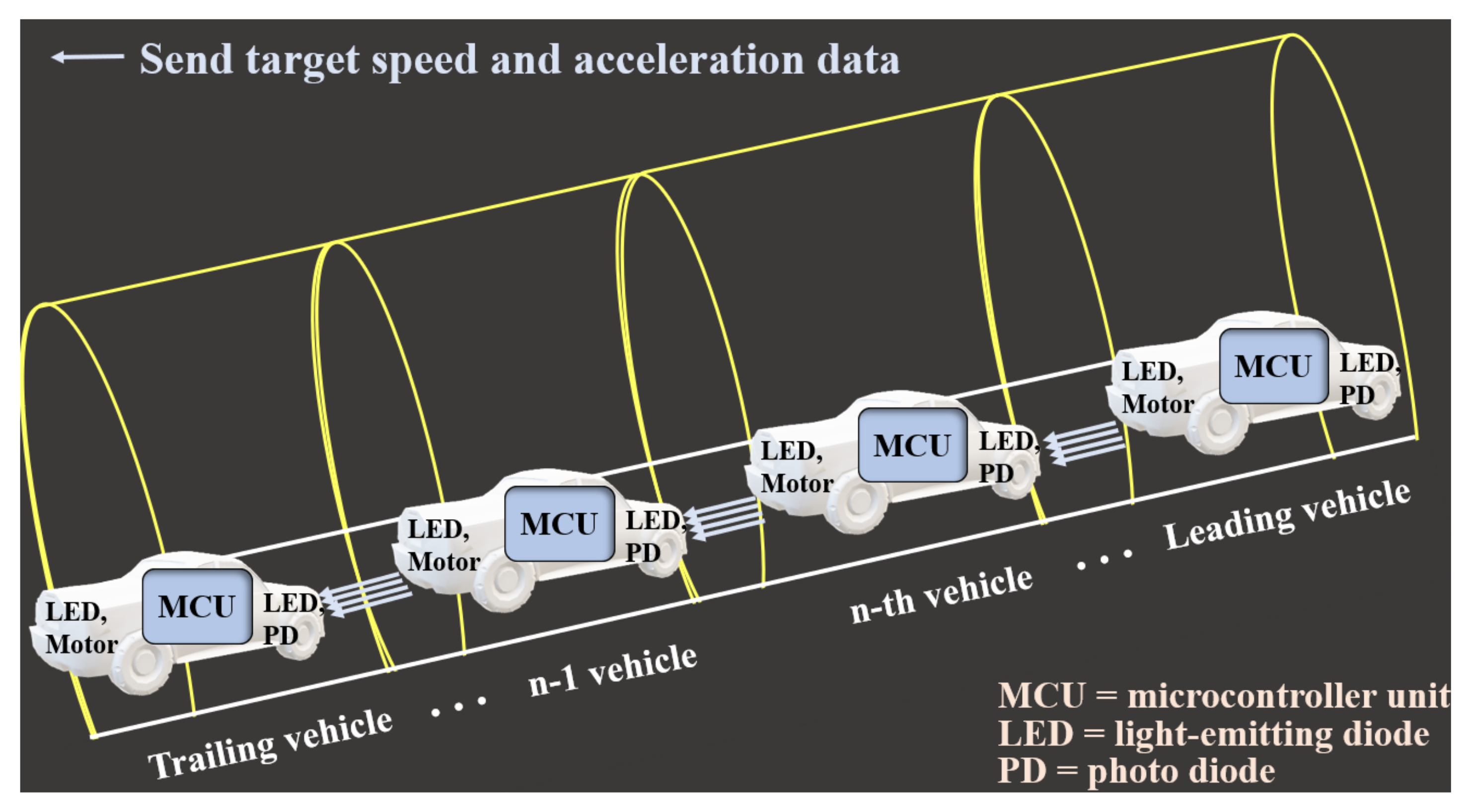
  • We propose and implement a vehicular VLC system designed to establish an expandable VLC-based chain network for the real-time exchange of driving dynamics data (e.g., target speed and acceleration) among consecutive vehicles in tunnel environments. The system is tailored for GPS-denied scenarios, where limited visibility and poor situational awareness increase the risk of chain collisions. The system architecture is validated through experimental scenarios representative of real-world tunnel hazards, including sudden braking and unexpected congestion.
  • To ensure reliable optical links even during curved driving, the system incorporates an adaptive LED beam alignment mechanism that dynamically adjusts the transmitter’s orientation based on yaw angle, derived from a nine-axis inertial measurement unit (IMU). This closed-loop control significantly enhances communication stability in conditions where traditional fixed-beam VLC systems are prone to misalignment.
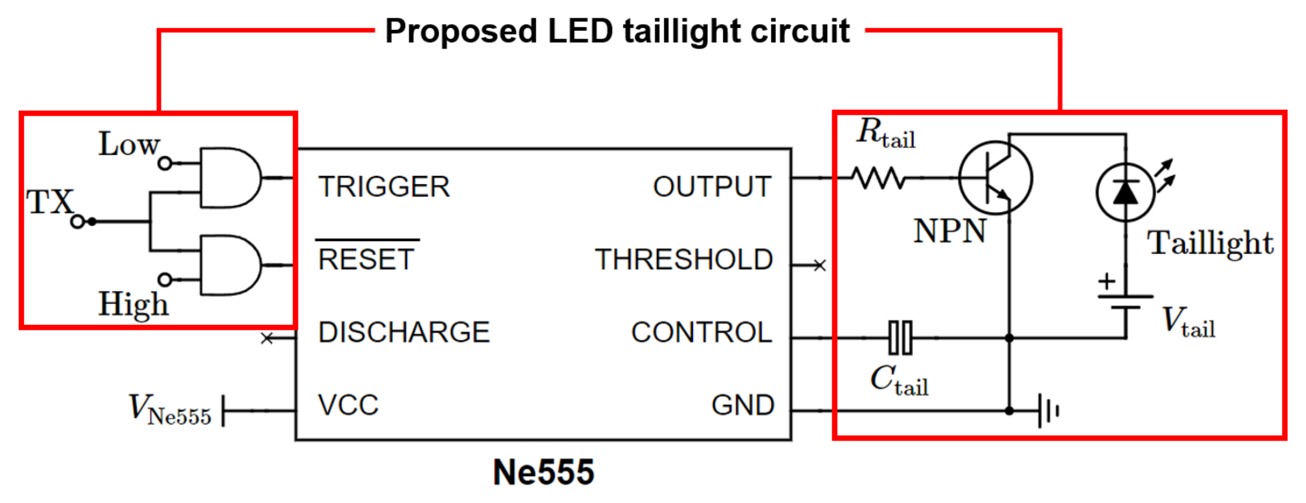
  • The proposed system can be practically deployable in existing vehicles with minimal hardware modification, as it reuses built-in LED tail-lights as VLC transmitters and requires only low-cost embedded circuitry. This makes the approach both cost-effective and scalable, offering a feasible path toward the real-world adoption of VLC-based V2V communication.

2. System Description

We consider a VLC-based chain network among vehicles driving within a tunnel, as illustrated in Figure 1. In this scenario, each vehicle is assumed to exchange its driving dynamics data (e.g., target speed and acceleration) with neighboring vehicles ahead and behind. According to the findings in [25], incorporating target speed and acceleration data in cooperative adaptive cruise control significantly improves traffic stability and response times. Moreover, in this work, the wheel angle data are employed for adaptive optical beam alignment, which will be explained in the next section, between consecutive vehicles. The primary objective of this data exchange is to enhance road safety by mitigating the risks of chain collisions and hard braking in tunnels, where limited visibility and the lack of GPS signals result in various problems, such as a lack of real-time traffic updates and incorrect next-turn guidance. For data exchange between vehicles within the tunnel, we adopted V2V communication with the VLC system, where each vehicle utilizes its existing LED tail-lights for data transmission and photo-diodes (PDs) installed at the front of the vehicle for data reception. Additionally, each vehicle is equipped with a microcontroller unit (MCU) for processing the exchanged data and controlling the servo-motor, enabling adaptive optical beam alignment for optimized communication.

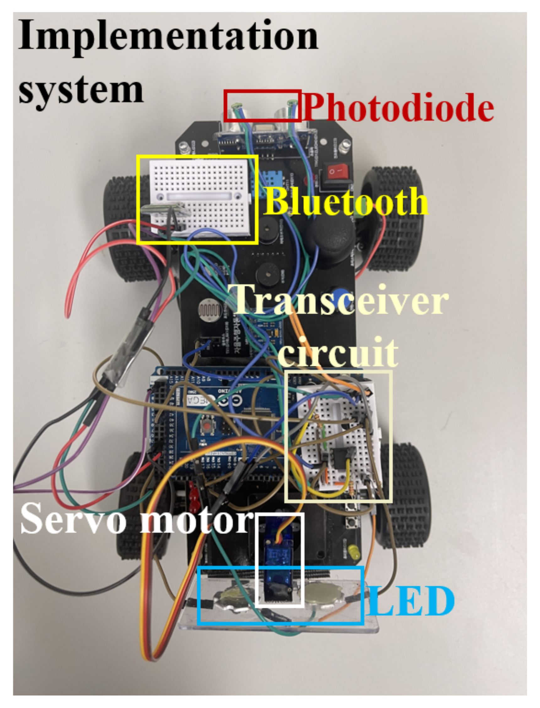
3. Implementation of Vehicular VLC System
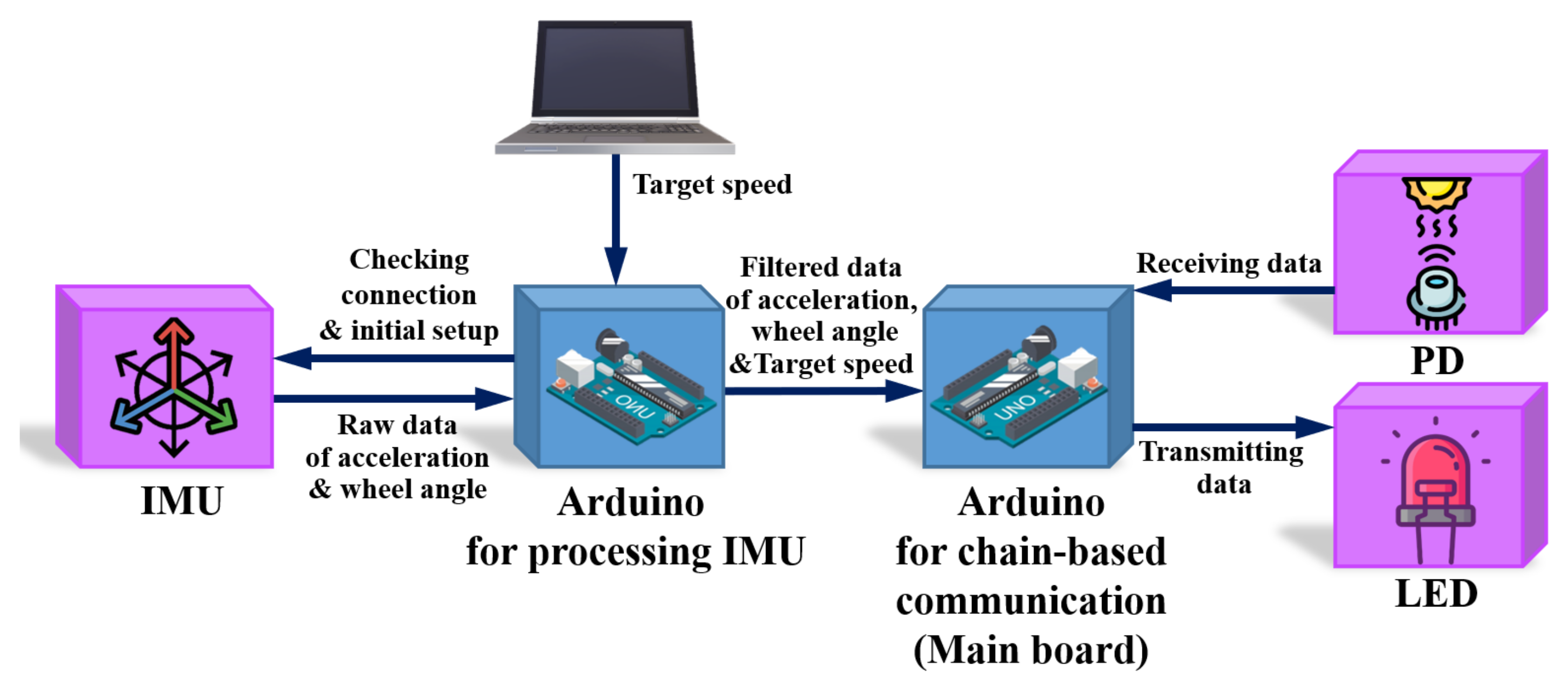
In this section, we provide detailed descriptions of the hardware components, communication protocols, and the overall system architecture of the proposed vehicular VLC system installed in each vehicle. This system facilitates real-time data exchange between vehicles, ensuring synchronized movement and improved road safety in tunnel environments.

3.1. Main Board

The proposed vehicular VLC system utilizes an Arduino Mega board as the main control unit, which provides numerous input/output ports and supports asynchronous serial communication. The proposed vehicular VLC system incorporates the MPU-9250 nine-axis IMU sensor from SMG, which includes a three-axis gyroscope, three-axis accelerometer, and three-axis magnetometer. The MPU-9250 delivers real-time data, with the digital low-pass filter frequency set at 10 Hz, an accelerometer range of ±2 G, and a gyroscope range of ±250 degrees per second. A complementary filter is applied to combine data from the magnetometer and gyroscope, enabling precise calculation of the yaw rotation angle. The yaw rate is then used to adjust the orientation of the LED tail-light in proportion to the vehicle’s turns for seamless VLC between consecutive vehicles; this is achieved through a servo-motor that operates in conjunction with the LED tail-light.
To ensure the reliable and real-time operation of multiple time-sensitive processes, the proposed vehicular VLC system employs two separate Arduino Mega boards. One board is dedicated to acquiring orientation data from the IMU, while the other is responsible for processing the data from LED and PD, controlling the servo-motor for beam alignment, and managing vehicle movement. This separation of tasks is necessary to prevent timing conflicts and ensure deterministic performance, as initial testing with a single microcontroller showed instability in both communication and actuation. The interconnection between the two boards is managed via serial communication, as illustrated in Figure 2. The proposed vehicular VLC system requires up to 140 ms to ensure entire functionality in the worst-case timing scenario. The first Arduino Mega running the IMU operates with a 4.7 V battery pack, while the second board is powered by a 5.1 V battery pack.

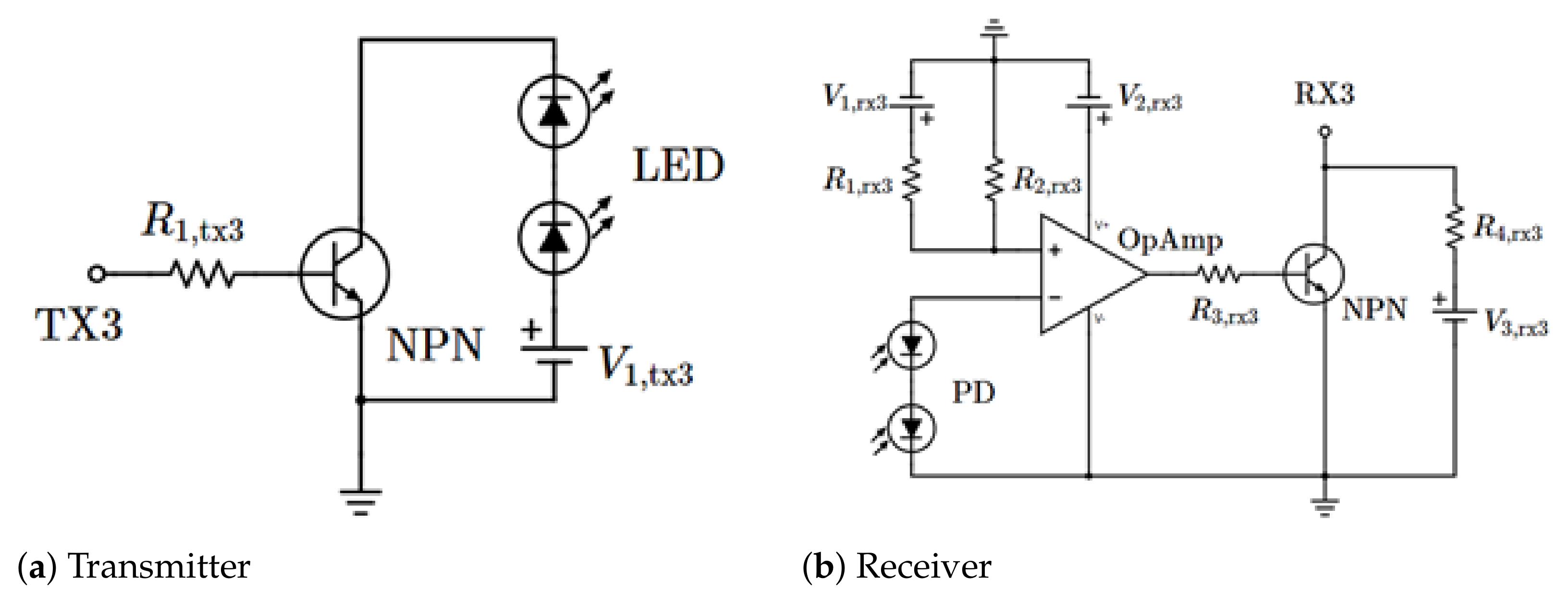
3.2. Transmitter and Receiver

For VLC, LEDs function as the light source, providing a wide viewing angle that facilitates easier alignment between the transmitter and receiver. In this system, the PHOTRON PP625-8L615-STAR LED is utilized, which operates within the 615–645 nm wavelength range and delivers 1 W of output power, accompanied by a lens that provides a 125-degree viewing angle. As illustrated in Figure 3a, serial communication through the Arduino Mega’s pin transmits binary signals of 0 V and 5 V, controlling the LED via an MPS2222A transistor. To prevent overvoltage, two LEDs are connected in series, ensuring stable current flow. For signal detection, a Broadcom AFBR-S4K11C0125B avalanche PD is employed, as shown in Figure 3b. With a rise time of 110 ps, the PD generates a signal between 0 and 0.6 V. To amplify the signal to the receiver’s 2 V threshold, an LM2904N amplifier is used. A reference voltage of 400 mV is set using a voltage divider. If the PD’s output exceeds this reference voltage, the amplifier outputs 0 V; otherwise, it outputs 5 V. When two PDs are connected in series, they produce up to 1.2 V, which is digitized by a transistor, with 5 V representing binary 1 and 0 V representing binary 0 at the RX pin.

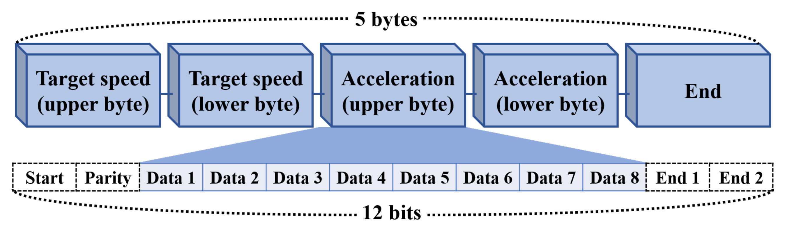
3.3. Packet Design and Timing Requirements for Vehicular VLC System

The proposed vehicular VLC system adopts asynchronous serial communication with a baud rate of 1200, and it was designed to transmit one data packet every 50 ms using a timer. As illustrated in Figure 4, each data packet consists of 2 bytes of target speed data, 2 bytes of acceleration data, and 1 byte of end data, respectively. Each byte contains 8 data bits, and they are transmitted with 1 start bit, 1 parity bit, and 2 end bits, resulting in a total of 60 bits transmitted per cycle. Figure 4 presents an illustration of the packet design used in the proposed vehicular VLC system.

3.4. Adaptive LED Beam Alignment Mechanism

For seamless VLC between consecutive vehicles, the proposed vehicular VLC system incorporates an adaptive LED beam alignment mechanism, which is developed in this study. A key component of this mechanism is the servo-motor integrated with the transmitting vehicle’s LED module. Specifically, we utilized the SG-90 model of servo-motor, manufactured by OEM, which can be easily controlled via pulse-width modulation through the main board. The servo-motor adjusts the orientation of the LED module on the transmitting vehicle to align with the PD of the following vehicle.
In the proposed beam alignment mechanism, the acceleration and yaw rotation angle are computed using data from the IMU sensor. Let A x ( t ) , A y ( t ) , A z ( t ) A ( t ) be the acceleration (in m/ s 2 ), G x ( t ) , G y ( t ) , G z ( t ) G ( t ) be the angular velocity (in rad/s), and M x ( t ) , M y ( t ) , M z ( t ) M ( t ) be the magnetic flux density (in Tesla) at time t, respectively. These quantities are computed from the nine-axis raw data of the IMU sensor (i.e., A raw ( t ) , G raw ( t ) , and M raw ( t ) ) as follows:
A ( t ) = g S A A raw ( t ) , G ( t ) = 1 S G G raw ( t ) , M ( t ) = M raw ( t ) K ,
where S A and S G are the sensitivities of the accelerometer and gyroscope, respectively, g is the gravitational acceleration, and K is the coefficient of the magnetometer. The z-axis angular velocity, denoted as G z ( t ) , is typically obtained from the IMU sensor. However, due to the potential for ambient noise during data acquisition, a more robust estimation of G z ( t ) is achieved by incorporating both the angular velocity G ( t ) and the magnetic flux M ( t ) . This approach leverages a complementary filter, which combines the advantages of both data sources to provide a more accurate and noise-resistant estimation of the z-axis angular velocity. More specifically, the z-axis angular velocity computed using M ( t ) , denoted as G z , M ( t ) , is derived from the rate of change in yaw M ( t ) , as given by
G z , M ( t ) = yaw M ( t ) yaw M ( t 1 ) Δ t ,
where ya w M t = atan 2 M x t , M y t , and Δ t is time interval. Finally, the z-axis angular velocity after filtering, denoted as G z , filt ( t ) , can be represented as follows:
G z , filt t = α G z t + ( 1 α ) · G z , M t ,
where α is the coefficient of the complementary filter. Consequently, to align the LED beam between consecutive vehicles, particularly when navigating curves, the regulated G z , filt ( t ) is used as an input to control the servo-motor. This allows for precise adjustments in the LED module’s orientation, ensuring a stable communication link between vehicles. The proposed LED beam alignment mechanism is outlined in Algorithm 1.
Algorithm 1 Adaptive LED beam alignment mechanism.
1:
Perform initial setup and offset calibration.
2:
while Initial offset calibration is carried out. do
3:
    Receive raw data from each axis and convert units.
4:
    Integrate acceleration, gyroscope, and magnetic data.
5:
    Apply complementary filter.
6:
    Adjust servo-motor angle based on the angular velocity.
7:
    Transmit current vehicle’s data to main board.
8:
end while

3.5. Integration of the Proposed Vehicular VLC System to Actual Vehicles

Figure 5 illustrates the potential integration of the proposed vehicular VLC system with a vehicle’s LED tail-light. We utilize a single precision timer, the Ne555, which is commonly employed in existing LED tail-light and headlight lamps. The Ne555 timer operates in monostable, astable, and bistable modes. For our communication application, the bistable mode is used. In this mode, the trigger and (inverted) reset terminals are essential. When the trigger terminal voltage drops below 1/3 Vcc, the output switches to a high state. Similarly, a low signal at the (inverted) reset terminal sets the output to low, as both terminals are unresponsive to high signals. As depicted in Figure 5, an AND gate is placed before the trigger and (inverted) reset terminals, enabling the system to receive binary 1 and 0 from the TX. These signals send a low voltage to the trigger and reset terminals, controlling the tail-light lamp based on the output state. Additionally, a capacitor is connected to the control terminal to stabilize the circuit. The threshold and discharge terminals are essential to the system’s operation outside the communication circuit. According to Texas Instruments, the Ne555’s output pulse rise and fall times are 100 ns, ensuring sufficient data exchange for the proposed vehicular VLC system.

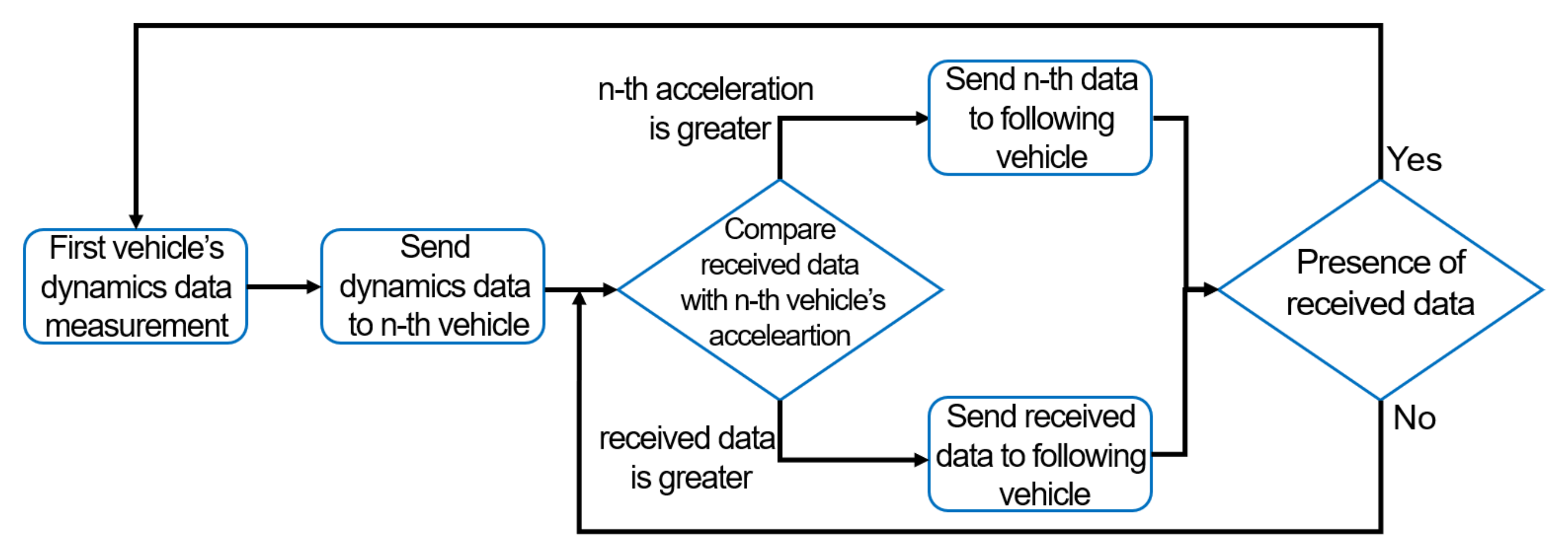
3.6. Proposed Mechanism of Data Exchange in a VLC-Based Chain Network in the Tunnel

We describe a mechanism of data exchange between vehicles driving within a tunnel via the considered VLC-based chain network, which can help to mitigate chain collisions and hard braking incidents in tunnel environments. To facilitate understanding, we consider the proposed VLC-based chain network involving three vehicles (i.e., leading, middle, and trailing vehicles) within a tunnel. The leading vehicle measures its target speed and acceleration and transmits the measured data to the middle vehicle. After receiving the data, the middle vehicle compares the incoming acceleration with its own. If the received acceleration is greater, which suggests that the leading vehicle is accelerating faster, the middle vehicle forwards the received data to the trailing vehicle. On the other hand, if the middle vehicle’s acceleration is higher, it sends its own acceleration data to the trailing vehicle. Once the trailing vehicle receives the data from the middle vehicle, it compares the received acceleration to its own and continues communication between the vehicles. When the distance between consecutive vehicles increases beyond the effective VLC communication range, the communication link naturally becomes unavailable. However, in such cases, this is interpreted as an indirect indicator of low collision risk: a vehicle that is sufficiently far from its predecessor has more time and space to respond safely, thus reducing the urgency of real-time coordination. Accordingly, in our system logic, if a vehicle fails to receive data, it transitions into a leading-role behavior and begins broadcasting its own data to downstream vehicles. The process of data exchange between vehicles in the considered network can be illustrated as a flow chart, as shown in Figure 6.
Table 1 compares the proposed vehicular VLC system, the vehicular VLC system and controller area network (CAN) bus interface [20], the existing vehicular optical wireless communication system [26], and RF-based tunnel communication systems [27], focusing on cost, communication method, and scalability. The proposed vehicular VLC system reuses each vehicle’s existing LED lamps as the transmitter and receiver. Also, the proposed vehicular VLC system is implemented using low-cost MCU hardware (e.g., Arduino Mega), making it extremely economical. By maintaining an LOS V2V chain topology, it can relay data between vehicles without any tunnel-mounted infrastructure, ensuring reliable in-tunnel communication. In contrast, the vehicular VLC system and CAN bus interface require expensive equipment for their implementation (e.g., USRP-2922) and their performance may degrade due to NLOS. Additionally, the vehicular optical wireless communication system requires custom LED overdrive modules, an expensive photodetector (e.g., PDA100A2), and additional optical components (band-pass filter and lens), resulting in high implementation costs. Vehicular optical wireless communication systems support only point-to-point (P2P) links and the performance degrades under non-line of sight (NLOS) conditions. The existing optical wireless V2V communication system has not yet been applied to real vehicles. However, RF-based tunnel communication incurs substantial costs for on-board units (OBUs) and roadside units (RSUs), requires space for RSU deployment and backhaul cabling, and suffers from scalability bottlenecks when many OBUs share a single RSU. This comparison demonstrates that the proposed vehicular VLC system offers superior practical feasibility—delivering cost-effective, infrastructure-free V2V communication in tunnels compared to prior optical or RF communication approaches.

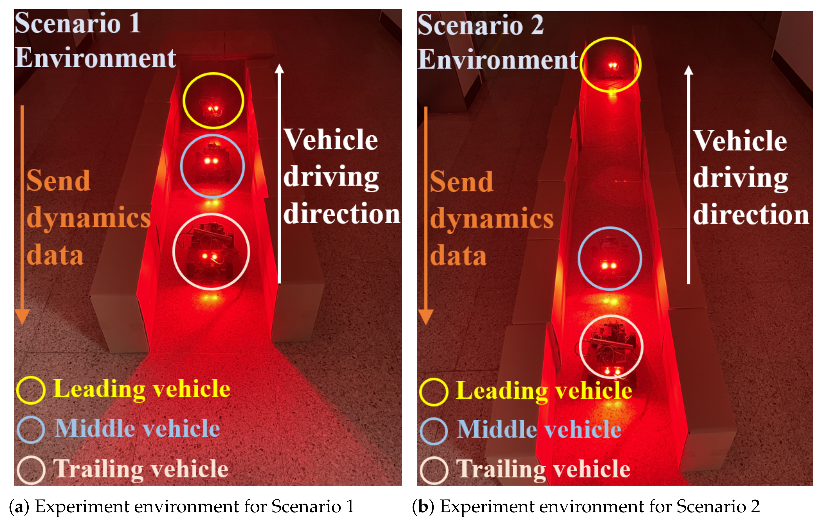
4. Experimental Results

To validate the effectiveness of the proposed vehicular VLC system, empirical experiments were conducted through implementing the proposed vehicular VLC system on the RB073 Arduino Car Learning Kit, as depicted in Figure 7. A VLC-based chain network was established using three vehicles (i.e., leading, middle, and trailing vehicles) driving within a tunnel scenario, as illustrated in Figure 8. The use of three vehicles is sufficient to demonstrate the core functionality and practicality of the proposed VLC-based chain communication network, particularly in sequential vehicle scenarios where multi-hop communication, dynamic beam alignment, and data handoff are critical. The middle vehicle, in particular, plays a pivotal role in receiving, comparing, and relaying the driving dynamics data between the leading and trailing vehicles, thereby simulating a realistic multi-node communication flow. In the current design, communication is limited to vehicles in the same lane, forming a linear VLC chain. While vehicles in adjacent lanes may introduce potential optical interference, this effect is minimized in our setup through the use of adaptive optical beam alignment, which continuously adjusts the LED orientation to maximize the signal-to-interference-plus-noise ratio (SINR) between consecutively aligned vehicles.
The experiments evaluate the proposed vehicular VLC system under two distinct scenarios that represent common accident risks within tunnels. The first scenario (called Scenario 1), as illustrated in Figure 8a, involves vehicles driving at regular intervals when the leading vehicle suddenly halts. The second scenario (called Scenario 2), as illustrated in Figure 8b, considers a situation where a vehicle encounters unexpected traffic congestion while driving at a normal target speed. These scenarios were chosen to assess the system’s ability to prevent chain collisions and hard braking incidents by enabling real-time data exchange between vehicles.
To facilitate the monitoring and recording of real-time driving dynamics during empirical experiments, the proposed vehicular VLC system integrated Bluetooth communication through pairing the HC-06 Bluetooth modules installed at each vehicle with a laptop computer, which plays the role of data server. The data received from each vehicle were transmitted via a Bluetooth serial connection and logged using PuTTY software, which enables the collection of structured log files for subsequent analysis. The recorded data were then processed and visualized in graphical form, providing deeper insights into system performance and the effectiveness of the proposed communication scheme under various experimental conditions.

4.1. Experimental Results in Scenario 1

Figure 9 first demonstrates the proposed vehicular VLC system’s ability to transfer driving dynamics data (e.g., the acceleration data in this experiment) between the leading and middle vehicles within a tunnel. The figure highlights that the communication link between the two vehicles remains highly reliable, with a maximum error of 0.76, even during hard braking events where acceleration sharply decreases. Moreover, Figure 9 illustrates the functionality of the data exchange mechanism described in Section 3.6. As shown, the middle vehicle compares its own acceleration data with the data received from the leading vehicle to decide which value to transmit to the trailing vehicle. The experiment confirms that the middle vehicle successfully selects and transmits the smaller of the two values, ensuring the accuracy of the information passed along the chain. Finally, Figure 9 provides a comparison between the data transmitted by the middle vehicle and the data received by the trailing vehicle. This experiment, conducted using a scenario where vehicles are driving at regular intervals and the leading vehicle makes a sudden stop, demonstrates that the VLC-based chain network enables reliable communication in the tunnel, effectively transmitting hard braking information to prevent chain collisions.

4.2. Experimental Results in Scenario 2

Scenario 2 involves an experimental setup where the leading vehicle is stationary within a tunnel due to traffic congestion, while the middle vehicle approaches, unaware of the stationary condition ahead. In this scenario, the target speed can be computed by using the motor control data from the IMU sensor, and both the target speed and acceleration of the stationary vehicle are zero. In Figure 10, we can observe how the proposed vehicular VLC system transmits the driving dynamics data (e.g., target speed and acceleration in this experiment) between vehicles in the tunnel. At the beginning of the experiment, the middle vehicle is outside the communication range of the stationary leading vehicle, resulting in there being no data reception. Consequently, the middle vehicle continues to transmit its own acceleration data to the trailing vehicle. However, as it enters the communication range and receives data indicating that there is congestion ahead, it compares the received acceleration data with its own (i.e., middle vehicle) acceleration and transmits the lower value to the trailing vehicle. Figure 10b displays the target speed data under the same conditions as in Figure 10a. Initially, when the middle vehicle does not receive data from the stationary leading vehicle, it transmits only its own data. Upon receiving data from the stationary vehicle, the middle vehicle compares both sets of data and transmits the appropriate updated data to the trailing vehicle. Finally, in Figure 10, we compare the data transmitted by the middle vehicle with the data received by the trailing vehicle. This comparison confirms that even when a vehicle traveling at normal target speed encounters an unexpected stationary situation, the proposed vehicular VLC system ensures reliable communication, thereby preventing potential accidents.

4.3. Experimental Results of the Proposed Vehicular VLC System Under Various Scenarios

To validate the adaptive beam alignment system in the proposed vehicular VLC system, we conducted an additional empirical experiment. In this experiment, the system’s performance was analyzed through a comparison of two cases: (i) with the adaptive beam alignment system activated and (ii) without adaptive beam alignment. The measurements were carried out while varying the misalignment angle between the transmitter and receiver of consecutive vehicles. As shown in Figure 11, the system incorporating the adaptive beam alignment maintained a stable SINR across the considered range of misalignment angles. In contrast, the system without adaptive alignment exhibited a significant degradation in SINR as the misalignment angle increased. These findings demonstrate the critical role of the adaptive beam alignment system in preserving communication robustness, particularly under the non-ideal alignment conditions commonly encountered in real driving scenarios.
In addition, Figure 12 shows the SINR performances of the proposed system under two conditions—with and without tunnel lighting—while varying the misalignment angle between the transmitter and receiver of consecutive vehicles. Since tunnel lighting typically uses white LED light, we replicated this condition in our experiment by using a comparable white LED light source to simulate realistic tunnel lighting interference. In Figure 12, it is identified that when the transmitter and receiver are well-aligned (i.e., misalignment angle = 0°), the presence of tunnel lights causes a slight reduction in SINR, but the overall performance remains robust. However, as the misalignment angle increases, the impact of tunnel lighting becomes more pronounced, leading to a larger degradation in the SINR. This indicates that tunnel lighting can act as a significant source of external interference, particularly when the optical beams are not perfectly aligned. These findings highlight the critical importance of the adaptive beam alignment system integrated into our design, which helps maintain a strong SINR even in the presence of ambient tunnel lighting. Furthermore, the results confirm that external lighting conditions must be carefully considered when designing and deploying VLC-based vehicular communication systems in real-world environments.
Furthermore, we also conducted an empirical experiment to evaluate the feasibility of using a commercial LED tail-light as a transmitter in our VLC system. The results of this experiment are presented in Figure 13, which shows the SINR (in dB) and signal and noise power levels (in dBm) at varying distances between the transmitter and receiver. As expected, the SNR decreases as the distance increases, but the trend and absolute values confirm the feasibility of using vehicular LED tail-lights as VLC transmitters when supported by a suitable optical receiver design.

5. Conclusions

This paper introduced a novel vehicular VLC system aimed at improving road safety in tunnel environments. The system utilizes adaptive beam alignment to maintain reliable communication between vehicles, even when navigating curves. Additionally, this can be seamlessly integrated into existing vehicles by repurposing built-in LED tail-lights as communication sources, which required minimal modification. The empirical experiments conducted with the RB073 Arduino Car Learning Kit demonstrated the system’s effectiveness in transmitting real-time driving dynamics data, such as target speed and acceleration, between vehicles. The results indicate the system’s ability to sustain stable communication links in various tunnel scenarios, including sudden stops and traffic congestion, showcasing its potential to reduce the risk of chain collisions in GPS-deprived settings.

Author Contributions

Conceptualization, Y.W.; methodology, Y.P. and H.L.; validation, Y.W. and Y.P.; validation, H.L.; supervision, Y.S.; project administration, Y.S.; funding acquisition, Y.S. All authors have read and agreed to the published version of the manuscript.

Funding

This work was supported in part by the project titled “Development of Polar Region Communication Technology and Equipment for Internet of Extreme Things (IoET)”, funded by Ministry of Science and ICT (MSIT), Korea.

Institutional Review Board Statement

Not applicable.

Informed Consent Statement

Not applicable.

Data Availability Statement

The original data underlying this study are available from the co-authors listed above upon reasonable request.

Acknowledgments

We extend our sincere thanks to our colleagues and students for their unwavering support throughout this research. We are especially grateful to all participants in experiments for generously sharing their time and insights.

Conflicts of Interest

The authors declare no conflict of interest.

References

  1. Gyawali, S.; Xu, S.; Qian, Y.; Hu, R.Q. Challenges and Solutions for Cellular Based V2X Communications. IEEE Commun. Surv. Tutor. 2021, 23, 222–255. [Google Scholar] [CrossRef]
  2. Clancy, J.; Mullins, D.; Deegan, B.; Horgan, J.; Ward, E.; Eising, C.; Denny, P.; Jones, E.; Glavin, M. Wireless Access for V2X Communications: Research, Challenges and Opportunities. IEEE Commun. Surv. Tutor. 2024, 26, 2082–2119. [Google Scholar] [CrossRef]
  3. Abboud, K.; Omar, H.A.; Zhuang, W. Interworking of DSRC and Cellular Network Technologies for V2X Communications: A Survey. IEEE Trans. Veh. Technol. 2016, 65, 9457–9470. [Google Scholar] [CrossRef]
  4. Garcia, M.H.C.; Molina-Galan, A.; Boban, M.; Gozalvez, J.; Coll-Perales, B.; Şahin, T.; Kousaridas, A. A Tutorial on 5G NR V2X Communications. IEEE Commun. Surv. Tutor. 2021, 23, 1972–2026. [Google Scholar] [CrossRef]
  5. Memedi, A.; Dressler, F. Vehicular Visible Light Communications: A Survey. IEEE Commun. Surv. Tutor. 2021, 23, 161–181. [Google Scholar] [CrossRef]
  6. Song, Y.; Mo, R.; Zhang, P.; Wang, C.; Sheng, Z.; Sun, Y.; Yang, Y. VehicleTalk: Lightweight V2V Network Enabled by Optical Wireless Communication and Sensing. In Proceedings of the 2024 IEEE 99th Vehicular Technology Conference (VTC2024-Spring), Singapore, 24–27 June 2024; pp. 1–5. [Google Scholar]
  7. Yoo, J.-H.; Jang, J.-S.; Kwon, J.K.; Kim, H.C.; Song, D.W.; Jung, S.Y. Demonstration of Vehicular Visible Light Communication Based on LED Headlamp. Int. J. Automot. Technol. 2016, 17, 347–352. [Google Scholar] [CrossRef]
  8. Janjua, J.I.; Khan, T.A.; Khan, M.S.; Nadeem, M. Li-Fi Communications in Smart Cities for Truly Connected Vehicles. In Proceedings of the 2021 2nd International Conference On Smart Cities, Automation & Intelligent Computing Systems (ICON-SONICS), Tangerang, Indonesia, 12–13 October 2021; pp. 1–6. [Google Scholar]
  9. Torres-Zapata, E.; Guerra, V.; Rabadan, J.; Perez-Jimenez, R.; Luna-Rivera, J.M. Vehicular Communications in Tunnels Using VLC. In Proceedings of the 2019 15th International Conference on Telecommunications (ConTEL), Graz, Austria, 3–5 July 2019; pp. 1–6. [Google Scholar]
  10. Ramzi, S.R.; Hameed, S.M.; Sabri, A.A. VLC Performance in Underground Vehicular Tunnels. Opt. Continuum 2024, 3, 1990–2005. [Google Scholar] [CrossRef]
  11. Chang, T.-H.; Wang, L.-S.; Chang, F.-R. A solution to the ill-conditioned GPS positioning problem in an urban environment. IEEE Trans. Intell. Transp. Syst. 2009, 10, 135–145. [Google Scholar] [CrossRef]
  12. Hu, J.; Zhang, C.; Wang, R.; Li, W.; Zheng, Y. Classification of Incidents Influencing on Driving Safety in Freeway Tunnel Impact Area and the Corresponding Responses. In Proceedings of the 2019 6th International Conference on Frontiers of Industrial Engineering (ICFIE), London, UK, 10–12 September 2019; pp. 73–78. [Google Scholar]
  13. Takai, I.; Harada, T.; Andoh, M.; Yasutomi, K.; Kagawa, K.; Kawahito, S. Optical Vehicle-to-Vehicle Communication System Using LED Transmitter and Camera Receiver. IEEE Photonics J. 2014, 6, 1–14. [Google Scholar] [CrossRef]
  14. Kim, Y.H.; Cahyadi, W.A.; Chung, Y.H. Experimental Demonstration of VLC-Based Vehicle-to-Vehicle Communications Under Fog Conditions. IEEE Photonics J. 2015, 7, 1–9. [Google Scholar] [CrossRef]
  15. Turan, B.; Narmanlıoğlu, O.; Ergen, S.C.; Uysal, M. Physical Layer Implementation of Standard Compliant Vehicular VLC. In Proceedings of the 2016 IEEE 84th Vehicular Technology Conference (VTC-Fall), Montreal, QC, Canada, 18–21 September 2016; pp. 1–5. [Google Scholar]
  16. Nguyen, T.; Islam, A.; Jang, Y.M. Region-of-Interest Signaling Vehicular System Using Optical Camera Communications. IEEE Photonics J. 2017, 9, 1–20. [Google Scholar] [CrossRef]
  17. Kim, B.W.; Jung, S.-Y. Vehicle Positioning Scheme Using V2V and V2I Visible Light Communications. In Proceedings of the 2016 IEEE 83rd Vehicular Technology Conference (VTC Spring), 15–18 May 2016; pp. 1–5.
  18. Nachimuthu, S.; Pooranachandran, S.; Sharomena Aarthi, B. Design and Implementation of a Vehicle to Vehicle Communication System Using Li-Fi Technology. Int. Res. J. Eng. Technol. 2016, 3, 1–4. [Google Scholar]
  19. Siddiqi, K.; Raza, A.D.; Muhammad, S.S. Visible light communication for V2V intelligent transport system. In Proceedings of the 2016 International Conference on Broadband Communications for Next Generation Networks and Multimedia Applications (CoBCom), Graz, Austria, 14–16 September 2016; pp. 1–4. [Google Scholar]
  20. Matus, V.; Azurdia-Meza, C.A.; Céspedes, S.; Ortega, P.; Montejo-Sánchez, S.; Rojas, J.; Soto, I. Implementation of a Low-Cost Vehicular VLC System and CAN Bus Interface. In Proceedings of the 2018 11th International Symposium on Communication Systems, Networks & Digital Signal Processing (CSNDSP), Budapest, Hungary, 18–20 July 2018; pp. 1–5. [Google Scholar]
  21. Meucci, M.; Seminara, M.; Nawaz, T.; Caputo, S.; Mucchi, L.; Catani, J. Bidirectional Vehicle-to-Vehicle Communication System Based on VLC: Outdoor Tests and Performance Analysis. IEEE Trans. Intell. Transp. Syst. 2022, 23, 11465–11475. [Google Scholar] [CrossRef]
  22. Yahia, S.; Meraihi, Y.; Ramdane-Cherif, A.; Ho, T.D.; Eldeeb, H.B. Enhancement of vehicular visible light communication using spherical detector and custom lens combinations. IEEE Access 2023, 11, 21600–21611. [Google Scholar] [CrossRef]
  23. Ashfaq, B.N.; Tettey, D.K.; Uysal, M. FPGA-Based Implementation and Experimental Demonstration of a Vehicular VLC System. In Proceedings of the 2023 IEEE Virtual Conference on Communications (VCC), New York, NY, USA, 28–30 November 2023; pp. 282–287. [Google Scholar]
  24. Tettey, D.K.; Elamassie, M.; Uysal, M. Implementation of Software-Defined Adaptive DCO-OFDM for Vehicular Visible Light Communication. In Proceedings of the 2023 2nd International Conference on 6G Networking (6GNet), Paris, France, 18–20 October 2023; pp. 1–3. [Google Scholar]
  25. Milanés, V.; Shladover, S.E.; Spring, J.; Nowakowski, C.; Kawazoe, H.; Nakamura, M. Cooperative adaptive cruise control in real traffic situations. IEEE Trans. Intell. Transp. Syst. 2013, 15, 296–305. [Google Scholar] [CrossRef]
  26. Beguni, C.; Căilean, A.-M.; Avătămăniței, S.-A.; Potorac, A.-D.; Zadobrischi, E.; Dimian, M. Increasing Vehicular Visible Light Communications Range Based on LED Current Overdriving and Variable Pulse Position Modulation: Concept and Experimental Validation. Sensors 2023, 23, 3656. [Google Scholar] [CrossRef] [PubMed]
  27. Li, C.; Jin, H.; Wu, W.; Yang, M.; Wang, Q.; Pei, Y. Path Loss and Auxiliary Communication Analysis of VANET in Tunnel Environments. Symmetry 2023, 15, 1230. [Google Scholar] [CrossRef]
Figure 1. Example of the proposed VLC-based chain network involving multiple vehicles within a tunnel.
Applsci 15 05392 g001
Figure 2. Detailed descriptions for data exchange between two Arduino Mega boards in the proposed vehicular VLC system.
Applsci 15 05392 g002
Figure 3. Brief circuits of transmitter and receiver in the proposed vehicular VLC system.
Applsci 15 05392 g003
Figure 4. Illustration of a detailed packet design for the proposed vehicular VLC system.
Applsci 15 05392 g004
Figure 5. Brief Circuit for the integration of the proposed vehicular VLC system with the LED tail-lights of actual vehicles. Red lines indicate the TX data paths into the NE555 trigger and reset, whose output drives the LED via an NPN transistor.
Applsci 15 05392 g005
Figure 6. Flow chart for the data exchange between vehicles within a tunnel via the considered VLC-based chain network.
Applsci 15 05392 g006
Figure 7. Implementation of the proposed vehicular VLC system on RB073 Arduino Car Learning Kit.
Applsci 15 05392 g007
Figure 8. Experimental environments.
Applsci 15 05392 g008
Figure 9. Comparison of the acceleration data among the leading, middle, and trailing vehicles within a tunnel in Scenario 1.
Applsci 15 05392 g009
Figure 10. Comparison of acceleration and target speed data among the leading, middle, and trailing vehicles, when encountering stationary leading vehicle in scenario 2.
Applsci 15 05392 g010
Figure 11. Performances of the proposed vehicular VLC system with and without the adaptive beam alignment mechanisms.
Applsci 15 05392 g011
Figure 12. Performances of the proposed vehicular VLC system with and without adaptive beam-alignment mechanisms.
Applsci 15 05392 g012
Figure 13. SINR, received signal power, and noise power of the proposed vehicular VLC system using commercial LED tail-light under a change in distance between transmitter and receiver.
Applsci 15 05392 g013
Table 1. Comparison between the proposed vehicular VLC system and the existing vehicular communication systems.
Comparison CriteriaCostCommunication MethodScalability
Proposed vehicular VLC system
Two Arduino Mega boards: $20–30
Servo motor: $2
IMU sensor: $10–15
Photodiode: $35
Maintains LOS to improve performance
Chain method communication eliminates the need for infrastructure in tunnels
Reuses existing vehicle lamps–no separate transmission hardware needed.
Can be built with simple low-cost MCUs like Arduino.
Easy to integrate with existing vehicle components.
Compatible with real vehicle LED circuit.s
Vehicular VLC system and CAN bus interface [20]
PD36A: $299
USRP-2922: ∼$5000
ELM327: $15
Arduino nano: ∼$20
LOS-only P2P OOK VLC with fixed modulation and no feedback channel
Highly susceptible to misalignment and completely fails under NLOS conditions
Relies on costly SDR hardware, making any network expansion prohibitively expensive
Has not yet been applied to real vehicles
Vehicular optical wireless communication system [26]
ARM Cortex-M7 board: $30
Photodetector: $499
Band-pass filter: ∼$100
Lens: ∼$10
Degraded performance due to NLOS
P2P V2V link only
Requires expensive equipment for its implementation
Requires dedicated transmitters
Not yet applied to real vehicles
RF-based tunnel communication system [27]
OBU: ∼$200
RSU: ∼$5000
Multiple vehicles in which OBU communicates with a single RSU can reduce communication performance
Requires installation of RSUs
Requires optical cables for communication
Disclaimer/Publisher’s Note: The statements, opinions and data contained in all publications are solely those of the individual author(s) and contributor(s) and not of MDPI and/or the editor(s). MDPI and/or the editor(s) disclaim responsibility for any injury to people or property resulting from any ideas, methods, instructions or products referred to in the content.

