
An Experimental Study on the Luminescence of the Leader Channel During the Relaxation Process Before Restrike in a Positive 6 m Air Gap Discharge


Abstract
:1. Introduction
2. Experimental Set-Up and Conditions
3. Experimental Results
3.1. Gap Withstand
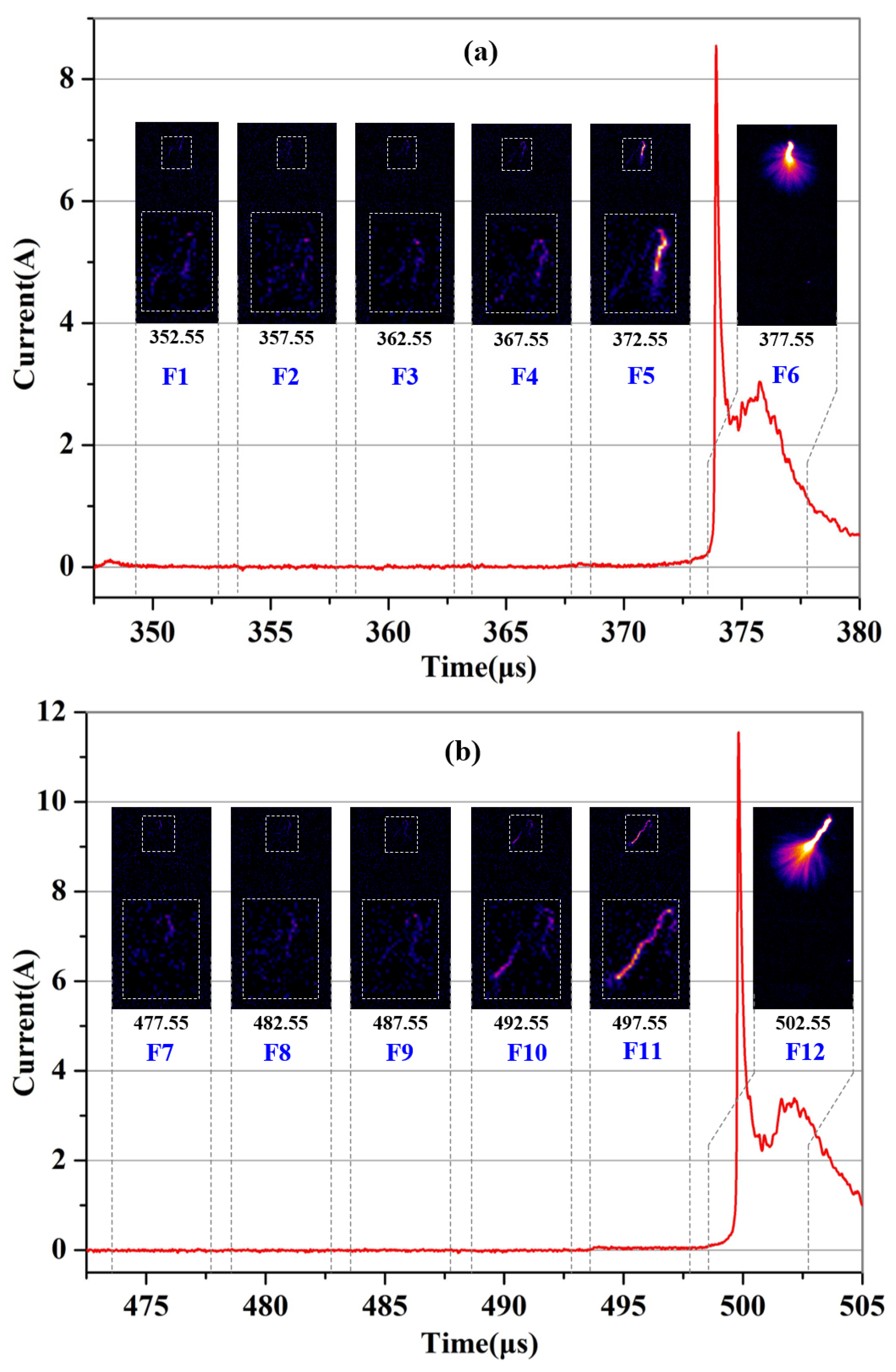
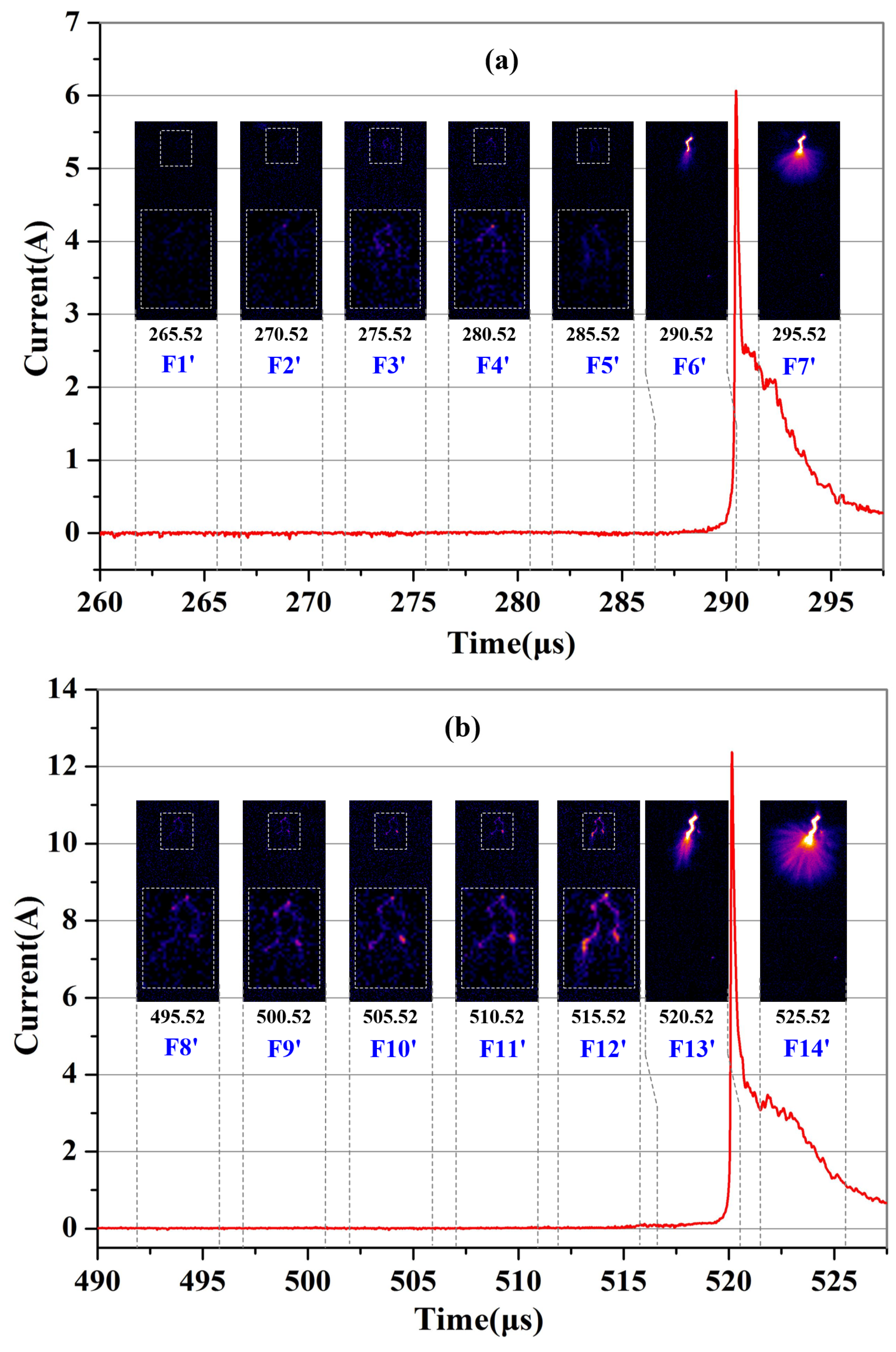
3.2. Gap Breakdown
4. Discussion
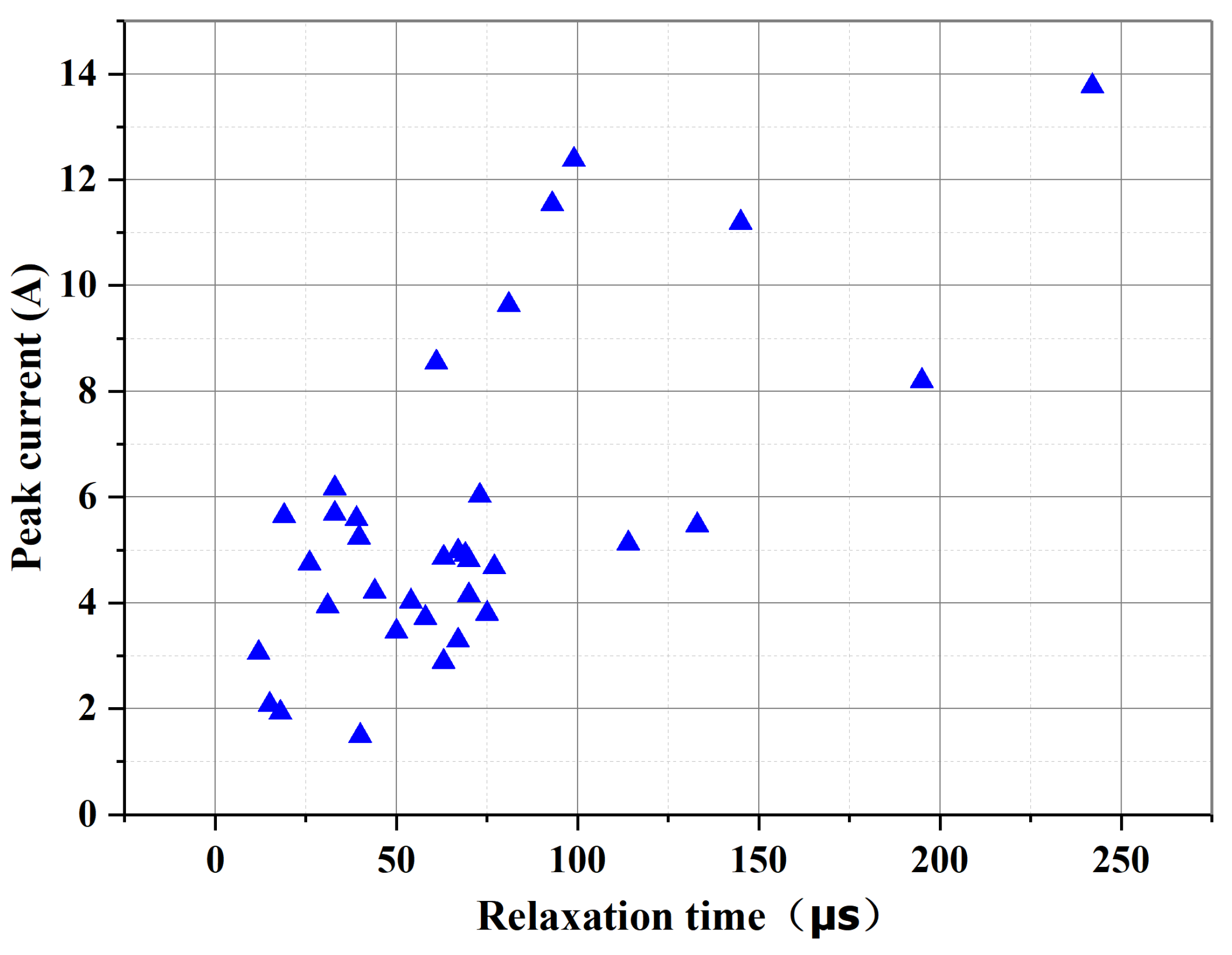
4.1. Relationship Between Restrike Current Pulse Peak and Relaxation Time
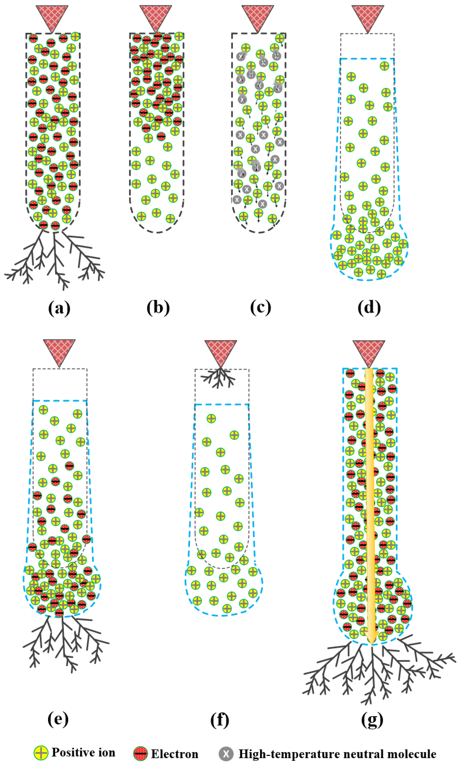
4.2. Luminescence of Leader Channel During Relaxation Process
5. Conclusions
Author Contributions
Funding
Institutional Review Board Statement
Informed Consent Statement
Data Availability Statement
Acknowledgments
Conflicts of Interest
References
- Goelian, N.; Lalande, P.; Bondiou-Clergerie, A.; Bacchiega, G.L.; Gazzani, A.; Gallimberti, I. A simplified model for the simulation of positive-spark development in long air gaps. J. Phys. D Appl. Phys. 1997, 30, 2441–2452. [Google Scholar] [CrossRef]
- Les Renardières Group. Research on long air gap discharges at Les Renardieres-1973 Results. Electra 1974, 35, 49–156. [Google Scholar]
- Gallimberti, I. The mechanism of the long spark formation. Le J. De Phys. Colloq. 1979, 40, 193–250. [Google Scholar] [CrossRef]
- Les Renardieres Group. Research on Long Air Gap Discharges at Les Renardieres. Electra 1972, 23, 53–157. [Google Scholar]
- Les Renardières Group. Positive Discharge in long air gaps at Les Renardieres-1975 results and conclusions. Electra 1977, 53, 31–151. [Google Scholar]
- Gallimberti, I.; Bacchiega, G.; Bondiou-Clergerie, A.; Lalande, P. Fundamental processes in long air gap discharges. Comptes Rendus-Phys. 2002, 3, 1335–1359. [Google Scholar] [CrossRef]
- Kostinskiy, A.Y.; Syssoev, V.S.; Bogatov, N.A.; Mareev, E.A.; Andreev, M.G.; Bulatov, M.U.; Sukharevsky, D.I.; Rakov, V.A. Abrupt Elongation (Stepping) of Negative and Positive Leaders Culminating in an Intense Corona Streamer Burst: Observations in Long Sparks and Implications for Lightning. J. Geophys. Res. Atmos. 2018, 123, 5360–5375. [Google Scholar] [CrossRef]
- Huang, S.; Chen, W.; Pei, Z.; Fu, Z.; Wang, L.; He, T.; Li, Z.; Gu, J.; Bian, K.; Xiang, N.; et al. The discharge preceding the intense reillumination in positive leader steps under the slow varying ambient electric field. Geophys. Res. Lett. 2020, 47, e2019GL086183. [Google Scholar] [CrossRef]
- Liao, Y.; Gao, C.; Li, R.; Wang, G. Long front time switching impulse tests of long air gap in UHV projects at altitude of 2100 m. IEEE Trans. Dielectr. Electr. Insul. 2014, 21, 982–987. [Google Scholar] [CrossRef]
- Chen, S.; Zeng, R.; Zhuang, C.; Zhou, X.; Ding, Y. Experimental Study on Branch and Diffuse Type of Streamers in Leader Restrike of Long Air Gap Discharge. Plasma Sci. Technol. 2016, 18, 305–310. [Google Scholar] [CrossRef]
- Zhou, X.; Chen, S.; Wang, H.; Zeng, R.; Zhuang, C.; Yu, J.; Ding, Y. Experiment on leader propagation characteristics of air gaps in UHVDC transmission towers under positive switching impulse voltages. CSEE J. Power Energy Syst. 2015, 1, 42–48. [Google Scholar] [CrossRef]
- Baldo, G.; Rea, M. An investigation of leader reillumination in long gaps. In Proceedings of the 11th International Conference on Phenomena in Ionized Gases, Prague, Czechoslovakia, 10–14 September 1973. [Google Scholar]
- Baldo, G.; Rea, M. Discussion of reilluminations. Electra 1974, 35, 96–100. [Google Scholar]
- Les Renardières Group. Double impulse tests of long airgaps Part 2: Leader decay and reactivation. IEE Proc. 1986, 133, 410–437. [Google Scholar]
- Domens, P.; Gibert, A.; Dupuy, J.; Hutzler, B. Propagation of the positive streamer-leader system in a 16.7 m rod-plane gap. J. Phys. D Appl. Phys 1991, 24, 1748–1757. [Google Scholar]
- Domens, P.; Gibert, A.; Dupuy, J.; Ruhling, F. Leader filament study near the anode in a rod plane gap. J. Phys. D Appl. Phys. 1991, 24, 1088–1097. [Google Scholar] [CrossRef]
- Yue, Y.; He, H.; Chen, W.; He, J.; Wu, C.; Zhao, X.; Huo, F. Characteristics of long air gap discharge current subjected to switching impulse. CSEE J. Power Energy Syst. 2015, 1, 49–58. [Google Scholar]
- Shah, W.A.; He, H.; He, J.; Yang, Y. Continuous and Discontinuous Streamer Leader Propagation Phenomena under Slow Front Impulse Voltages in a 10-meter Rod-Plane Air Gap. Energies 2018, 11, 2636. [Google Scholar] [CrossRef]
- Yang, Y.; He, J.; Zhao, X.; Xiao, P. Number of stems around the H.V. electrode in a 0.74-m air gap under positive impulse. Phys. Plasmas 2018, 25, 103513. [Google Scholar] [CrossRef]
- Yue, Y.; He, J. Digital time-resolved optical measurement of discharge currents in long air gaps. Rev. Sci. Instrum. 2013, 84, 85107. [Google Scholar] [CrossRef]
- Ryan, H.M. (Ed.) High Voltage Engineering and Testing; Institution of Engineering and Technology (IET): London, UK, 2001; pp. 555–573. [Google Scholar]
- Nijdam, S.; van de Wetering, F.M.J.H.; Blanc, R.; Veldhuizen, E.M.; Ebert, U. Probing photo-ionization: Experiments on positive streamers in pure gasses and mixtures. J. Phys. D Appl. Phys. 2010, 43, 145204–145219. [Google Scholar] [CrossRef]
- Liu, L.; Becerra, M. Gas heating dynamics during leader inception in long air gaps at atmospheric pressure. J. Phys. D Appl. Phys. 2017, 50, 345202. [Google Scholar] [CrossRef]
- Aleksandrov, N.L.; Bazelyan, É.M.; Konchakov, A.M. Plasma parameters in the channel of a long leader in air. Plasma Phys. Rep. 2001, 27, 875–885. [Google Scholar] [CrossRef]
- Popov, N.A. Formation and Development of a Leader Channel in Air. Plasma Phys. Rep. 2003, 29, 695–708. [Google Scholar] [CrossRef]
- Yang, Y. Research on the Characteristics and Mechanism of Positive Leader Restrike. Ph.D. Thesis, Huazhong University of Science and Technology, Wuhan, China, 2021. [Google Scholar]


Disclaimer/Publisher’s Note: The statements, opinions and data contained in all publications are solely those of the individual author(s) and contributor(s) and not of MDPI and/or the editor(s). MDPI and/or the editor(s) disclaim responsibility for any injury to people or property resulting from any ideas, methods, instructions or products referred to in the content. |
© 2025 by the authors. Licensee MDPI, Basel, Switzerland. This article is an open access article distributed under the terms and conditions of the Creative Commons Attribution (CC BY) license (https://creativecommons.org/licenses/by/4.0/).
Share and Cite
Yang, Y.; Liang, H.; Tan, A.; Liao, H.; Zhong, J. An Experimental Study on the Luminescence of the Leader Channel During the Relaxation Process Before Restrike in a Positive 6 m Air Gap Discharge. Appl. Sci. 2025, 15, 5348. https://doi.org/10.3390/app15105348
Yang Y, Liang H, Tan A, Liao H, Zhong J. An Experimental Study on the Luminescence of the Leader Channel During the Relaxation Process Before Restrike in a Positive 6 m Air Gap Discharge. Applied Sciences. 2025; 15(10):5348. https://doi.org/10.3390/app15105348
Chicago/Turabian StyleYang, Yongchao, Huijun Liang, Aiguo Tan, Honghua Liao, and Jianwei Zhong. 2025. "An Experimental Study on the Luminescence of the Leader Channel During the Relaxation Process Before Restrike in a Positive 6 m Air Gap Discharge" Applied Sciences 15, no. 10: 5348. https://doi.org/10.3390/app15105348
APA StyleYang, Y., Liang, H., Tan, A., Liao, H., & Zhong, J. (2025). An Experimental Study on the Luminescence of the Leader Channel During the Relaxation Process Before Restrike in a Positive 6 m Air Gap Discharge. Applied Sciences, 15(10), 5348. https://doi.org/10.3390/app15105348