Abstract
Integrated bearings, characterized by their unique structure, feature an inner ring that is seamlessly integrated with the shaft. This study is based on the theoretical framework of rolling bearing dynamics and considers bearing friction, lubrication, and Hertz elastic contact theory. A dynamic simulation model considering the interaction between the components of the rolling bearing is established. Additionally, a subroutine for calculating the interaction forces between the bearing components was written in C and compiled into a dynamic link library, which was then integrated with the dynamic simulation software. To solve and simulate the dynamics of the integrated bearing model, a sophisticated combination of a refined integration method and the predictor-corrector Adams–Bashforth–Moulton multistep technique was employed. The theoretical analysis offers insights into the vibration characteristics of the integrated bearings across different structural and operational parameters. Results indicate that a judicious selection of parameters, such as the curvature radius ratio of the inner and outer grooves and the gap of the cage pockets, can significantly enhance the bearings’ vibration and noise reduction capabilities. Furthermore, the application of an appropriate axial preload effectively reduces bearing vibrations, and there exists an optimal range of rotational speeds that minimizes these vibrations.
1. Dynamic Modeling of Integrated Bearing Systems
1.1. Specialized Structure of Integrated Bearings
In radar motors, rolling bearings are not only required to have a long service life but also to meet stringent vibration and noise criteria. The noise generated during bearing operation is a result of vibrations propagating as sound waves through the surrounding medium, thereby establishing vibration as the primary source of noise. The factors influencing bearing vibration are multifaceted, encompassing structural parameters, operating conditions, and lubrication, making the underlying mechanisms highly complex. Research on this specialized structure within the bearing field is limited. Therefore, it is crucial to undertake research on integrated bearings. Integrated bearings, which feature a unique design devoid of an inner ring, incorporate the inner race into the shaft itself. This configuration enables them to exhibit superior vibration and noise characteristics compared to conventional bearings. The structural and operating parameters of bearings are critical factors influencing their vibration characteristics. Researchers have also conducted studies on dynamic models of rolling bearings [1,2,3,4] and the influence of structural parameters on vibration [5,6].
About how bearing structural parameters affect bearing vibration, Tandon et al. [7] simulated local defects in the inner and outer raceways using rectangular, triangular, and half-sine functions with specified widths. They investigated the vibration responses of bearings under pure axial and pure radial load conditions. Wang Haifei et al. [8] examined how the radial clearance in rolling bearings affects the vibration of the aero-engine integrated system. Finite element methods were utilized to model both the bearing-rotor and casing systems. The study examined how radial clearance in bearings affects contact forces and overall vibrations under typical support conditions. Liu Yang et al. [9] created a dynamic model for a rotor system with deep-groove ball bearings, examining how bearing clearance and inner race acceleration influence the rotor systems’ dynamics. Yhland et al. [10] examined how radial and axial waviness in raceways, ball waviness, and uneven cage pocket hole distribution affect bearing-rotor system vibrations. Aktürk et al. [11] studied the effects of the number of balls and axial preload on bearing vibrations based on raceway control theory. The research indicates that appropriately applying axial preload and selecting the appropriate number of balls can effectively reduce bearing vibrations. Deng Sier et al. [12] proposed a dynamic model for deep-groove ball bearings that includes the surface waviness of bearing components. They analyzed the effects of various structural parameters, operating conditions, and harmonic parameters on bearing vibrations. Xu Minmin et al. [5] developed a nonlinear vibration model for bearings with six degrees of freedom, examining how clearance and load influence their vibration characteristics. Shah et al. [13] performed a theoretical and experimental analysis on how radial load affects the vibration amplitude of deep-groove ball bearings under oil lubrication. Xu Hongyang et al. [14] developed a dynamic model for a bearing-rotor system with inner race misalignment, examining how misalignment angle, radial clearance, and rotational speed influence system dynamics. Jia Xiaofang et al. [15] developed nonlinear dynamic equations for a deep groove ball bearing featuring a crowned cage. A variable step size predictor-corrector method was used to solve the equations, and the impact of rotational speed on bearing vibrations was analyzed. Wang Pengfei et al. [16] established a dynamic model of the deep-groove ball bearing-rotor system to investigate the effects of radial load and bearing clearance on the vibration characteristics of the system, considering misalignment in the bearings.
About the establishment of bearing dynamics modeling, Li Yamin et al. [17] proposed a coupled dynamic model of the rolling bearing-rotor system, seamlessly integrating the rotor’s detailed finite element model with the bearing dynamic model. They also introduced a variable-step numerical integration algorithm for solving the system. Li Fanjie et al. [18] considered the effects of sliding and developed a dynamic model of the DGB 6205 bearing, which incorporates the radial motion of the inner race, the rotation of the cage, and the rotation of the balls. They investigated the impact of time-varying loads on the vibration characteristics of the bearing system. Xu Lixin et al. [19] proposed a dynamic modeling method for deep-groove ball bearings with waviness defects. Wang Zhe et al. [20] considered outer race defects and inner race misalignment, proposing a transient displacement excitation model based on piecewise functions. They solved this model to obtain the vibration response of the bearing. The study by Ashtekar, A. et al. [21] investigated the impact of raceway defects on the motion of deep-groove ball bearings using a six-degrees-of-freedom dynamic model. Shah et al. [22] developed a dynamic model to predict the vibrations of deep-groove ball bearings, taking into account the masses of the shaft, raceway, balls, and bearing housing. Weinzapfel, N. et al. [23] established a dynamic model for deep-groove ball bearings that incorporates a flexible cage, analyzing the impact of cage flexibility on the bearings’ dynamics. Sopanen, J. et al. [24,25] proposed a six-degrees-of-freedom dynamic model for deep-groove ball bearings that considers both distributed and localized defects. The study examined the effects of clearance on the natural frequencies and vibrations of the bearing system.
The current research predominantly addresses conventional ball bearings, leaving a significant gap in the study of integrated bearings with distinct structural features. Addressing this gap, the study develops a dynamic model for integrated bearings through the dynamic analysis of integrated bearings. This study seeks to clarify the vibrational properties of integrated bearings and examine how structural parameters influence vibration behavior. The findings will provide a theoretical foundation for the selection of structural parameters in integrated bearings.
Integrated bearings consist of a spindle, outer ring, cage, and balls. Their design and analysis methods differ significantly from deep-groove ball bearings due to the lack of an inner ring structure. Unlike conventional deep-groove ball bearings, integrated bearings directly machine the inner raceway onto the spindle, resulting in a smaller center diameter, higher rotational speeds, and reduced installation errors, thereby offering improved precision and dynamic performance.
Since integrated bearings combine the inner ring with the spindle, analyses must consider the characteristics of both components. It is essential to account for the interaction between the balls and the spindle while also analyzing the external environment in contact with the spindle. To facilitate research, the interaction with the external environment can be transformed into constraints on the degrees of freedom of the spindle.
1.2. Coordinate System of Integrated Bearings
To facilitate the description of the motion of the various components of integrated bearings, a coordinate system for the integrated bearing is established, as shown in Figure 1.
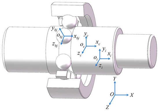
Figure 1.
Integrated bearing coordinate system.
(1) Inertial Coordinate System : This system is fixed in space, with its origin coinciding with the center of the inner raceway of the integrated bearing. The X-axis aligns with the bearing’s axis, and the plane passes through the center of the inner raceway, remaining parallel to the bearing’s radial plane.
(2) Spindle Coordinate System : The origin of this system coincides with the centroid of the spindle. The axis aligns with the spindle’s rotational axis, and the plane passes through the spindle’s centroid, coinciding with the spindle’s radial plane.
(3) Cage Coordinate System : The origin is located at the center of the pocket in the cage. The axis aligns with the cage’s rotational axis, and the plane passes through the center of the pocket, coinciding with the cage’s radial plane.
(4) Center Coordinate System of the ()-th Ball : The origin coincides with the center of the ()-th ball. The axis is directed radially with respect to the bearing and is perpendicular to the surface of the ball. The axis aligns with the circumferential direction of the ball, and the orientation of axes is determined using the right-hand rule. This coordinate system is fixed to the center of the ()-th ball and moves with the ball throughout its motion. Each ball possesses its own local coordinate system.
1.3. Dynamical Differential Equations of Balls
Figure 2 illustrates the force exerted on the ball during the integrated bearing’s operation. In the figure, subscripts () and () denote the inner and outer raceways. The subscript () denotes the ()-th ball. The subscripts () and () denote the ball and the cage, respectively. The angles () and () denote the contact angles between the inner and outer raceways and the ball. The forces () and () denote the contact forces between the inner and outer raceways and the ball. The forces (), (), (), and () denote the drag forces acting between the inner and outer raceways and the ball. The forces () and () represent the inertial force components of the ball. The forces () and () indicate the rolling friction at the contact points between the cage and the ball, whereas () and () represent the sliding friction at these contact points. The forces (), (), (), and () denote the horizontal components of fluid dynamic pressures exerted on the ball. Meanwhile, (), (), (), and () denote the fluid dynamic pressure friction forces in the contact zone between the raceways and the ball. The force () represents the weight of the ball. The forces () and () are the projections of the contact forces between the cage and the ball within the ball’s coordinate system. The angle () represents the position angle of the ball, while () denotes the angle between forces () and ().The angle () represents the angle between () and (), while () denotes the distance from the contact point of the cage pocket to the ball along the direction of (). The quantities (), (), and () represent the moments of inertia of the ball about the three axes in its coordinate system. The quantities () and () represent the inertial moments of the ball in the () and () directions, respectively. The force () represents the resistance exerted by the oil–gas mixture on the ball. The quantities (), (), and () represent the angular velocity components of the ball in its coordinate system, while (), (), and () denote the angular acceleration components of the ball in the same coordinate system. Establish a unified set of differential equations for the dynamics of bearing balls.
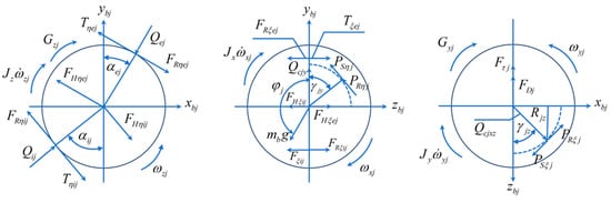
Figure 2.
Force diagram of the ball.
In the equation, () represents the mass of the ball; (), (), and () denote the accelerations at the center of mass of the ball; and () indicates the moment of inertia of the ball. Additionally, (), (), and () are the components of angular velocity, while (), (), and () are the components of angular acceleration. Lastly, () signifies the translational velocity of the ball, and () represents its diameter.
1.4. Dynamical Differential Equations of Cage
The integrated bearing cage is a crown-shaped cage. During the operation of the bearing, the relative positions of the steel balls and the pockets of the cage are quite complex. Therefore, a diagram illustrating the relative positional relationships has been established, as shown in Figure 3. Point () represents the contact point between the steel ball and the pocket, while (), (), and () are the projections of the contact points between the steel ball and the cage, as well as the distance to the center of mass of the cage in the cage coordinate system. A set of dynamic differential equations for the cage has been established, as follows:
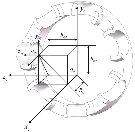
Figure 3.
Schematic diagram of the position of the ball.
In the equation, () represents the mass of the cage; (), (), and () denote the acceleration of the cage’s center of mass; (), (), and () indicate the moment of inertia of the cage; (), (), and () refer to the components of the cage’s angular velocity; (), (), and () signify the components of the cage’s angular acceleration; () represents the number of steel balls; and () is the axial distance between the center plane of the cage’s holes and the position of the cage’s center of mass.
1.5. Dynamical Differential Equations of Spindle
During the operation of the integrated bearing, the displacement degree of freedom of the spindle in the () direction, as well as the rotational degrees of freedom in the () and () directions, are constrained by external factors. The spindle is subjected to the combined effects of the steel balls and external loads. The differential equations governing the core shaft are as follows:
In the equations, () and () represent the accelerations of the core shaft’s center of mass, while () and () denote the axial and radial forces exerted on the bearing.
1.6. Solution Process of the System of Dynamical Differential Equations
Using the multibody dynamics software Adams (Student) as the development platform, a program was written in C language to solve the integrated bearing dynamics differential equations, and a dynamic link library was generated. A parametric simulation analysis model for the integrated bearing was then created. The integrated bearing dynamics differential equations were solved using the predicted and corrected Gear’s stiff variable-step integration algorithm, and the solution process is shown in Figure 4.
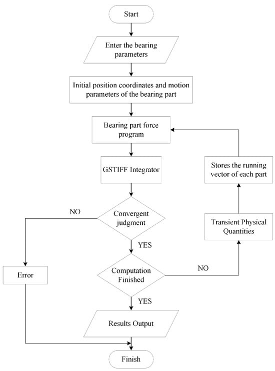
Figure 4.
Solution process flowchart.
2. Integrated Bearing Dynamic Performance Analysis
The dynamic differential equations of integrated ball bearings have strong nonlinearity and are complex to solve. In this paper, the fine integration method is combined with the Adams–Bashforth–Moulton multi-step method to integrally solve the nonlinear dynamic equation of the integrated ball bearing, and the magnitude of the radial in-plane vibration and the axial in-plane vibration of the bearing mandrel are obtained. Taking a certain type of integrated ball bearing as an example, the relationship between the bearing structure, working conditions, and mandrel flexibility and the vibration characteristics of the integrated ball bearing was analyzed. The integrated bearing in this model uses grease lubrication, which results in a relatively small fluid dynamic pressure friction. Therefore, its impact is neglected in the calculations presented in this paper.
The structural parameters of the bearing are presented in Table 1. The materials for the outer ring, core shaft, and steel balls are GCr15, while the cage material is PA46. Specific parameters can be found in Table 2 and Table 3.

Table 1.
Structural parameters of the integrated bearing.
Table 2.
Material properties of GCr15.
Table 3.
Material properties of PA46.
2.1. Results of the Integrated Bearing Dynamics Model
The bearing operates at ambient temperature, with all contact surfaces of the components assumed to be ideal circles. The spindle rotates at a speed of 50,000 r/min. The radial force in the Y-direction within the radial plane is 200 N, while the radial force in the Z-direction is 0 N, and the axial force (in the X-direction) is also 0 N. The cage pocket clearance is 0.051 mm, and the curvature radius coefficients for both the inner and outer raceways are 0.529. After solving the model, the vibration velocity of the spindle’s center of mass in the radial direction over time is obtained, as shown in Figure 5 and Figure 6.
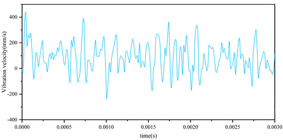
Figure 5.
Vibration velocity of the spindle’s center of mass in the Y-direction.
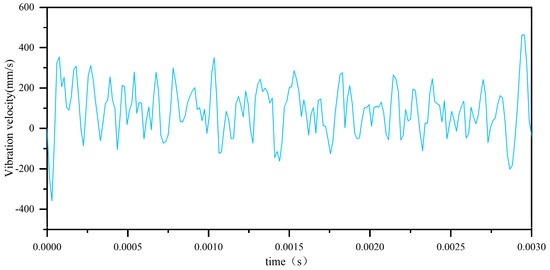
Figure 6.
Vibration velocity of the spindle’s center of mass in the Z-direction.
As shown in Figure 7 and Figure 8, the variation of the radial vibration acceleration at the center of mass of the spindle over time is obtained after solving the model. The effective value is calculated, and using Equation (15), the vibration acceleration level is determined.
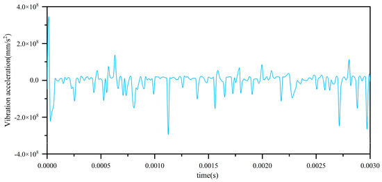
Figure 7.
Vibration acceleration of the spindle’s center of mass in the Y-direction.
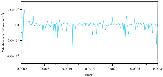
Figure 8.
Vibration acceleration of the spindle’s center of mass in the Z-direction.
In the equation, () represents the standard reference value for vibration, which is typically taken as m/s2.
The frequency domain spectrum is shown in Figure 9. The main frequency components are 833 Hz(fr), 1666 Hz(2fr), 2333 Hz(fr + 0.5fi), and 3800 Hz(fi). Among them, fr represents the rotational frequency, and fi represents the bearing passing frequency. In general, the main frequency components in the spectrum are the frequency conversion, bearing passing frequency and their combined frequency. The bearing passing frequency calculation formula is shown in Equation (16).
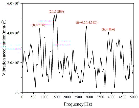
Figure 9.
Frequency diagram of vibration acceleration of integrated bearing.
Here, (z) represents the number of rolling elements, (f) is the bearing rotational frequency, (d) is the diameter of the bearing balls, and (D) is the pitch diameter of the bearing.
2.2. Influence of Structural Parameters on Vibration in Integrated Bearings
The structural parameters of integrated bearings significantly influence their vibration characteristics. To investigate the specific effects of these parameters, this section examines the impact of the curvature radius coefficients of the inner and outer raceways, as well as the cage pocket clearance, on the vibration characteristics of integrated bearings. The analysis is conducted at a spindle speed of 50,000 rpm, with a radial force of 200 N in the Y-direction and no radial force in the Z-direction or axial force in the X-direction. The results focus on the radial vibration acceleration level and vibration velocity at the center of mass of the bearing spindle to describe the overall vibration levels of the bearing.
2.2.1. Influence of Inner Groove Curvature Radius Coefficients on Vibration Value
When the outer groove curvature radius coefficient is set at 0.529 and the cage pocket clearance is 0.051 mm, the relationship between the inner raceway curvature radius coefficient and bearing vibration in integrated bearings is shown in Figure 10. As shown in the figure, with an increase in the inner raceway curvature radius coefficient, both the vibration acceleration level and vibration velocity of the integrated bearings initially decrease and then increase. The optimal vibration characteristics are observed when the inner raceway curvature radius coefficient is in the range of 0.52 to 0.53.
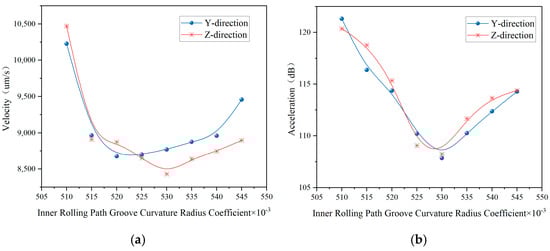
Figure 10.
Trend of vibration with variation in the curvature radius coefficient of the inner rolling path. (a) Trends in vibration velocity variation. (b) Trends in vibration acceleration variation.
2.2.2. Influence of Outer Groove Curvature Radius Coefficients on Vibration Value
When the inner groove curvature radius coefficient is set at 0.529 and the cage pocket clearance is 0.051 mm, the relationship between the outer raceway curvature radius coefficient and bearing vibration in integrated bearings is presented in Figure 11. As illustrated in the figure, with an increase in the outer raceway curvature radius coefficient, both the vibration acceleration level and vibration velocity of the integrated bearings initially decrease and then increase. The optimal vibration characteristics are observed when the outer raceway curvature radius coefficient is in the range of 0.52 to 0.53.
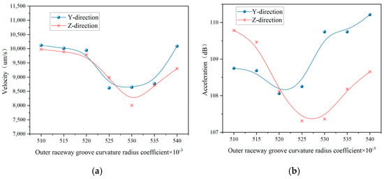
Figure 11.
Trend of vibration with variation in the curvature radius coefficient of the outer rolling path. (a) Trends in vibration velocity variation. (b) Trends in vibration acceleration variation.
2.2.3. Effect of Cage Pocket Clearance on Vibration of Integrated Bearings
Cage pocket clearance significantly impacts the vibration characteristics of integrated bearings. The integrated bearings referenced in this study utilize a crowned cage made of nylon material. Figure 12 illustrates the relationship between cage pocket clearance and bearing vibration when both the inner and outer raceway curvature radius coefficients are set at 0.529. As shown, for the crowned cage, an increase in cage pocket clearance initially leads to a decrease in the vibration acceleration level and vibration velocity of the integrated bearings, followed by an increase. The optimal vibration characteristics are observed when the cage pocket clearance is between 0.045 and 0.055 mm.
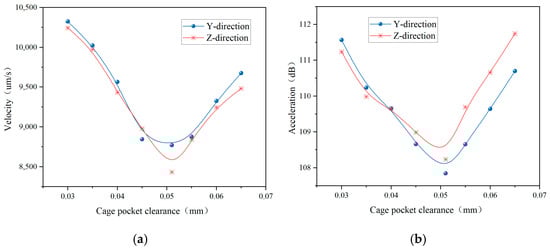
Figure 12.
Trend of vibration with variation in the cage pocket clearance. (a) Trends in vibration velocity variation. (b) Trends in vibration acceleration variation.
2.3. Impact of Operating Conditions on Vibration of Integrated Bearings
The operating conditions of integrated bearings directly influence their vibration characteristics during operation. To investigate the specific effects of these conditions on the vibration characteristics of integrated bearings, this section examines the impacts of varying rotational speeds, radial forces, and axial preload on the vibration performance. The study considers an integrated ball bearing with a rotating inner shaft and a fixed outer ring, with both the inner and outer raceway curvature radius coefficients set at 0.529 and a cage pocket clearance of 0.051 mm. The analysis focuses on the radial vibration acceleration level and vibration velocity at the centroid of the bearing shaft to characterize the impact of changes in operating conditions on bearing vibration.
2.3.1. Impact of Axial Preload on the Vibration of Integrated Bearings
Under the operating conditions of a shaft speed of 50,000 r/min, a radial load of 200 N in the Y-direction, and a radial load of 0 N in the Z-direction, the relationship between axial preload and bearing vibration is illustrated in Figure 13. As shown, applying a certain level of axial preload to the integrated bearing effectively reduces its vibration. Furthermore, with increasing axial preload, the bearing vibration initially decreases and then begins to increase. The optimal vibration characteristics of the integrated bearing occur when the ratio of axial preload to the bearing’s rated dynamic load is between 0.5% and 0.8%.
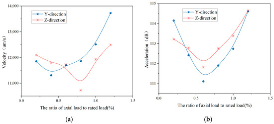
Figure 13.
Trend of vibration with variation in the axial preload. (a) Trends in vibration velocity variation. (b) Trends in vibration acceleration variation.
2.3.2. Impact of Radial Load on the Vibration of Integrated Bearings
Under the operating conditions of a shaft speed of 50,000 r/min and an axial load of 0 N, the relationship between the radial load in the Y-direction and bearing vibration is illustrated in Figure 14. As shown, with the gradual increase in the working load of the integrated bearing, both the vibration velocity and vibration acceleration level tend to increase progressively. Selecting an appropriate radial load can effectively reduce bearing vibration.
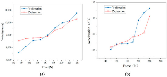
Figure 14.
Trend of vibration with variation in the radial load. (a) Trends in vibration velocity variation. (b) Trends in vibration acceleration variation.
2.3.3. Impact of Bearing Speed on the Vibration of Integrated Bearings
Under the operating conditions of a radial load of 200 N in the Y-direction, a radial load of 0 N in the Z-direction, and an axial load of 0 N, the relationship between the speed of the integrated bearing and its vibration is illustrated in Figure 15. As shown, with the gradual increase in the operating speed of the integrated bearing, both the vibration velocity and vibration acceleration levels tend to increase progressively. Therefore, selecting an appropriate operating speed can effectively reduce bearing vibration.
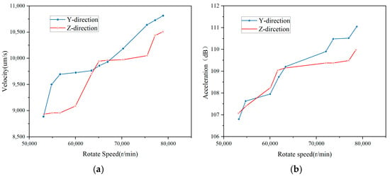
Figure 15.
Trend of vibration with variation in the bearing speed. (a) Trends in vibration velocity variation. (b) Trends in vibration acceleration variation.
2.4. Comparison Between Integrated Bearings and Deep-Groove Ball Bearings
Under the same operating conditions (such as rotational speed, load, etc.), the vibration characteristics of integrated bearings and deep-groove ball bearings with similar structural dimensions were compared. As shown in Figure 16, the trends of vibration velocity and vibration acceleration level with respect to speed are almost identical for both integrated bearings and deep-groove ball bearings. However, the vibration acceleration level of the integrated bearing is slightly lower than that of the deep-groove ball bearing. This indicates that under the same operating conditions, the vibration characteristics of the integrated bearing and the deep-groove ball bearing are generally similar, with the integrated bearing having a more compact structure, making it suitable for more confined working environments.
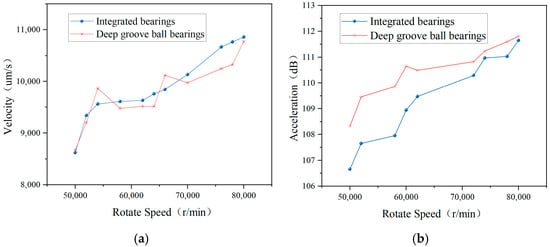
Figure 16.
Comparison between integrated bearings and deep groove ball bearings. (a) Trends in vibration velocity variation. (b) Trends in vibration acceleration variation.
The structural parameters of the deep-groove ball bearing are presented in Table 4.
Table 4.
Structural parameters of the deep groove ball bearing.
2.5. Calculation Result Verification
The maximum contact force between the integrated bearing cage and the rolling balls was calculated using the finite element analysis software (Ansys2016). As shown in Figure 17, the results of the finite element method are compared with the dynamics simulation software. The finite element model of the integrated bearing was established, with a total of 204,251 finite elements. The operational parameters (such as rotational speed and load) are consistent with those in the previous section.
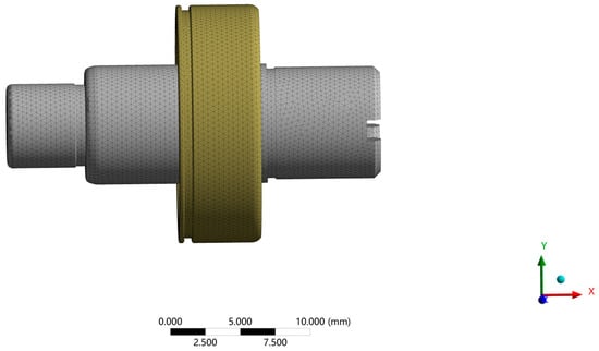
Figure 17.
Finite element model of integrated bearing.
A comparison of the two calculation methods is presented in Figure 18. The results are in close agreement, with a maximum error of approximately 13%, thus validating the accuracy of the model developed in this paper.
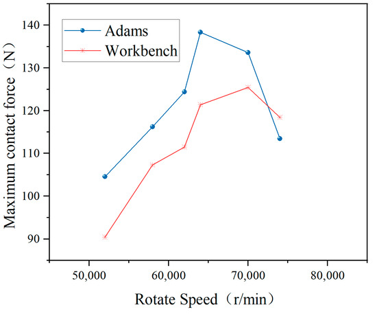
Figure 18.
Comparison of finite element and dynamic calculations.
3. Conclusions
A dynamic model for an integrated bearing that employs a structure with an inner ring and shaft integration was established. The vibration characteristics of the integrated bearing were analyzed, focusing on the influence of various structural parameters, such as cage pocket clearance and the curvature radius coefficients of the inner and outer raceways, alongside operational parameters, including axial preload, rotational speed, and radial load. A comparative analysis between the integrated bearing and the deep-groove ball bearing was also conducted. The results indicate that, under the same vibration characteristic requirements, the integrated bearing features a more compact structure and is capable of adapting to a wider range of operating conditions. Finally, the model in this paper was validated through finite element analysis. The results show that the maximum error is approximately 13%, which confirms the accuracy of the model.
(1) Our findings indicate that a careful selection of structural parameters can significantly reduce vibration in the design of the integrated bearing. By optimizing the curvature radius coefficients for both the inner and outer raceways, as well as the cage pocket clearances, the vibration levels can be substantially diminished. The optimal curvature radius coefficients for the inner and outer raceways range from 0.52 to 0.53, and the cage pocket clearance is between 0.045 and 0.055 mm.
(2) Furthermore, our results demonstrate that the application of an appropriate axial preload effectively reduces the vibration of the integrated bearing. Conversely, an increase in rotational speed correlates with a progressive escalation in vibration levels. Similarly, higher radial loads are associated with increased vibration acceleration. Therefore, selecting appropriate operating parameters for the integrated bearing, such as rotational speed and load, can ensure its stable operation.
Author Contributions
Conceptualization, C.Z. and J.Z.; methodology, C.Z.; software, C.Z.; validation, C.Z., N.L. and B.W.; formal analysis, C.Z.; investigation, J.Z.; resources, J.Z., B.W. and N.L.; data curation, C.Z.; writing—original draft preparation, C.Z.; writing—review and editing, J.Z. and N.L.; visualization, C.Z.; supervision, J.Z.; project administration, J.Z.; funding acquisition, J.Z. All authors have read and agreed to the published version of the manuscript.
Funding
This work was financially supported by the Key research and development program of Ningbo (2022Z050). The APC was funded by Dalian University of Technology.
Institutional Review Board Statement
Not applicable.
Informed Consent Statement
Not applicable.
Data Availability Statement
The original contributions presented in this study are included in the article. Further inquiries can be directed to the corresponding author.
Conflicts of Interest
The authors declare no conflict of interest.
References
- Ambrozkiewicz, B.; Litak, G.; Georgiadis, A.; Meier, N.; Gassner, A. Analysis of Dynamic Response of a Two Degrees of Freedom (2-DOF) Ball Bearing Nonlinear Model. Appl. Sci. 2021, 11, 787. [Google Scholar] [CrossRef]
- Lin, S.; Sun, J.; Zhao, C.; Peng, Y. Research on Dynamic Characteristics of the RBBH System Based on Dynamics Model and Vibration Data Fusion-Web of Science Core Collection. Sensors 2022, 22, 3806. [Google Scholar] [CrossRef] [PubMed]
- Mao, Y.; Wang, L.; Zhang, C. Study on the Load Distribution and Dynamic Characteristics of a Thin-Walled Integrated Squirrel-Cage Supporting Roller Bearing. Appl. Sci. 2016, 6, 415. [Google Scholar] [CrossRef]
- Questa, H.; Mohammadpour, M.; Theodossiades, S.; Garner, C.P.; Bewsher, S.R.; Offner, G. Tribodynamic Modelling of High-Speed Rolling Element Bearings in Flexible Multi-Body Environments. Machines 2023, 11, 93. [Google Scholar] [CrossRef]
- Xu, M.; Feng, G.; He, Q.; Gu, F.; Ball, A. Vibration Characteristics of Rolling Element Bearings with Different Radial Clearances for Condition Monitoring of Wind Turbine. Appl. Sci. 2020, 10, 4731. [Google Scholar] [CrossRef]
- Ambrozkiewicz, B.; Syta, A.; Georgiadis, A.; Gassner, A.; Meier, N. Experimental Verification of the Impact of Radial Internal Clearance on a Bearing’s Dynamics. Sensors 2022, 22, 6366. [Google Scholar] [CrossRef]
- Tandon, N.; Choudhury, A. An Analytical Model for the Prediction of The Vibration Response of Rolling Element Bearings Due to a Localized Defect. J. Sound Vib. 1997, 205, 275–292. [Google Scholar] [CrossRef]
- Wang, H.; Gong, J.; Chen, G. Characteristics analysis of aero-engine whole vibration response with rolling bearing radial clearance. J. Mech. Sci. Technol. 2017, 31, 2129–2141. [Google Scholar] [CrossRef]
- Liu, Y.; Han, J.; Zhao, S.; Meng, Q.; Shi, T.; Ma, H. Study on the Dynamic Problems of Double-Disk Rotor System Supported by Deep Groove Ball Bearing. Shock Vib. 2019, 2019, 8120569. [Google Scholar] [CrossRef]
- Yhland, E.M. Paper 29: Waviness Measurement-An Instrument for Quality Control in Rolling Bearing Industry. Arch. Proc. Inst. Mech. Eng. Conf. Proc. 1967, 182, 438–445. [Google Scholar] [CrossRef]
- Akturk, N.; Uneeb, M.; Gohar, R. The Effects of Number of Balls and Preload on Vibrations Associated with Ball Bearings. J. Tribology 1997, 119, 747–753. [Google Scholar] [CrossRef]
- Deng, S.-E.; Sun, C.-Y.; Gu, J.-F.; Cui, Y.-C. Vibration characteristics of low-noise deep groove ball bearings. J. Vib. Shock 2015, 34, 12–19. [Google Scholar]
- Shah, D.S.; Patel, V.N. Theoretical and experimental vibration studies of lubricated deep groove ball bearings having surface waviness on its races. Measurement. 2018, 129, 405–423. [Google Scholar] [CrossRef]
- Xu, H.; Yang, Y.; Ma, H.; Luo, Z.; Li, X.; Han, Q.; Wen, B. Vibration characteristics of bearing-rotor systems with inner ring dynamic misalignment. Int. J. Mech. Sci. 2022, 230, 107536. [Google Scholar] [CrossRef]
- Jia, X.; Deng, K.; Tang, Z.; Cui, Y.; Zhang, W.; Deng, S. A study on vibration characteristics of crown cages in high speed ball bearings. Zhendong Yu Chongji. J. Vib. Shock 2022, 41, 16–23+30. [Google Scholar]
- Wang, P.; Yang, Y.; Ma, H.; Xu, H.; Li, X.; Luo, Z.; Wen, B. Vibration characteristics of rotor-bearing system with angular misalignment and cage fracture: Simulation and experiment. Mech. Syst. Signal Proc. 2023, 182, 109545. [Google Scholar] [CrossRef]
- Li, Y.; Cao, H.; Tang, K. A general dynamic model coupled with EFEM and DBM of rolling bearing-rotor system. Mech. Syst. Signal Proc. 2019, 134, 106322. [Google Scholar] [CrossRef]
- Li, F.; Li, X.; Shang, D. Dynamic Modeling and Vibration Characteristics Analysis of Deep-Groove Ball Bearing, Considering Sliding Effect. Mathematics 2021, 9, 2408. [Google Scholar] [CrossRef]
- Xu, L.; Li, Y. Modeling of a deep-groove ball bearing with waviness defects in planar multibody system. Multibody Syst. Dyn. 2015, 33, 229–258. [Google Scholar] [CrossRef]
- Wang, Z.; Li, G.; Zhou, X.; Zhang, H.; Lin, Z.; Jia, S. Dynamic analysis of deep groove ball bearing with localized defects and misalignment. J. Sound Vibr. 2024, 568, 118071. [Google Scholar] [CrossRef]
- Ashtekar, A.; Sadeghi, F.; Stacke, L.-E. Surface defects effects on bearing dynamics. Proc. Inst. Mech. Eng. Part J J. Eng. Tribol. 2010, 224, 25–35. [Google Scholar] [CrossRef]
- Shah, D.S.; Patel, V.N. A dynamic model for vibration studies of dry and lubricated deep groove ball bearings considering local defects on races. Measurement 2019, 137, 535–555. [Google Scholar] [CrossRef]
- Weinzapfel, N.; Sadeghi, F. A Discrete Element Approach for Modeling Cage Flexibility in Ball Bearing Dynamics Simulations. J. Tribol. Trans. ASME 2009, 131, 021102. [Google Scholar] [CrossRef]
- Sopanen, J.; Mikkola, A. Dynamic model of a deep-groove ball bearing including localized and distributed defects. Part 2: Implementation and results. Proc. Inst. Mech. Eng. Pt. K J. Multi-Body Dyn. 2003, 217, 213–223. [Google Scholar] [CrossRef]
- Sopanen, J.; Mikkola, A. Dynamic model of a deep-groove ball bearing including localized and distributed defects. Part 1: Theory. Proc. Inst. Mech. Eng. Pt. K J. Multi-Body Dyn. 2003, 217, 201–211. [Google Scholar] [CrossRef]
Disclaimer/Publisher’s Note: The statements, opinions and data contained in all publications are solely those of the individual author(s) and contributor(s) and not of MDPI and/or the editor(s). MDPI and/or the editor(s) disclaim responsibility for any injury to people or property resulting from any ideas, methods, instructions or products referred to in the content. |
© 2024 by the authors. Licensee MDPI, Basel, Switzerland. This article is an open access article distributed under the terms and conditions of the Creative Commons Attribution (CC BY) license (https://creativecommons.org/licenses/by/4.0/).