1. Introduction and Literature Review
Various techniques have been developed and implemented to design conformal cooling channels in complex geometries to achieve the desired cooling throughout the cast [
1]. However, there are still challenges in cooling small or thin intrusions within the mould, particularly at sharp corners. Internal corners of the cast are especially difficult to cool uniformly due to their relatively large volume and limited surface area available for cooling, as compared to the two sides of the corner. Consequently, internal corners suffer from higher temperatures due to the restricted surface area exposed to cooling channels [
2], while external corners often experience overcooling [
3]. The insufficient cooling in internal corners results in delayed solidification, increasing the risk of crack formation due to tension stresses induced by the contraction of adjacent solidified sections [
4,
5]. Additionally, soldering defects commonly occur in these areas due to the presence of hot spots [
6].
The issue can be addressed by employing smaller cooling channels or positioning the channels closer to the mould/cast surface. However, producing smaller channels is associated with an increase in pressure drop, as well as limitations imposed by the 3D printing process. Additionally, minor contamination on the surfaces of small channels can significantly alter their dimensions, affecting coolant flow rate, heat transfer efficiency, and distribution unless multiple, precisely controlled separate cooling channels are used. Another approach to enhance cooling at specific locations is to position the channels closer to the cast cavity. This method, however, is limited by the substantial increase in dynamic thermal stresses, which can adversely affect the service life of the mould.
Several methods have been developed to address localised cooling within the tool. One approach involves using bubblers [
7], a commonly employed technique for targeting specific regions in the mould. However, accessing the target regions can be challenging in some cases, and bubblers usually also cool all the areas surrounding its location and may lead to overcooling areas that are already sufficiently cooled. Another technique involves inserting a more conductive material between the regions requiring enhanced cooling and the cooling channels [
8,
9]. This method, while promising, faces technical limitations such as mismatched thermal expansion and the complexity of fabricating two materials without defects. A further proposed solution is the incorporation of internal fins or lattice structures within the cooling channels to improve cooling in specific regions [
10,
11]. This approach increases the surface area in contact with the coolant. Although integrating fins or lattice structures during the 3D printing process can be achieved without significant additional cost, it necessitates larger channel sizes and may not be practical for small cooling channels due to reduced fluid flow cross-section and potential for partial blockage over extended operation periods.
Local overheating is a well-recognized issue in die casting. However, overcooling in certain regions within the die or cavity can also lead to casting defects [
12]. Overcooling typically occurs when casting thin sections with complex geometries, such as fins, or when attempting to use bubblers or cooling channels to target specific areas in an intrusion section. In many cases, the sides of these intrusions can become overcooled. Similarly, internal corners may experience excessive cooling on their sides. The overheated section in the mould cavity can be controlled to some extent through external cooling sprays, which can be directed to these specific locations to achieve optimal die temperatures, generally ranging from approximately 150 °C to 320 °C, to ensure high-quality casting [
13]. However, excessive cooling of the die surface can lead to severe thermal shocks upon contact with molten metal. This can cause early solidification of the flowing metal, potentially leading to incomplete filling of the die cavity. Additionally, residual humidity from incomplete evaporation of water in the cooling lubricant can result in porosity in the casting.
Utilising noncircular and nonuniform cross-sectional profiles in conformal cooling channels can enhance cooling uniformity at corners [
14], though this approach may not be effective for cooling small features. The design of internal cooling channels with nonuniform cross-sections is related to the study of surface sensitivity response [
3]. In a previous study [
15], the design of conformal cooling channels for cooling corners using the adjoint optimisation method demonstrated that the standard deviation of temperature variation on the mould cavity surface could be reduced from 19 °C to 6 °C for internal corners and from 26 °C to 2 °C for external corners. This method employs mesh deformation to adjust the positions of mesh nodes within the cooling channel, resulting in changes to the channel’s surface location and cross-sectional shape. These modifications are made to optimise an objective function, which is defined as the minimisation of the standard deviation of the temperature on the mould cavity surface. However, this method involves extensive computational time to iteratively adjust the cooling channels’ location and cross-sectional shape to achieve the desired objective function. Consequently, for complex geometries with multiple corners, this approach may be impractical.
In this study, three lattice structures previously tested by [
15] were utilised to surround the cooling channels on either side of a 90°-angled cast section in order to limit heat transfer and increase the thermal resistance. A three-dimensional thermal model was subsequently developed to evaluate the contribution of these lattice structures to achieving uniform cooling of the 90° section corner. This method can be integrated with existing techniques to improve cooling efficiency at corner regions. Additionally, lattice structures can be incorporated into any location within a 3D-printed insert or tool to reduce heat transfer in specific areas. Lattice structures have also been recommended for use in high-pressure die casting tools to reduce weight [
16].
2. Computation Domain Description
The heat transfer process in high-pressure die casting is complex, unsteady, and involves phase change. However, for this study, cycle-specific details are not considered. It is assumed that the heat transfer process reaches a steady state after several cycles, with the time average mould temperature remaining constant. In the design phase, it is common to optimise the cooling system using steady-state simulations without explicitly solving the solidification process [
17,
18,
19]. Instead, the solidification energy is approximated as an average volumetric heat source, distributed over the mould cavity surface. While steady-state assumptions simplify the analysis, they do not capture transient effects, such as thermal shock or solidification rates, which may be significant during the solidification process. These assumptions are deemed suitable for the objective of this work, which is to introduce a new method for improving the uniformity of the temperature distribution across the cavity surface.
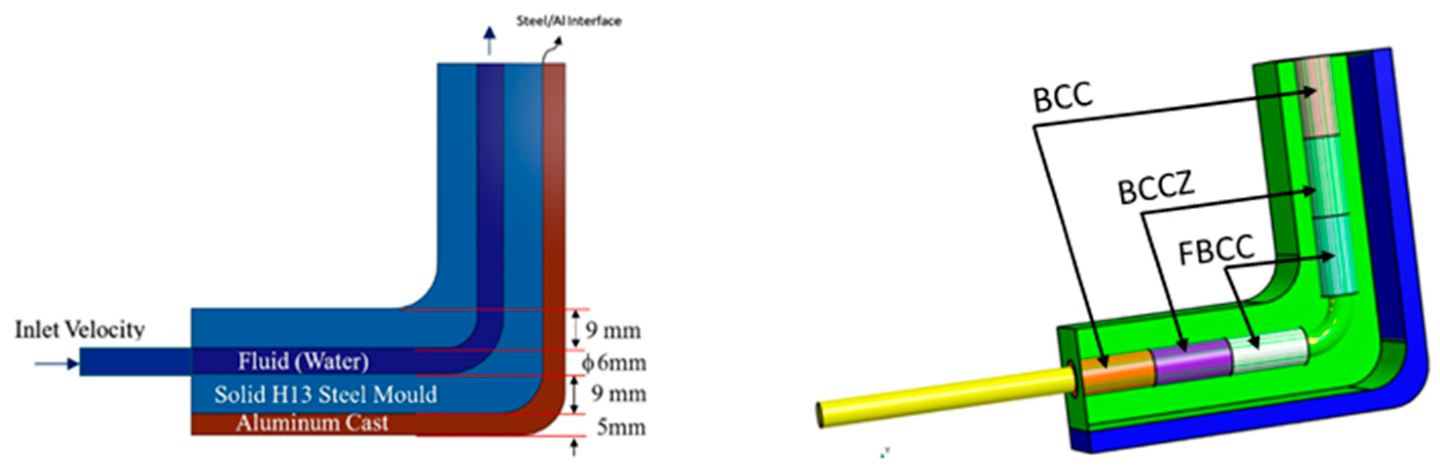
The steady-state model was developed to analyse the heat transfer rate and to identify the temperature distribution while internally cooling an aluminium alloy profile with 90-degree-angled corners with and without lattice structures. The computational domain is divided into three distinct regions: the fluid region (water pipe), the aluminium cast region (treated as a continuous heat generation source), and the mould, which uses the properties of H13 steel.
Three different lattice structure sleeves surrounding the cooling pipe were generated and modelled as solid regions with the equivalent physical and thermal properties of three lattice structures: Body-Centred Cubic Cell (BCC), Face-and-Body-Centred Cubic Cell with Z-axis struts (BCCZ), and Face-Centred Cubic Cell with Z-axis struts (FBCC) [
15].
Figure 1 illustrates the general layout and schematic of the corner cooling channel, where the cast is positioned at the external side of the mould corner with a single cooling channel passing through the mould cavity. The mould block dimension is 80 × 80 mm with a depth of 18 mm. The cooling channel diameter is 6 mm, and the pitch distance between the bottom surface of the pipe and the mould/cast interface is maintained at 9 mm.
Table 1 presents the properties of these three regions and lattice structures. These properties have been identified experimentally using those lattice structures in stagnant air.
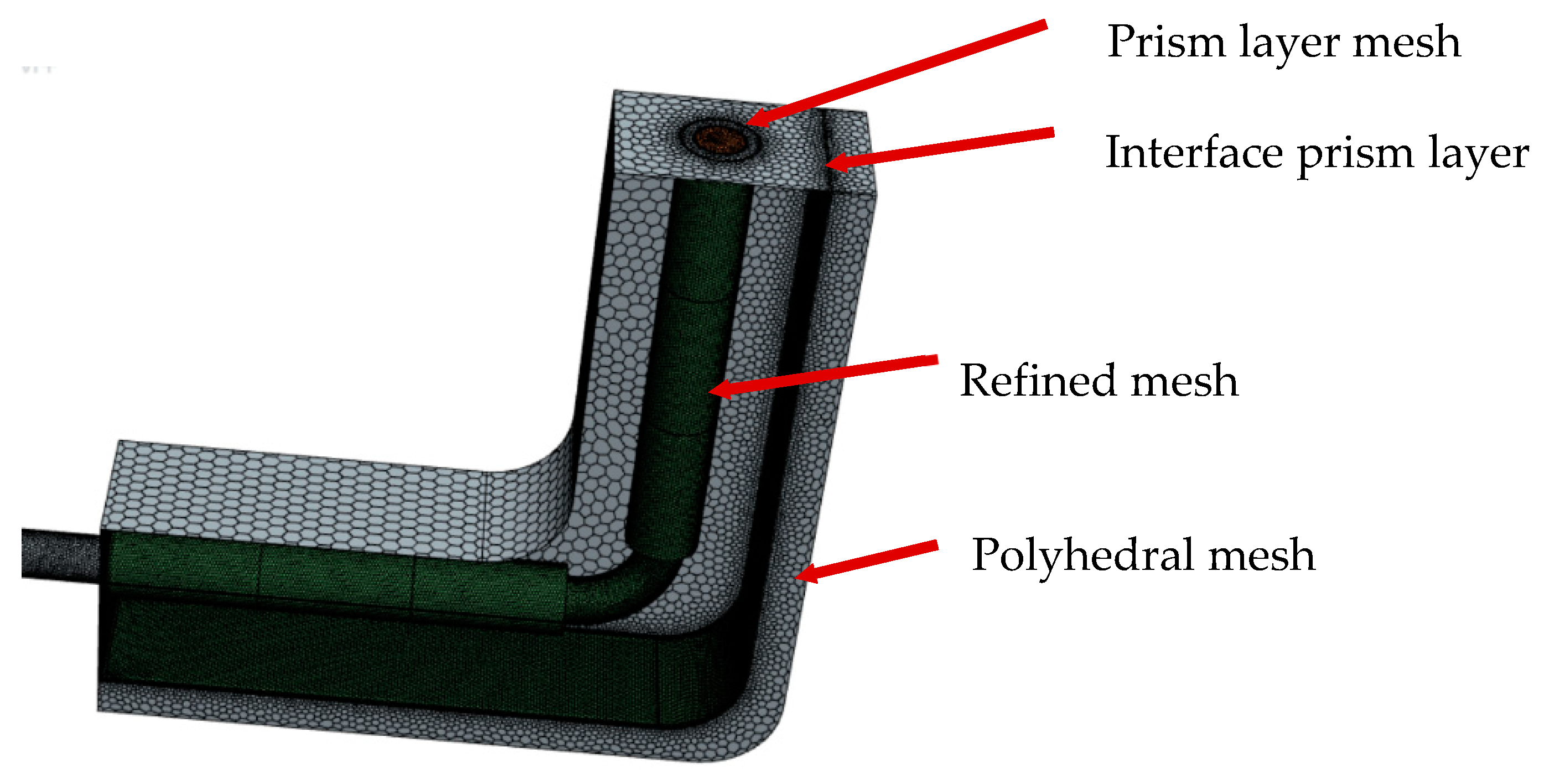
A polyhedral mesh with near-wall prism layers was employed to accurately capture the boundary layer near the walls for accurate evaluation of heat flux at the interface and cooling pipe surface. Various mesh sizes were used within the domain, with finer mesh regions applied to the fluid flow area and near the interface walls, as shown in
Figure 2. The control volume method implemented in the STAR-CCM+ CFD package was used to discretise the governing equations. A mesh convergence study was performed to ensure that the results were independent of mesh resolution. The simulation employed a total cell count of approximately 450,000, with an overall mesh quality of 98.71%, based on evaluations of mesh validity and skewness angle. To address the near-wall viscous transitional sublayer, the all Y+ wall treatment model was used, accommodating different boundary layer mesh densities.
3. CFD and Thermal Model
The steady-state flow model was developed to simulate the coolant flow within the pipe for the aluminium die-casting process in this study. The cast part was modelled as a heat source, with volumetric heat generation evaluated based on the solidification energy throughout the entire casting cycle. The Reynolds-averaged Navier–Stokes (RANS) was employed to solve for the coolant fluid dynamics in the channels. The governing equations for fluid flow—mass, momentum, and energy—are expressed as follows:
In these equations,
ρ represents the fluid density,
denotes the mean velocity,
is the pressure,
signifies the total energy per unit mass, and
represents the heat flux.
I is the identity tensor. A shear-stress transport (SST) k−
ω turbulence model [
21] was employed to model the additional turbulent shear stress. This model offers improved predictions for flow separation and positive pressure gradients and mitigates sensitivity to free-stream and inlet conditions [
21]. The initial temperature of the cast was set to 750 °C. The coolant water was admitted at a constant volume flow rate of 5 L/min and a temperature of 70 °C, with a boundary pressure outlet at the pipe exit. The interface between the cast part and the mould was assumed as a thermal resistance corresponding to an interface heat transfer coefficient of 500 W/m²·K. These conditions were selected to align with previously reported experimental results [
18].
The front and back surfaces of the mould and cast are defined as periodic boundaries, while the remaining boundary surfaces are defined as adiabatic. The cooling process involves extracting heat from the cast until the aluminium alloy material transfers from liquid to solid. This phase change alters the material properties, complicating the analysis. To simplify, the aluminium alloy cast is modelled as a solid with a constant density ρ with a constant volumetric heat generation equivalent to the heat required to cool the aluminium from the injection temperature Tmelt to the assumed demoulding or ejection temperature.
Tdemould is within the moulding time
t. Therefore, the volumetric heat generated by the cast can be evaluated by the following equation:
The temperatures
TS and
TL represent the solidus and liquidus temperatures of the aluminium alloy, respectively.
CpAl,s and
CpAl,l denote the heat capacities of the solid and liquid phases of the aluminium alloy, respectively.
Table 2 provides the values used in the model. The assumption of steady-state heat transfer does not affect the validity of the results or objectives of this study, as it effectively represents a single time step, with all subsequent time steps exhibiting similar behaviour but with different magnitudes. Additionally, the focus of this study is on comparative analysis.
Fourier’s equation for three-dimensional steady-state conductive heat transfer in the solid mould, lattice structure, and cast regions can be expressed as:
The lattice structure is assumed to be a solid part with lower thermal conductivity (k) than H13 solid mould, with the values listed in
Table 1.
All simulations were run until all residuals were below 10−4 and the temperature variation between iterations was less than 0.1% to ensure steady-state conditions were achieved.
5. Results and Discussions
In the following sections, we will present and discuss the temperature distribution for the baseline case, where no lattice structure is applied. The results will emphasize the challenges associated with corner cooling. The subsequent section will introduce the temperature distributions for three proposed lattice structure configurations. We will discuss how these lattice structures influence the corner temperature distribution and address their impact on the cooling performance.
5.1. Baseline Analysis and Understanding the Problem
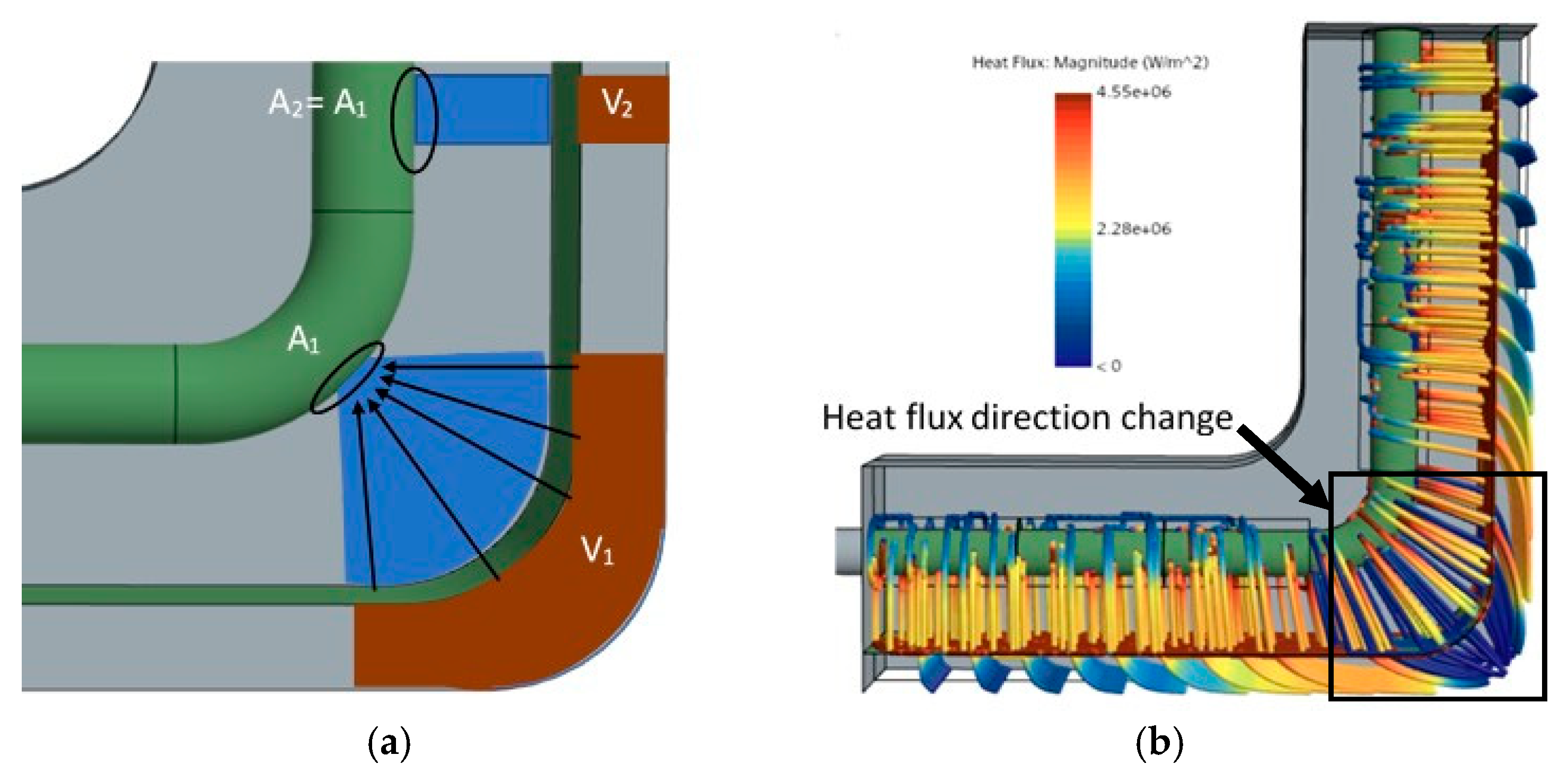
To understand the heat transfer process from the cast part (assumed to be the heat generation source) to the cooling pipes, a schematic diagram and heat flux streamlines are presented in
Figure 3.
Figure 4a illustrates that the volume of the cast at the corner,
V1, is in contact with a limited area on the pipe,
A1, when heat is transferred perpendicularly to the interface. On the corner’s sides, the same area,
A2 =
A1, is available to transfer only a fraction of the heat generated by
V2. This constrained area for heat transfer to the pipe results in high thermal resistance along the perpendicular path.
Because of the high resistance normal for the cast/mould interface, the heat transfer from the corner thus involves two components: one perpendicular to the interface and one parallel. The parallel heat transfer component alters the direction of the heat flux along the sides of the corner, as shown in
Figure 3b. The figure also indicates that the heat path along the sides is longer, with the heat flux decreasing as the distance from the corner increases, eventually becoming perpendicular to the interface further away from the corner. While the interface thermal resistance impedes heat transfer, it assists in adjusting the direction of the heat flux and leads to the temperature gradient along the sides within the mould.
To analyse the temperature variation near the corners of the mould and the molten cast and to evaluate the impact of lattice structures on temperature distribution, temperatures at 19 points along the cast interface were measured and plotted in
Figure 3. This figure represents the baseline case without any lattice structure. It shows how the temperature increases as the located points approach the corner, where the temperature reaches its maximum. It also shows that the rate of temperature increase becomes more pronounced as the points get closer to the corner. This temperature variation along the two sides of the corner is attributed to the parallel heat flux generated at the corner and the low cast volume to cooling surface area compared to that at the corner.
The standard deviation of the temperature measured at the interface was found to be 29 °C, while the difference between the maximum and minimum temperatures at the interface reached approximately 90 °C, which is 32% of the mean temperature value of 282 °C. By examining the temperature distribution along the sides, the data can be segmented into three distinct regions. The first region, starting 10 mm from the corner, exhibits a temperature gradient of 40 °C/cm. The second region shows a gradient of 17 °C/cm, and the third region, 20 mm from the corner, has a gradient of only 5 °C/cm. The location where cracking is observed is usually at the highest temperature gradient region, after the end of the corner curvature. This cracking can be attributed to thermal stress resulting from solidification and contraction of the material on both sides before the corner has fully solidified.
Based on the analysis above, achieving uniform cooling can be accomplished by adjusting the thermal conductivity along the sides of the corner to increase thermal resistance with distance from the corner. However, modifying the thermal conductivity near the cast may impact tool rigidity and cause significant changes in the overall temperature distribution within the tool. The region closer to the cooling channel, which has lower temperatures, can be effectively utilised by surrounding the cooling channel with lattice structures.
By implementing three different thermal resistances along the sides of the corner, temperature variation can be increased. The approach applied here involves using three distinct lattice structures, as described in
Table 1, while maintaining a constant sleeve thickness for all the sleeves.
5.2. Lattice Structure Sleeves’ Effect on Cooling
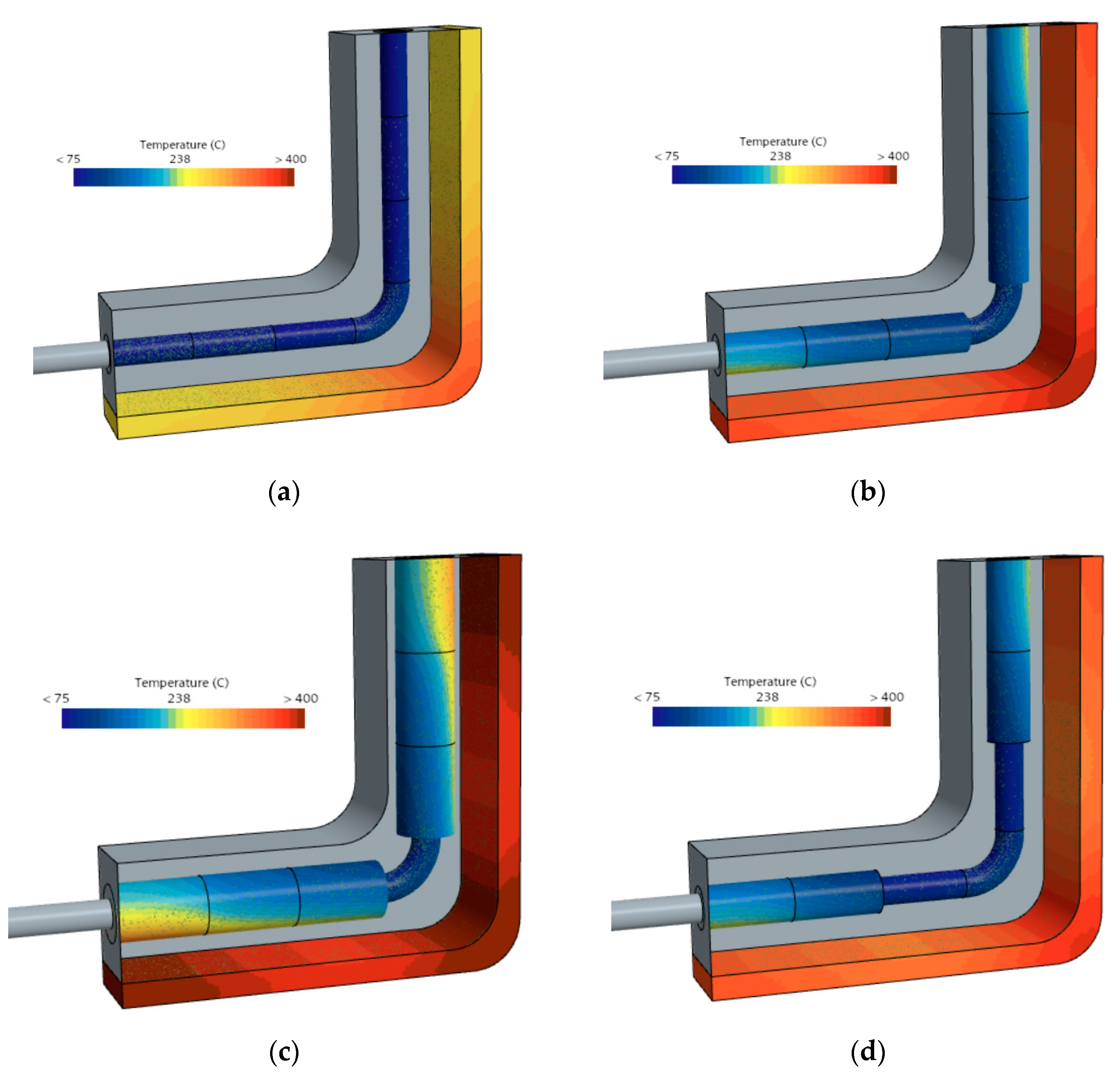
In this section, the cast/mould interface temperature was monitored when applying the three lattice structure sleeves and compared to the baseline design. The temperature distributions at the cast/mould interface, cast surface, and on the surfaces of the lattice structures and cooling pipe are shown in
Figure 5. The figure demonstrates that the previously low temperatures on the two sides of the corner, initially around 240 °C for the baseline, as shown in
Figure 5a, significantly increased and became closer to the corner temperature.
Maintaining the mould interface temperature at 240 °C during moulding can expose the mould to suboptimal temperatures below the threshold for the subsequent cycle after demoulding and lubricant application. Previous studies [
23] have indicated that increasing the die operating temperature from 205 °C to 315 °C can potentially double die production. This improvement in die service life is attributed to reduced dynamic thermal stress due to the smaller temperature differential between the injected hot aluminium and the mould in each cycle.
Figure 5c shows that the temperature at the ends of the corner sides increases to values closer to the corner temperature when a 3 mm thick FCC lattice sleeve is applied, compared to the 1.5 mm sleeve thickness shown in
Figure 5b. In all three cases, the temperature distribution in the cast part is improved relative to the baseline case. However, it is notable that the corner temperature also increases, suggesting that the imposed restrictions on heat transfer have an impact on cooling efficiency at the corner.
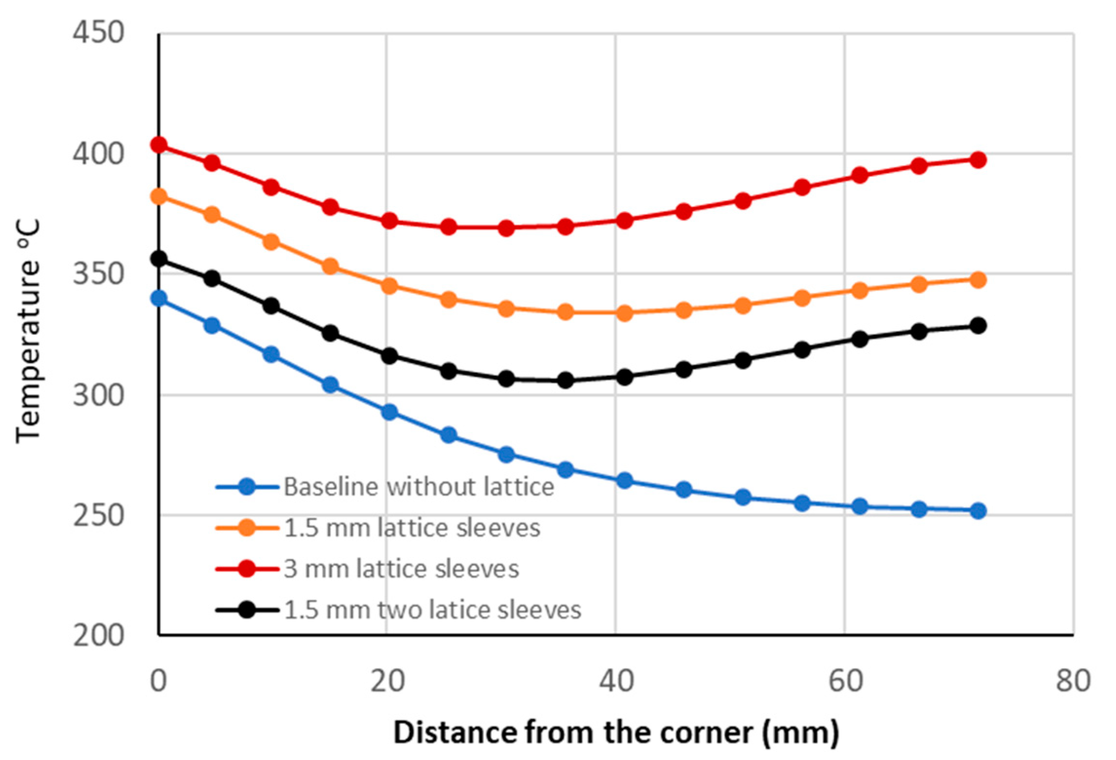
To further assess the impact of lattice structure sleeves on corner temperature, the temperature variation along the side of the corner was evaluated using the probe points shown earlier in
Figure 4. As illustrated in
Figure 6, all three cases exhibit reduced temperature variation; however, the corner temperature increases as the thermal resistance imposed by the lattice structure increases. Specifically, the corner temperature rises from 340 °C to 370 °C and 400 °C for the 1.5 mm and 3 mm sleeves, respectively. By removing the closest lattice structure to the corner while retaining the others and using 1.5 mm sleeves, the corner temperature increases to 356 °C, which is still slightly higher than the corner temperature without the sleeves (16 °C difference). Nevertheless, this configuration results in more uniform cooling distribution across the cast part, with a small rise in corner temperature. The difference between the maximum and minimum temperatures decreases from 88 °C in the baseline case to 50 °C along the selected probe points, representing approximately a 42% improvement in temperature uniformity.
The rate of heat transfer is directly proportional with the temperature difference and inversely proportional with thermal resistance. By adding additional thermal resistance using lattice structures on the two corner sides, the average mould/cast interface surface temperature increases, with a greater temperature rise on the sides compared to the corner, thereby improving temperature uniformity. The increase in corner temperature may lead to longer moulding times (cycle time) if the corner is the hottest location in the entire industrial mould. However, as long as the corner temperature remains lower than the hottest location, the method enhances uniformity without sacrificing cycle time. To reduce the corner temperature, additional techniques targeting hot spots, such as the use of bubblers or positioning cooling channels closer to the corners, can be combined with the lattice structure method. Therefore, this approach can complement existing methods to achieve better temperature uniformity.
Table 3 presents the mean and standard deviation of temperatures calculated at the cast interface surface, along with the difference between the maximum and minimum temperatures on this surface. The results indicate that increasing insulation with 3 mm lattice sleeves raises the average interface temperature, and it leads to more uniform temperature distribution. However, as previously discussed, this uniformity is achieved at the expense of an elevated corner temperature. The results for 1.5 mm thick sleeves across all three lattice structures are comparable to those obtained with a two-sleeve configuration. Nevertheless, the two-sleeve arrangement results in a less pronounced increase in corner temperature and a lower average temperature.
As demonstrated in a previous study [
1], conformal cooling can significantly enhance cooling efficiency and reduce cycle time by up to 70%, thereby increasing production rates. Additionally, it can extend the service life of 3D-printed tools by up to three times [
18]. However, conformal cooling alone is not sufficient in complex geometries with small features that can be exposed to overcooling or overheating. The results of this study demonstrate that the lattice structure can limit the local heat transfer by increasing the thermal resistance in such regions. While this method has been applied to mould corners, it can be utilized in any local region within the mould. This study has introduced a new approach to controlling the cooling rate in specific regions by utilising lattice structures with thermal conductivity lower than that of solid tool steel. Future work will focus on validating the model after implementing the lattice structure and implementing lattice structures in multiple locations inside the mould to control heat transfer pathways.
6. Conclusions
This study is focused on achieving temperature uniformity on the mould/cast interface near corners by implementing three types of lattice structure with known geometry and thermal conductivity, as previously measured and published in a prior study [
3]. The investigation was further constrained to a specific configuration involving corner cooling, utilising a cylindrical cooling channel surrounded by lattice structure sleeves of two thicknesses: 1.5 mm and 3 mm. A three-dimensional steady CFD model is developed to assess the uniformity of the local average temperature over the cast/mould surface. The findings from the thermal model can be summarised as follows:
Incorporating lattice structures can enhance temperature uniformity within the cast, leading to a more consistent cast/mould interface temperature.
Applying lattice structures on both sides of a corner improves cooling uniformity, but it also results in an increase in the maximum corner temperature.
The use of lattice structures as a means to improve cooling uniformity must be carefully optimised to avoid extending the moulding time for the entire casting process.
Lattice structures should be strategically implemented in regions where overcooling occurs and positioned at an appropriate distance from overheated areas to prevent further temperature increases in these hot spots.
Lattice structures in 3D-printed tools are integrated into the mould without additional cost, as they use the same material. However, the location and size of the lattice must be optimised. While the method is applied to mould corners, it can also be used in other regions of the 3D-printed mould or insert where overcooling occurs.


