1. Introduction
With the rapid unplanned growth of cities and increasing constraints on surface transportation, the construction of underground infrastructure has attracted increasing attention. Tunnel boring machines (TBMs) are essential for tunnel excavation and are widely used in highway, railway, and water diversion projects [
1,
2,
3]. TBMs break rock through the interaction between the disc cutter and rock, and their rock-breaking efficiency directly affects the overall construction progress. However, complex geological conditions during excavation result in highly variable and intricate forces acting on the disc cutters [
4]. For instance, TBMs operating in fault zones encounter significant challenges due to fault fracture zones, which cause an increased deformation of the surrounding rock and the development of plastic zones along the fault belt. Additionally, the convergence deformation of the surrounding rock and plastic zone expansion at the arch bottom within the fault zone often increase, leading to potential cutter head sinking and “bottom bulging” of the surrounding rock. These conditions create complex force dynamics for TBM operations in fault zones. The improper selection of disc-cutter types or designs under such conditions can reduce rock-breaking efficiency, delay construction schedules, and even pose safety risks.
To minimize unnecessary cutter wear and improve efficiency, researchers have explored various optimization strategies for cutter layouts, rock-breaking mechanisms, and tunneling parameters. Xia et al. [
5] and Yang et al. [
6] developed calculation models for key parameters, such as cutter layout and design, based on geological conditions and structural parameters, introducing a geological adaptive design method for TBM disc cutters. Liu et al. [
7] investigated the crack initiation life of TBM disc cutters under different geological conditions and developed a geological matching calculation model based on crack initiation. Lou et al. [
8] analyzed the compound rock-breaking characteristics of impact disc cutters, derived cutting load equations, and established models for rock fragmentation volumes. Jiang et al. [
9] investigated the wedge-induced rock-breaking performance of disc cutters on prefabricated fractured rocks, identifying three stages in the rock-breaking process: the compressive stage, the stress accumulation stage, and the fragmentation stage, based on cutter load fluctuations and acoustic emission characteristics. Zhang et al. [
10] conducted experiments and simulations to compare the rock-breaking mechanisms of TBM disc cutters under traditional and free-face conditions, concluding that free-face conditions reduce rock-breaking force and improve efficiency.
Theoretical analysis has limited applicability, and laboratory experiments are often time-consuming, costly, and inadequate for investigating crack development patterns. In contrast, numerical simulation techniques offer a cost-effective alternative for simulating the rock-breaking process, yielding promising results. Hu et al. [
11] developed a finite element model for disc-cutter rock breaking using LS-DYNA, analyzing rolling processes and rock fracture patterns, and identified three fracture modes: forward slip, no slip, and backward slip. Yang et al. [
12], using PFC 6.0 simulation software to explore rock-breaking patterns for various cutter configurations (single edge, double edge, and triple edge), discovering that increasing the number of cutters reduced the vertical force and torque per cutter. Li et al. [
13] examined factors affecting TBM disc-cutter efficiency in deep rock excavations, including confining pressure, penetration, cutter spacing, and revolution speed. Their results showed that cutter spacing had the most significant impact on rock-breaking specific energy. Yu et al. [
14] used Matrix Discrete Element Method (MatDEM 2.0) software to investigate the rock-breaking mechanism of disk cutters at soil–rock interfaces. Comparative analysis has demonstrated that a numerical simulation can have significant advantages in exploring disc-cutter rock breaking, leading to its growing use by researchers in related studies [
15,
16,
17].
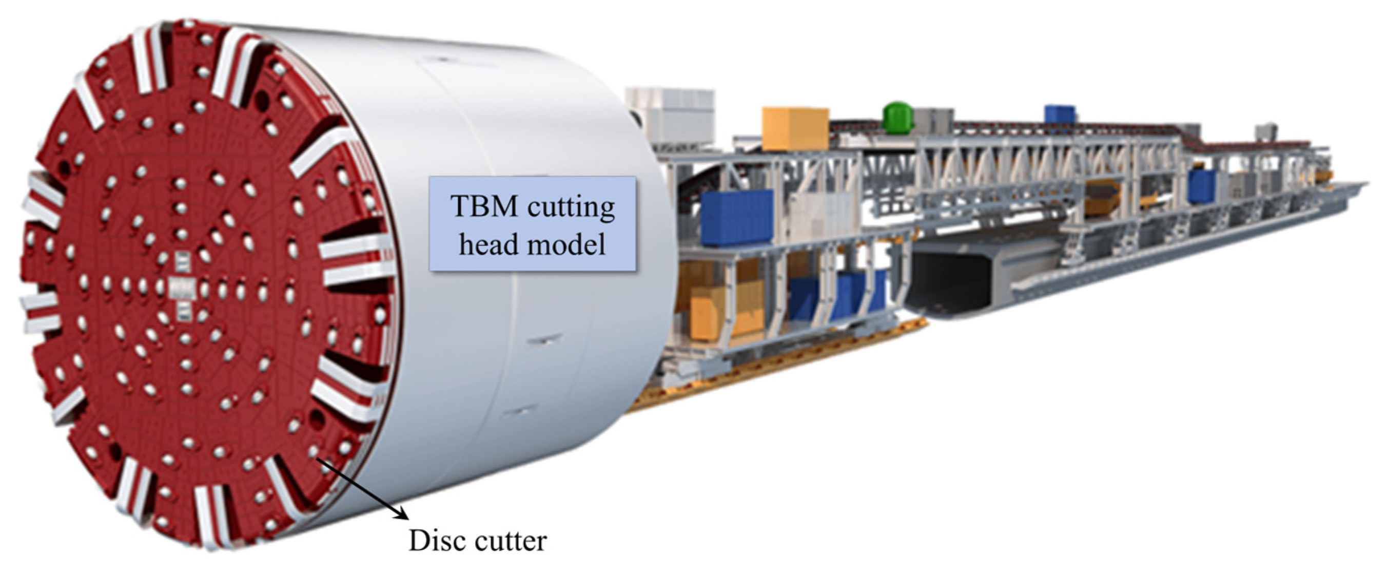
Figure 1 illustrates a TBM cutting head, which features numerous disc cutters. The efficiency of TBM tunneling depends on factors such as disc-cutter size, spacing, and penetration, all of which affect the rock-breaking performance. Zhu [
18] used ABAQUS to establish a finite element model of disc-cutter rock breaking, examined the effects of cutter diameter on rock-breaking forces, and generated comprehensive relationship curves. Xue et al. [
19] employed MatDEM software to create a large-scale 3D model for disc-cutter rock breaking, analyzing the changes in cutting forces and specific energy under varying cutter spacings and penetrations. They identified an optimal cutter spacing-to-penetration ratio that minimized specific energy for rock breaking in uniform rock materials. Through experiments and finite element simulations, He [
20] explored the effects of cutter spacing and penetration on rock-breaking performance and established a mechanical model for optimal cutter spacing during cooperative rock breaking.
The study of TBM disc-cutter rock-breaking mechanisms, particularly through discrete element modeling, offers valuable insights for cutter design and tunnel parameter optimization, ultimately improving efficiency and safety. Discrete element techniques are particularly effective for analyzing rock–cutter interactions. These simulations help to understand the dynamic processes of rock breaking, including fracture modes and cutter wear mechanisms, and are essential for cutter design and parameter selection. Optimized cutter designs and tunneling parameters can reduce construction durations, lower costs, and decrease cutter replacement frequencies, thereby enhancing the economic and social benefits of large-scale infrastructure projects.
Despite significant progress, the existing studies lack systematic investigations into the factors influencing disc-cutter rock-breaking performance. Using validated numerical models can provide more objective and reliable insights. In this study, we developed a 3D discrete element model for rock breaking using disc cutters and validated it by comparing the simulation results with the experimental and finite element data from the literature. The effects of disc-cutter diameter, cutter spacing, and penetration on rock-breaking performance were systematically analyzed.
2. Establishment of a 3D Rock-Breaking Model for Disc Cutters
2.1. Structure of Disc Cutters
Disc cutters are a critical component of TBMs used for rock breaking. Their structure typically comprises four main parts: the cutter ring, cutter hub, cutter shaft, and disc-cutter seal. This modular design facilitates the easy disassembly and replacement of individual components. The cutter ring, an annular body with cutting edges, serves as the primary cutting element and is responsible for rock fragmentation, as shown in
Figure 2. It is securely attached to the cutter body, which constitutes the hub section of the disc cutter.
Based on the number of cutter rings on the cutter hub, disc cutters can be classified into single-disc, double-disc, and multi-disc cutters. Among these, single-disc cutters are the most commonly employed configuration in full-section TBMs. The primary distinction between single- and double-disc cutters lies in the number and arrangement of blades on the cutter ring, which significantly influence their rock-breaking mechanisms and application scenarios. Single-disc cutters produce larger rock fragments and more extensive rock fissures, whereas double-disc cutters apply higher extrusion pressure to the rock mass, resulting in finer gravel and rock debris. Single-disc cutters fracture rock through repeated compressive forces that generate tensile cracks, while double-disc cutters rely on synergistic interactions between the hobs for effective rock fragmentation. Each type has distinct advantages, and the choice between single- and double-disc cutters should be determined based on specific geological conditions and engineering requirements.
A TBM cutter head can accommodate dozens to hundreds of disc cutters. Ensuring optimal rock-breaking efficiency requires determining the ideal cutter spacing. If the spacing, S, is too large, the cracks generated by adjacent disc cutters may not intersect, leaving unbroken rock between them. Conversely, excessively small cutter spacing leads to the over-penetration of cracks, resulting in unnecessary energy loss. Optimal cutter spacing is achieved when the cracks generated by adjacent disc cutters fully penetrate the rock. This optimal spacing enhances the rock-breaking efficiency, minimizes cutter wear, accelerates the driving speed, improves the construction schedule, and reduces the risk of abnormal TBM failures.
2.2. Discrete Element Method
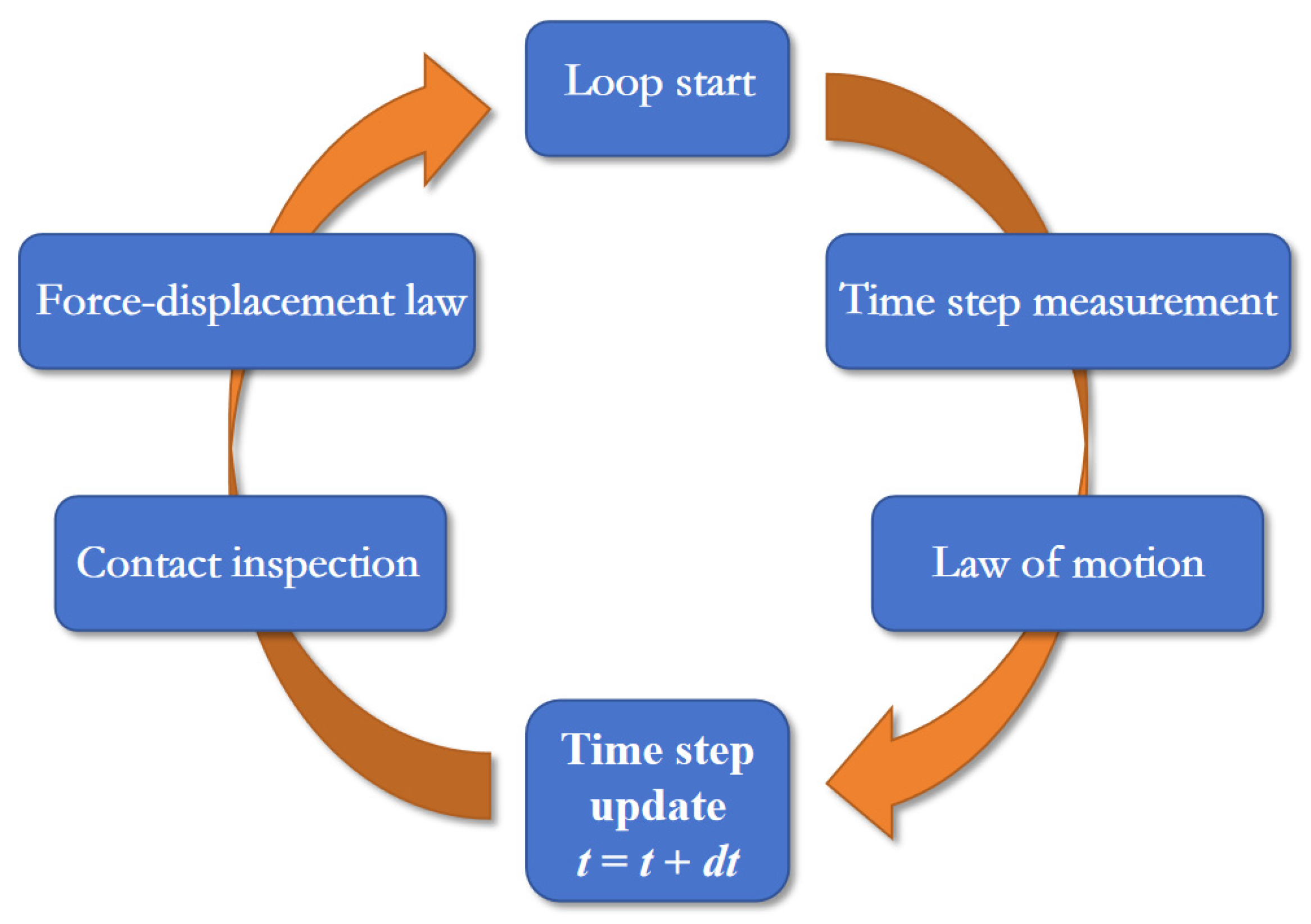
The discrete element method (DEM) models rock as an assembly of particles, each considered a separate body subject to forces and moments exerted by neighboring particles. DEM simulations solve the equations of motion for the entire system based on Newton’s second law and constitutive models. Explicit iterative calculations are performed, as illustrated in
Figure 3, where Newton’s second law and force–displacement relationships are repeatedly applied.
DEM employs several assumptions for numerical calculations:
- (1)
Each particle is treated as a rigid body.
- (2)
Contact occurs over a small area: as a line segment in 2D and a disk in 3D.
- (3)
Contact is flexible, allowing small overlaps at contact points.
- (4)
Bond strength exists at the contact interface.
Particles in the DEM can move in two ways: translational motion and rotational motion about their center. The translational motion is governed by the following vector equation:
where
Fi is the vector sum of the external forces acting on a particle;
m is the particle mass; and
g is the acceleration of gravity.
Rotational motion is described by the following equation:
where
Mi is the sum of all external torques, and
Hi represents the angular momentum.
The following Euler equations of motion can be obtained from Equation (2):
where
ω1,
ω2, and
ω3 represent the angular accelerations of the spherical particles along three different directions;
M1,
M2, and
M3 are the components of the resultant torque acting on the spherical particles along each coordinate axis.
I1,
I2, and
I3 are the components of the moment of inertia of the particles along the spatial coordinate axes, and their values are identical for spherical particles.
Cracks are generated when contact forces exceed the bond strength. Tension cracks occur when the normal force exceeds the tensile strength or becomes negative, while shear cracks form when the tangential force exceeds the shear strength.
2.3. Three-Dimensional Rock-Breaking Model for Disc Cutters
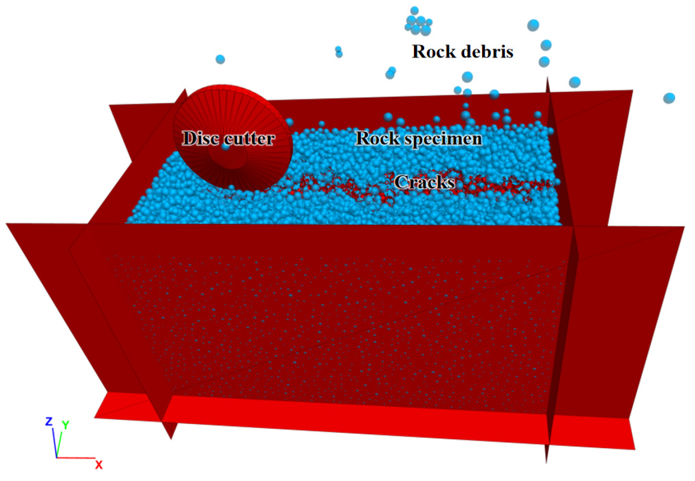
A 3D rock-breaking model was developed to simulate the interaction between disc cutters and rock, as shown in
Figure 4. The model dimensions are 200 mm in length, 100 mm in width, and 100 mm in height, containing 46,271 particles. A 17-inch disc cutter with a diameter of 43.2 cm and a blade width of approximately 8 mm was used. The mechanical behavior of rocks was modeled using the parallel bond model (PBM) developed by Potyondy and Cundall [
21]. In the PBM, particle contacts are connected via parallel bonds, which act as springs with stiffness properties. These bonds transmit both forces and moments and possess tensile and shear strengths.
Microscopic PBM parameters include contact modulus, a normal-to-shear stiffness ratio, bond strengths (normal and shear), and bond friction angle. The macroscopic mechanical parameters derived from these include cohesion, internal friction angle, and Poisson’s ratio. The parameters for granite in this study were calibrated using a trial-and-error method: (1) Initial adjustments of shear and normal bond strengths to align simulated shear strength values with experimental data; (2) Fine-tuning of the contact modulus, stiffness ratio, and bond friction angle to ensure the simulated results matched the shape of laboratory test results; and (3) Final adjustments to optimize calibration.
The microscopic parameters of the granite rock sample are listed in
Table 1. The physical and mechanical properties of granite, along with the calibration results, are provided in
Table 2.
3. Simulation Verification of the Rock-Breaking Process by Disc Cutters
To validate the accuracy of the calibrated discrete element numerical model in simulating the rock-breaking process by disc cutters, a simulation (
Figure 5) was conducted and compared against finite element simulations and the experimental data from the literature. In the model, the disc cutter’s rotational speed was set to 2 r/min, corresponding to an angular velocity of 3.7 rad/s. Penetration depths, defined as the cutting depth of the disc cutter, were set at 2, 2.5, 3, 3.5, and 4 mm. As the disc cutter rolled from the right to the left of the model, it fragmented the underlying rock, and the rolling force and rock-breaking specific energy were monitored throughout the process.
To objectively evaluate the rock-breaking efficiency of the disc cutter, two indicators were used: the cutter rolling force and rock-breaking specific energy. During the rock-breaking process, the three-dimensional forces acting on the disc cutter contribute to rock fragmentation. However, the cutter primarily relies on the rolling force to overcome rock resistance, as illustrated in
Figure 6. The lateral force is relatively small compared to the rolling force, while the normal force has been extensively studied by other researchers [
22,
23]. Therefore, this study focused on the variation in rolling force under different tunneling parameters.
While the rolling force is critical, it alone is insufficient to fully evaluate the efficiency and energy consumption of the rock-breaking process. To address this, a new indicator, rock-breaking specific energy (denoted as
A), was introduced. This combines the rolling force and the rock fragmentation volume and is defined as:
where
W is the work performed by the rolling force to break the rock, and
V is the volume of the resulting rock fragments.
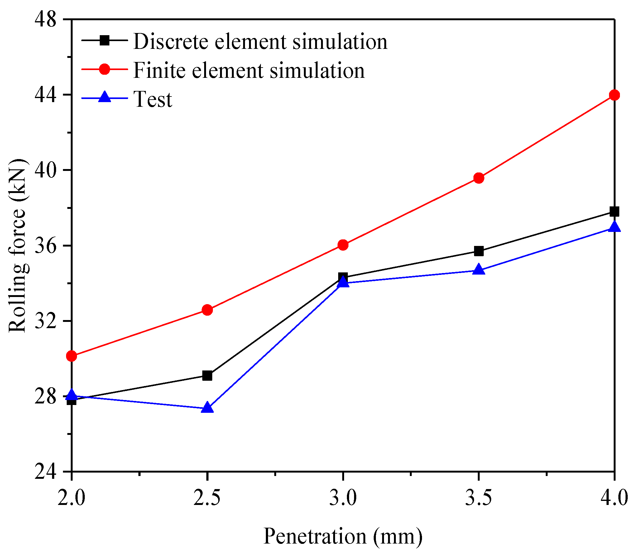
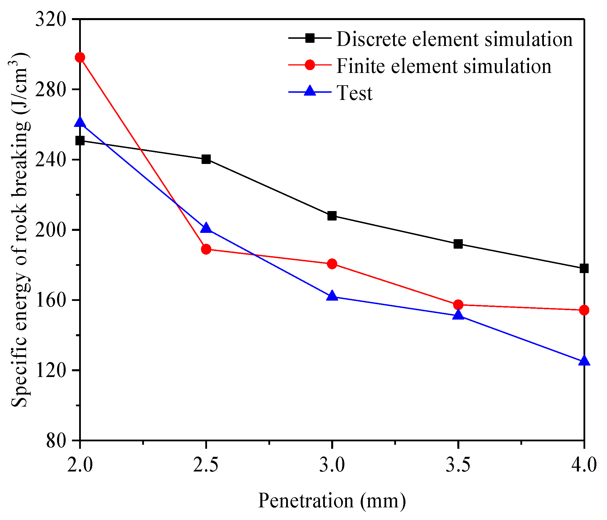
Figure 7 and
Figure 8 compare the simulation results with the experimental data and finite element simulations for rolling force and rock-breaking specific energy, respectively. The experimental and finite element data were sourced from reference [
20], see
Table 3. The rolling force increased as the penetration depth increased, while the specify energy decreased as the penetration depth increased. From the perspective of the rolling force, the experimental results are the smallest, with a minimum value of 27.3, a maximum value of 36.9, and an average value of 32.2. The finite element simulation results are the largest, with a minimum value of 30.1, a maximum value of 43.9, and an average value of 36.4. The discrete element simulation results fall in between, with a minimum value of 27.8, a maximum value of 37.8, and an average value of 32.9. In terms of rock fragmentation energy, the experimental results are the smallest, with a minimum value of 124.8, a maximum value of 260.7, and an average value of 179.8. The discrete element simulation results are the largest, with a minimum value of 178, a maximum value of 250.8, and an average value of 213.8. The finite element simulation results are intermediate, with a minimum value of 154.2, a maximum value of 298.2, and an average value of 195.8.
The rolling force values obtained from the DEM closely align with the experimental results, demonstrating high accuracy. However, the specific energy values derived from the DEM deviate slightly from the experimental results. This discrepancy may arise because, in the DEM simulations, rock fragmentation occurs when the tensile or shear stress on particles exceeds their respective strengths. This mechanism can produce fewer fragments during particle breakage, reducing the fracture area. Conversely, finite element method (FEM) simulations involve more complex stress states and crack propagation paths, resulting in more extensive fragmentation and larger fracture areas.
Despite these differences, the DEM simulation results for rolling force and rock-breaking specific energy fall between the FEM and experimental results, closely aligning with the experimental data. This demonstrates that the calibrated DEM model effectively simulates the rock-breaking process by disc cutters. As such, the model provides a reliable tool for analyzing rock-breaking behavior under various tunneling parameters.
4. Simulation Analysis of Different Tunneling Parameters
4.1. Effect of Disc-Cutter Diameter on Rock Breaking
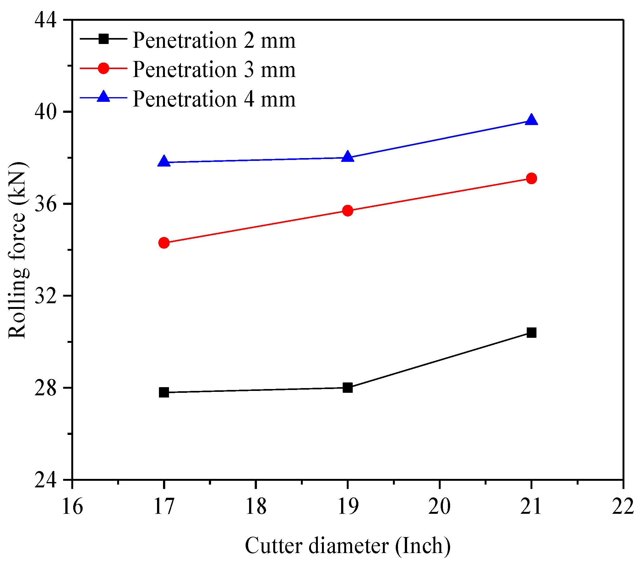
The 17-inch disc cutter is the most commonly used in TBMs. However, in challenging geological conditions, such as fault fracture zones, deep burial, high geostress, water-rich areas, larger disc cutters—19-inch or 21-inch—are sometimes employed to improve rock-breaking efficiency and reduce cutter wear. Larger disc cutters can sustain higher loads, resulting in greater forces during rock breaking. Although larger diameters generate higher forces per rotation, they have fewer rotations to achieve the same amount of rock fragmentation, leading to reduced wear over time.
Figure 9 shows the rolling forces for disc cutters of varying diameters under different penetration levels. The rolling force increased with the cutter diameter, although the increase was not substantial.
Figure 10 illustrates the relationship between cutter diameter and rock-breaking specific energy, showing that specific energy initially decreased and then increased as diameter grew. The 19-inch disc cutter achieved lower specific energy compared to the 17-inch and 21-inch cutters. This is because, while the 19-inch cutter generated higher rolling force than the 17-inch cutter, it also produced a larger rock fragmentation volume, thereby reducing specific energy.
Overall, the 19-inch disc cutter demonstrates a slightly higher rock-breaking efficiency, making it suitable for conventional tunneling operations. In hard rock formations (defined as rocks with a uniaxial compressive strength exceeding 70 MPa), the 21-inch disc cutter may be preferable due to its ability to reduce cutter replacement frequency, minimizing downtime caused by wear.
The studies by Xia et al. [
5] and Yang et al. [
6] focused on geological adaptability development, while Liu et al. [
7], Jiang et al. [
9], and Zhang et al. [
10] concentrated on the rock-breaking mechanisms. In contrast, our study provides more specific guidance for engineering applications by systematically analyzing the impact of varying disc-cutter diameters on rock-breaking efficiency, a topic less explored in previous research. Through experimental and simulation validations, our findings contribute valuable insights for the design optimization of TBM disc cutters and tunneling parameters.
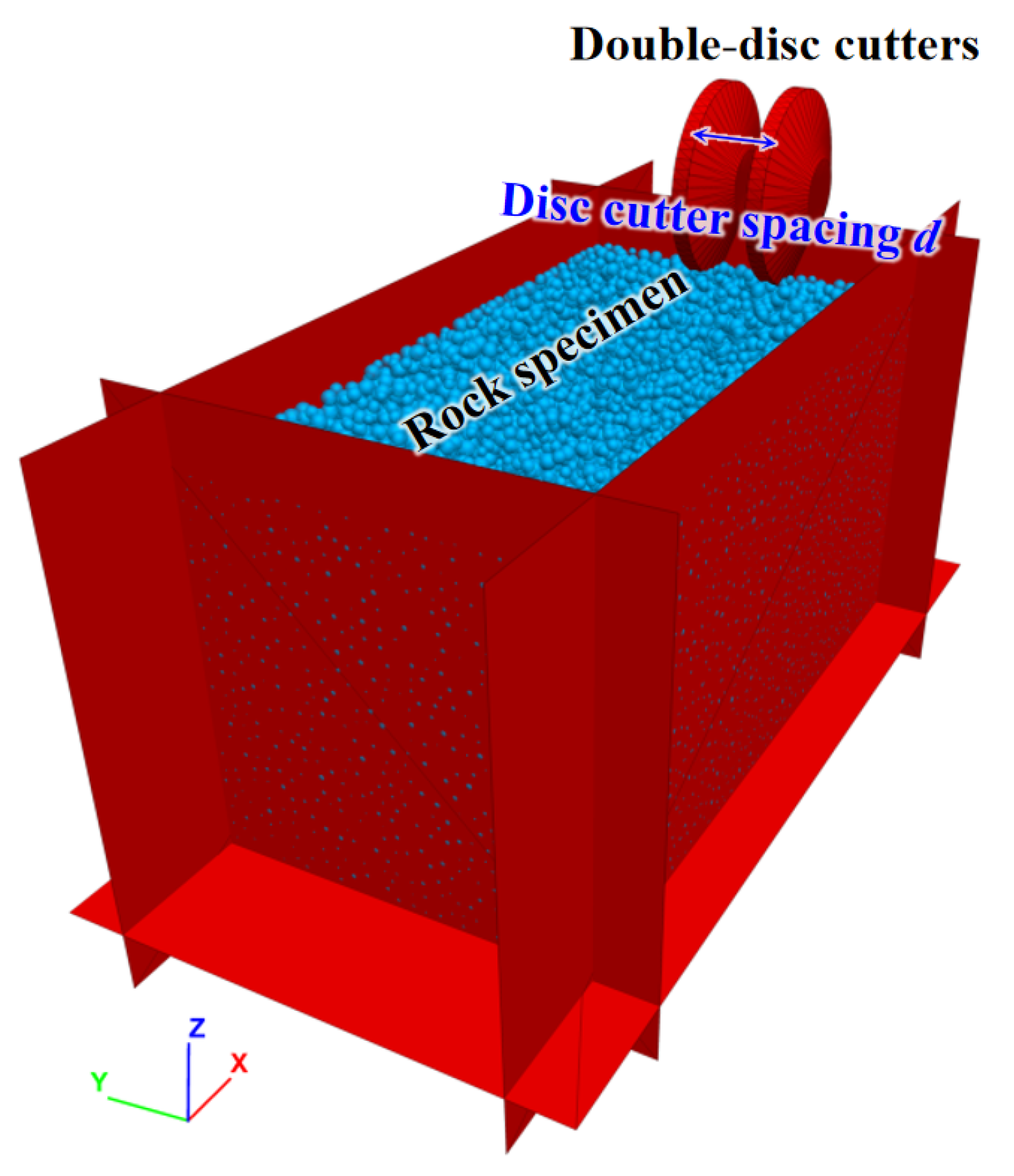
4.2. Effect of Disc-Cutter Spacing on Rock Breaking
To analyze the effect of cutter spacing, the 3D single-disc cutter rock-breaking model (
Figure 4) was modified to incorporate a double-disc cutter configuration (
Figure 11). Cutter spacings were varied at 30, 40, 50, 60, 70, and 80 mm.
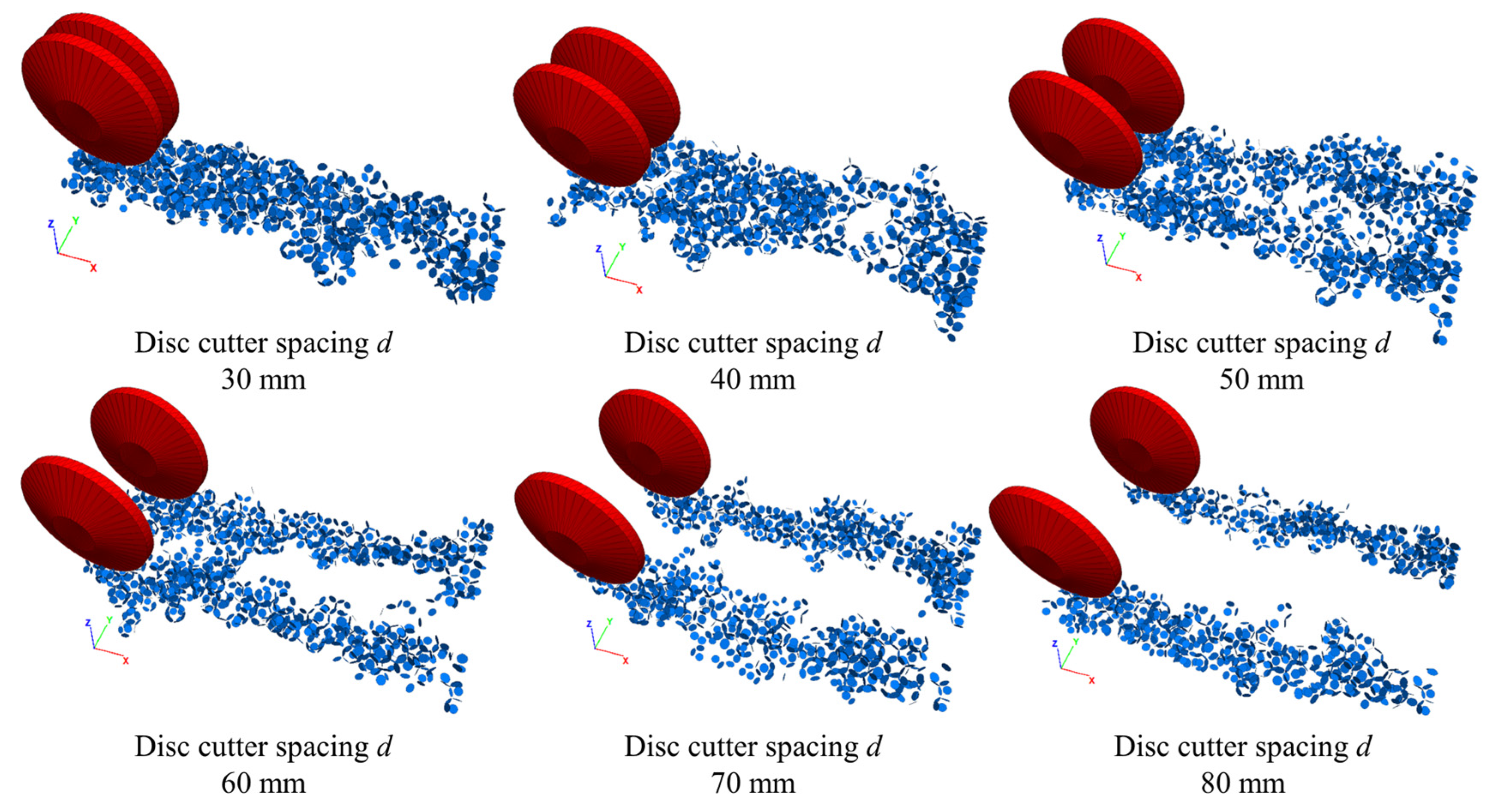
Figure 12 demonstrates how cutter spacing influences crack formation. When the spacing was 30–40 mm, cracks from the two cutters merged, producing a smaller rock fragmentation volume. At 50–60 mm spacing, cracks interconnected between cutters, creating larger fragmentation volumes. When the spacing was increased to 70–80 mm, each cutter acted independently, with cracks failing to connect. This led to ridges forming between cutting paths, reducing fragmentation volume and efficiency.
The cooperative action of adjacent cutters enhances rock fragmentation. However, as cutter spacing increases, the interaction diminishes, resulting in incomplete rock fragmentation and lower efficiency. Conversely, excessively small spacings limit crack propagation, causing overlapping cracks and reducing fragmentation volume.
The appropriate spacing of cutters directly affects the efficiency of tunnel excavation and the associated costs. If the spacing between cutters is too large, it can lead to incomplete rock fragmentation and reduced drilling efficiency. Conversely, if the spacing is too small, it can cause excessive cutter wear and energy waste. Therefore, determining the optimal cutter spacing is essential for fine-tuning excavation parameters, enhancing construction safety and economy. This study provides scientific evidence on the impact of different cutter spacings on rock fragmentation, assisting tunneling teams in making more informed decisions in practice, thereby improving construction efficiency, reducing resource consumption, and lowering project risks.
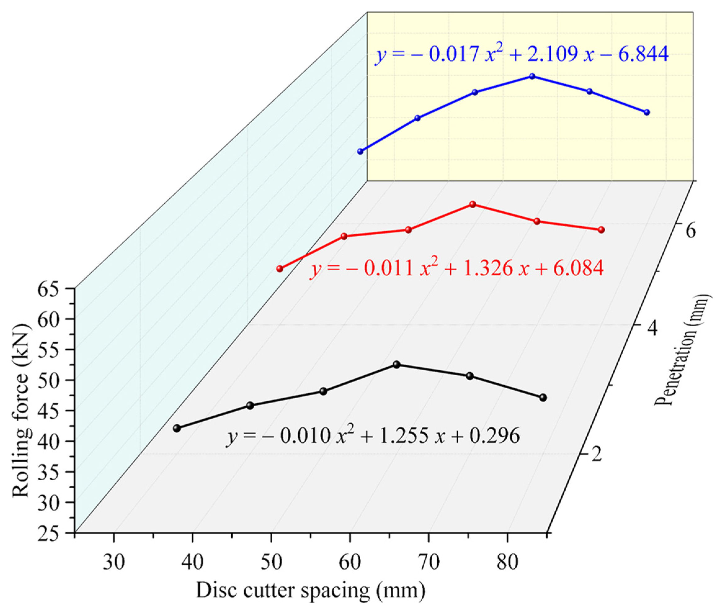
Figure 13 and
Figure 14 depict the effects of cutter spacing on rolling force and specific energy. The rolling force increased with spacing before peaking at 60 mm, then declined. Similarly, specific energy decreased initially, reaching a minimum at 60 mm, and then increased. At 2 mm penetration, the rolling force was smallest, while specific energy was highest. At 4 mm penetration, the rolling force and specific energy were moderate. At 6 mm penetration, the rolling force peaked, while specific energy reached its lowest value due to the higher rock fragmentation volume.
A quadratic function was used for regression fitting, and the fitted formulas are shown in
Figure 13 and
Figure 14. The optimal cutter spacing for maximum rolling force averaged 61.68 mm across penetration depths of 2, 4, and 6 mm. For specific energy, the optimal spacing averaged 61.22 mm. Therefore, a cutter spacing of 60 mm is recommended for tunneling in granite formations to achieve the highest efficiency and lowest energy consumption.
Liu et al. [
13] demonstrated that disc-cutter spacing significantly influences the specific energy consumption of rock breaking, while Xue et al. [
19] identified the optimal disc-cutter spacing-to-penetration ratio that minimizes the specific energy of rock breaking. Our study complements these findings by offering a more detailed analysis of the relationship between disc-cutter spacing and rock-breaking efficiency. He et al. [
20] examined the effects of cutter spacing and penetration on rock-breaking performance through experiments and finite element simulations, developing a mechanical model for optimal spacing in cooperative rock breaking. Utilizing the discrete element method, our study expands on He et al.’s research with a more detailed analysis on the impact of disc-cutter spacing on rock-breaking efficiency. Compared to the results of other researchers, this study provides a more in-depth analysis and more specific engineering application recommendations.
4.3. Effect of Penetration on Rock Breaking
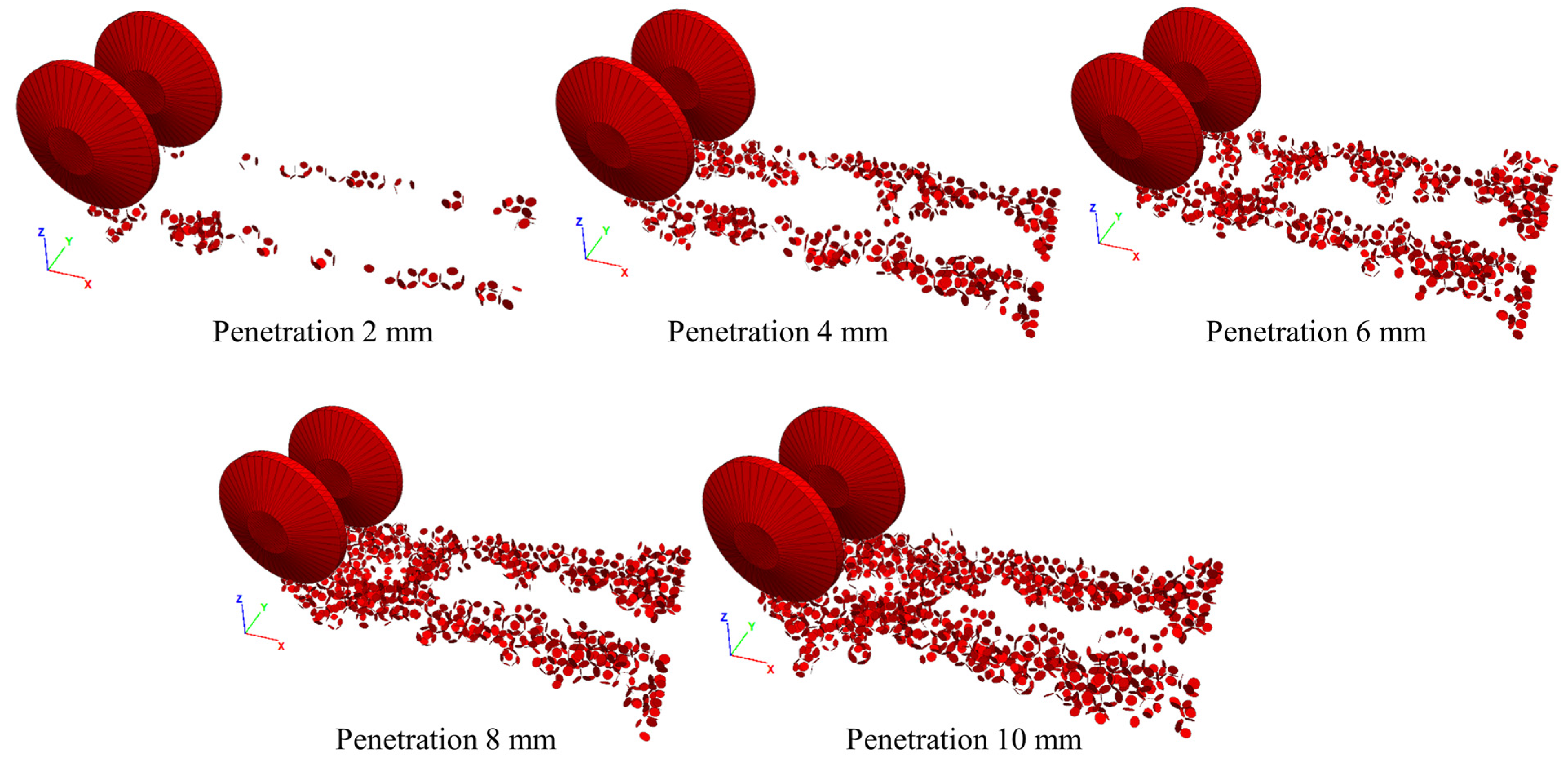
Penetration is a critical parameter that significantly influences rock-breaking efficiency.
Figure 15 illustrates the effect of penetration on crack formation. As penetration increased, the depth of cutter entry into the rock mass grew, generating more cracks and a larger fragmentation volume. Increased penetration also reduced the spacing between ridges in the cutting paths, allowing cracks to interconnect more effectively, further enhancing fragmentation.
The transition from uncoordinated to coordinated rock-breaking occurred as penetration increased. This coordination improved energy usage efficiency, as crack propagation accelerated and the volume of fragmented rock increased. Consequently, specific energy decreased, while rolling force steadily increased due to greater friction and resistance between the cutter and rock.
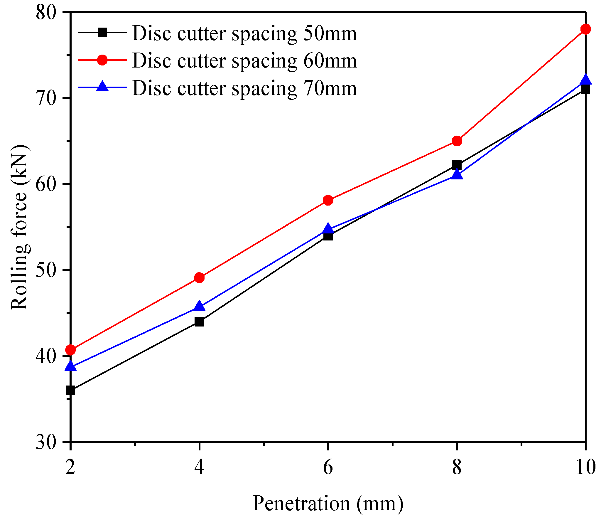
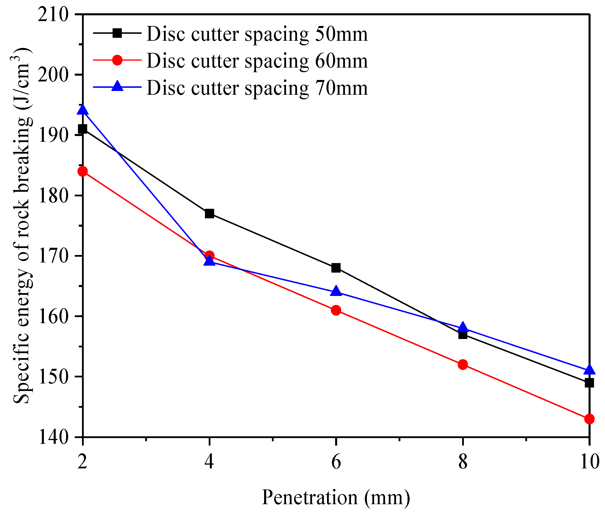
Figure 16 and
Figure 17 show the effects of penetration on rolling force and specific energy, respectively. Rolling force increased with penetration as deeper cuts required greater energy to overcome friction and resistance. Specific energy decreased with penetration because the rate of increase in the rock fragmentation volume exceeded that of rolling force.
When penetration ranged between 2 and 10 mm, the rock-breaking efficiency improved consistently. This was attributed to enhanced crack propagation, increased cutter synergy, and the generation of a greater volume of rock fragments. Thus, appropriately increasing penetration significantly enhances rock-breaking efficiency.
Hu et al. [
11] developed a finite element model using LS-DYNA to study rock breaking by disc cutters, focusing on the rolling process and fracture patterns. Our study builds on their work by using the discrete element method to conduct a more detailed investigation into the influence of penetration depth on rock-breaking efficiency. Yu et al. [
14] used MatDEM to investigate the rock-breaking mechanisms of disc cutters in soil–rock composite formations. We complement their findings by analyzing the effects of varying penetration depths on rock-breaking efficiency through simulations, offering more specific guidance for engineering applications. By systematically analyzing the impact of penetration depth on rock-breaking efficiency, our research provides deeper insights and tailored recommendations for engineering practices.


