1. Introduction
In clinical practice, despite the definition of general principles for conducting clinical tests of brain potentials, the methods of their analysis, and the way they are described, a problem still exists with both the correctness of their interpretation and the accuracy of signal recordings [
1,
2,
3,
4,
5,
6]. In general, three main parameters are analyzed: frequency, time, and amplitude. In order to determine the accuracy of brain potentials (i.e., evoked or spontaneous), it is required to prepare a description of the characteristics recorded during the study. This description should be based on the results of the value analysis and the amplitude distribution in individual brain areas and their frequency range. The description of the examination also includes information on the presence or absence of the required normal brain waves [
4]. Based on the analysis of the amplitude and frequency values, the periodicity of the potentials, along with their number, shape, degree of symmetry, and reactivity (i.e., in response to eye opening and closing or in routine activation trials) are determined. In the case of abnormal changes (i.e., seizure, spike-wave complex, slow or fast activities), additional analyses of individual potentials are performed, and an interpretation of the results is placed in the general description [
4,
7]. For the correct interpretation of the test results, additional information on the patient’s age, case history, and current neurological status is necessary. It is worth mentioning that regardless of the patient’s age group and health status, personal constancy, and the nature of the recording (i.e., resting, activation), all brain examinations (i.e., EEG, EP) are determined by genetic characteristics and homeostasis, as well as by gender [
4,
8,
9]. The evoked potential examination, on the other hand, focuses mainly on the analysis of latency values while also taking into account the amplitude distribution of characteristic refractions [
5,
6]. In this case, in addition to the patient’s age and gender, the patient’s medical history and current neurological status also should be taken into account in the final evaluation.
In the general diagnostic evaluation of brain potentials to extract and quantify parameters of brain activity (i.e., frequency, amplitude, phase of waveforms, degree of symmetry), it is acceptable to use algorithms based on regression methods, wavelet transform, or artificial neural networks [
8,
10,
11,
12]. However, their accuracy depends on, among other things, the electrodes used to record brain signals. Published papers [
8,
9,
13,
14,
15,
16,
17] discuss a number of factors affecting the accuracy of brain signal analysis, with a focus on changes in frequency ranges. One factor that significantly affects the frequency values of recorded signals is the scalp-electrode impedance, which, in the case of brain potentials, should not exceed 5 kΩ [
1,
2,
3,
4,
5,
6]. On the other hand, in one study [
15], no significant effect was found for changes in electrode impedance on the amplitude values of recorded brain signals.
Currently, many types of electrodes have been proposed, e.g., dry-contact and noncontact electrodes, dry foam-based electrodes, polymer and flexible silicone-based dry electrodes, 3D printable dry electrodes, passive and active dry electrodes, textile electrodes, or even polymer tattoo electrodes [
18,
19,
20,
21,
22,
23,
24,
25]. However, reusable electrodes, i.e., gold (Au), silver (Ag), silver/silver chloride (Ag/AgCl), and sintered bridge electrodes (SBEs) are still used in clinical practice [
1,
2,
3,
4,
5,
6,
9]. The cup electrodes are used in both EEG and EP studies, whereas SBEs are only used in EEG examinations. It should be noticed that gold and silver/silver chloride cup electrodes consist of pure silver coated with either gold or silver chloride alloy, respectively. The thickness of the coating varies within a range of 2–3 µm. For the silver electrode, 99.9% pure silver is the raw material.
It is well known that the choice of electrodes depends on the frequency range to be recorded [
18]. Therefore, for recording signals in the frequency band 0.5–70 Hz, it is generally recommended to use Au or Ag/AgCl electrodes [
1,
10,
13]. For slow potentials, Ag electrodes are also recommended [
10,
13]. Before choosing electrodes, the type of test should be considered (i.e., without activation procedures, photic stimulation, or hyperventilation). Although Ag/AgCl electrodes are very popular due to their high electrical stability, their surface layer is photosensitive. During photic stimulation, Ag/AgCl electrodes should be shaded from the changing intensity of light [
12]. The patient’s age (i.e., neonate or adult) is also important [
3,
8,
9]. For neonates, gold electrodes are recommended.
In addition, in order to ensure the best possible quality of the recorded signal, it is recommended to ensure that the impedance value for individual electrodes be as equal as possible, that the patient’s scalp be properly prepared, and that the site for the reference electrode be properly selected [
1,
2,
3,
4,
5,
6]. According to several authors [
1,
8,
9,
10], in order to obtain the same impedance value for individual electrodes, it is sufficient to use sets of electrodes made of the same material and with the same diameter and cable length. This may result in small differences in the scalp-electrode impedance values being observed due to patient skin problems, such as seborrheic or atopic dermatitis or cranial deformity.
Another problem affecting the accuracy of frequency analyses of brain signals can be the use of reusable electrodes without specifying the maximum number of their usage for signal recording. For this reason, this author decided to check the influence of electrode impedance values on the parameters of visual evoked potentials. This paper presents the analysis of changes in the amplitudes and latencies of VEP signals recorded by the following reusable cup electrodes: Au, Ag, and Ag/AgCl.
2. Materials and Methods
Confirmation of the dependency between the number of tests performed with reusable cup electrodes and the amplitudes or the latencies necessitated a study in which the response of brain signals to stimuli with fixed parameters could be recorded. The visual evoked potential (VEP) examination was prepared for this purpose. All the VEP tests were performed on the author of this paper. To determine the absence of contraindications before starting the VEP examinations, this author was tested for demyelinating diseases, diabetes, basic retinal disease, and glaucoma. All these tests were repeated after a year.
Twenty reusable cup electrodes of each type were examined, i.e., gold (Au, DEGM152600 GVB-geliMED GmbH), silver (Ag, DESM152600 GVB-geliMED GmbH), and silver/silver chloride (Ag/AgCl, DAGM152600 GVB-geliMED GmbH). Additional electrodes (i.e., ground) required for recording VEP potentials were not analyzed. For every examination, new ground electrodes were used. In accordance with recommendations [
1,
2,
3,
4,
5,
6], all the electrodes used in one study were of the same type. For each of the ten electrode pairs, twenty VEP tests were made. Only one pair of electrodes was tested in one day. Moreover, taking into account the principles of recording brain potentials [
5,
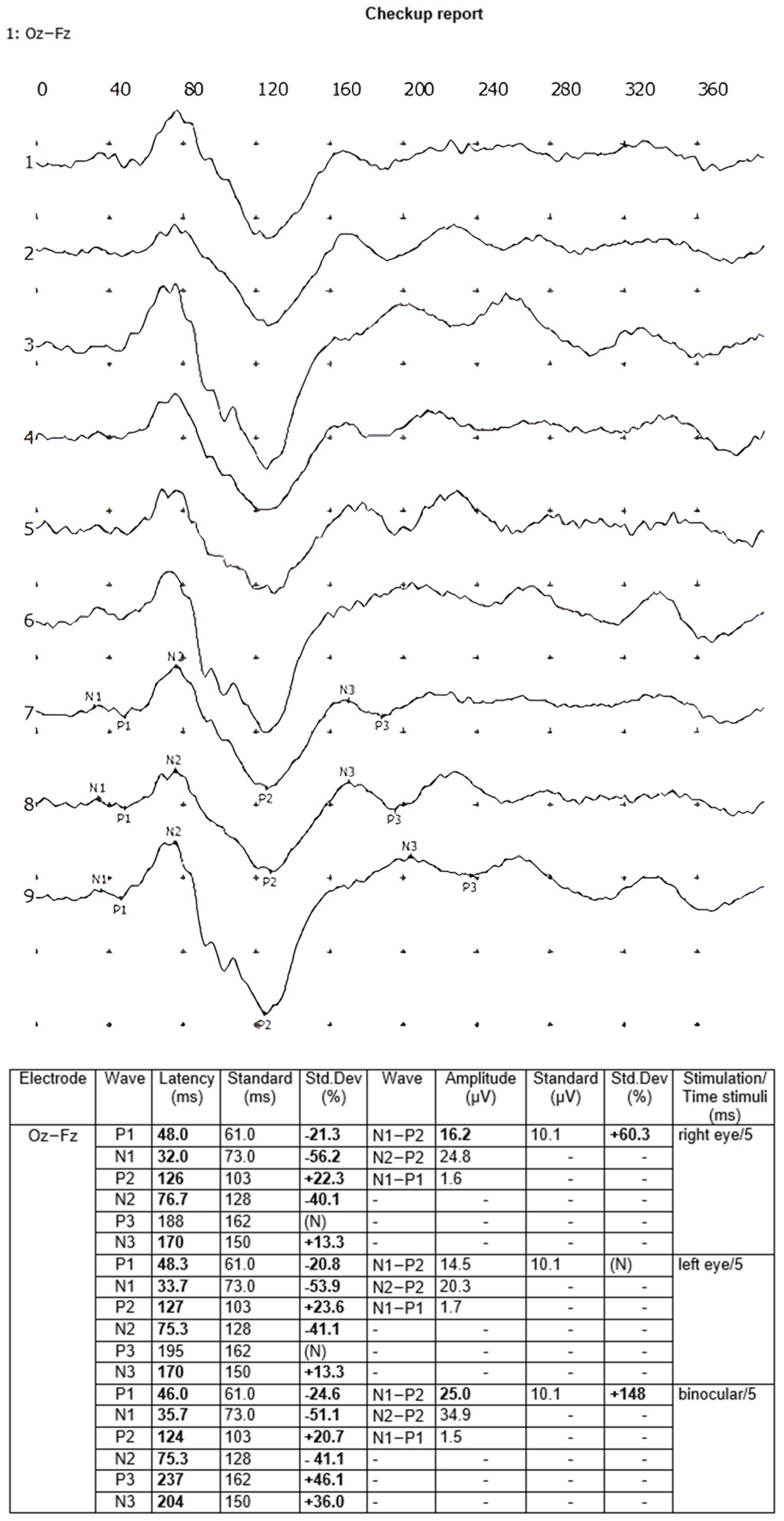
6], the interval between VEP examinations was 24 h, i.e., the recordings were performed at one time of day. After cleansing the scalp with a NUPREP gel and ECOLAB Skinsept Pur, electrodes were bonded to the skin using the TEN20 conductive EEG paste according to the 10–20 international system in the following places: occipital lobe (active/positive electrode Oz), forehead (reference/negative electrode Fz) and right earlobe (ground electrode A2). Each VEP examination was carried out with the flash method using the EEG Neuron-Spectrum-5 equipment and LED goggles emitting red light. Stimulation parameters were selected according to recommendations [
5,
6], i.e., stimulation frequency: 1 Hz; stimulation duration: 5 ms; frequency band of the recorded signal: 2–100 Hz; sampling frequency: 10 kHz. All the VEP examinations were performed in a single-channel Oz-Fz electrode array [
5,
6], i.e., MO-MF, while the stimulation was performed independently in the right eye, in the left eye, and then binocularly, with eighty recordings averaged each time. Each VEP test was prepared twice, and the final averaged recording from the two examinations was analyzed. The following amplitudes—N1-P1, N1-P2, and N2-P2—and latencies—N1, P1, N2, and P2—of the waves were included in the calculations. The VEP reports were generated automatically by the Neuron-Spectrum.NET software 1.0.82.0. An example of a VEP test report is shown in
Figure 1.
Then, to check the value of the scalp-electrode impedance for each of the electrodes, the EEG Neuron-Spectrum-5 amplifier system was used. After the duration of the VEP examination, all the electrodes were cleaned according to the recommendations presented in [
1,
2,
3,
4] and prepared for further tests.
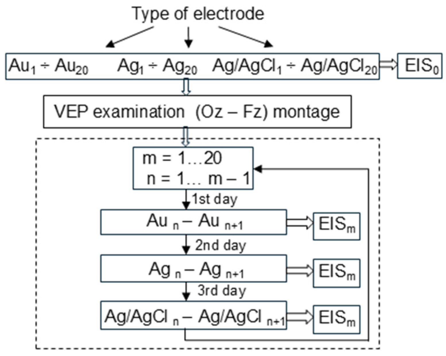
In the next step, the electrochemical impedance spectroscopy (EIS) method was used to check the existence of a relationship between the impedance values of reusable cup electrodes and the number of VEP examinations. To prevent any noises, all measurements were performed within a Faraday cage. After each VEP examination, the electrodes were tested at a frequency range of 0.1–100 Hz and a temperature of 37 °C using the Autolab PGSTAT302N platform, the frequency response analyzer FRA32M, and an electrochemical cell (Metrohm, no. 6.1418.250) with a reference silver/silver chloride electrode (Metrohm 6.0733.100) and a counter platinum electrode (Metrohm 3.109.0790). The TEN20 conductive EEG paste was used in the electrochemical cell. All measurements were performed according to the block diagram presented in
Figure 2.
All new electrodes were subjected to EIS before their first use. Then, the registration of visual evoked potentials was performed. After recording the VEP signals, the electrodes were cleaned, and then each electrode was subjected to EIS analysis.
3. Results
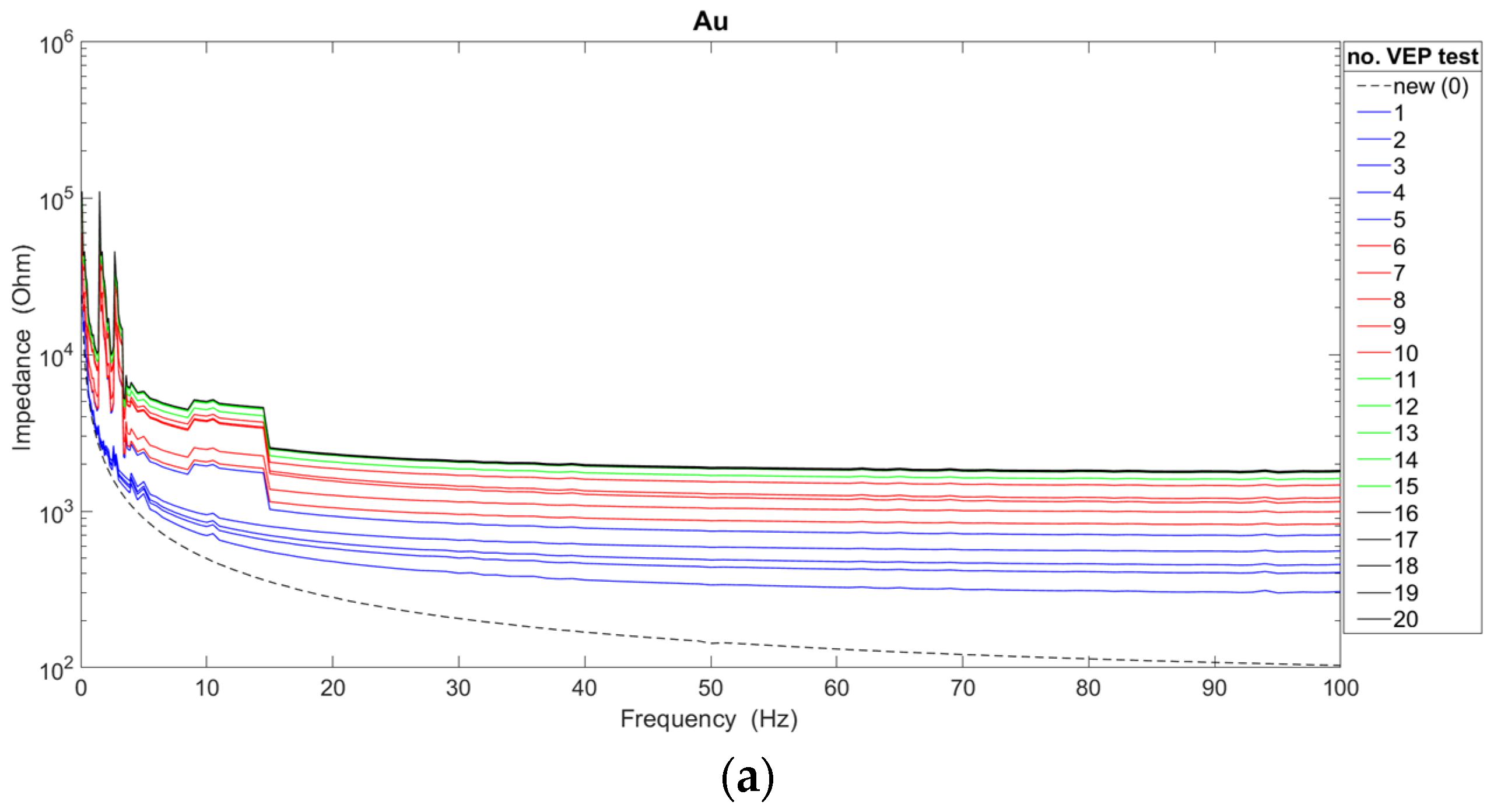
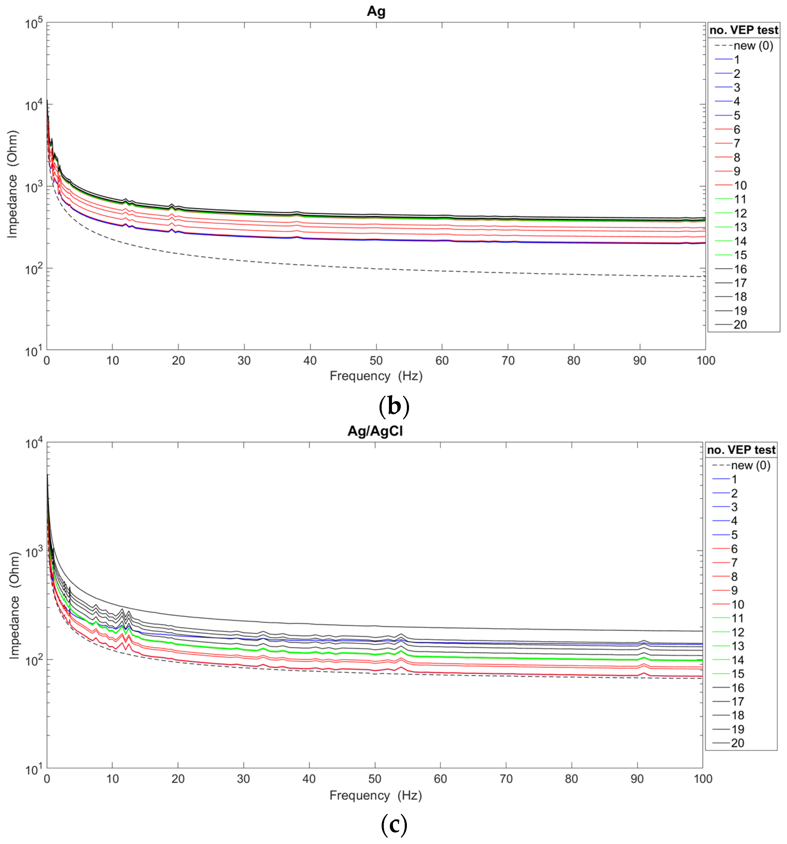
The analysis of the impedance characteristics for each of the cup electrodes after their repeated use is presented in
Figure 3. In order to indicate the significant differences occurring between new and used electrodes, the graphs additionally show the waveforms of characteristics obtained for new electrodes. The average impedance values were calculated based on measurements of twenty electrodes of each type, i.e., gold, silver, silver/silver chloride.
The obtained results confirm the generally known fact that the value of the impedance decreases as the frequency value increases [
17,
18]. Moreover, it can be confirmed that there is a dependence of the impedance value of reusable electrodes on the number of performed VEP examinations. For two types of electrodes (i.e., Ag and Ag/AgCl), the impedance value increases with the number of examinations. In the case of gold electrodes, the impedance decreased significantly after the 11th, 12th, 13th, 14th, and 15th use due to non-uniform degradation of the electrode coating. In fact, gold electrodes are only silver with a gold coating. However, after 16 uses, the impedance increased. Considering the course of all the presented characteristics, the choice of the new Ag/AgCl electrode for recording brain potentials seems to be the most favorable. However, a linear course of characteristics above the frequency of 20 Hz was achieved by Au and Ag electrodes. On the other hand, in the frequency range of up to 10 Hz, the smallest impedance fluctuations were observed for Ag electrodes. The Ag/AgCl electrodes show significant fluctuations, despite achieving the lowest impedance values compared with the other electrodes. Also, for Au electrodes, significant variation in impedance values can be seen. Abrasion of the electrode coating is responsible for the impedance fluctuations. It is worth adding that the characteristics of new electrodes do not show such irregularities. Taking into account the analyses shown in
Figure 3, Ag electrodes should be used for recording brain potentials only in the slow-wave range (i.e., delta and theta activity).
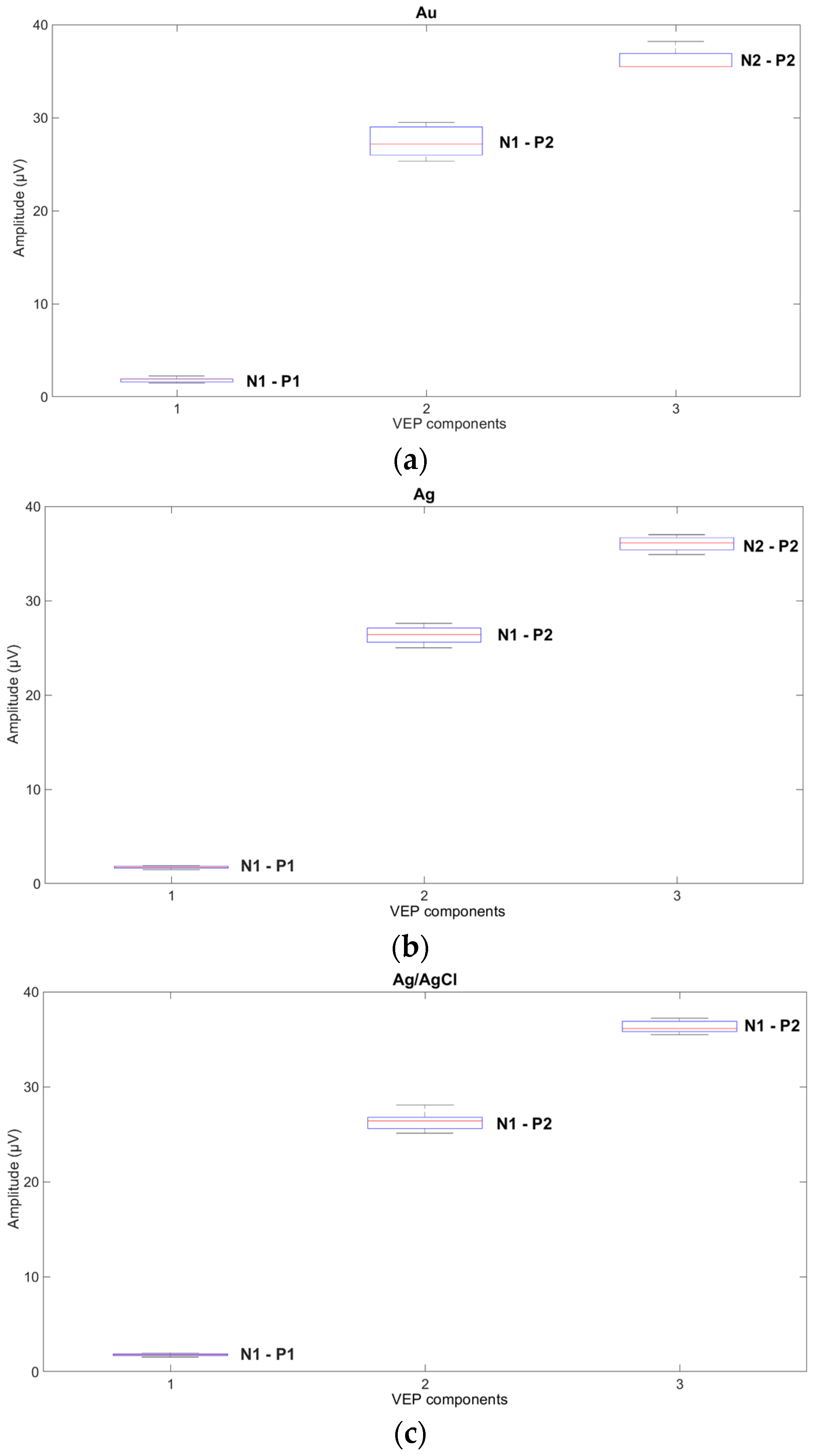
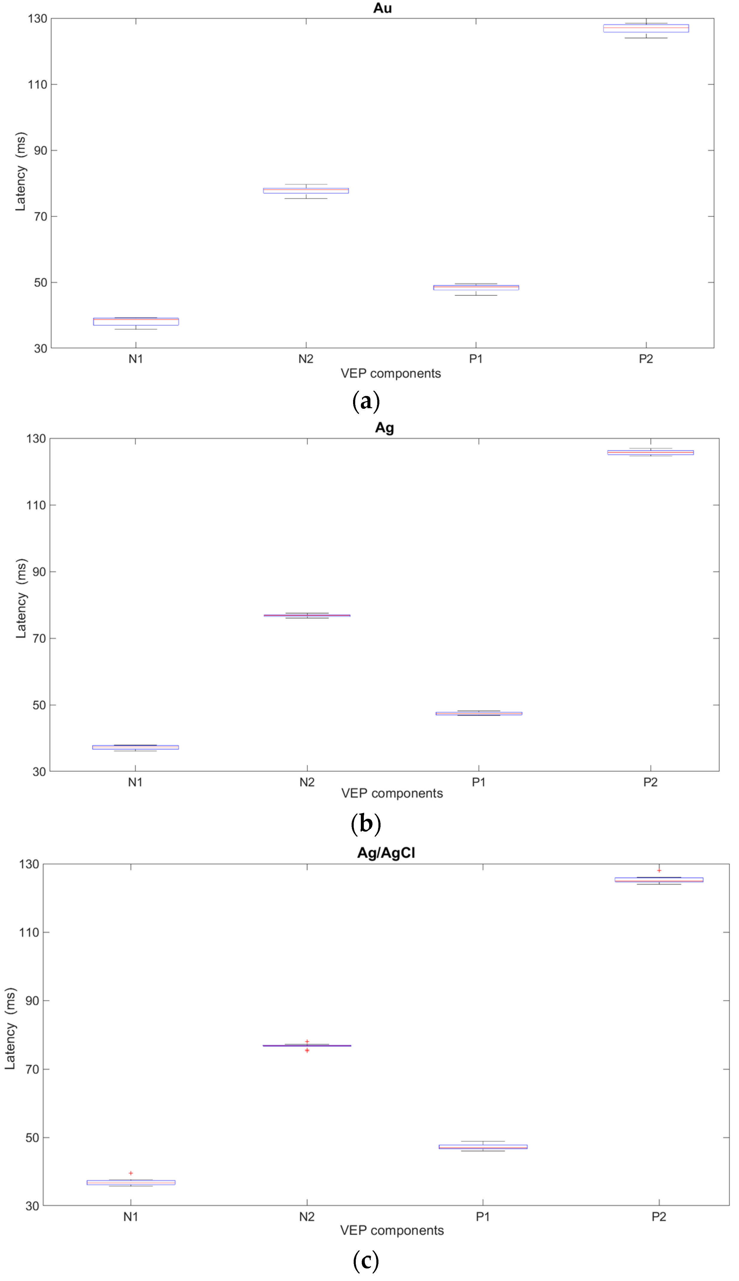
The influence of new cup electrodes on the VEP parameters, i.e., amplitudes and latencies, and the statistical analysis are presented in
Figure 4 and
Table 1 and
Figure 5 and
Table 2 respectively.
Based on the results obtained from the analysis of VEP signals recorded with the new electrodes, variability and significant fluctuations in the values of both the amplitudes and latencies were observed. In the case of new Ag and Ag/AgCl electrodes, the variability in the parameters is comparable but significantly smaller than with Au electrodes. The results suggest that gold electrodes should not be used for recording VEP potentials.
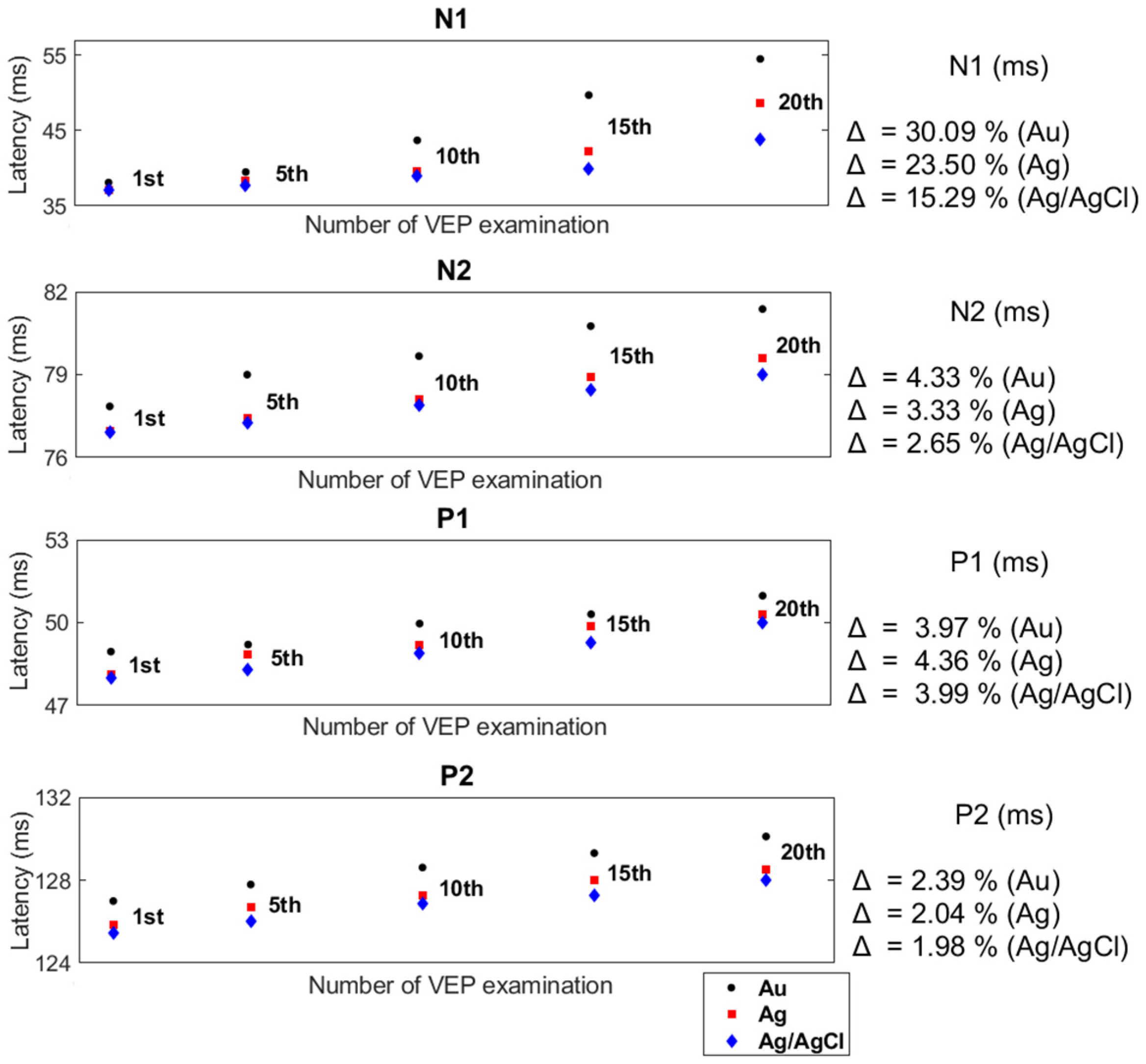
The effect of the number of examinations performed with reusable cup electrodes on the VEP parameters is presented in
Figure 6 and
Figure 7. Based on the results of twenty VEP examinations, obtained for twenty electrodes of each type, i.e., Au, Ag, and Ag/AgCl, the mean values of all the parameters were calculated. Of these figures, the mean values of the VEP after the first, fifth, tenth, fifteenth, and twentieth examinations are shown. Moreover, the differences between the amplitudes and latencies after the first and twentieth examinations are presented using the coefficient Δ.
The presented analyses confirm the existence of a relationship between the number of performed examinations with the same set of reusable cup electrodes and the values of VEP parameters. Each successive use of a reusable cup electrode in a VEP examination affected the values of the latency, causing it to lengthen. In addition, an increase in amplitude values was noted. Despite obtaining similar values for the VEP parameters after the first registration, each subsequent test showed significant differences in the values of the VEP parameters for all electrodes. Comparing the values of the VEP parameters (e.g., N1-P1 and N1) recorded by the electrodes after the first and the twentieth examinations for the Au electrodes showed that there was an increase in the values of the amplitudes of individual components by an average of 61.14% and a prolongation of the latency by 30.09%. In contrast, for the Ag and Ag/AgCl electrodes, the values of the changes in amplitude and latency were, respectively, 52.93%, 23.5%, 49.56%, and 15.29%. The differences between the amplitudes and latencies of the rest of the VEP components were also considerable.
4. Discussion
The presented research confirmed the generally known fact that the electrode impedance decreases with increasing frequency. However, during the tests, an increase in impedance with the subsequent use of the same electrode and also an increase in VEP parameters (i.e., latency and amplitude) were observed. The entire cycle of VEP potential registrations lasted almost two years, which could have affected the obtained values of amplitude and latency. Since the VEP parameters depend on several factors, this author attempted to eliminate most of them.
In clinical practice, the accuracy of the analysis and the interpretation of the obtained results of brain potential examinations depends on the experience and skill of the clinician. When preparing the analysis of the brain potential parameters, it is necessary to take into account a number of factors affecting these parameters, the most important of which are the interindividual differences observed in the same age group of patients and the intrapersonal variability of the range of parameter values [
9]. The analysis of interindividual variability mainly takes into account the patient’s age and health status, as well as gender [
9,
16]. According to [
26], the evoked potentials are stable from about 5 years of age to 60 years of age. The mean peak latency only slows by about one millisecond per decade from the age of 5 until the age of 60. The amplitude and speed of VEPs remain stable until about age 28, after which time the amplitudes begin to attenuate. In the case of gender, the VEP showed a shorter mean latency but a higher mean amplitude for females than males. The age-dependent increase in mean latency was observed in the female group but not in the male group. In contrast, intrapersonal variability in the parameters is not necessarily due to pathological changes and is often observed in healthy individuals [
8]. The reasons for this variability may be due to body temperature, blood pressure, the pH of blood, and bodily fluids. Therefore, all registrations of visual evoked potentials used for the analyses were carried out in a one healthy volunteer, i.e., the author of the paper. To confirm the subject’s good health before starting the VEP recording, his author was tested for demyelinating diseases, diabetes, basic retinal disease, and glaucoma. All these diseases affect visual function, especially retinal disease. In the case of Friedrich’s Ataxia, delayed latency and increased amplitude of the VEP are the most frequent electrophysiological alterations in this pathology [
27]. The results of these tests confirmed the absence of these diseases. To be sure, these tests were repeated after a year.
Moreover, the values of the parameters of some brain potentials, e.g., VEP, depend on the parameters of the stimulating stimulus [
5,
6]. Hence, all VEP registrations prepared for these studies took place for the same value of stimulation parameters due to the dependence of the VEP waveform, amplitudes, and peak times on the parameters of the stimulus. The VEP examinations had the same start time, because the amplitude of brain potentials is influenced not only by the patient’s health, age, gender, inter-individual differences, and antiepileptic and psychotropic drugs. Measurement conditions (i.e., recording times) are also important, because sleepiness and stress affect the VEP amplitude. Sleepiness causes a slowdown in neuronal activity and therefore a decrease in amplitude, while stress increases the amplitude and additionally affects the following latencies: P300, N100, and N400.
Another factor affecting changes in brain potential values discussed in papers [
8,
9,
13,
15,
18] is electrode selection. The main criteria for selecting reusable electrodes for recording brain potentials are the patient’s age and the type of examination [
1,
2,
3,
4,
5,
6,
9]. According to the recommendations presented in [
1,
2,
3,
4,
5,
6], all types of reusable cup electrodes can be used for recording VEPs, i.e., gold, silver, and silver/silver chloride, but for adult subjects, pure silver electrodes are preferred. The purpose of these studies was to test all cup electrodes; therefore, the selection of the electrode type according to the age of the subject was meaningless.
On the other hand, the usage of a particular electrode in the examination is determined by the value of the scalp-electrode impedance, which should not exceed 5 kΩ, and its general technical condition, i.e., no visible changes in the coating color or evidence of mechanical damage [
1,
2,
3,
4,
5,
6,
8,
9,
13]. It should be noticed that during these studies, the scalp–electrode impedance measured with the VEP equipment for all electrodes (i.e., new and used electrodes) was below 5 kΩ. For each of the gold and silver electrodes tested, partial coating-color changes appeared on average after the fifteenth VEP examination. In the case of the Ag/AgCl electrode, tarnishing of the coating occurred after the twentieth test. It is well known that degradation of the electrode coating, especially that occurring with silver and gold electrodes, occurs due to the application of conductive pastes and the cleaning fluids applied after each examination of brain potentials. The frequency properties of each electrode, after another VEP examination, were tested using the electrochemical impedance spectroscopy (EIS) method, which confirmed the results reported in other studies [
13,
15]. When new electrodes were tested, a decrease in impedance values was observed with increasing frequency values. On the other hand, the gradual degradation of the electrode coating following successive VEP recordings has contributed to not only an increase in impedance values after a subsequent examination using the same pair of reusable cup electrodes but also significant fluctuations in the frequency range up to 10 Hz.
Thanks to the VEP registration, in addition to analyzing the course of latency changes, it was possible to observe values of the wave amplitude. As a result of the study, an increase in the amplitude of individual waveforms by an average of 26.42% and a prolongation of latencies by an average of 8.16% were observed by comparing the values of VEP parameters after the first and twentieth recording using reusable cup electrodes. An increase in electrode impedance undoubtedly causes an extension of latency, but the issue of increasing amplitude is debatable. From a technical point of view, the observed increase in electrode impedance, causing an increase in amplitude and an extension of latency, is not correct. In clinical practice, an increased amplitude often occurs regardless of changes in electrode impedance. According to [
28], a larger VEP amplitude indicates stronger cortical activation in response to the visual input. The variability in VEP parameters, and especially in the amplitude, after subsequent stimuli is the result of a change in the sensitivity of the nervous system. A commonly observed phenomenon is either a decrease in reactivity to repeated stimuli (i.e., habituation), or an increase in reactivity to the stimulus (i.e., sensitization). In this paper, the sensitization phenomenon was observed. The sensitization phenomenon can be eliminated by using various types of visual stimuli, i.e., flash and checkerboards, during the one VEP test. However, the results of VEP parameter measurement using different types of stimuli cannot be compared with each other. The analysis of the VEP amplitude is not reliable and should not be taken into account in the quality assessment of cup electrodes.
The results of EIS examinations suggest that reusable electrodes, regardless of the material they are made of (i.e., gold, silver, silver/silver chloride), in the study of evoked brain potentials should be used only once, because the correctness of the examination depends on the latency of the individual VEP components (e.g., P1, N1). However, in the case of EEG data, the multiple use of electrodes is acceptable due to several parameters considered in the final report [
29]. In EEG, the frequency value of individual brain waves refers to selected ranges, i.e., alpha (8–13) Hz, beta (14–30) Hz, theta (4–7.5) Hz, and delta (0.1–3.5) Hz, whereas for VEP, a single value of latency is analyzed. Moreover, for EEG examination, except for amplitude and frequency values, the degree of brain activity symmetry and the degree of brain wave synchrony (i.e., alpha, beta, and theta) or reactivity (e.g., response to eye opening and closing) also have diagnostic significance.
In addition, according to the research presented in [
30] reusable electrodes, even after cleaning, pose a risk of patient cross-contamination owing to the bacterial species present on these electrodes and wires. The solution may be to use waterproof electrodes designed for long-term monitoring (LTM) that can cleaned by autoclaving. However, the problem of electrode impedance changes after each usage would still remain. Alternatives to the reusable cup electrodes commonly used in clinical practice may be the solutions proposed in other studies [
18,
19,
20,
21,
22,
23,
24,
25].
Currently, this author is working on a portable device that checks the degree of degradation of the reusable electrode coatings. The proposed device could be used before recording brain potentials.


