1. Introduction
Rational coal pillar size can not only maintain the roadway’s rock stability but also increase coal production. As mining height increases, the roadways experience multiple mining influences: the mining pressure is strong, the rock’s deformation is large [
1], the narrow coal pillar cannot maintain the stability of the roadway, and the wide coal pillar will cause great waste of coal resources, so how to analyze the coal pillar’s size has become an important problem.
Current research on the mining effects of working face on coal pillars mainly focuses on the following aspects: The first is the cause of the formation of mining-induced mechanics, which often refers to the movement of rock and the redistribution of stress, especially the abutment stress distribution of the coal rock body in front of the working face [
2,
3]. Under the constraints of spatial conditions, different structural modes of the overlying rock formation have been formed, such as the cantilever beam theory, the hinged rock theory, and pre-existing fracture theory [
4], and the theory of masonry beams and key stratum proposed by Qian Minggao, which provides a cornerstone theory for the study of mining pressure in the quarry [
5,
6,
7,
8]. Secondly, the analysis of coal pillar abutment pressure and destruction under the mining influence. The purpose of shortening the coal pillar is achieved by studying the redistribution of abutment pressure [
9,
10], constructing the coal pillar bearing structure, analyzing the distribution of stress and plastic zone in the coal pillar [
11,
12,
13,
14], and avoiding the penetration of high-stress zone and plastic zone. Third, the theoretical and technological development of the surrounding rock stability control Support theory, in addition to the traditional theory of suspension, combined beams, and reinforced arches, also includes the surrounding rock loose circle theory and surrounding rock strengthening theory [
15,
16,
17,
18]. Supporting techniques include crossed anchor support, constant resistance anchor support, partition combined support [
19,
20,
21,
22,
23], etc. Those theories provide technical support for narrow coal pillar stability.
In summary, although research on the retention of coal pillars in digging along the goaf has gradually deepened, basically, it is based on the condition that the coal pillars are affected by mining on one side; research on the optimization of coal pillars in double roadway digging (i.e., the coal pillars are affected by mining on both sides) is still lacking.
Therefore, based on the key stratum’s surrounding rock destruction theory, this article establishes a mechanical model of the mining area structure, analyzes the surrounding rock failure and the coal pillar’s abutment pressure distribution, uses the limit equilibrium method and FLAC3D to analyze the reasonable coal pillar size and the distribution of stress zone and plastic zone of the coal pillar during one-side mining and both-sides mining, and verifies the rationality of the calculated coal pillar width. The engineering application and mine pressure monitoring in the 113 working faces of Jinjitan Coal Mine demonstrate the feasibility of the findings and reference value in engineering applications and in academia.
2. Project Overview
Jinjitan Coal Mine is located in Yulin, Shaanxi Province, China, as shown in
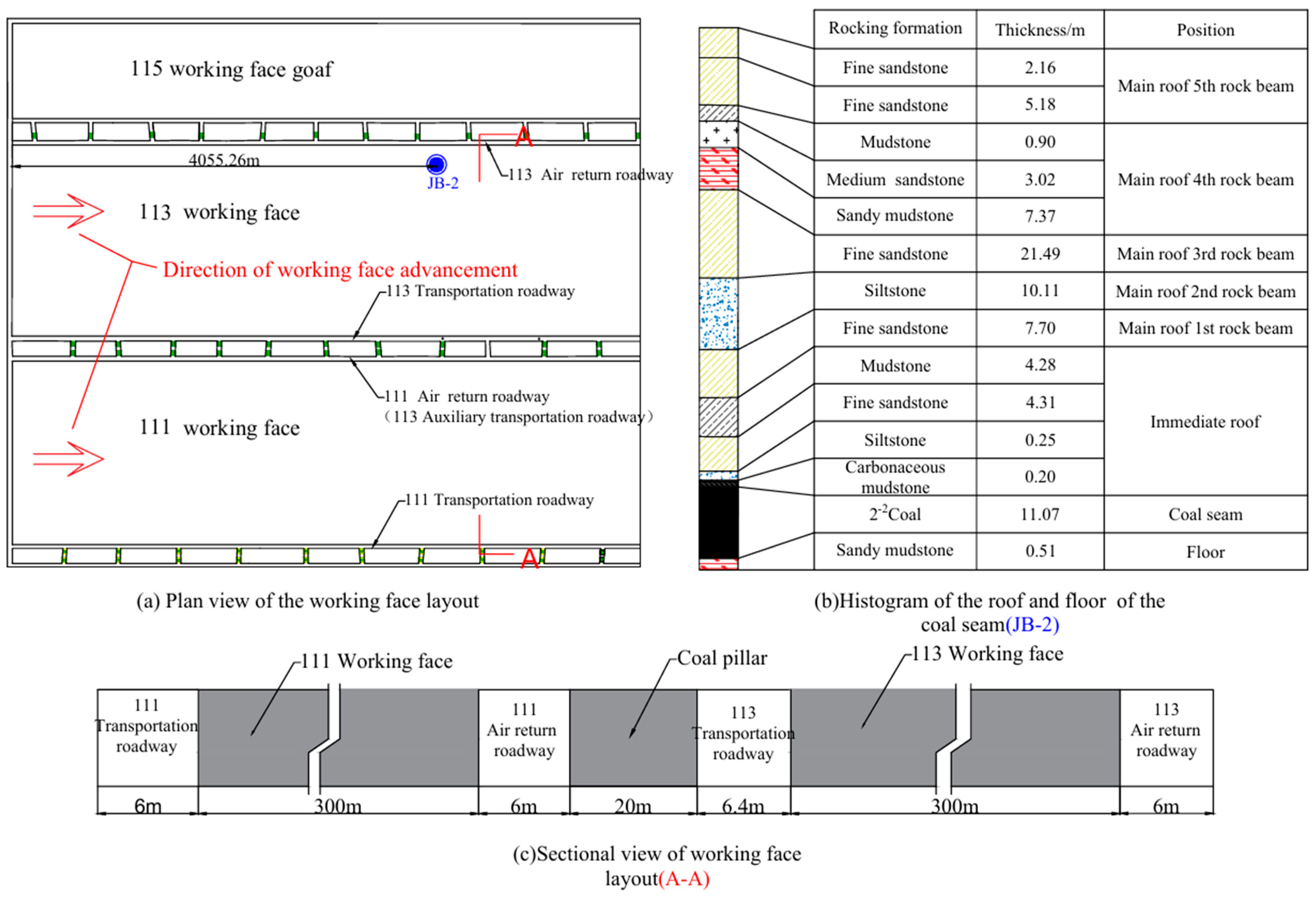
Figure 1; the 12
−2 113 working face (hereinafter referred to as the 113 working face) of Jinjitan Coal Mine is a fully mechanized caving working face with a large mining height. The inclined length of the working face is 300 m, and the walking length is 4847.6 m. The thicknesses of the 2
−2 coal seam are 8.3–12.2 m, with an average of 10.25 m. The spatial layout structure of the 113 working faces is shown in
Figure 2.
The immediate roof is composed of 0.20 m thick carbonaceous mudstone, 0.25 m thick siltstone, 4.31 m thick fine-grained sandstone, and 4.28 m thick mudstone above the coal stratum 2−2. The first rock beam of the main roof is composed of 7.70 m thick fine-grained sandstone, the second rock beam of the main roof is composed of 10.11 m thick siltstone, and the third rock beam is composed of 21.49 m thick fine-grained sandstone (i.e., low key stratum). The total thickness of the fourth to eighth rock beams of the main roof is 57.27 m. The ninth rock beam of the main roof is composed of 28.68 m thick, fine-grained sandstone (i.e., high key stratum).
The 113 working face adopts a double roadway excavation layout, and a 20 m coal pillar was originally left between the 113 transportation roadway and the 113 auxiliary transportation roadway (111 air return roadway). It is considered that there is still room for the existing 20 m coal pillar to be reduced.
3. Analysis of Surrounding Rock Movement Characteristics
When there are multi-layer hard rocks in the surrounding rock, the rock stratum that plays a deterministic role in all or part of the rock activity is called the key stratum, which has a large thickness of the rock stratum, high strength, synchronization of the movement of the rock stratum with the key stratum, and becomes a masonry beam structure as the main body of the bearer after the fracture [
24,
25,
26] and so on. Based on the above characteristics, the third rock beam and the ninth rock beam are initially analyzed as the main body of the key stratum.
After the working face is stabilized in the goaf and the digging of the coal below, the rock stratum is overturned on the axis of the boundary line of the broken area and the fissure development area, and the main roof forms an articulated structure during mining recovery, and the destruction position of the key block B goes deep into the coal wall, and the key block C bites always maintain the transmission of force connection [
27,
28,
29]. Determining the fracture location of the key block and fracture span becomes a key step in analyzing the coal pillar’s abutment pressure.
The key block’s lateral fracture span is the hanging span formed along the lateral direction of the hollow zone after the collapse and stabilization of the main roof rock layer in the working face of the upper section. From the yield line analysis method of the plate, it can be seen that the fracture span of the plate is related to the main roof cycle fracture span and the working face tilted length, which is shown in the calculation formula (1):
In the formula, L1—the span of the main roof periodic fracture, m.
Calculate as formula (2):
In the formula: Lc—upper section of the working face inclined length, take 80 m; H—main roof rock later thickness, m; q1—main roof rock layer unit area loaded, kN/m3; R1—main roof rock layer tensile strength, MPa; the calculation of the L1 is 15.6 m.
Key block B usually breaks at the elastic–plastic intersection location of the lateral coal body, and the calculation formula (3) for the break location of key block B from the edge of the upper section of the mining zone is as follows:
In the formula, h—channel burial depth, m; γB—channel overburden rock average capacity weight, MN/m3; K—stress concentration coefficient; Sm—working face overrun distance, m; MB—maximum thickness of the basic term fracture rock beam, m; the value will be brought into the calculation to obtain X0 = 5.2 m.
After the displacement of the surrounding rock, the stress zone will be redistributed.
In the formula:
H—tunnel buried depth is 263 m;
m—the mining height, taken as 5.8 m;
C0—coal seam bonding force, taken as 5 MPa;
y—the average bulk density of the overlying rockstratum is taken as 0.025 MN/m
3;
k—stress concentration coefficient, taken as 2.8;
λ—coefficient of lateral pressure, taken as 1.8;
φ0—internal friction angle of the coal seam, taken as 36°;
P0—resistance of roadway support, anchor rod support is taken as 0.22 MPa;
θ—internal friction angle of main roof rock;
Sp—abutment pressure peak value. According to the above analysis and calculation, establish the key block structural model as shown in
Figure 3.
4. Calculation of Reasonable Width of Coal Pillar
According to the limit equilibrium theory [
30,
31], with the mining of 111 and 113 working faces, the stress redistribution of surrounding rock is caused, and the stress concentration is caused above the coal pillar. In a certain range of coal pillars, the stress of surrounding rock is still greater than the strength of coal pillars, and the coal body in this area is not completely destroyed, forming a plastic zone. In the central area of the coal pillar, the stress of the surrounding rock is gradually less than the strength of the coal pillar. The stress of the surrounding rock of the coal pillar gradually decreases from the peak value, and the coal body is only. The calculation model for the limit equilibrium is obtained, as shown in
Figure 4.
In order to maintain the stability of the coal pillar, the width of the coal pillar must be greater than the total value of the width of the elastic zone and plastic zone.
The size B of the coal pillar between the roadways is
In the formula: L0—the elastic zone width, m; X0—the plastic zone width on the goaf side, m; R0—the plastic zone width on the roadway side, m.
Plastic zone width on the goaf side:
Plastic zone width on the roadway side:
Elastic zone width in coal pillar:
The calculation parameters are selected as shown in the following table. taken as
C1 = 1.6 MPa,
f1 = 0.4, the overburden load is
p =
Hy = 6.5 MPa. The calculation of each parameter in the formula is shown in
Table 1.
The above determination of coal pillar size did not fully consider the dynamic disturbance effect of tunnel excavation and mining processes on the coal pillar and only considered the abutment pressure coefficient generated by the disturbance. Therefore, we need to introduce the influence factor of excavation and mining to modify the above theoretical formula. In summary, the reasonable width of the coal pillar in the final determination area is as follows:
Based on the layout of the double roadways in the 113 working face, various parameters were substituted, and L = 15.14 m was obtained. Therefore, through theoretical analysis, the maximum width of the coal pillar is 16 m.
5. Numerical Simulation Calculation
5.1. Numerical Simulation Calculation Model Establishment
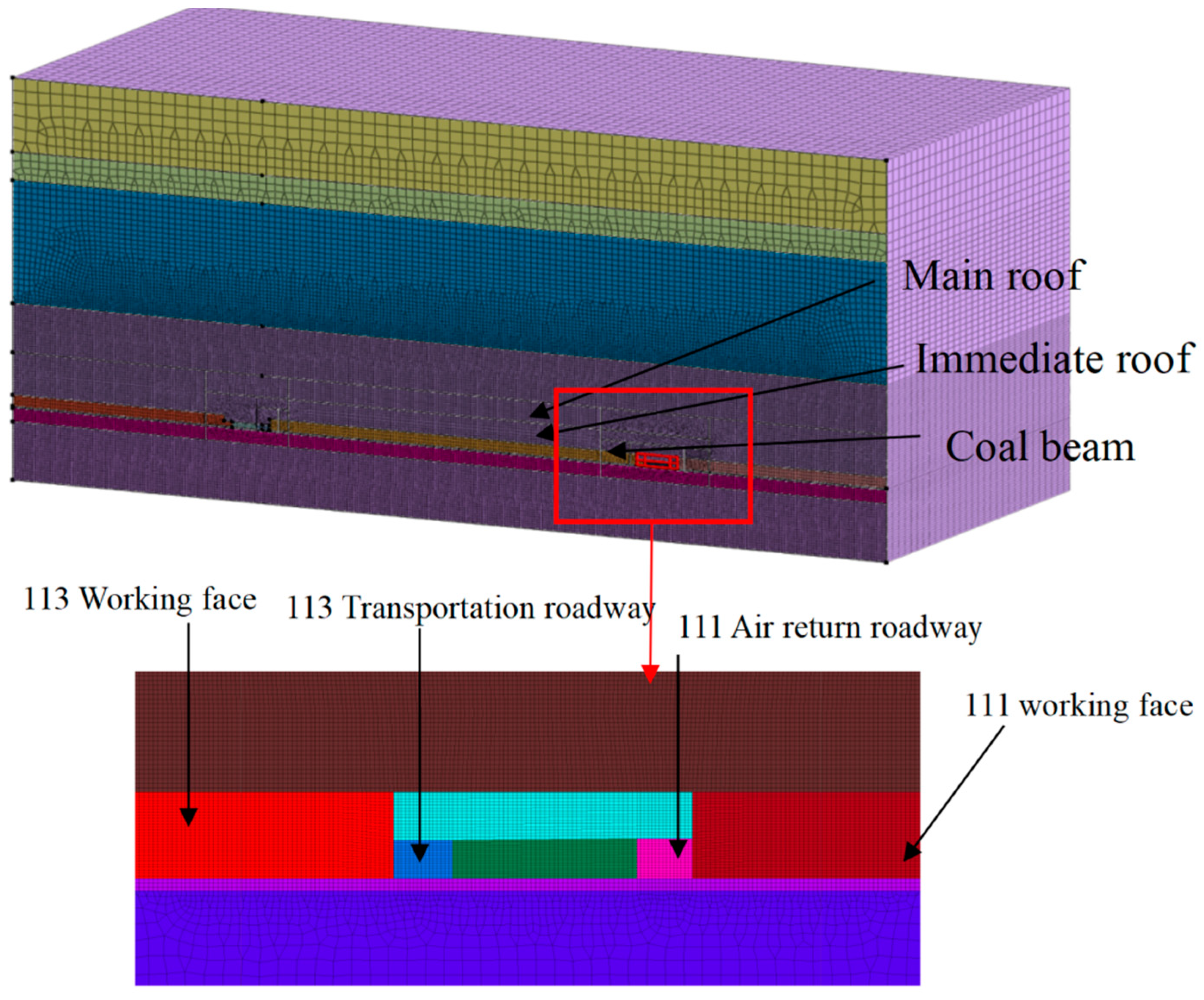
The calculation grid is divided according to the geometry of the model, and considering the regional concentration of the research object, the model includes 113 working faces, 113 transportation roadways, 111 air returnways, 111 working faces, and rock stratum above the roadway and coal pillar. As mentioned at the end of the second section, the mechanical parameters of the rock stratum were experimentally analyzed by coal samples and rock samples, as shown in
Table 2. The model is shown in
Figure 5.
5.2. Distribution of Abutment Pressure and Plastic Zone When the 20 m Pillar Affected by Mining
When the coal pillar width is 20 m, affected by mining on one side of the 113 working faces, the distribution of stress zone and plastic zone in the coal pillar is shown in
Figure 6, counting from 0 m in the 113 transportation roadway, 0–2 m is the low-stress zone and plastic zone, 2–5 m is the high-stress zone and elasticity zone, 5–7 m is the stress-decreasing zone and elasticity zone, 7–18 m is the low-stress zone and elasticity zone, and 18–20 m is the low-stress zone and plasticity zone. After more than a 7 m area in the coal pillar reaches the low-stress zone, the coal pillar can be shortened appropriately and will not affect the stability of the 111 air return roadway.
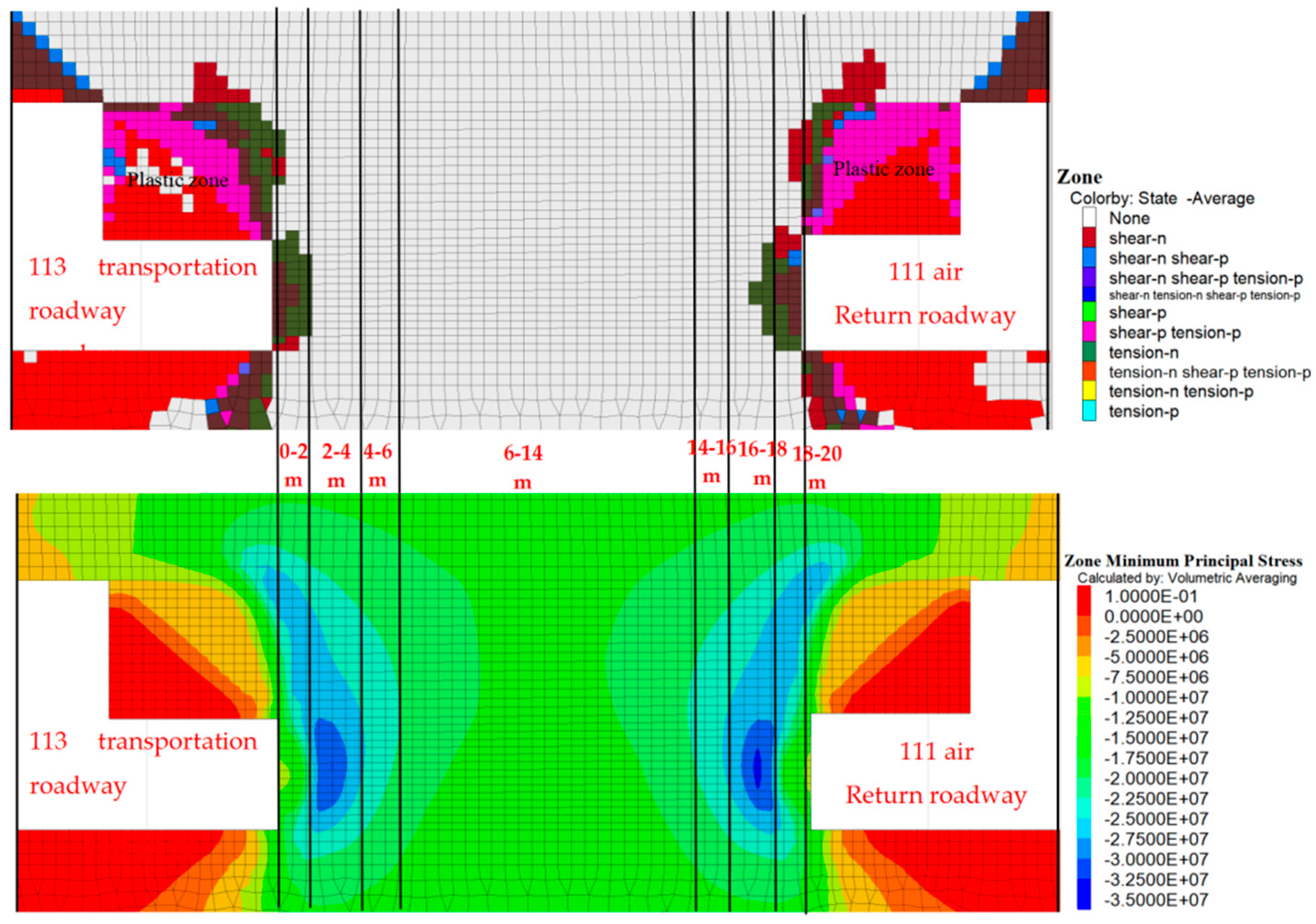
When the coal pillar width is 20 m, affected by the mining on both sides of the 113 working face and 111 working face, the distribution of abutment pressure and plastic zone in the coal pillar is shown in
Figure 7. Counting from 0 m in the 113 transportation lane, 0–2 m and 18–20 m are the low-stress zone and plastic zone, 2–4 m and 16–18 m are the high-stress zone and elasticity zone, 4–6 m and 14–16 m are the stress decreasing zone and elasticity zone, and 6–14 m are the low-stress zone and elasticity zone. There exists an 8 m low-stress zone in the coal pillar, and the shortening of the 20 m coal pillar has almost no effect on the stability of the roadway.
Combined with the above analyses, the existing 20 m coal pillar is large, and there is sufficient space for shortening. When the coal pillar width is reasonable, the coal pillar can play the bearing capacity and is hard to deform and destabilize when digging into the roadway, and it can directly improve coal production.
5.3. Numerical Simulation Calculation of Reasonable Coal Pillar Size
Coal pillars with widths of 5 m, 10 m, 14 m, 16 m, and 18 m were selected as numerical simulation variables, as shown in
Figure 8. The analysis examines the changes in the abutment pressure and plastic zone distribution in the coal pillar during one-side and two-side mining, aiming to determine the optimal size of coal pillars.
5.3.1. Stress Zone and Plastic Zone Distribution in Coal Pillar During Mining on One Side
The distribution of abutment pressure and plastic zone during mining on one side is shown in
Figure 9. According to the result, when the width is 12 m and above, there exists a low-stress zone of 1–8 m in the coal pillar, and the plastic zone is not connected. When the coal pillar width is 12 m and below, the middle and high-stress zone and plastic zone of the coal pillar in the 113 working face and 111 air return roadway are connected, and the stress maximum is more than 30 MPa, which is going against the coal pillar’s stability. In order to ensure the safety of the roadway, the coal pillar size should be more than 13 m.
5.3.2. Stress Zone and Plastic Zone Distribution in Coal Pillar During Mining on Both Sides
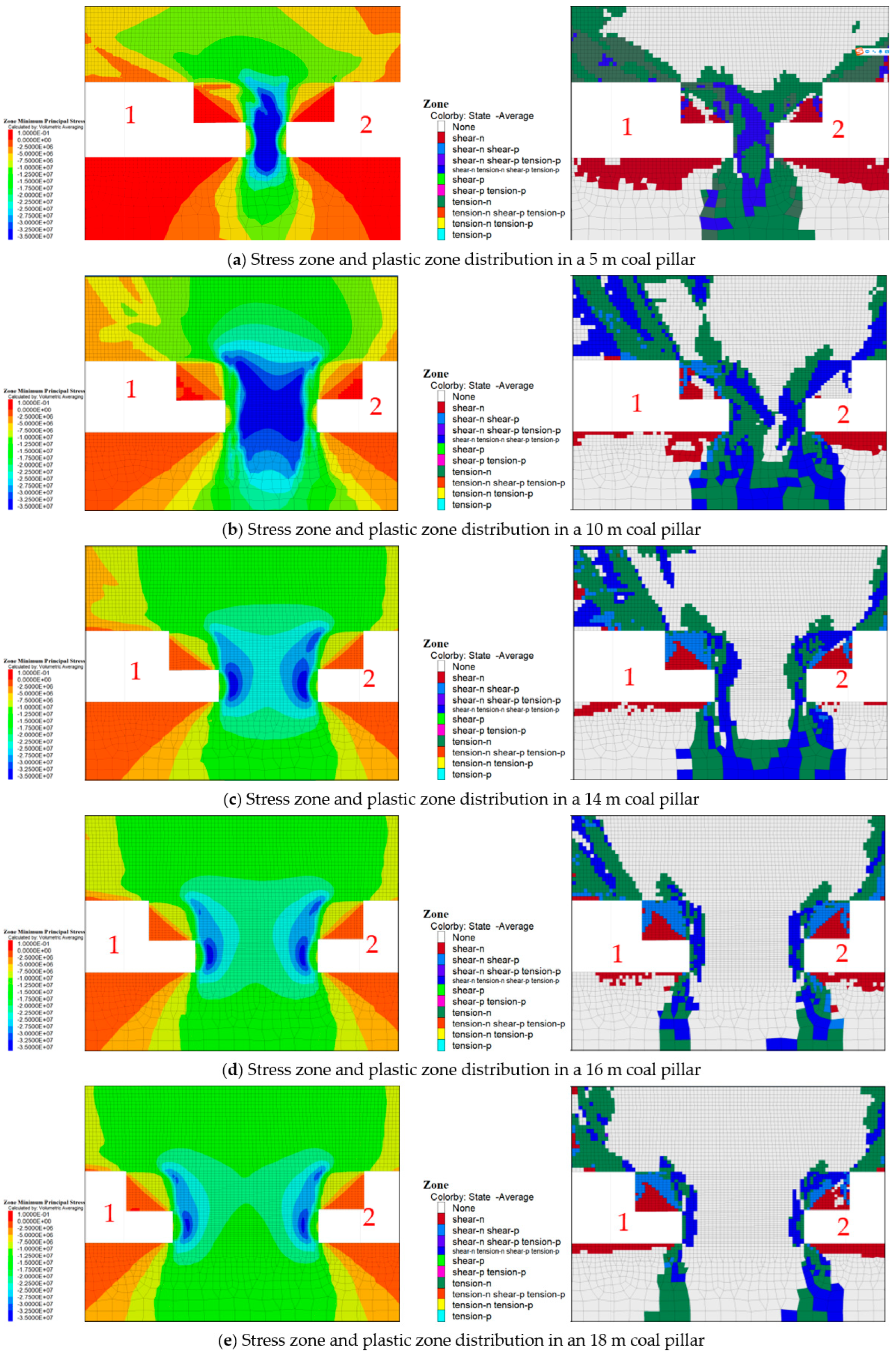
The distribution of abutment pressure and plastic zone in the coal pillar during mining on two sides is shown in
Figure 10. According to the result, when the coal pillar size is 10–13 m, the middle and high-stress zone and plastic zone generated by the recovery mining of 113 and 111 working faces show through the state, and the stress value obviously exceeds 40 MPa, which is bad for the coal pillar’s stability. When the width of the coal pillar increases from 14 m to 16 m, the stress peak area gradually changes from one to two distinguishable areas; the plastic area is not through, and there is a 1–5 m stress relief area in the middle of the coal pillar. The stress peak value has a tendency to decrease gradually, and the stability of the coal pillar is gradually enhanced.
After numerical simulation, it can obtain the distribution of the stress field and plastic zone in the 16 m coal pillar. Compared with a 20 m coal pillar, the peak value of the stress field in the coal pillar is moderate and not connected, and the distribution of the plastic zone is reasonable, as shown in
Figure 11.
Combined with the analysis of the coal pillar’s stress zone and plastic zone distribution during one-side mining and two-side mining, considering the stability of the roadway and the coal utilization rate, comparing with the 20 m coal pillar, the coal pillar’s size is determined to be 16 m.
6. Field Monitoring Plan and Result Analysis
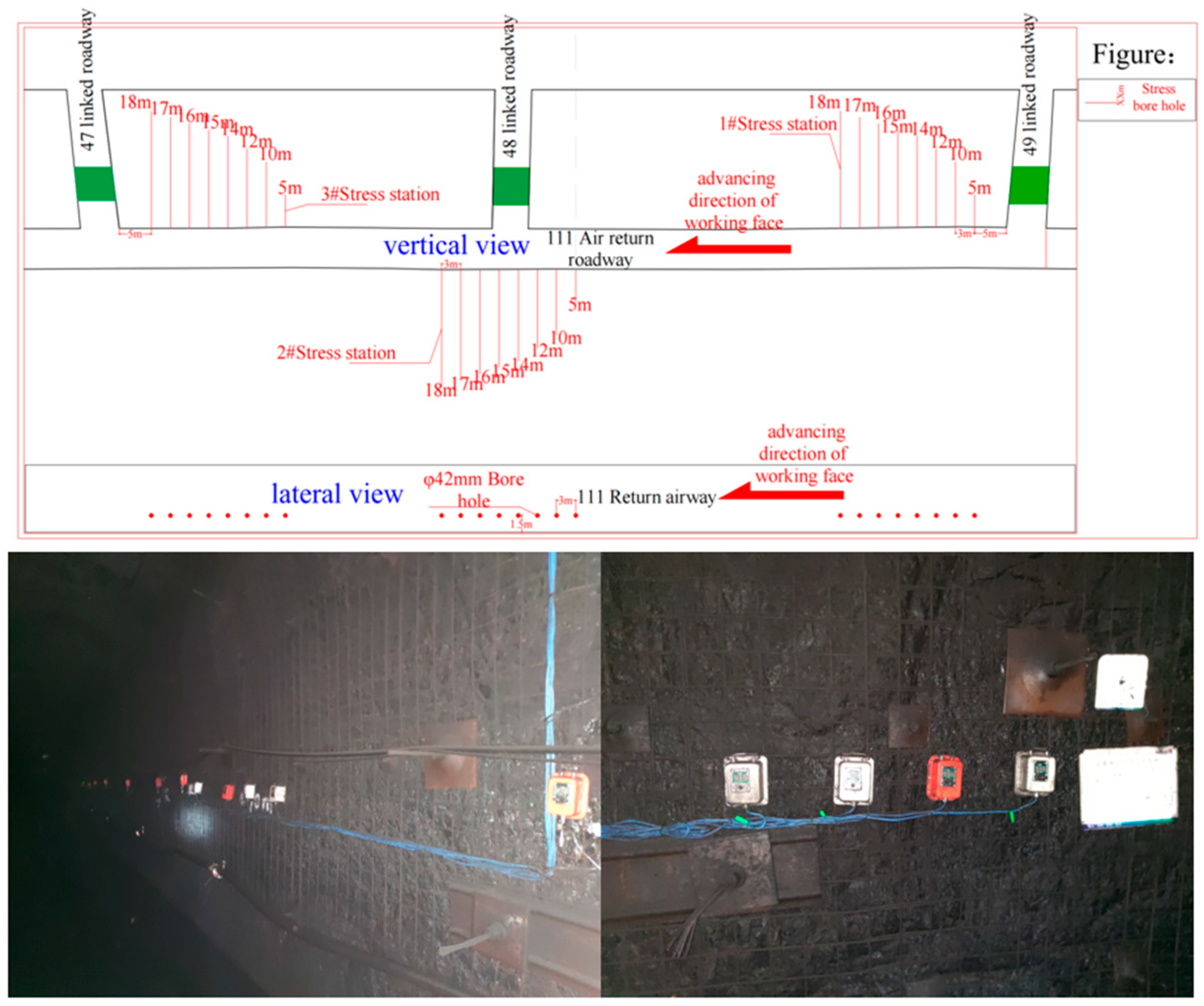
According to the field construction conditions, three stations are placed in the 111 air return roadway; 1# and 3# stations are arranged on the coal pillar side, and two stations are placed on the working face side, with a total of eight holes in each station, with the depths of 5 m, 10 m, 12 m, 14 m, 15 m, 16 m, 17 m, and 18 m, respectively, and the specific arrangement is shown in
Figure 12.
According to the results of
Figure 13, when the station was 30 m from the working face when the mining pressure began to show, the station was 20 m from the working face when the stress began to rise dramatically, and the depth of 16 m drilling stress peak was between 8 and 12 MPa. Compared to the depth of less than 16 m drilling stress, the 16 m drilling stress peak is small, and the drilling stresses that are deeper than 16 m are not much different from the stresses in 16 m, indicating that the coal pillar is 16 m, the roadway can still maintain stability, and compared to the large coal pillar, it can again improve the resource utilization rate.
7. Conclusions
This study fully analyzed the impact of surrounding rock disturbance caused by double-roadway digging and verified it by theoretical analysis. By using numerical simulation and field monitoring, the results showed that a 16 m coal pillar could maintain roadway stability under the condition of improving the efficiency of the double-roadway digging and improving the utilization rate of the coal resources compared with the 20 m pillar. This provides a reliable reference for the optimization of large coal pillars under multiple disturbances in coal mines with similar working conditions in other countries around the world.
- (1)
For solving large coal pillar shortening difficulty under the disturbance of mining on both sides, this research adopts the method of theoretical analysis–numerical simulation–site monitoring, based on key stratum theory, builds the structural mechanics model, reasonably analyzes the displacement of the surrounding rock, comes up with the state of distribution of supporting pressure, and applies the method of limit equilibrium to obtain the theoretical width of the coal pillar is 16 m. The double roadway excavation is relatively small, and the position of the roadway is located in the high-stress peak area. Reasonably, reducing the coal pillar size is the best choice.
- (2)
FLAC3D numerical simulation is used to verify the results, which show that when the coal pillar width is 16 m, the stress of the coal pillar is lower, and the range of the plastic zone is smaller under the condition of mining on one side, and the stress peak is reduced under the condition of mining on both sides, and there exists a stress buffer zone of 1–5 m, and the elastic zone width is large. Therefore, compared with the original 20 m coal pillar, the 16 m coal pillar can meet the requirements of safety and efficiency.
- (3)
Combined with field monitoring results, it is concluded that the range of mining pressure manifestation is 30 m, and when the distance of the monitoring station from the working face is less than 20 m, the internal stress of the coal pillar increases sharply, and the peak stress of the 16 m deep borehole is less than 10 MPa, indicates the 16 m coal pillar’s rationality.
In summary, this study gradually deepens and advances from the above three aspects, verifies the feasibility of a 16 m small coal pillar, provides the theoretical basis and engineering support for the optimization of double-roadway way excavation large coal pillars, and provides reliable examples for coal mines with similar conditions. However, there are still shortcomings. Limited by geological conditions, the stratum and surrounding rock conditions of Jinjitan Coal Mine are good, and this study did not consider the complex soft rock geological conditions. The production conditions of Jinjitan Coal Mine are good, and it is less affected by gas and mine earthquakes. This coal pillar optimization does not include the possible gas explosion and mine earthquake in the research scope. So, there is still much room for improvement.
Author Contributions
Methodology, L.P.; software, M.H.; validation, L.P. and K.G.; formal analysis, K.G.; investigation, L.P.; data curation, K.G.; writing—review and editing, K.G.; supervision, M.H.; project administration, L.P.; funding acquisition, L.P. All authors have read and agreed to the published version of the manuscript.
Funding
This research was funded by the National Natural Science Foundation of China (Grant Number 51674058).
Institutional Review Board Statement
Not applicable.
Informed Consent Statement
Not applicable.
Data Availability Statement
The data presented in this study are available on request from the corresponding author. The data are not publicly available due to the confidentiality of the project involved.
Acknowledgments
We thank the anonymous reviewers for their constructive feedback.
Conflicts of Interest
The authors declare no conflicts of interest.
References
- Ma, Z.; Li, S.; Zhao, X. Energy accumulation characteristics and induced rockburst mechanism of roadway surrounding rock under multiple mining disturbances: A case study. Sustainability 2023, 15, 9595. [Google Scholar] [CrossRef]
- Xie, H.P.; Zhou, H.W.; Liu, J.F.; Xue, D.J. Mining-induced mechanical behavior in coal seams under different mining layouts. J. China Coal Soc. 2011, 36, 1067–1074. [Google Scholar]
- Li, L.; Zhang, A.B.; Zhang, C.L. Study on the abutment pressure and advanced support of driving roadway along goaf of isolated mining face. Adv. Mater. Res. 2014, 3226, 2533–2538. [Google Scholar] [CrossRef]
- Mortazavi, N.; Ziaei-Rad, S. Energy harvesting from vibrations of a beam under mass passage by arc-shaped auxetic cantilever beams. Eur. J. Mech. A/Solids 2025, 109, 105432. [Google Scholar] [CrossRef]
- Ma, K.; Yuan, F.; Wang, H.; Zhang, Z.; Sun, X.; Peng, Y.; Wang, H. Fracture mechanism of roof key strata in Dongjiahe coal mine using microseismic moment tensor. Geomat. Nat. Hazards Risk 2021, 12, 1467–1487. [Google Scholar] [CrossRef]
- Liu, C.; Li, H.; Mitri, H. Effect of strata conditions on shield pressure and surface subsidence at a longwall top coal caving working face. Rock Mech. Rock Eng. 2019, 52, 1523–1537. [Google Scholar] [CrossRef]
- Wang, F.; Chen, T.; Ma, B.; Chen, D. Formation mechanism of stress arch during longwall mining based on key strata theory. Energy Explor. Exploit. 2022, 40, 816–833. [Google Scholar] [CrossRef]
- Wang, Q.; Jiang, Z.; Jiang, B.; He, M.; Yang, J.; Xue, H. Ground control method of using roof cutting pressure release and energy-absorbing reinforcement for roadway with extra-thick hard roof. Rock Mech. Rock Eng. 2023, 56, 7197–7215. [Google Scholar] [CrossRef]
- Wang, T.; Wei, Y. Evolution law of stress-deformation-permeability of coal pillar along gob and its effect on stability of coal pillar. IOP Conf. Series: Earth Environ. Sci. 2021, 859, 012050. [Google Scholar] [CrossRef]
- Ren, J.; Zhao, Y.; Wang, W.; Guo, J.; Sun, Z.; Liu, S. Optimal design of a protective coal pillar with a buried pipeline in a thick loose layer in western china: Methodology and case study. Rock Mech. Rock Eng. 2023, 56, 2879–2896. [Google Scholar] [CrossRef]
- Liu, S.; Bai, J.; Wang, X.; Wang, G.; Wu, B.; Li, Y.; Zhao, J. Study on the stability of coal pillars under the disturbance of repeated mining in a double-roadway layout system. Front. Earth Sci. 2021, 9, 754747. [Google Scholar] [CrossRef]
- Khanal, M.; Adhikary, D.; Jayasundara, C.; Balusu, R. Numerical study of mine site specific multiseam mining and its impact on surface subsidence and chain pillar stress. Geotech. Geol. Eng. 2016, 34, 217–235. [Google Scholar] [CrossRef]
- Zhu, Z.; Wu, Y.; Liang, Z. Mining-induced stress and ground pressure behavior characteristics in mining a thick coal seam with hard roofs. Front. Earth Sci. 2022, 10, 843191. [Google Scholar] [CrossRef]
- Li, X.; Gong, S.; Dou, L.; Chai, Y. Detection of stress redistribution in a complex isolated coal pillar with active SVT technology. Arab. J. Geosci. 2020, 13, 965. [Google Scholar] [CrossRef]
- Reed, G.; Mctyer, K.; Frith, R. An assessment of coal pillar system stability criteria based on a mechanistic evaluation of the inter action between coal pillars and the overburden. Int. J. Min. Sci. Technol. 2017, 27, 9–15. [Google Scholar] [CrossRef]
- Zhang, Q.; Jiang, B.-S.; Wang, S.-L.; Ge, X.-R.; Zhang, H.-Q. Elasto-plastic analysis of a circular opening in strain-softening rock mass. Int. J. Rock Mech. Min. Sci. 2012, 50, 38–46. [Google Scholar] [CrossRef]
- Park, K.-H.; Kim, Y.-J. Analytical solution for a circular opening in an elastic–brittle–plastic rock. Int. J. Rock Mech. Min. Sci. 2006, 43, 616–622. [Google Scholar] [CrossRef]
- Sharan, S.K. Elastic–brittle–plastic analysis of circular openings in hoek brown media. Int. J. Rock Mech. Min. Sci. 2003, 40, 817–824. [Google Scholar] [CrossRef]
- Zang, C.; Chen, M.; Zhang, G.; Wang, K.; Gu, D. Research on the failure process and stability control technology in a deep roadway: Numerical simulation and field test. Energy Sci. Eng. 2020, 8, 2297–2310. [Google Scholar] [CrossRef]
- Li, G.; Ma, F.; Guo, J.; Zhao, H.; Liu, G. Study on deformation failure mechanism and support technology of deep soft rock roadway. Eng. Geol. 2020, 264, 105262. [Google Scholar] [CrossRef]
- He, M.; Gong, W.; Wang, J.; Qi, P.; Tao, Z.; Du, S.; Peng, Y. Development of a novel energy-absorbing bolt with extraordinarily large elongation and constant resistance. Int. J. Rock Mech. Min. Sci. 2014, 67, 29–42. [Google Scholar] [CrossRef]
- Kang, H.; Lv, H.; Zhang, X.; Gao, F.; Wu, Z.; Wang, Z. Evaluation of the ground response of a pre-driven longwall recovery room supported by concrete cribs. Rock Mech. Rock Eng. 2016, 49, 1025–1040. [Google Scholar] [CrossRef]
- Tan, X.; Chen, W.; Liu, H.; Chan, A.H.C.; Tian, H.; Meng, X.; Wang, F.; Deng, X. A combined supporting system based on foamed concrete and u-shaped steel for underground coal mine roadways undergoing large deformations. Tunn. Undergr. Space Technol. 2017, 68, 196–210. [Google Scholar] [CrossRef]
- Cheng, G.; Yang, T.; Liu, H.; Wei, L.; Zhao, Y.; Liu, Y.; Qian, J. Characteristics of stratum movement induced by downward longwall mining activities in middle-distance multi-seam. Int. J. Rock Mech. Min. Sci. 2020, 136, 104517. [Google Scholar] [CrossRef]
- Majdi, A.; Hassani, F.P.; Nasiri, M.Y. Prediction of the height of destressed zone above the mined panel roof in longwall coal mining. Int. J. Coal Geol. 2012, 98, 62–72. [Google Scholar] [CrossRef]
- Xie, J.-L.; Xu, J.-L. Effect of key stratum on the mining abutment pressure of a coal seam. Geosci. J. 2017, 21, 267–276. [Google Scholar] [CrossRef]
- Wen, Z.; Tan, Y.; Han, Z.; Meng, F. Construction of time-space structure model of deep stope and stability analysis. Pol. J. Environ. Stud. 2016, 25, 2633–2639. [Google Scholar] [CrossRef]
- Wu, Q.; Jiang, J.; Wu, Q.; Xue, Y.; Kong, P.; Gong, B. Study on the fracture of hard and thick sandstone and the distribution characteristics of microseismic activity. Geotech. Geol. Eng. 2018, 36, 3357–3373. [Google Scholar] [CrossRef]
- Cheng, G.; Chen, C.; Li, L.; Zhu, W.; Yang, T.; Dai, F.; Ren, B. Numerical modelling of strata movement at footwall induced by underground mining. Int. J. Rock Mech. Min. Sci. 2018, 108, 142–156. [Google Scholar] [CrossRef]
- Chen, S.; Wang, H.; Wang, H.; Guo, W.; Li, X. Strip coal pillar design based on estimated surface subsidence in eastern China. Rock Mech. Rock Eng. 2016, 49, 3829–3838. [Google Scholar]
- Cui, X.; Wang, J.; Liu, Y. Prediction of progressive surface subsidence above longwall coal mining using a time function. Int. J. Rock Mech. Min. Sci. 2001, 38, 1057–1063. [Google Scholar] [CrossRef]
| Disclaimer/Publisher’s Note: The statements, opinions and data contained in all publications are solely those of the individual author(s) and contributor(s) and not of MDPI and/or the editor(s). MDPI and/or the editor(s) disclaim responsibility for any injury to people or property resulting from any ideas, methods, instructions or products referred to in the content. |
© 2024 by the authors. Licensee MDPI, Basel, Switzerland. This article is an open access article distributed under the terms and conditions of the Creative Commons Attribution (CC BY) license (https://creativecommons.org/licenses/by/4.0/).


