Article

Structural Designing of Supersonic Swirling Devices Based on Computational Fluid Dynamics Theory

1
School of Petroleum Engineering, Chongqing University of Science and Technology, Chongqing 401331, China
2
School of Safety Science and Engineering, Chongqing University of Science and Technology, Chongqing 401331, China
*
Authors to whom correspondence should be addressed.
Appl. Sci. 2025, 15(1), 151; https://doi.org/10.3390/app15010151
Submission received: 30 November 2024 / Revised: 24 December 2024 / Accepted: 25 December 2024 / Published: 27 December 2024

Abstract

:
The supersonic swirling device is a new apparatus that can be used for natural-gas liquefaction. The structure of the supersonic swirling device has an important impact on the liquefaction efficiency. Therefore, this study presents a structural design method for supersonic cyclones based on CFD theory. Using the production parameters of a liquefied natural gas (LNG) peak-shaving station as the study case, a detailed design and design comparison of each part of the supersonic swirling separator are carried out. An optimum LNG supersonic swirling separator design was obtained. To ensure that the designed supersonic swirling separator achieved better liquefaction effectiveness, it was ascertained that no large shockwaves were generated in the de Laval nozzle, the pressure loss on the swirler was small, and the swirler was able to produce a large centripetal acceleration. The opening angle of the diffuser and the length of the straight tube were designed considering the location at which normal shockwaves were generated. The location at which shockwaves are generated and the friction effect are important parameters that determine the gap size. With this design guidance, the optimal structural dimensions of the supersonic swirling device for a given processing capacity were determined as follows: a swirler with six vanes and an 8 mm wide channel; a 10D-long straight tube, an opening angle of 20° between the straight tube and the divergent section, and a gap size of 2 mm. Compared with “Twister II”, the new device has better liquefaction efficiency.

1. Introduction

Liquefied natural gas (LNG) is a liquid product formed by the separation of preprocessed, qualified natural gas after compression and cooling to its boiling point. LNG is an advanced clean energy source, and under standard conditions, its volume is approximately 1/625 times that of the same amount of gaseous natural gas [1,2]. Supersonic swirl separation is the most widely used technique for the purification and liquefaction of natural gas [3,4,5,6]. A typical supersonic swirling separator consists of swirling vanes, a supersonic nozzle, a swirling separation section, and a diffuser, as shown in Figure 1 [7]. This technique combines the expansion and cooling of gases to perform centrifugal separation in a single compact device. The technique is highly advantageous because of its small footprint, simple structure, high efficiency, low energy consumption, environmental friendliness, and absence of any rotating part in the device. Thus, it has significant application prospects [8]. The liquefaction efficiency of supersonic cyclonic separators is closely related to their structural designs.
At present, the structural design of supersonic swirling separators mainly focuses on the profile, location, and structure of the swirling generators and the cross-section of the flow channels. The nozzle design consists of four parts: the inlet stabilization section, de Laval nozzle, flow-conditioning straight tube section, and diffuser. The de Laval nozzle consists of three regions: convergent section, throat, and divergent section. Commonly used methods to design the convergent section include the Witoszynski curve, Batchelor–Shaw curve, bicubic curve, quintic curve, and area ratio methods [9]. In the design of supersonic separator tubes, the Witoszynski curve and area ratio are the most frequently used methods, as they yield good results. The commonly used methods to design the divergent section include the characteristic line method, Foelsch method, Lao method, area ratio method, and equal-slope method. Because the area ratio method is based on gas dynamics theory, it has good application performance; therefore, it is a widely used method in the design of divergent sections. The equal-slope method is another widely used method because its design and calculation are simple, and profiles are easy to fabricate and have good practical application performance. Jiang et al. [10] studied the relationship between the length and the outlet diameter of the divergent section, and found that the separation tube should be installed at the back of the de Laval tube. The diffuser compresses the remaining natural gas that has not been liquefied by increasing its pressure and temperature and transports it into the natural gas pipeline. Based on both simulation and experimental studies conducted on the above design methods, researchers have shown that the Witoszynski curve design is the most suitable for convergent sections, and both the area ratio and equal-slope methods are suitable for divergent sections [11]. In addition, it was found that the geometric design of each tube section had a significant effect on the cooling and separation effectiveness of the device, and that the system was required to be designed based on parameters such as the flow, pressure, and temperature of the object to be processed. However, owing to the assumptions and empirical values associated with the design methods currently used, there is a difference between the actual operational performance and the design performance of supersonic swirling separators. Therefore, a design method that is more accurate is required.
With the rapid development of computer technology, the field of rotational flow mechanics has achieved significant progress and maturity. Innovations in computer technology have not only provided more powerful computational and analytical tools for the study of rotational flow mechanics but have also driven comprehensive development in the areas of theory, experimentation, and application within this field [12,13]. Therefore, many researchers have performed numerical simulation studies on the supersonic swirl separation process, conducted in-depth analyses of the mechanism of separation, and attained structural optimization. For example, Malyshkina [14] proposed a procedure for investigating the efficiency of natural gas purification in a supersonic separator. Wen et al. [15] analyzed the effect of the nozzle geometry on the swirling separation. Vlasenko et al. [16] analyzed the effect of the swirling method and separation insert gap on the operational efficiency. Wu et al. [17] proposed a flow model and a condensation model for the supersonic nozzle, and analyzed the use of a supersonic nozzle for the condensation and separation performance of H2 and CO2 from supercritical water gasification products (SCWGP). Chen et al. [18] analyzed the effect of wall thermal condition on the nonequilibrium condensation of CO2 in supersonic flows. However, research results show that in the separation process using conventional supersonic separators, the divergent section of the nozzle before swirling is prone to generating shockwaves, the low-temperature section is short, and the cooling effect is not ideal. In addition, swirling occurs at subsonic speeds, and therefore, its efficiency is low [7,19]. Therefore, it is necessary to further optimize the structure of the supersonic swirling device. Based on the expansion and spontaneous condensation mechanisms, this study uses numerical simulation to optimize the structure of a supersonic swirl separation device for natural gas liquefaction.

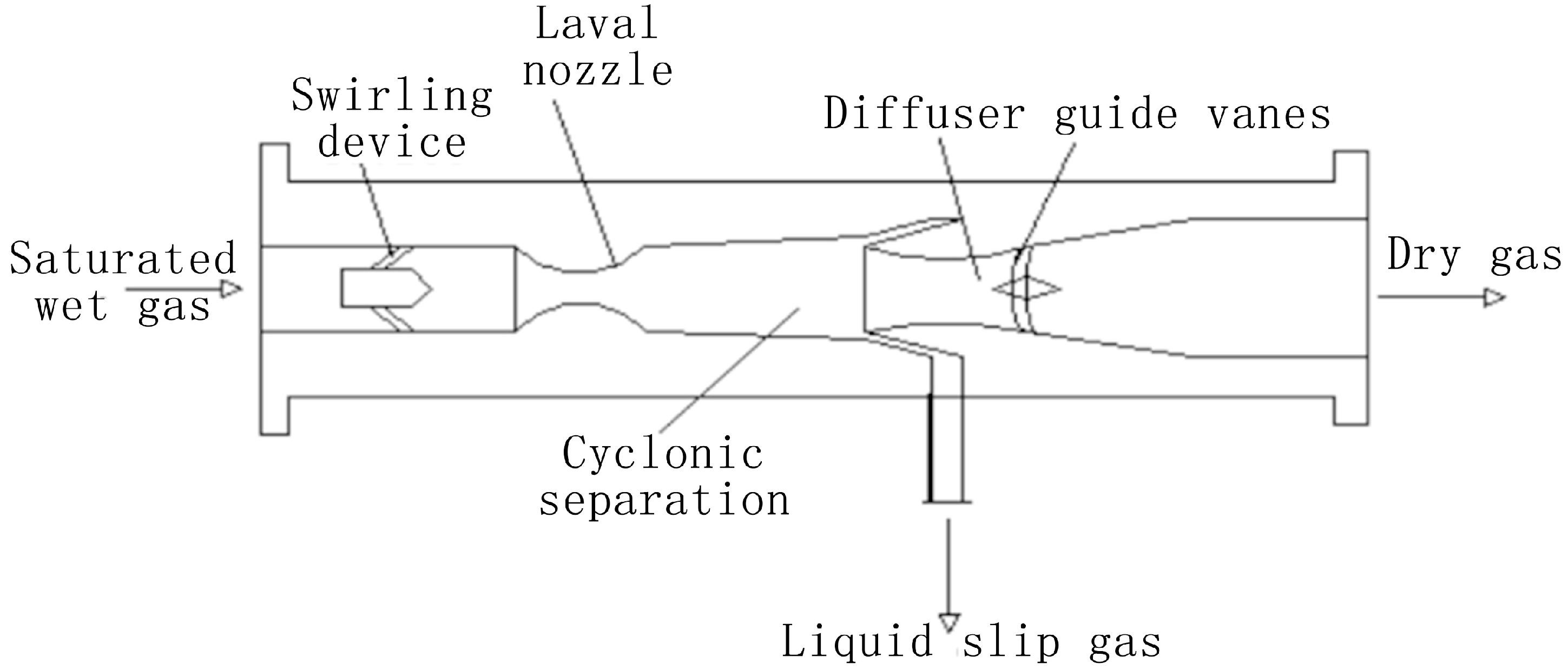
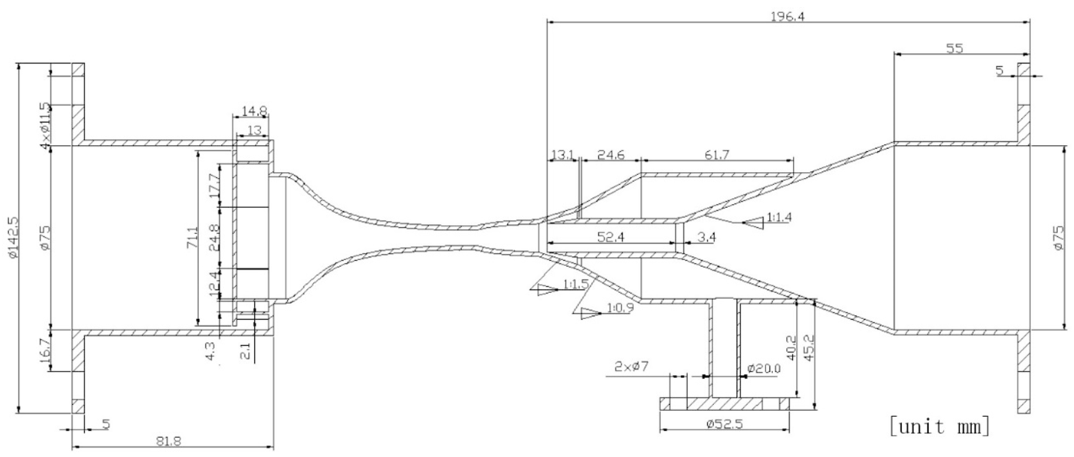
2. Structural Design Method of Supersonic Swirling Separator for Natural Gas Liquefaction

2.1. Design of Nozzle Structure

The designed supersonic nozzle has an axisymmetric structure. The four parts of the nozzle had different design principles.
(1) The inlet stabilization section. In theory, the larger the ratio of the diameter of the stabilization section to the diameter of the throat, the better. The length of the stabilization section was approximately ten times the diameter of the throat.
(2) Subsonic convergence section. Using the Witoszynski curve method, the radius of any cross-section on the convergent section can be calculated using the following equation:
r = r 2 1 [ 1 r 2 r 1 2 ] 1 x 2 l 2 1 + x 2 3 l 2 3 ,
where r is the radius, in mm, of the cross-section at the distance x, in mm, from the inlet of the convergent section; l is the length of the convergent section, in mm; r1 and r2 are the inlet and outlet radii, respectively, of the convergent section, in mm.
(3) Throat. The flow area of the nozzle throat was calculated as follows:
A c = m v * / c *
where Ac is the flow area of the nozzle throat, in m2; m is the gas mass flow, in kg/s; v * is the critical specific volume, in m3/kg; c * is the critical flow velocity, in m/s. v * and c * were obtained using the BWRS equation of state [20].
(4) Supersonic divergent sections. This section was designed based on the Foelsch method [21]. According to the designed Mach number ME, Equation (3) was used to calculate the outlet diameter DE.
A E / A c = M C / M E × 1 + ( k 1 ) M E 2 / 2 / 1 + ( k 1 ) M C 2 / 2 ( k + 1 ) / [ 2 ( k 1 ) ] ,
where AE is the outlet area, in m2; Ac is the throat area, in m2. k is the specific heat ratio of the gas, ME is the Mach number at the outlet, and MC is the Mach number at the throat.

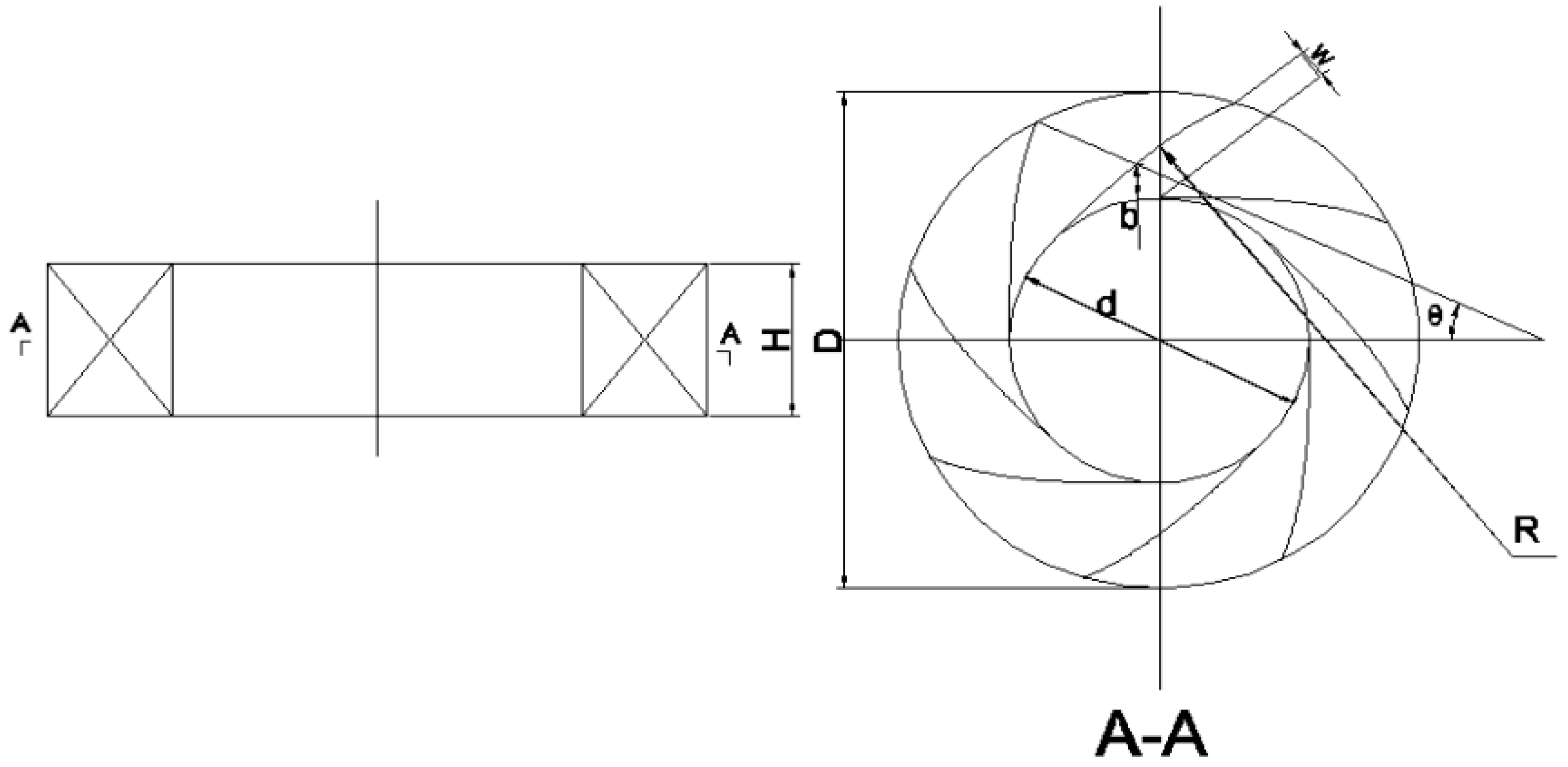
2.2. Design of Swirl Generator

To control the expansion waves and oblique shockwaves easily and to improve the pressure recovery capability of the supersonic separator, a radial swirl generator (Figure 2) was installed in front of the stabilization section of the nozzle inlet to generate swirling gas flow.
The generator consists of several circular arc vanes arranged evenly along the direction of the nozzle inlet cross-section. The ends of the vanes were tangential to the nozzle inlet. The design parameters are as follows: height of the swirl generator H, outer diameter D, inner diameter d, minimum distance between the vanes w, vane thickness b, vane angle θ , vane arc radius R, and number of vanes nsb. The vane arc radius R and vane angle θ are important parameters to be considered when designing vanes. Generally, the inner diameter d of the swirl generator is the same as the inner diameter of the stabilization section of the inlet of the supersonic nozzle. When nsb, w, and b are known, R can be obtained using geometric methods. As shown in Figure 3, O1 and O2 are the centers of the inner circle of the radial swirl generator and arc vanes, respectively. A and D are two points on the inner circle, rnei is the radius of the inner circle, BD is the vane thickness, C is the intersection of the O2C extended line and vane, and BC is the distance between points B and C. O 1 D = O 1 A = r n e i , O 2 C = R , B D = b , and B C = w . β is the angle between the ends of two adjacent vanes: β = 36 0 / n s b and α = 18 0 β .
According to the law of cosines, the following relationship can be obtained from triangle O1BO2 (Figure 3):
O 2 B 2 = O 1 B 2 + O 1 O 2 2 2 cos α O 1 B O 1 O 2 ,
and
R w 2 = r n e i + b 2 + R r n e i 2 2 cos α r n e i + b R r n e i .
From Equation (5), the expression for the vane arc radius can be obtained as:
R = 2 r n e i 1 + cos α r n e i + b + b 2 w 2 2 r n e i w + cos α r n e i + b .
The vane arc angle θ is related to the number of vanes; the larger the number of vanes, the smaller is the angle.
Once the inlet pressure and size of the supersonic nozzle are determined, the swirling intensity of the gas flow inside the supersonic nozzle can be fixed by adjusting the minimum flow area of the swirl generator, Amin.
A s b m i n .

2.3. Design of Diffuser

The function of the diffuser is to reduce the gas flow rate and recover pressure energy. The pressure loss in the diffuser was primarily due to friction and separation losses. Friction loss is the pressure loss caused by the viscosity of the gas itself and its friction with the solid wall. The separation between the boundary layer and the wall of the diffuser causes separation loss. The opening angle of the diffuser is the key factor influencing the local losses. The larger the opening angle, the greater the local losses. The diffuser was designed using the following equation:
d x = ε x + d f ,
ε = d q d f / l q ,
where x is the axial position coordinate measured from the diffuser inlet, df is the outlet diameter of the divergent section of the nozzle, ε is an intermediate variable, and dq and lq are the outlet diameter and length of the diffuser, respectively.

2.4. Design of Discharge Channel

The function of the discharge channel is to collect and drain liquid droplets formed by condensation. The structure is an annular space formed by the outer wall of the diffuser nozzle and inner wall of the discharge channel nozzle. To determine the size of the discharge channel, it is necessary to perform the following steps: design and calculate the cross-sectional areas of different sizes according to the actual processing requirements, perform a comparative analysis of the calculated areas, determine the maxima and minima, perform a comprehensive analysis, and make a decision based on the processing capacity requirements.

3. Mathematical Modeling and Method of Calculation of Supersonic Condensation

3.1. Governing Equations

The assumptions are that in the spontaneous condensation stage, there is no collision between the droplets, so the droplets are not broken and are evenly distributed in the gas phase, and the partial pressure and total pressure of each component conform to Dalton’s law under low pressure. A two-fluid model was established based on the Euler–Euler method, using which the equations for mass, momentum, and energy of the gas phase were established, and the transport equation for gas–liquid mass transfer was also established [22]. The governing equations of the liquid phase were established based on the droplet nucleation and growth theory, where the gas and liquid phases were coupled through the source phase.
The governing equations for the gas-phase flow are as follows:
ρ g t + x j ρ g u j = S m ,
t ρ g u i + x j ρ g u j u i = p x i + x j u u j x i + u i x j 2 3 δ i j u j x j + x j ρ u i u j + S u ,
t ρ g E + x j ρ g u j E + u j p = x j k e f f T x j + u i τ e f f + S h .
where t is the time; x is Cartesian coordinate; ρg is the density of the gas phase; u is the velocity; p is the pressure; T is the temperature; E is the total energy; keff is the effective thermal conductivity; τeff is the effective stress tensor, and subscripts i and j represent the x and y axes, respectively.
The governing equations of liquid-phase flow are as follows [3]:
t ρ Y S + x j ρ u j Y S = S Y S ,
ρ N S t + x j ρ N S u j = J S ,
r d = 3 Y S / 4 π ρ l N S 3 .
where ρ is the density; ρl is the liquid-phase density; Ys is the humidity; Ns is the droplet number; rd is the mean droplet radius.
In Equations (10)–(13), Sm, Su, Sh, and SYS are the source terms of the mass, momentum, energy, and gas–liquid transport equations, which can be expressed as follows:
S m = m S ,
S u = m S u i ,
S h = m S h 1 g h ,
S Y S = m S ,
m S = J S ρ l 4 π r c 3 3 + 4 π r d 3 N S ρ g ρ l d r d d t ,
where ρl is the density of the liquid phase, rd is the average radius of the droplets, rc is the critical radius, hlg is the latent heat of the phase change, and ms is the mass of a single vapor molecule.
Js is the nucleation rate of the droplets, calculated based on classical nucleation theory [23].
J S x = ρ g 2 ρ l 2 σ π m s 3 exp 16 π σ 3 3 k ρ l 2 R g 2 T 3 ln 2 S
σ = 1 1 3 r 4 3 π ρ l m S σ
σ = 0.2358 1 T r 1.256 1 0.625 1 T r
where T is the temperature; Tr is relative temperature; Rg is the gas constant; S is the degree of supersaturation; k is the Boltzmann constant; σ is the droplet surface tension; σ is the liquid plane surface tension.
d r d d t is the growth rate of the droplets, calculated using the Gyarmathy model [24].
d r d d t = λ g ( 1 r c / r ) ( T S T g ) ρ l h 1 g ( r + 8 π 1.5 Pr g k k + 1 2 u R T g p g )
r = 2 σ ρ l R g T g ln S
where Tg is the temperature of the gas phase; Ts is the temperature of the droplet; Pg is the pressure of gas phase; Prg is the vapor-phase Prandtl number; λg is the vapor-phase thermal conductivity.

3.2. Turbulence Model

The flow field simulation in this study has streamline tortuosity and vortices. The Reynolds stress model (RSM) [25] considers streamline tortuosity, vortex, rotation, and rapid changes in tension, which can provide a higher calculation accuracy for complex flows. Therefore, in this study, the RSM model was used as the turbulence model.

3.3. Real Gas Equation of State

Natural gas entering the supersonic nozzle is under conditions of high pressure and low temperature. At this time, the state of natural gas deviates from that of ideal gas. Therefore, the effect of the real gas should be considered. The BWRS equation [26] was selected to calculate the physical parameters of natural gas.

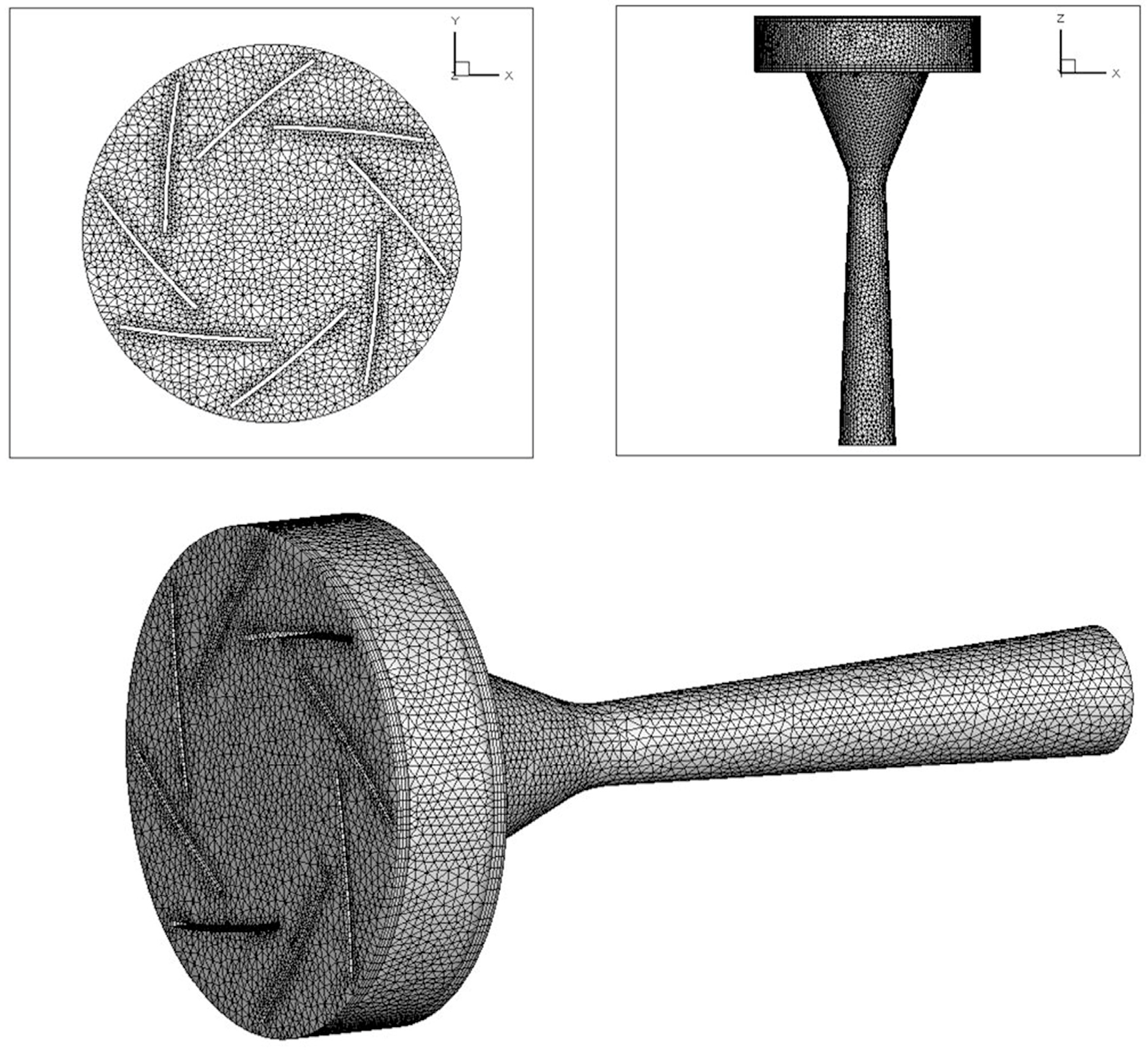
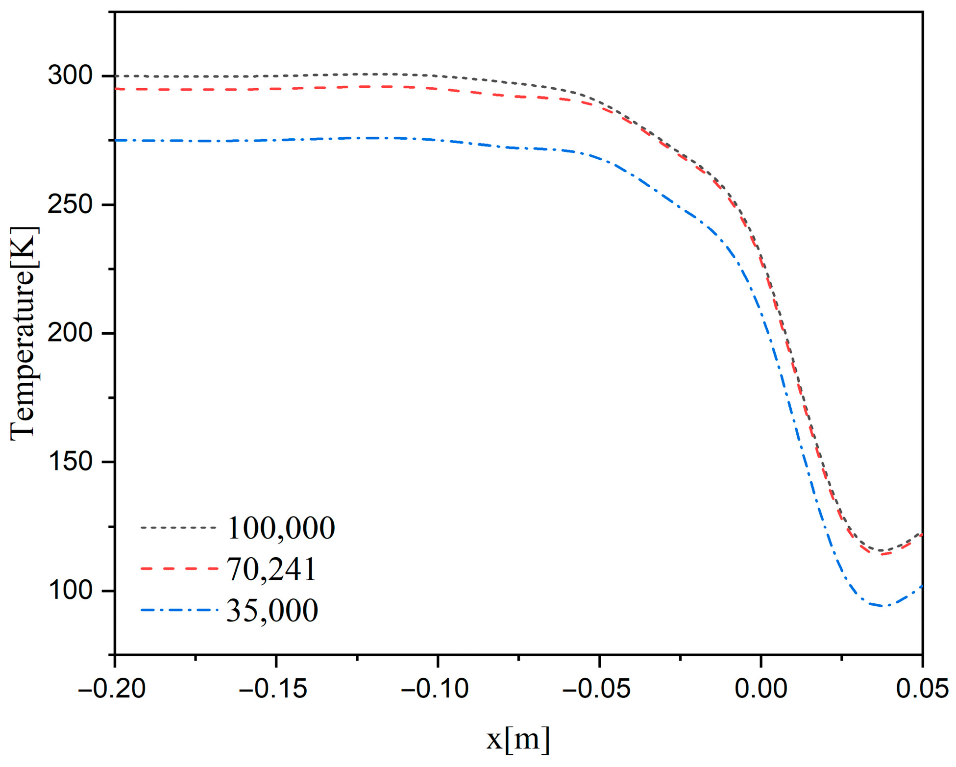
3.4. Numerical Solution

In mathematical modeling, we used the C language to program the user-defined functions (UDFs) for the source terms of the governing equations, applied user-defined scalars (UDSs) to the transport equations, and embedded them in the ANSYS Workbench (ANSYS Co., Pittsburgh, PA, USA).
The gas flow in the supersonic separator was a high-speed compressible flow and was solved based on density. The flow-governing equations, turbulence kinetic energy equations, and turbulence dissipation rate equations were discretized in the second-order upwind scheme. The pressure and velocity fields are coupled using the SIMPLE algorithm. The pressure inlet and outlet were set as the inlet and outlet boundaries, respectively, of the flow parameters. The inlet pressure should be maintained at a constant value, along with the specified total temperature, turbulence parameters, and gas mole fraction. Meanwhile, the walls were subjected to boundary conditions characterized by no-slip and adiabatic properties.
An unstructured mesh (Figure 4) is used for the entire calculation area. The velocity gradients near the de Laval nozzle throat, diffuser inlet, and swirler were large; therefore, the cells were denser in these regions. Owing to the complexity of the flow and geometry within the supersonic separator, three unstructured mesh models with grid densities of 35,000, 70,241, and 100,000 cells were used to ensure mesh independence. The variation in the distribution curve of temperature along the nozzle axis with different cell numbers is shown in Figure 5 (the inlet pressure and the outlet pressure are 4 MPa and 0.9 MPa, respectively). The simulation results indicated that the mesh with a grid density of 70,241 offered the best balance between accuracy and computational efficiency and was therefore selected for all subsequent simulations.

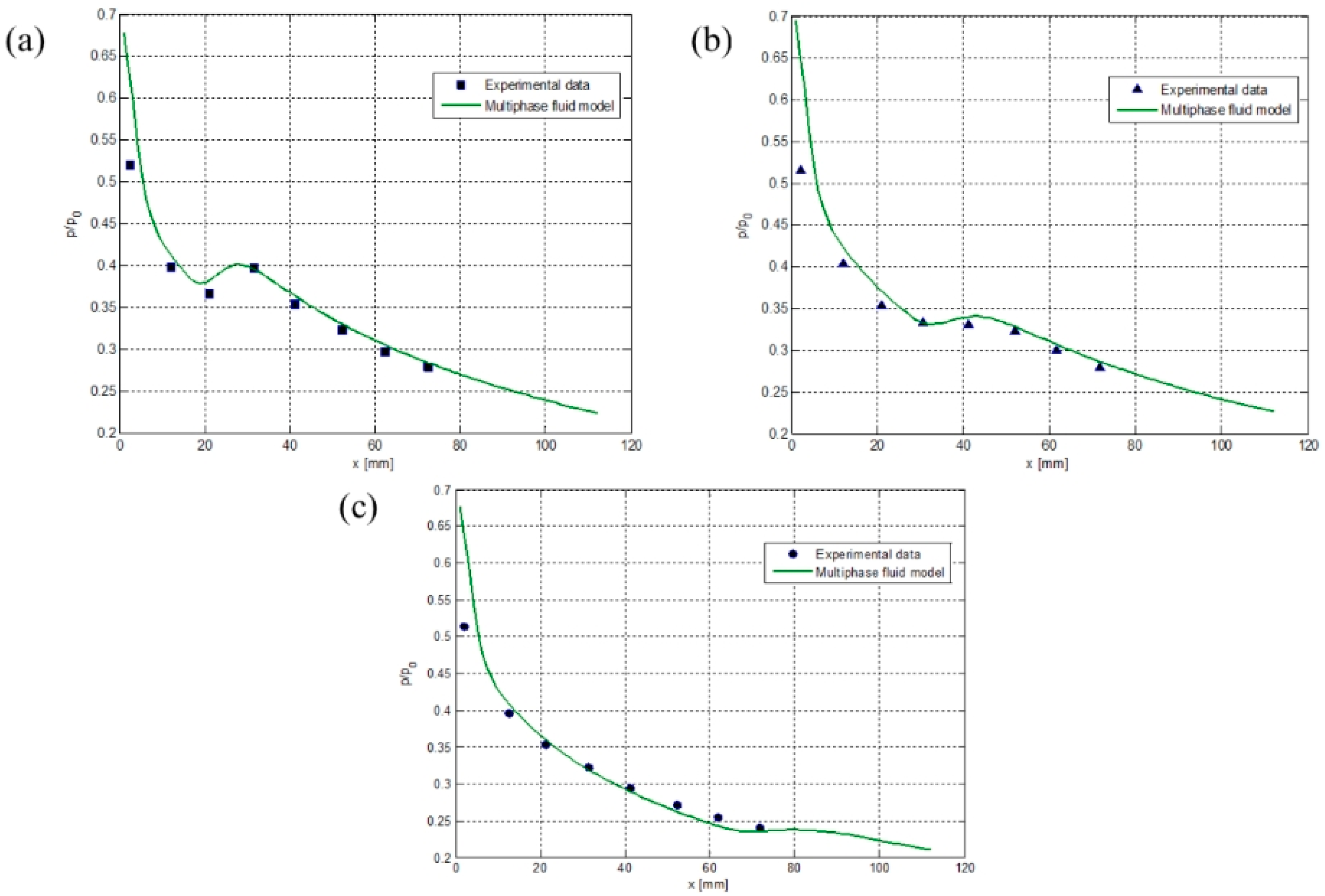
3.5. Model Verification

The nozzle structure and experimental data used by Wyslouzil et al. [27] were used to verify the numerical model. The experimental conditions were as follows: total inlet pressure, 60 kPa; water particle pressure, 1 kPa; inlet temperature, 287.6 K. The inlet pressure was measured along the horizontal direction of the nozzle. The nozzle structure and experimental parameters are presented in Table 1.
L d is the gradually shortened length of the nozzle; L is the length of the gradually expanded section of the nozzle; A o u t / A t h r o a t is the ratio of the outlet area of the gradually expanded section to the throat area of the nozzle; h r e c and b r e c are, respectively, the width and height of the throat of the nozzle; p i n is the nozzle inlet pressure; T i n is the inlet temperature; P i n , w is the inlet steam partial pressure.
A comparison of the experimental and simulation results is shown in Figure 6. As shown in Figure 6, the calculation results of the two-fluid model established in this study are in good agreement with the experimental data under various operating conditions, as well as before and after the spontaneous condensation flow. Because the model avoids the effect of the boundary layers, the simulation results are close to those of the real flow conditions.

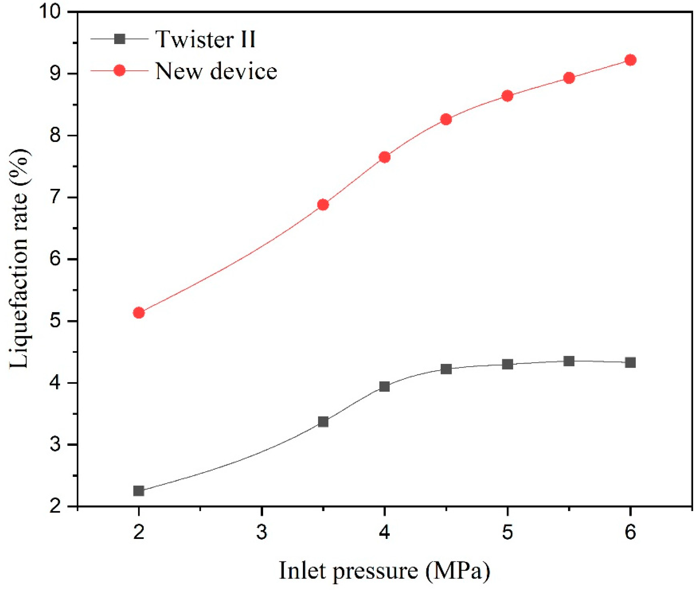
4. Structural Design Case and Analysis
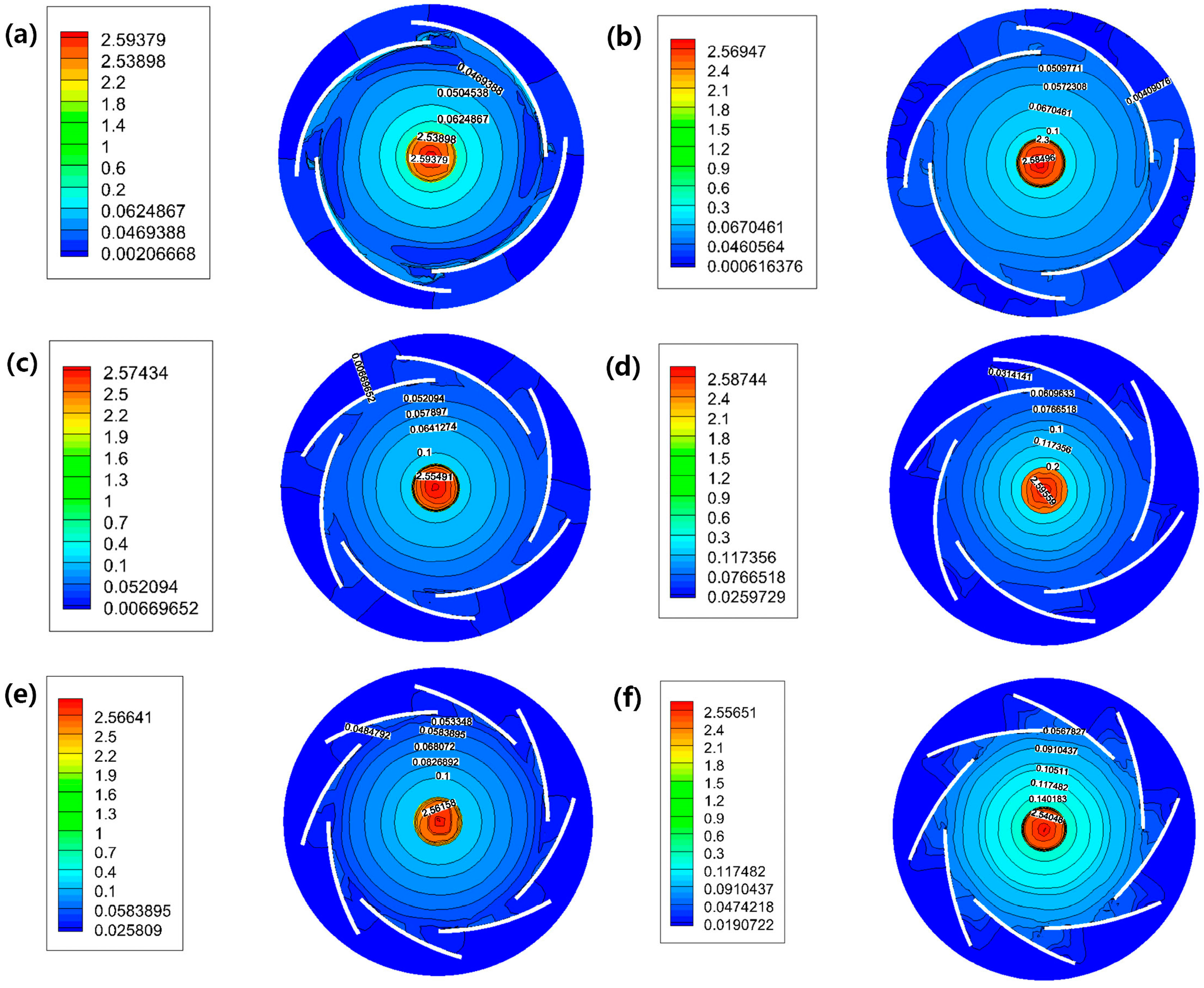
An LNG peak-shaving station was used as the design case. The chemical components of natural gas are shown in Table 2. The natural gas processing capacity of the station was 4706 Sm3/h, the pressure at the gas source inlet was 4 MPa, the initial temperature was 300 K, and the pressure at the outlet of the device that formed the LNG after processing was 0.9 MPa. An integrated cascade liquefaction process was used to produce LNG. The tank storage conditions for product storage were as follows: temperature, 112.5 K and pressure, 0.11 MPa. A supersonic swirling separator was designed to replace the throttling refrigeration valve installed in the process system (with an inlet pressure of 2 MPa). The structural design was performed sequentially.

4.1. Swirler Design

To design the swirler, we simulated and analyzed various combinations of the designs (Table 3). Through the analysis of the nozzle pressure distribution, Mach number distribution, and centripetal acceleration distribution, we developed a swirler design suitable for the desired operating conditions.
Figure 7 shows the pressure distribution for various combinations of vanes and channel widths. It can be seen from Figure 7 that, from the perspective of the total pressure distribution, the pressure loss is the highest for the swirler design containing six vanes and an 8 mm wide channel and a nozzle, and the pressure loss is the lowest for the swirler design containing six vanes and a 6 mm wide channel and a nozzle. However, the difference in the pressure loss between the two designs was only 0.01 MPa. Therefore, it may be concluded that the combination of the number of vanes and channel widths has little effect on the pressure loss.
Figure 8 shows the Mach number distribution for various combinations of number of vanes and channel widths. As shown in Figure 8, the combination of the number of vanes and channel widths has little effect on the Mach number distribution because it results in only a small pressure loss and a minor impact on the pressure at the inlet of the supersonic nozzle. For these nozzles, the Mach number of the nozzle outlet depended only on the geometric dimensions of the supersonic nozzle profile and the ratio of the back pressure at the outlet to the pressure at the inlet. Therefore, the combination of the number of vanes and the channel widths resulted in little variation in the Mach number of the entire nozzle.
The main purpose of identifying a suitable swirler design is to achieve gas–liquid separation by generating a centrifugal force. It can be observed from Figure 9 that the centripetal force distribution is mainly located in the annular space near the nozzle wall in Designs 1 and 2, and that the centripetal acceleration distribution is mainly located near the axis of the nozzle in Design 3. Therefore, it is expected that Design 3 may cause the formed droplets to mix with the gas flow; thus, it may not effectively achieve gas–liquid separation. In terms of centripetal acceleration distribution, it was observed that the combination of six vanes and an 8-mm wide channel of Design 2 produced a larger centrifugal force in the annular space of the nozzle as compared to Design 1; therefore, Design 2 was identified to be the best design. It may be concluded that, while designing a swirler, to obtain the best swirling separation performance, it is important that the size and structure of the swirler ensure a low pressure loss and that a large centripetal acceleration is generated in the annular space near the nozzle wall.

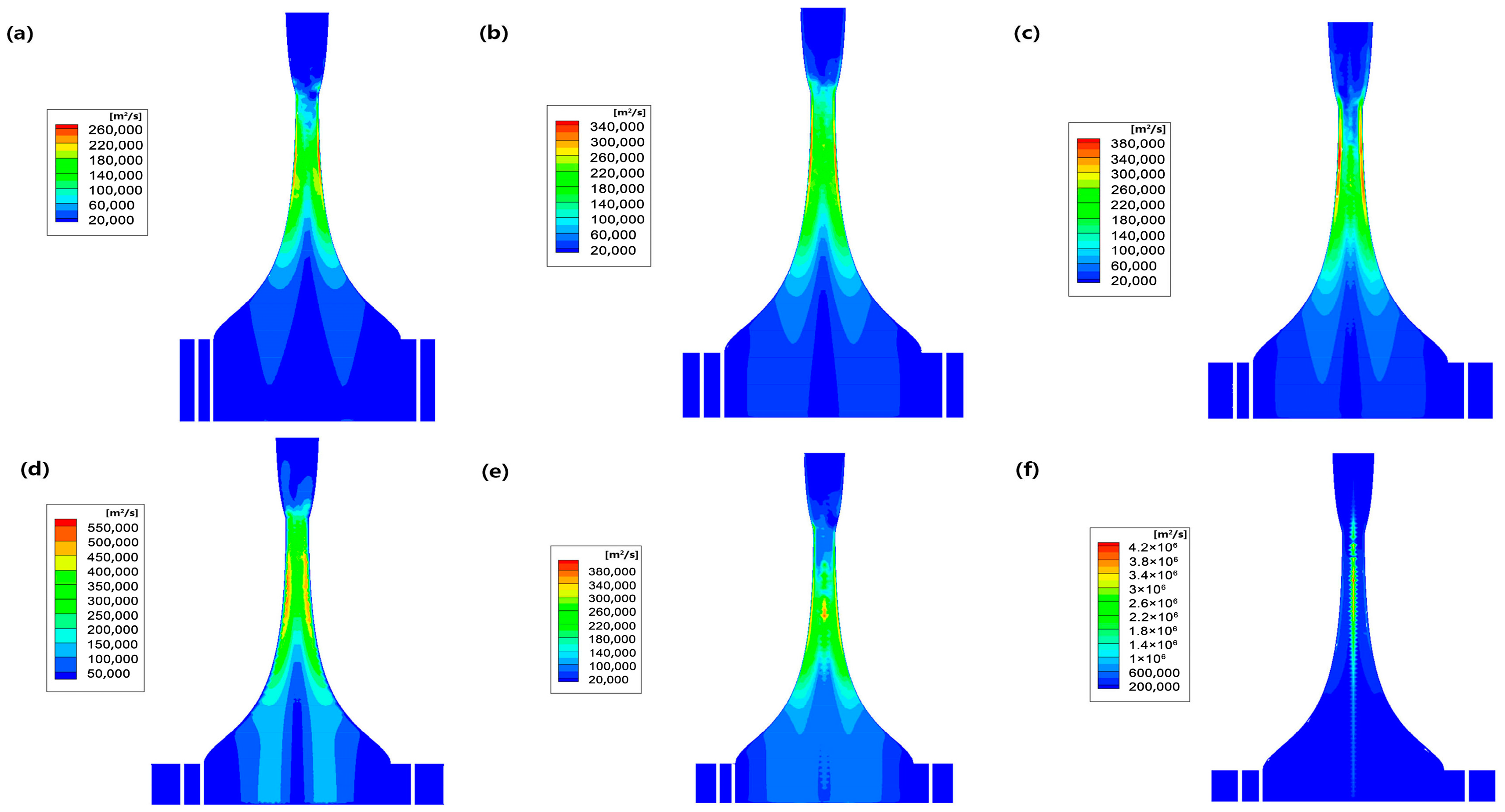
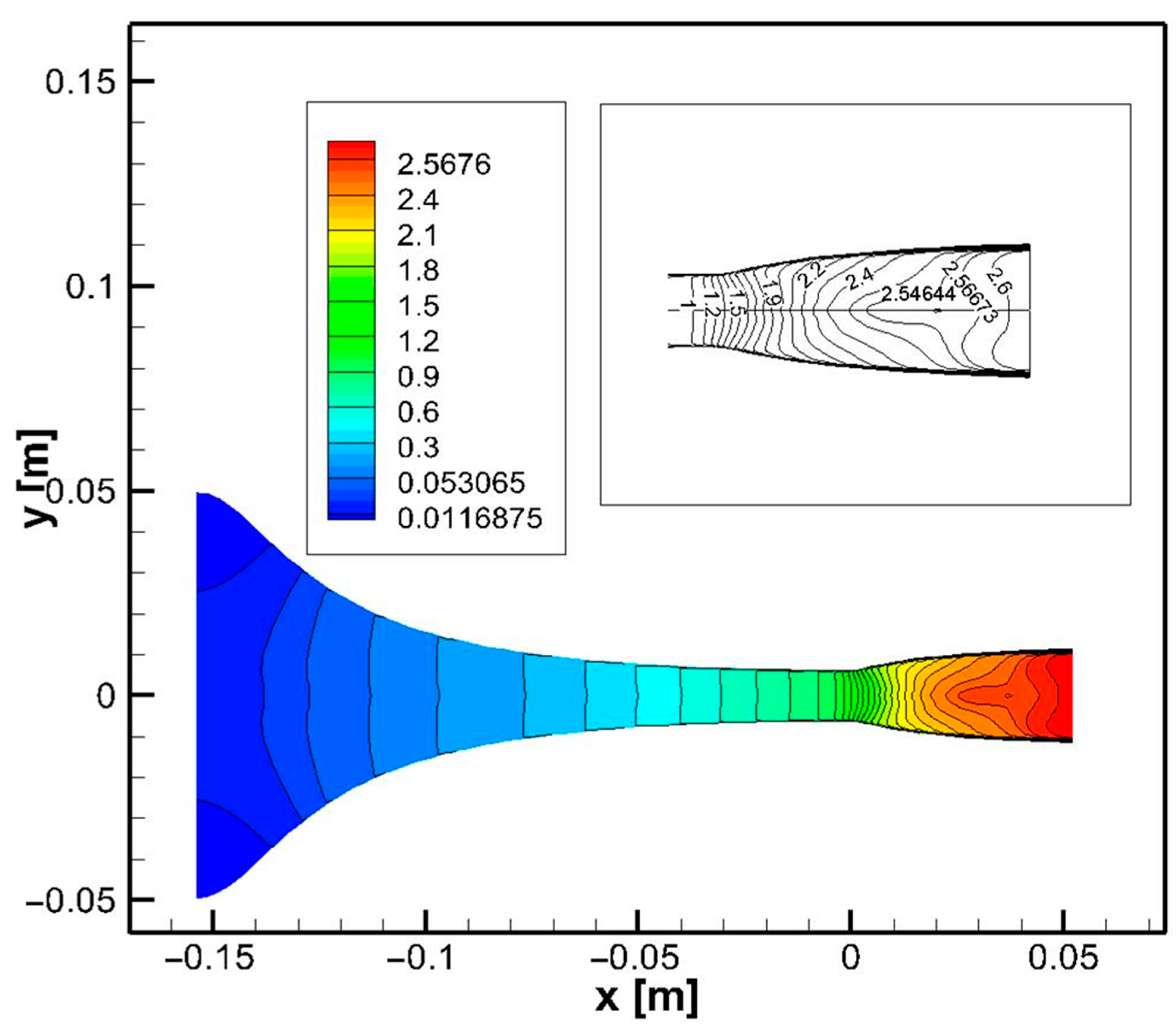
4.2. Nozzle Structure

The structural dimensions of the supersonic nozzle section of the separator were calculated using Equation (1) and are listed in Table 4. It may be seen from Figure 10 and Figure 11 that the designed supersonic nozzle section is able to achieve supersonic speed at the throat and achieve a temperature drop of more than 170 K, and no obvious shockwaves are present. Figure 12 and Figure 13 show that the internal pressure changed smoothly. The absence of obvious shockwave generation can be used as a basis for evaluating the nozzle structure design.

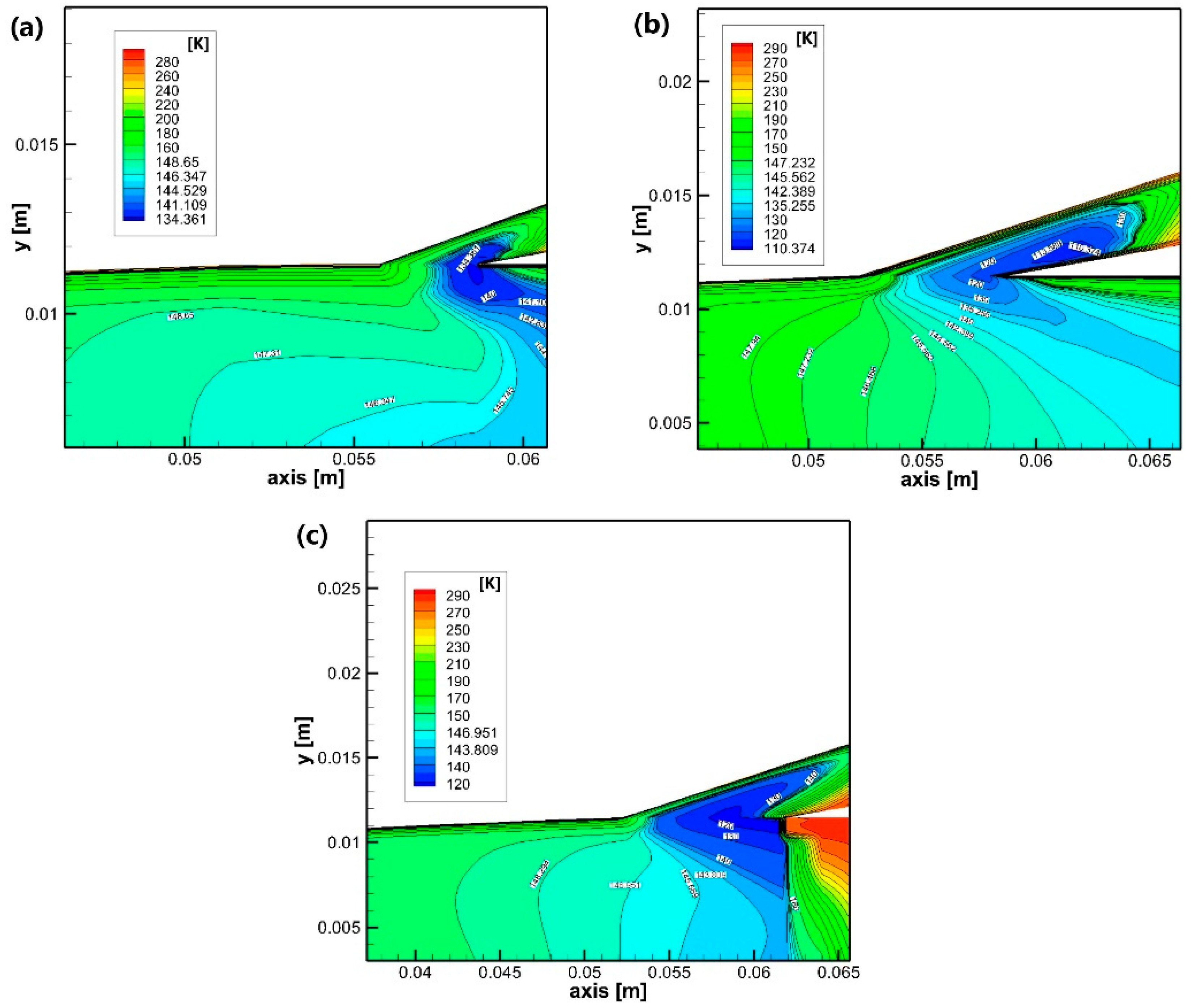
4.3. Design of Diffuser and Straight Tube Section

To ensure that normal shockwaves do not enter the separation section, it is necessary to design a straight tube section of a certain length in front of the diffuser. In addition, when the diameter of the throat is fixed, the opening angle of the diffuser is the key factor affecting the local pressure loss, whereas the length of the straight tube directly determines the position of the normal shockwaves. Figure 14 shows the normal shockwave generation locations under varying lengths of the straight tube section (multiples of the nozzle outlet diameter) and a fixed diffuser opening angle. Figure 15 shows the normal shockwave generation locations for different expansion angles and fixed lengths of the straight tube section.
It can be observed from Figure 14a that normal shockwaves always occur in the straight tube section. The shorter the straight tube section, the closer the normal shockwaves are to the separation section. The longer the straight tube section, the closer the normal shockwaves occur to the diffuser; however, they do not enter the diffuser. The distributions of the normal shockwaves in Figure 14b,c present the same pattern as in Figure 14a. At different opening angles, when the straight tube section is 10D, the normal shockwaves generated are farthest from the separation section. As shown in Figure 15a, the larger the opening angle of the divergent section, the closer the normal shockwave generation location in the straight tube section is to that of the separation section. The distributions of normal shockwaves in Figure 15b,c show the same pattern as in Figure 15a, where the opening angles for the shockwaves closest to and farthest away from the separation section are 28° and 20°, respectively. Based on the above analysis, it was concluded that the design consisting of a straight tube section with a length of 10D and a divergent section with an opening angle of 20° is the best design. It can be seen that the key to the designing the diffuser is to recover as much pressure energy as possible while ensuring that the shockwaves do not enter the separation section.

4.4. Design of Discharge Gap

The main function of the discharge gap is to collect the formed droplets through the discharge channel under the action of centrifugal force and finally achieve gas–liquid separation. Because there is no theoretical model to determine the discharge gap size, it must be determined by a simulation analysis based on the operating conditions. In this paper, a total of three gap sizes were designed. The results of the simulation analysis are shown in Figure 16.
As shown in Figure 16c, the shockwaves move forward to the gap entrance, and the temperature in the gap increases significantly at a gap size of 3 mm. However, in Figure 16a,b, it can be seen that there is no forward movement of the shockwaves and that the temperature drops after the flow enters the gap. The temperature drop in the 1 mm gap was not as large as that in the 2 mm gap. The main reason for this observation is that the smaller the gap, the greater the friction, which increases the temperature. The main reason for the temperature drop after the entry of the flow into the gap was that the temperature continued to decrease owing to the secondary expansion effect. Therefore, the design with a 2 mm gap size is the best suited design. It may be seen that the locations of shockwave generation and friction are the important parameters in the process of gap design. Because a larger gap size is not always better in terms of ensuring the liquid yield, it is necessary to comprehensively consider the influence of the gap size on the pressure and temperature of the flow field simulation.
The optimal dimensions suitable for the specified processing capacity from the above design and analysis of the key dimensions of the supersonic separator are shown in Figure 17.
Taking liquefaction efficiency as the target parameter, the performance of the supersonic cyclone separator designed in this study is compared with “Twister II” [28]. The natural gas flow rate was 4706 Sm3/h. The initial temperature was 300 K. pressure at the gas source inlet was varied from 2 MPa to 6 MPa. The gas composition is listed in Table 2. The liquefaction rates of the device at different pressures are shown in Figure 18. The liquefaction rate increased with the inlet pressure. Compared with “Twister II”, the new supersonic cyclone separator exhibited better liquefaction performance.

5. Summary

(1) Based on the Euler–Euler method to establish a two-fluid model, a supersonic condensation mathematical model was established, and a set of governing equations to describe the complex flow processes was constructed. Compared with classical experimental data, the established model was found to accurately simulate the location and intensity of spontaneous gas condensation, and it was also found to have a strong ability to capture shockwaves. The results were in good agreement with the experimental data.
(2) Through simulation analysis, the optimal structure of the supersonic swirling separator suitable for the natural gas processing capacity of an LNG peak-shaving station was obtained. The structure consists of a swirler with six vanes and an 8-mm wide channel, a 10D-long straight tube section, a divergent section with an opening angle of 20°, and a 2 mm wide gap.
(3) The key design criteria for each part were determined as follows: the nozzle should not have noticeable shockwaves. The swirler should not only ensure a small pressure loss but also produce large centripetal acceleration. The normal location of shockwave generation should be fully considered while designing the opening angle of the diffuser and the length of the straight tube section. A larger gap size is not always preferable because it is significantly affected by the shockwave generation location and friction.
(4) Under the same analysis conditions, the liquefaction performance of “Twister II” and the supersonic cyclone separator proposed in this study were compared. The results showed that the liquefaction efficiency increased with an increase in the inlet pressure. Moreover, the supersonic swirling device proposed in this study achieves a higher liquefaction efficiency.

Author Contributions

Methodology, Q.H., H.H. and X.L.; Software, Q.H., H.H., X.L. and Y.T.; Formal analysis, X.L.; Investigation, Q.H., X.L., Y.T. and J.M.; Resources, Q.H.; Data curation, Q.H., H.H., Y.T. and J.M.; Writing – original draft, H.H.; Writing – review & editing, Y.T.; Supervision, J.M.; Project administration, X.L.; Funding acquisition, H.H. All authors have read and agreed to the published version of the manuscript.

Funding

This research was funded by the National Natural Science Foundation of China (51904051, 52302402), the Natural Science Foundation of Chongqing, China (CSTB2024NSCQ-MSX1103, cstc2021jcyj-msxmX0918, cstc2021jcyj-msxmX0978), the Science and Technology Research Program of the Chongqing Municipal Education Commission (No. KJQN202101545).

Institutional Review Board Statement

Not applicable.

Informed Consent Statement

Not applicable.

Data Availability Statement

The datasets generated during and/or analyzed during the current study are available from the corresponding author upon reasonable request.

Conflicts of Interest

The authors declare no conflict of interest.

References

  1. Gaidai, O.; Cao, Y.; Ashraf, A.; Sheng, J.; Zhu, Y.; Liu, Z. FPSO/LNG hawser system lifetime assessment by Gaidai multivariate risk assessment method. Energy Inform. 2024, 7, 51. [Google Scholar] [CrossRef]
  2. Long, X.; Huang, Q.; Tian, Y.; Mu, L. Effects of the operating parameters of supersonic separators on the supersonic liquefaction characteristics of natural gas. Energies 2022, 15, 2531. [Google Scholar] [CrossRef]
  3. Bian, J.; Cao, X.; Yang, W.; Du, H.; Yin, P. Effects of external particles on the liquefaction property of natural gas in a Laval nozzle. Powder Technol. 2018, 339, 894–902. [Google Scholar] [CrossRef]
  4. Bian, J.; Cao, X.; Yang, W.; Song, X.; Xiang, C.; Gao, S. Condensation characteristics of natural gas in the supersonic liquefaction process. Energy 2019, 168, 99–110. [Google Scholar] [CrossRef]
  5. Cao, X.; Bian, J. Supersonic separation technology for natural gas processing: A review. Chem. Eng. Process. Process Intensif. 2019, 136, 138–151. [Google Scholar] [CrossRef]
  6. Ding, H.; Zhang, Y.; Sun, C.; Yang, Y.; Wen, C. Numerical simulation of supersonic condensation flows using Eulerian-Lagrangian and Eulerian wall film models. Energy 2022, 258, 124833. [Google Scholar] [CrossRef]
  7. Bian, J.; Jiang, W.; Teng, L.; Liu, Y.; Wang, S.; Deng, Z. Structure improvements and numerical simulation of supersonic separators. Chem. Eng. Process. Process Intensif. 2016, 110, 214–219. [Google Scholar] [CrossRef]
  8. Cao, X.; Yang, W. Numerical simulation of binary-gas condensation characteristics in supersonic nozzles. J. Nat. Gas Sci. Eng. 2015, 25, 197–206. [Google Scholar] [CrossRef]
  9. Wang, Y. Analysis for spiral vortex and effect of profile of nozzle and swirler on performance of supersonic separator. Chem. Eng. Process.-Process Intensif. 2020, 147, 107676. [Google Scholar] [CrossRef]
  10. Dengyu, J.; Eri, Q.; Wang, C.; Liu, H.; Yuan, Y. A fast and efficiency numerical simulation method for supersonic gas processing. In Proceedings of the International Oil and Gas Conference and Exhibition in China, Beijing, China, 8–10 June 2010; OnePetro: Richardson, TX, USA, 2010. [Google Scholar]
  11. Shoghl, S.N.; Naderifar, A.; Farhadi, F.; Pazuki, G. A novel strategy for comprehensive optimization of structural and operational parameters in a supersonic separator using computational fluid dynamics modeling. Sci. Rep. 2021, 11, 21850. [Google Scholar] [CrossRef] [PubMed]
  12. Guo, X.; Yang, M.; Li, F. Investigation on Cryogenic Cavitation Characteristics of an Inducer Considering Thermodynamic Effects. Energies 2024, 17, 19961073. [Google Scholar] [CrossRef]
  13. Tan, Y.; Ni, Y.; Wu, J.; Li, L.; Tan, D. Machinability evolution of gas–liquid-solid three-phase rotary abrasive flow finishing. Int. J. Adv. Manuf. Technol. 2024, 131, 2145–2164. [Google Scholar] [CrossRef]
  14. Malyshkina, M. The procedure for investigation of the efficiency of purification of natural gases in a supersonic separator. High Temp. 2010, 48, 244–250. [Google Scholar] [CrossRef]
  15. Wen, C.; Cao, X.; Yang, Y.; Zhang, J. Supersonic swirling characteristics of natural gas in convergent-divergent nozzles. Pet. Sci. 2011, 8, 114–119. [Google Scholar] [CrossRef]
  16. Vlasenko, V.; Slesarenko, V.; Yudakov, A.; Gulkov, A.; Bashirov, K. Three-flow vortex tube: The effect of swirling method and separation insert gap on operational efficiency. Int. J. Therm. Sci. 2022, 173, 107399. [Google Scholar] [CrossRef]
  17. Wu, H.; Jurčević, M.; Ström, H.; Khurram, M.S.; Jin, H. Numerical simulation of condensation of supercritical water gasification products in a supersonic nozzle. Int. J. Fluid Eng. 2024, 1, 043903. [Google Scholar] [CrossRef]
  18. Chen, J.; Wang, T.; Li, A.; Huang, Z.; Jiang, W.; Xi, G. Effect of wall thermal condition on the nonequilibrium condensation of CO2 in supersonic flows. Int. J. Therm. Sci. 2024, 195, 108650. [Google Scholar] [CrossRef]
  19. Wen, C.; Cao, X.; Yang, Y.; Li, W. Numerical simulation of natural gas flows in diffusers for supersonic separators. Energy 2012, 37, 195–200. [Google Scholar] [CrossRef]
  20. Ren, H.Y.; Li, C.J.; Xie, G. Evaluation of state equations of natural gas in pipeline transportation. Adv. Mater. Res. 2012, 463, 936–939. [Google Scholar] [CrossRef]
  21. Foelsch, K. The analytical design of an axially symmetric Laval nozzle for a parallel and uniform jet. J. Aeronaut. Sci. 1949, 16, 161–166. [Google Scholar] [CrossRef]
  22. Bian, J.; Cao, X.; Yang, W.; Guo, D.; Xiang, C. Prediction of supersonic condensation process of methane gas considering real gas effects. Appl. Therm. Eng. 2020, 164, 114508. [Google Scholar] [CrossRef]
  23. Bakhtar, F.; Young, J.; White, A.; Simpson, D. Classical nucleation theory and its application to condensing steam flow calculations. Proc. Inst. Mech. Eng. Part C J. Mech. Eng. Sci. 2005, 219, 1315–1333. [Google Scholar] [CrossRef]
  24. Gyarmathy, G. Grundlagen Einer Theorie der Nassdampfturbine. Ph.D. thesis, ETH Zürich, Zürich, Switzerland, 1962. [Google Scholar]
  25. Li, C.; Huang, Q. Rheology-based computational fluid dynamics modeling for de-oiling hydrocyclone efficiency. Chem. Eng. Technol. 2016, 39, 899–908. [Google Scholar] [CrossRef]
  26. Li, Y.; Feng, Y.; Wang, W.; Zhong, J.; Zhang, D. Application of BWRS equation of state for calculation of fluid density and viscosity. Pet. Sci. Technol. 2022, 40, 1423–1436. [Google Scholar] [CrossRef]
  27. Wyslouzil, B.E.; Heath, C.H.; Cheung, J.L.; Wilemski, G. Binary condensation in a supersonic nozzle. J. Chem. Phys. 2000, 113, 7317–7329. [Google Scholar] [CrossRef]
  28. Schinkelshoek, P.; Epsom, H. Supersonic gas conditioning-low pressure drop twister for NGL recovery. In Proceedings of the Offshore Technology Conference, Houston, TX, USA, 1–4 May 2006. [Google Scholar]
Figure 1. Structure of supersonic swirling separator.
Applsci 15 00151 g001
Figure 2. Schematic of the radial swirl generator.
Applsci 15 00151 g002
Figure 3. Schematic of blade dimension calculation.
Applsci 15 00151 g003
Figure 4. Grid generation of supersonic swirling separator.
Applsci 15 00151 g004
Figure 5. Distribution curve of temperature along the nozzle axis at different cells.
Applsci 15 00151 g005
Figure 6. Comparison of static pressure ratio of nozzle axis with experimental data. (a) inlet steam partial pressure, 1.0 kPa; (b) inlet steam partial pressure, 0.5 kPa; and (c) inlet steam partial pressure 0.26 kPa.
Applsci 15 00151 g006
Figure 7. Pressure distribution at different nozzle sections: (a) four vanes, 6 mm wide channel; (b) four vanes, 8 mm wide channel; (c) six vanes, 6 mm wide channel; (d) six vanes, 8 mm wide channel; (e) eight vanes, 6 mm wide channel; and (f) eight vanes, 8 mm wide channel.
Applsci 15 00151 g007
Figure 8. Mach number distributions at different nozzle sections: (a) four vanes, 6 mm wide channel; (b) four vanes, 8 mm wide channel; (c) six vanes, 6 mm wide channel; (d) six vanes, 8 mm wide channel; (e) eight vanes, 6 mm wide channel; and (f) eight vanes, 8 mm wide channel.
Applsci 15 00151 g008
Figure 9. Centripetal acceleration distribution at different nozzle sections: (a) four vanes, 6 mm wide channel; (b) four vanes, 8 mm wide channel; (c) six vanes, 6 mm wide channel; (d) six vanes, 8 mm wide channel; (e) eight vanes, 6 mm wide channel; and (f) eight vanes, 8 mm wide channel.
Applsci 15 00151 g009
Figure 10. Distribution cloud of Mach numbers in the nozzle.
Applsci 15 00151 g010
Figure 11. Distribution curve of temperature along the nozzle axis.
Applsci 15 00151 g011
Figure 12. Distribution curve of pressure along the nozzle axis.
Applsci 15 00151 g012
Figure 13. The distribution curve of pressure along the nozzle axis.
Applsci 15 00151 g013
Figure 14. Pressure distribution of straight section at lengths 6D, 8D, and 10D and expansion angles (a) 20°, (b) 24°, and (c) 28°.
Applsci 15 00151 g014
Figure 15. Pressure distributions at different lengths of the straight pipe at 20°, 24°, and 28°: (a) 6D; (b) 8D; and (c) 10D.
Applsci 15 00151 g015
Figure 16. Temperature distributions in the discharge gap under different clearance sizes: (a) 1 mm; (b) 2 mm; and (c) 3 mm.
Applsci 15 00151 g016
Figure 17. Dimensions of the supersonic cyclone separator for natural gas liquefaction.
Applsci 15 00151 g017
Figure 18. Influence of inlet pressure on liquefaction rate.
Applsci 15 00151 g018
Table 1. Nozzle structure and experimental parameters.
Nozzle StructureExperimental Parameters
L d
(mm)
L
(mm)
A o u t / A t h r o a t h r e c
(mm)
b r e c
(mm)
p i n
(kPa)
T i n
(K)
P i n , w
(kPa)
38951.58512.7602871.000.500.26
Table 2. Components of natural gas.
Chemical ComponentC1C2C3iC4nC4iC5nC5N2
Mole fraction (%)91.88.10.100000
Table 3. Design scheme of cyclone separator.
DesignNumber of VanesChannel Width
(mm)
Swirler Height
(mm)
Vane Arc Radius
(mm)
Swirler Outer Diameter
(mm)
Vane Arc Opening Angle (Degrees)
Design 14652.0058.39135.0090.00
839.0060.85141.00
Design 26634.0071.04145.0060.00
826.0079.13155.00
Design 38626.00103.13143.0030.00
820.00140.60155.0025.00
Table 4. Structural dimensions of supersonic nozzle section.
Convergent Section
(mm)
Divergent Section
(mm)
Throat Diameter
(mm)
Inlet Diameter
(mm)
Outlet Diameter
(mm)
153.9352.2112.4299.315.95
Disclaimer/Publisher’s Note: The statements, opinions and data contained in all publications are solely those of the individual author(s) and contributor(s) and not of MDPI and/or the editor(s). MDPI and/or the editor(s) disclaim responsibility for any injury to people or property resulting from any ideas, methods, instructions or products referred to in the content.

