
Cylindrical Steel Tanks Subjected to Long-Duration and High-Pressure Triangular Blast Load: Current Practice and a Numerical Case Study

 , ,
, ,
Abstract
1. Introduction
2. Simulation of Blast Events
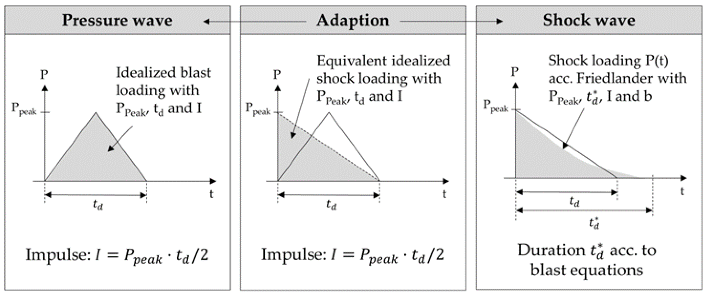
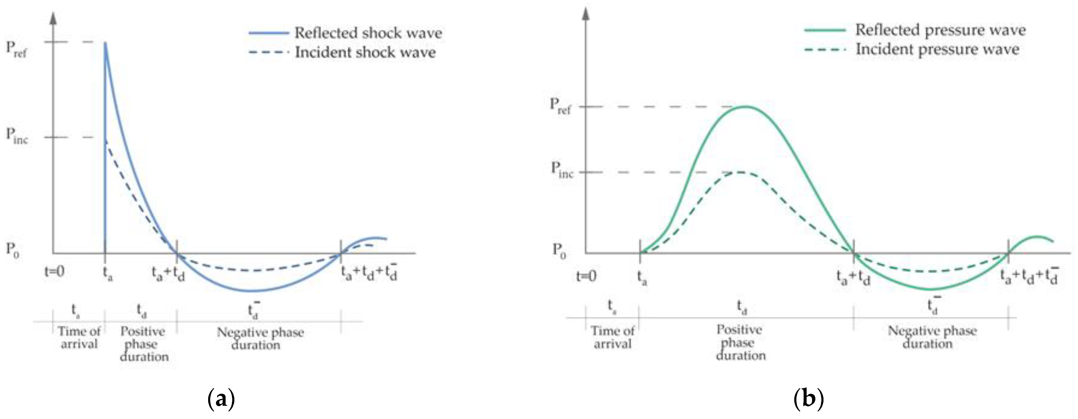
2.1. Characteristics of Blast Load and Pressure Wave Propagation
2.2. Determination of Shock Wave Parameter
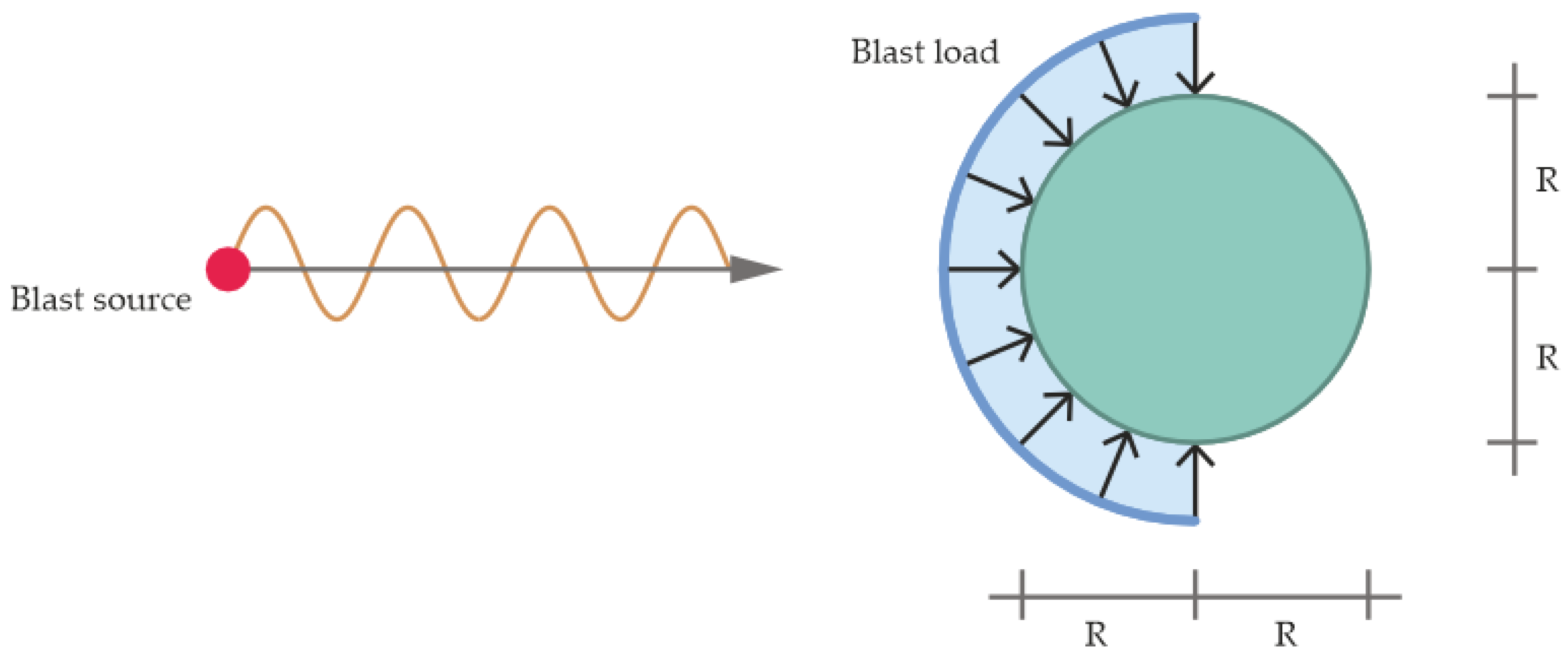
- The velocity of propagation of the shock wave is considered; elements located farther from the explosive charge are loaded later than elements located at a shorter distance; the velocity and the arrival time of the shock wave are the relevant parameters.
- The peak pressure decreasing with the distance from the detonation source is considered; elements located farther from the explosive charge have a lower peak pressure than elements at a shorter distance; the determination of the maximal incident and reflected blast overpressures and their corresponding impulses is relevant.
- The loading duration of the applied shock wave is considered; elements located farther away from the explosive charge are loaded for a longer time than elements located at a shorter distance; the determination of the positive (and negative) pressure phase duration is relevant.
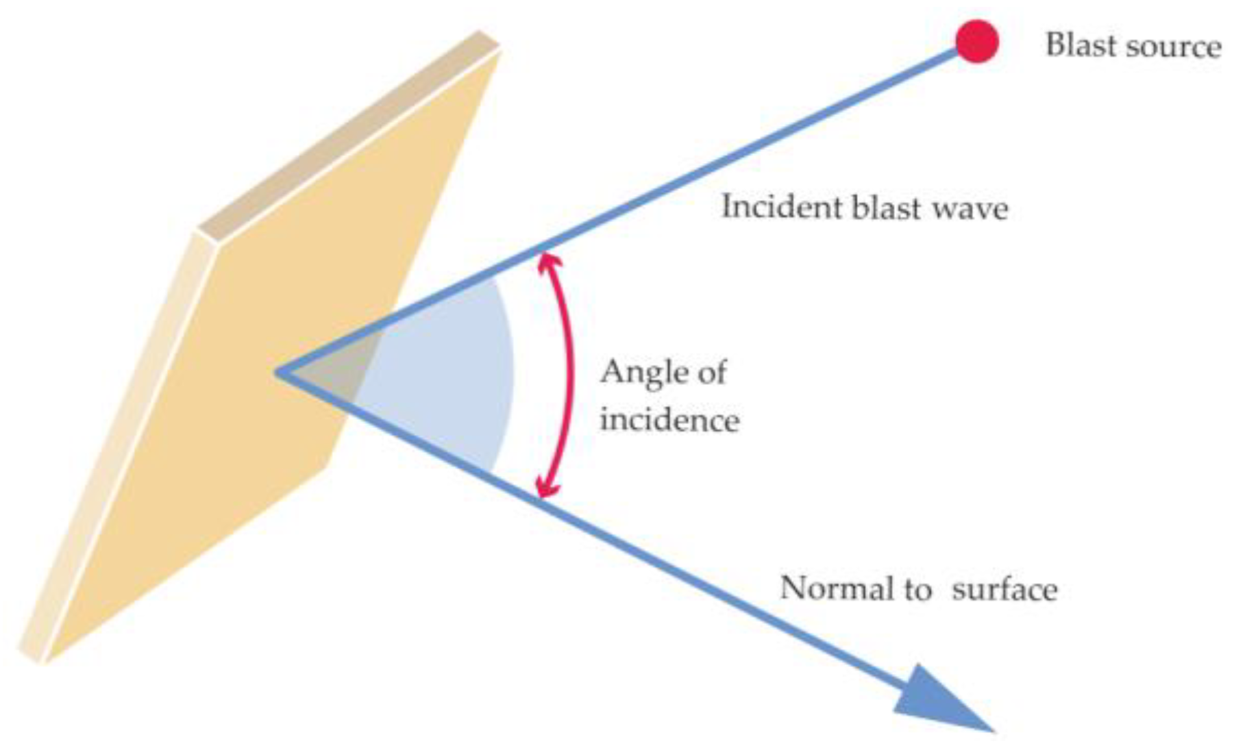
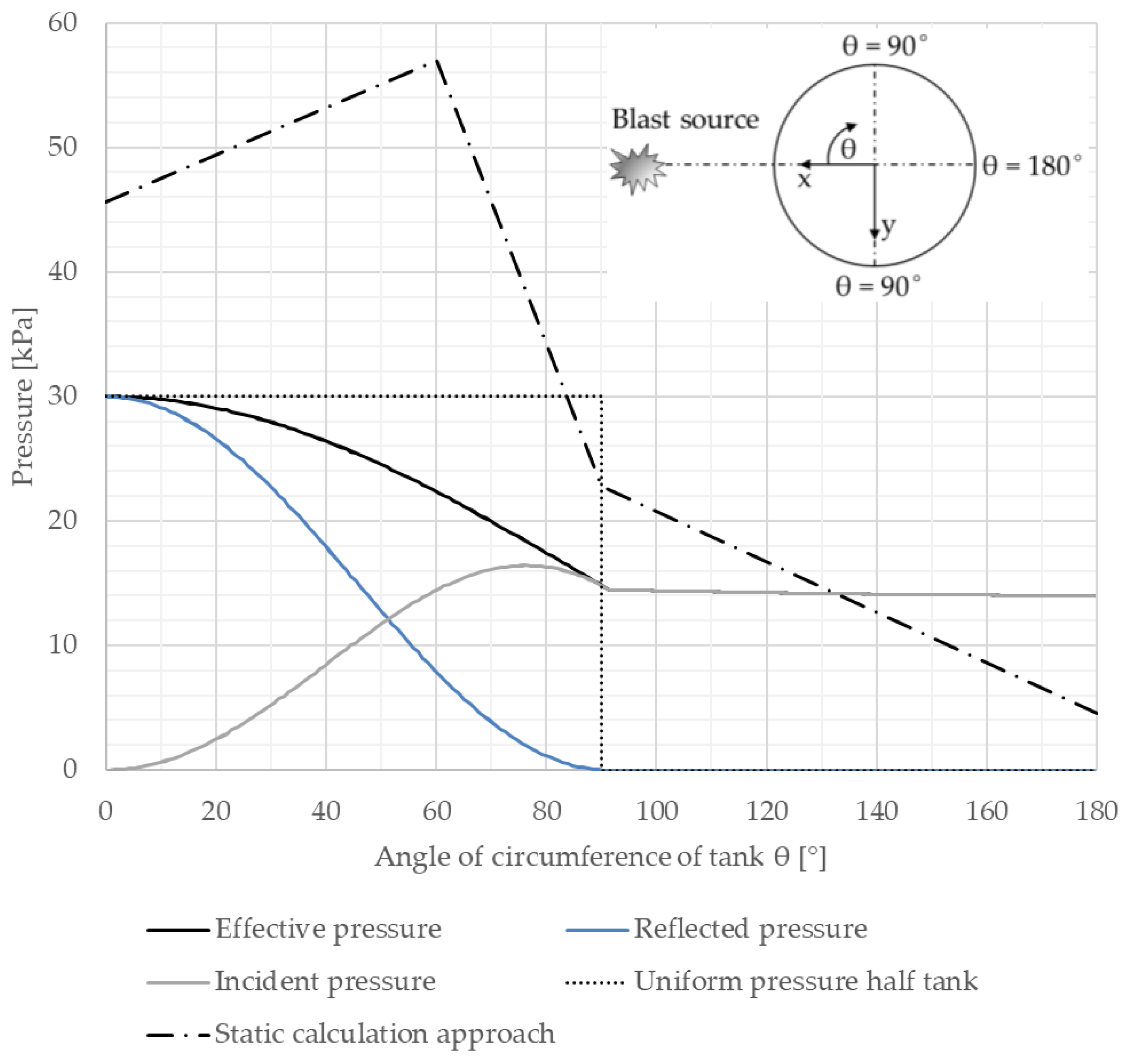
- Structural parts that are oriented perpendicular to the blast wave direction receive the maximal reflected pressure: θ = 0°: Peff = Pref.
- Structural parts that face away from the charge receive only the incident pressure: 90° ≤ θ ≤ 180°: Peff = Pinc.
2.3. Determination of Pressure Wave Parameter
2.4. State of the Art on Blast Load Analyses of Tank Structures
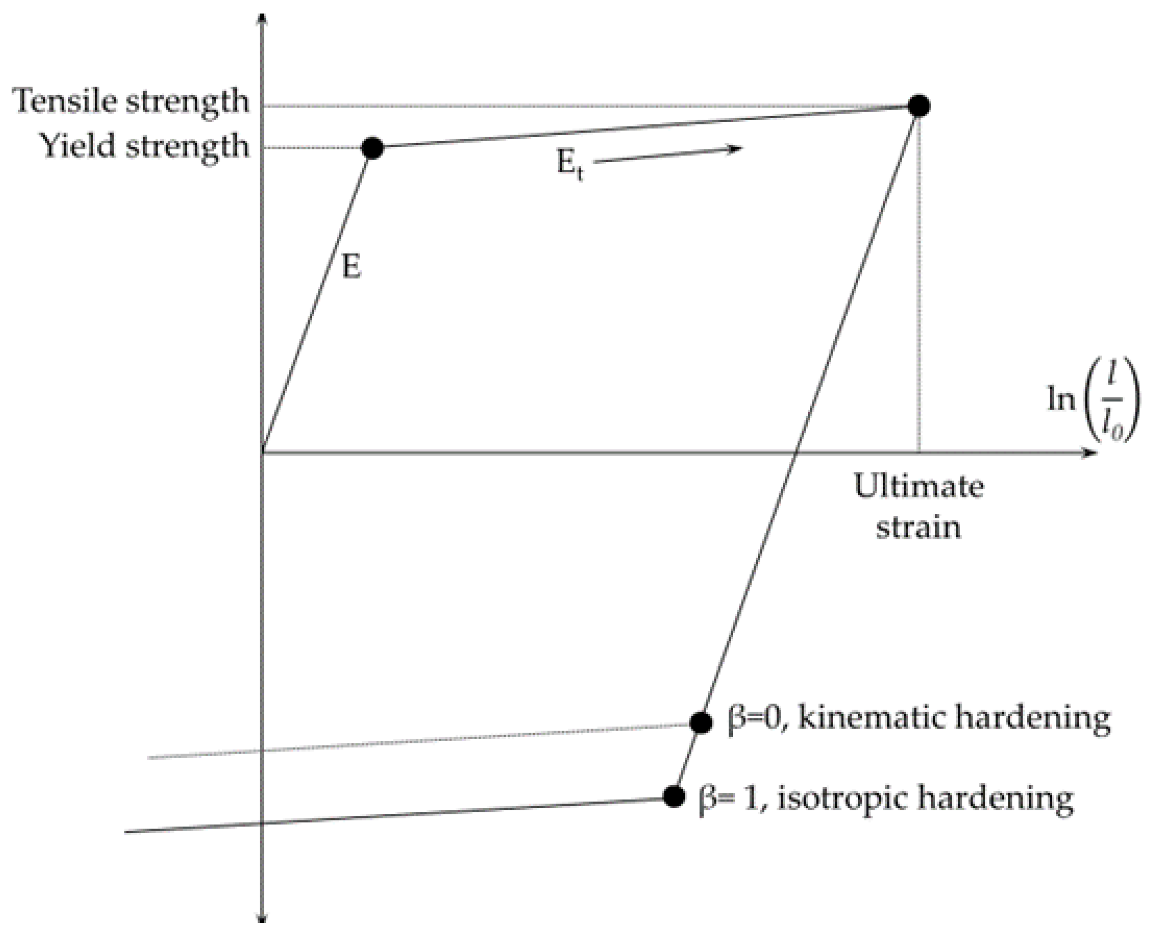
ϵelast = fyk/E,
2.5. Discussion of State of the Art on Blast Load Analyses of Tank Structures
- OL (operating level)/OB (operating basis): After impact by a blast load event, the tank structure will remain operational.
- CL (contingency level)/SS (safe shut-down): After impact by a blast load event, the tank structure may be damaged but without the loss of overall integrity and containment.
3. Simulation Model for Numerical Analyses
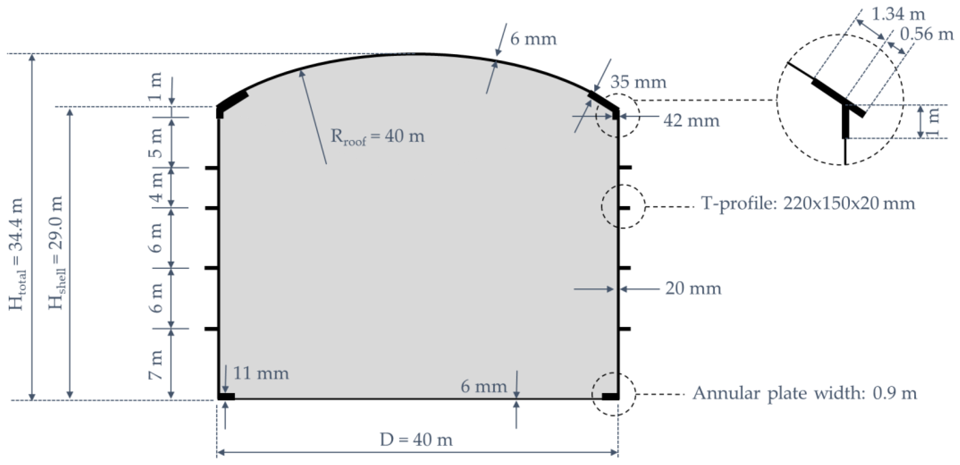
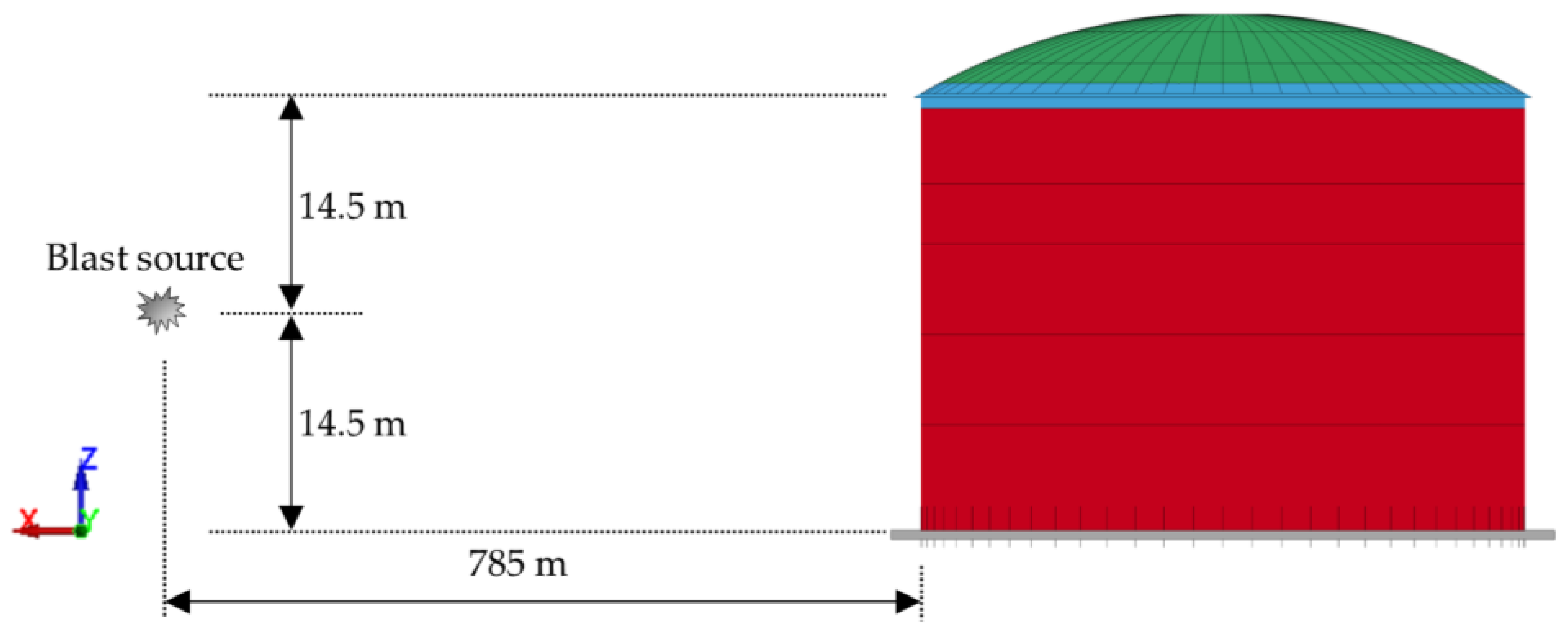
3.1. Representative Geometry
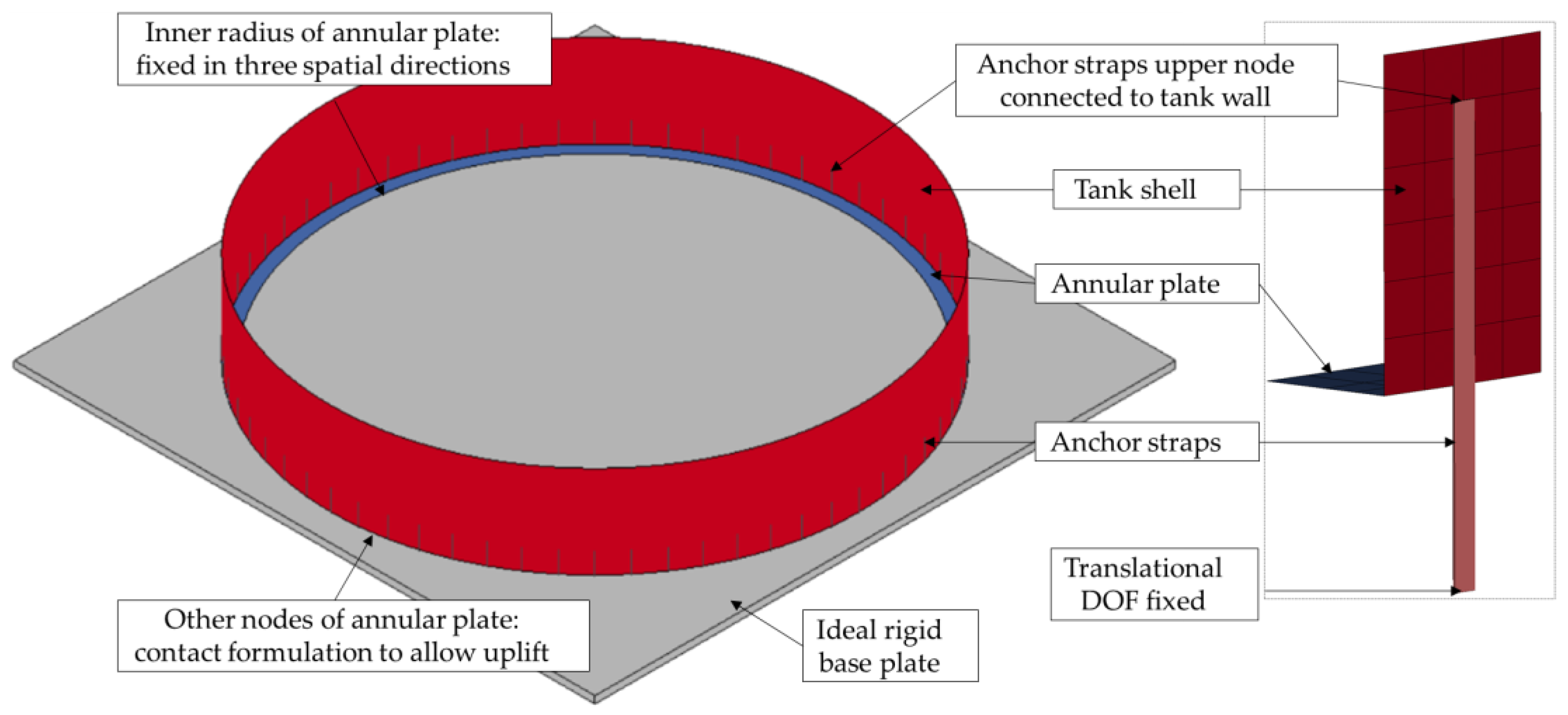
3.2. Numerical Model
- On the inside radius of the annular plate, the nodes are fixed in the three directions of translation. This represents the fixing effect of the bottom plate between the rigid foundation and the load of the inner tank.
- A contact definition between the ground and the other node of the annular plate allows uplift of the nodes but not penetration.
- The upper end of each anchor strip is connected to the tank wall via congruent nodes. The displacement degrees of freedom of the lower nodes of the anchor strips are locked in the three translational directions.
3.3. Material Constitutive Models
3.4. Blast Load
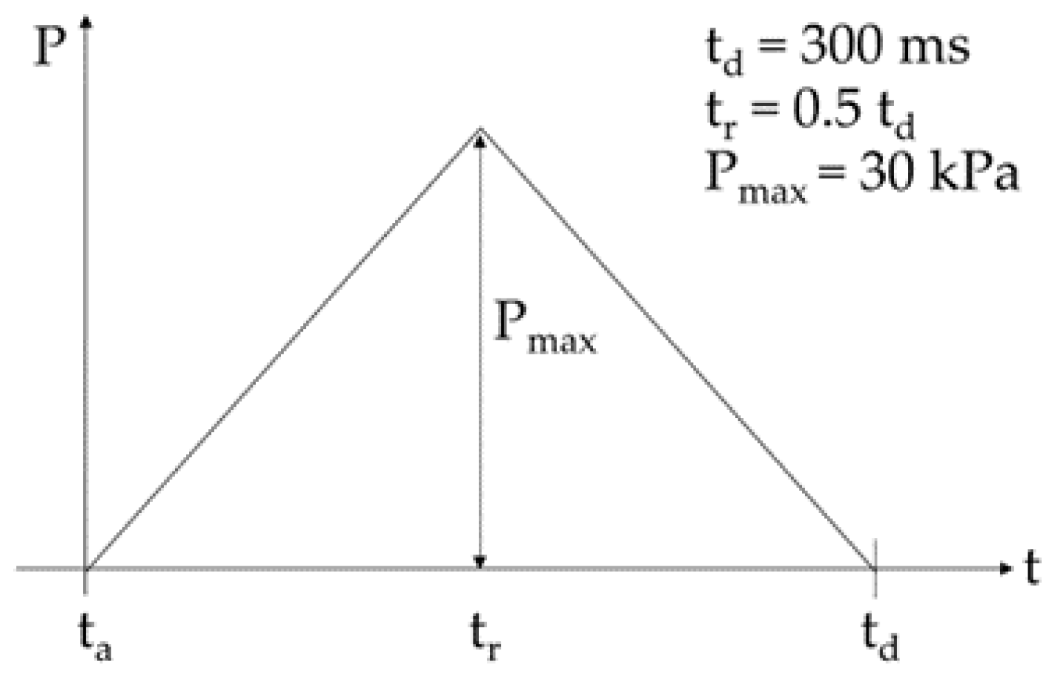
- The maximal peak reflected pressure is set to 30 kPa; the positive phase duration of the pressure wave is defined with 300 ms. The impulse amounts to 4500 kPa ms.
- With the maximal peak reflected pressure of 30 kP, the scaled distance is calculated as Z = 8.365 m/kg1/3 according to Jeon et al. [56].
- With impulse equality (Iref = 4500 kPa ms), the blast equation of [56] and Equation (1), a distance R and equivalent TNT-mass W can be determined: R = 785 m, W = 826.44 to.
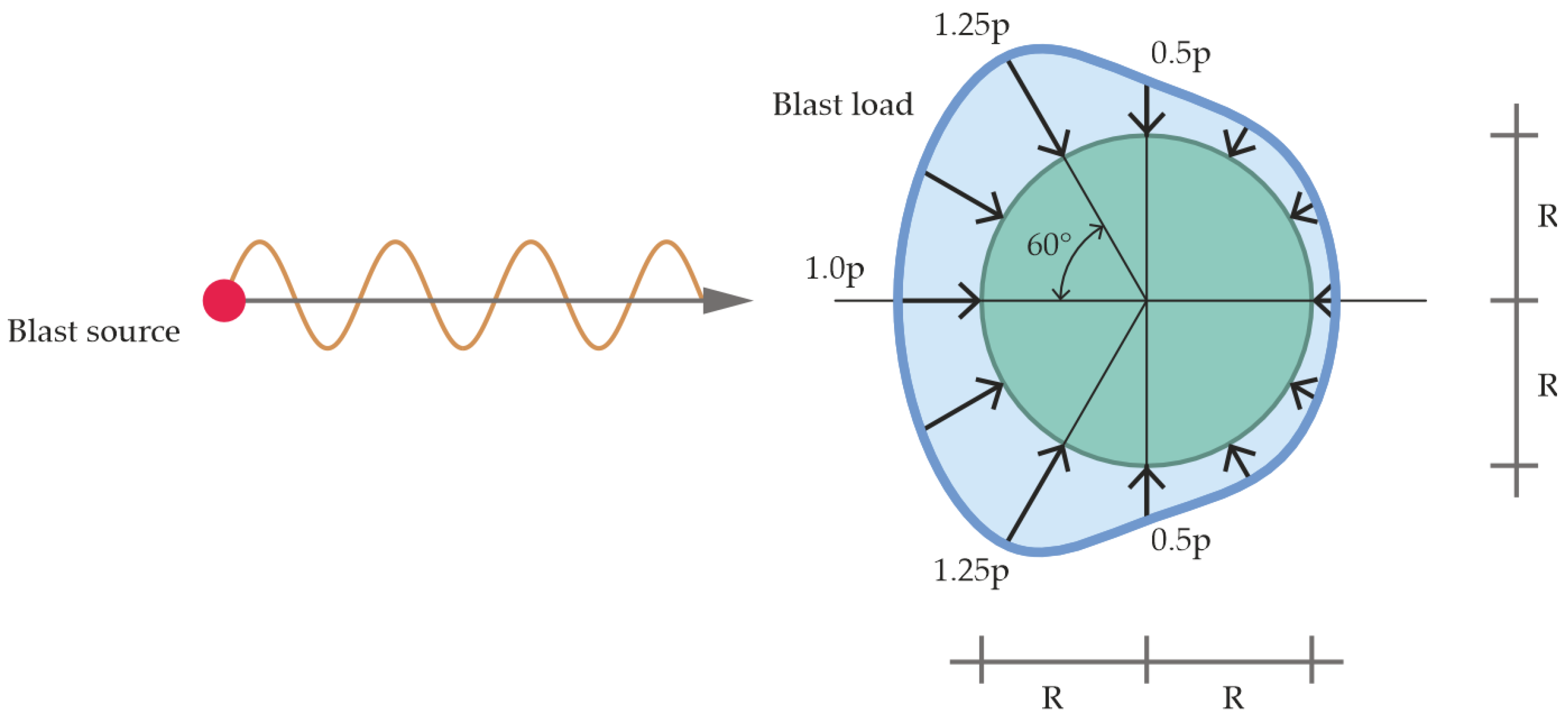
- An explosion scenario is therefore established. In this contribution, the blast source is set to a point in the positive x-direction as seen from the center of the tank (Figure 10). In relation to the height of the tank, a position halfway up the cylinder is selected. For each element of the tank structure, the corresponding scaled distance Z is determined.
- For each element of the tank structure, the angle of incidence is determined.
- For each element of the tank structure, the peak reflected pressure, peak incident pressure, time of arrival of the pressure wave and positive pressure phase duration are determined according to the modified blast equation proposed by Jeon et al. [56]. The effective pressure for each element is determined according to Equation (3).
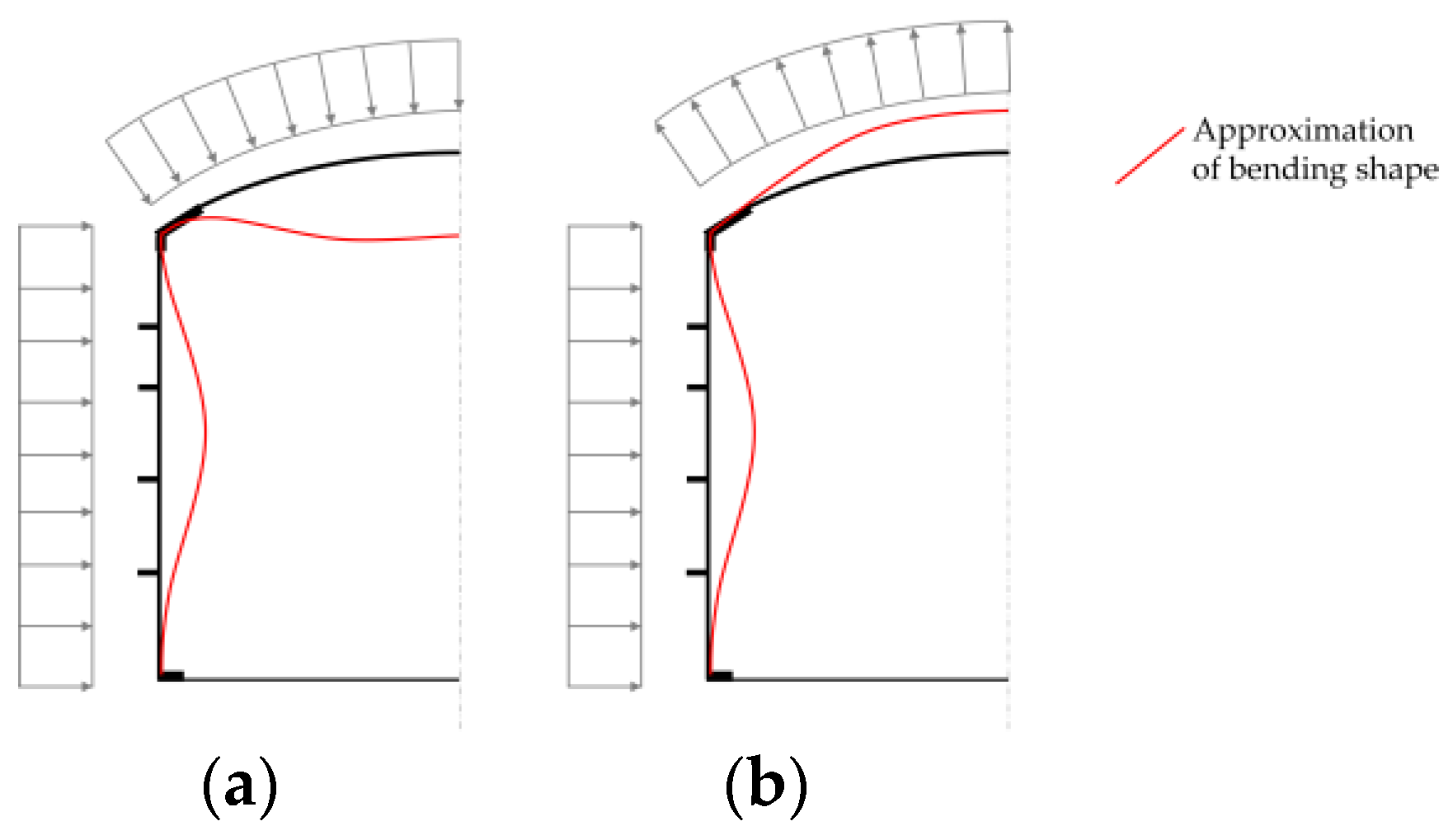
3.5. Calculation Approach
- Roof compression load;
- Roof suction load.
- A uniform peak pressure amplitude of 30 kPa to one half of the tank model. In this easily applicable approach, pressure wave propagation effects related to the decrease in the peak pressure explained in Section 2.2 are neglected. The peak pressure of 30 kPa is applied to each shell element of the blast-loaded side of the simulation model according to the proposal of [31] depicted in Figure 3. The rear side remains unloaded.
- Consideration of varying pressure amplitude depending on scaled distance and angle of incidence according to the procedure is described in Section 3.4. In this more accurate but also more elaborate approach, the peak reflected pressure, peak incident pressure, and positive phase duration are determined for each shell element of the simulation model. The effective pressure according to Equation (3) is applied to each shell element.
- A simplified bilinear approach (BL);
- A Johnson–Cook material formulation (JC) considering strain rate effects.
4. Results
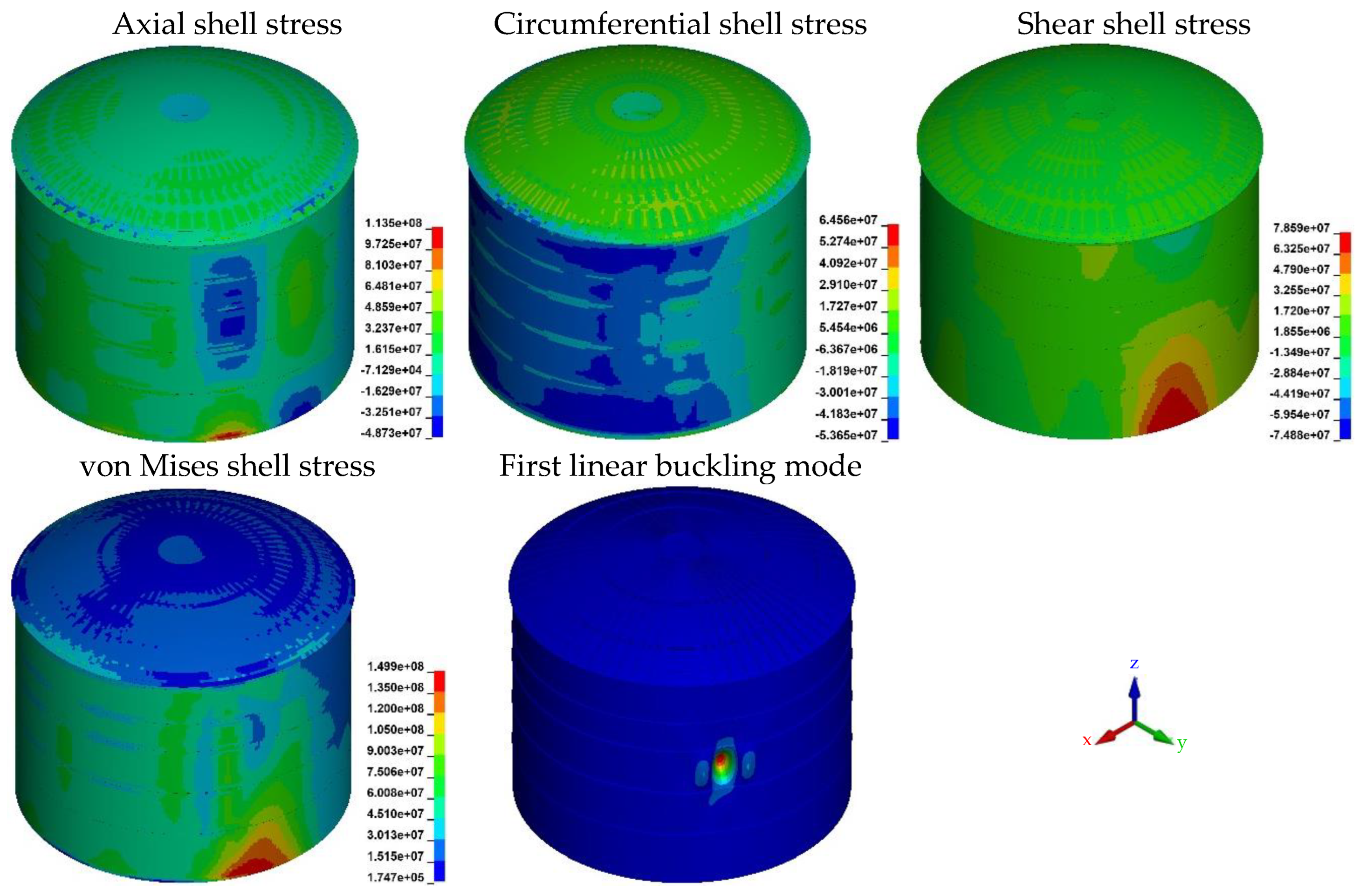
4.1. Static Simulation
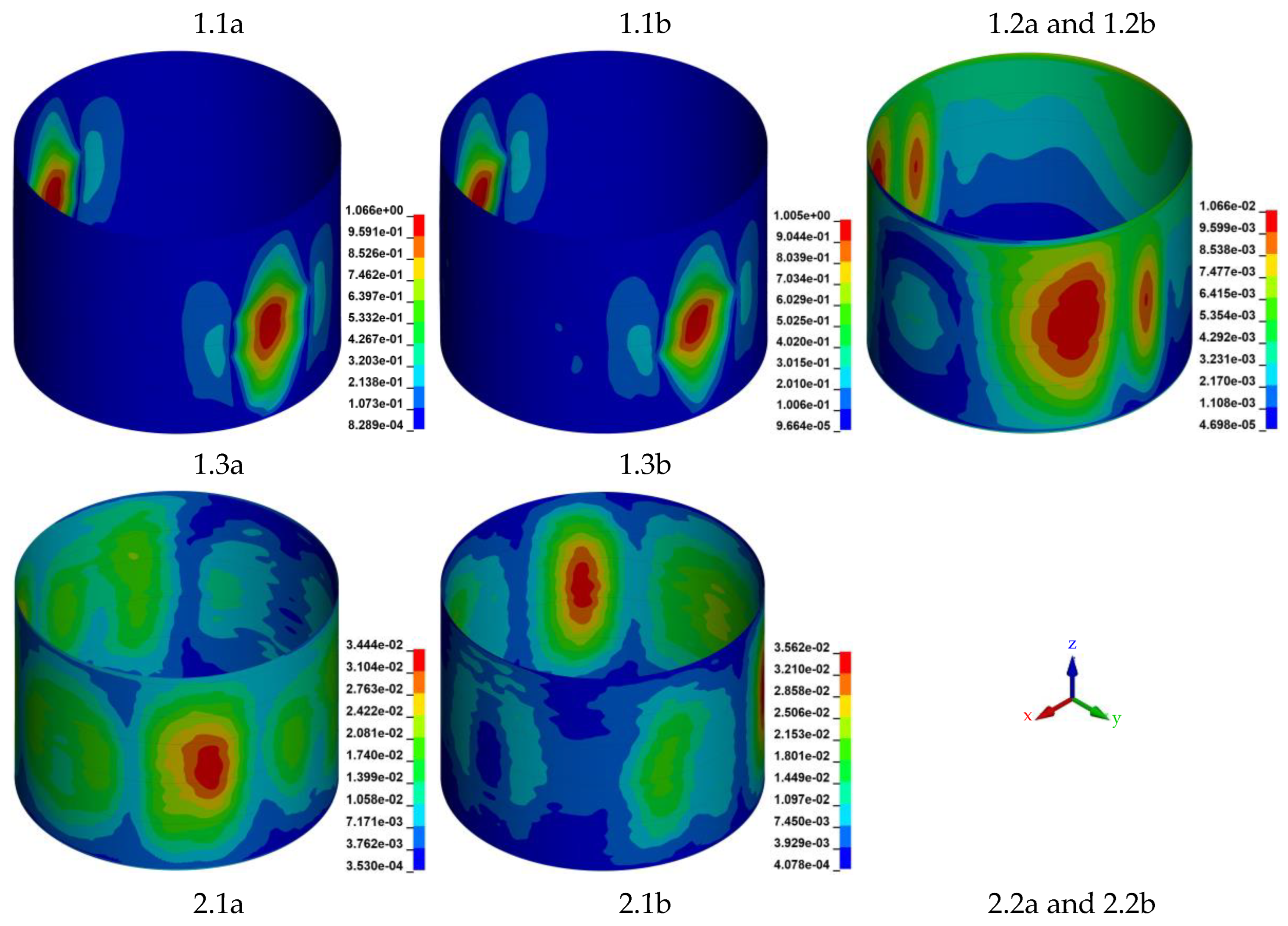
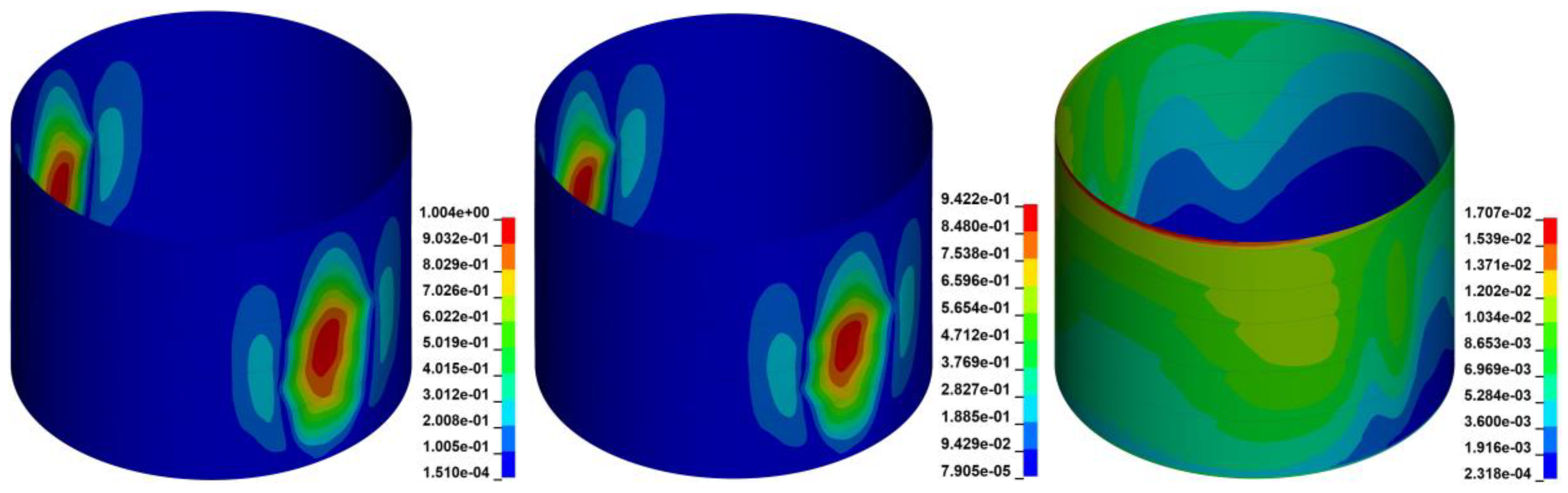
4.2. Dynamic Simulations
- Frontal tank wall: the tank wall in the direction of the explosion source.
- Tank wall sides: the tank wall parallel to the direction of the explosion source.
- Tank rear wall: the tank wall on the side facing away from the explosion pressure wave.
5. Discussion
6. Recommendation and Outlook
7. Conclusions
Author Contributions
Funding
Institutional Review Board Statement
Informed Consent Statement
Data Availability Statement
Conflicts of Interest
References
- Valera-Medina, A.; Bañares Alcántara, R. Techno-Economic Challenges of Green Ammonia as Energy Vector; Academic Press: London, UK, 2020; ISBN 9780128205600. [Google Scholar]
- Devarasetti, H. OCI to Expand Ammonia Import Terminal at Port of Rotterdam. Ship Technology [Online], 16 June 2022. Available online: https://www.ship-technology.com/news/oci-ammonia-import-terminal-port-of-rotterdam/?cf-view (accessed on 29 December 2023).
- Lambertz, L. Import of Green Energy: RWE Builds Ammonia Terminal in Brunsbüttel; Release 18 March 2022; RWE Press: Essen, Germany, 2022. [Google Scholar]
- Hanseatic Energy Hub. LNG-Terminal Stade. Available online: https://www.hanseatic-energy-hub.de/ (accessed on 29 December 2023).
- API STD 625; Tank Systems for Refrigerated Liquefied Gas Storage. American Petroleum Institute: Washington, DC, USA, 2021.
- API STD 620; Design and Construction of Large, Welded, Low-Pressure Storage Tanks. American Petroleum Institute: Washington, DC, USA, 2021.
- DIN EN 14620-1; Design and Manufacture of Site Built, Vertical, Cylindrical, Flat-Bottomed Steel Tanks for the Storage of Refrigerated, Liquefied Gases with Operating Temperatures between 0 °C and −165 °C—Part 1: General. Beuth Verlag: Berlin, Germany, 2006.
- DIN EN 14620-2; Design and Manufacture of Site Built, Vertical, Cylindrical, Flat-Bottomed Steel Tanks for the Storage of Refrigerated, Liquefied Gases with Operating Temperatures between 0 °C and −165 °C—Part 2: Metallic Components. Beuth Verlag: Berlin, Germany, 2006.
- DIN EN 14620-3; Design and Manufacture of Site Built, Vertical, Cylindrical, Flat-Bottomed Steel Tanks for the Storage of Refrigerated, Liquefied Gases with Operating Temperatures between 0 °C and −165 °C—Part 3: Concrete Components. Beuth Verlag: Berlin, Germany, 2006.
- DIN EN 14620-4; Design and Manufacture of Site Built, Vertical, Cylindrical, Flat-Bottomed Steel Tanks for the Storage of Refrigerated, Liquefied Gases with Operating Temperatures between 0 °C and −165 °C—Part 4: Insulation Components. Beuth Verlag: Berlin, Germany, 2006.
- DIN EN 14620-5; Design and Manufacture of Site Built, Vertical, Cylindrical, Flat-Bottomed Steel Tanks for the Storage of Refrigerated, Liquefied Gases with Operating Temperatures between 0 °C and −165 °C—Part 5: Testing, Drying, Purging and Cool-down. Beuth Verlag: Berlin, Germany, 2006.
- Deutsches Institut für Normung e.V. Projects: Design and Manufacture of Site Built, Vertical, Cylindrical, Flat-Bottomed Tank Systems for the Storage of Refrigerated, Liquefied Gases with Operating Temperatures between 0 °C and −196 °C—Part 7: Specific Requirements for the Design and Construction of Tanks for the Storage of Liquefied Anhydrous Ammonia. Available online: https://www.din.de/en/getting-involved/standards-committees/natank/projects/wdc-proj:din21:320684053?destinationLanguage=&sourceLanguage= (accessed on 31 January 2024).
- Publicatiereeks Gevaarlikje Stoffen. PGS 12:2023 Versie 0.1 Fase 1 (December 2023). Available online: https://publicatiereeksgevaarlijkestoffen.nl/publicaties/online/pgs-12/2023/0-1-fase-1-december-2023#m11 (accessed on 2 February 2024).
- Departement OMGEVING. Handboek Risicoberekeningen: Richtlijnen voor Kwantitatieve Risicoanalyse, Indirecte Risico’s end Milieurisicoanalyse—Versie 3.2 dd 01/12/2022. Available online: https://omgeving.vlaanderen.be/sites/default/files/2022-12/2022%2012%2001%20-%20HBRB.pdf (accessed on 2 February 2024).
- Clancey, V.J. Diagnostic features of explosion damage. In Proceedings of the 6th International Meeting on Forensic Sciences, Edinburgh, UK, 20–26 September 1972. [Google Scholar]
- TNO Green Book. Methods for the Determination of Possible Damage: To People and Objects Resulting from Releases of Hazardous Materials; TNO Green Book: Voorburg, The Netherlands, 1989; ISBN 90-5307-052-4. [Google Scholar]
- Cooperman, A.; Garrison, J.C.; Venderley, C.H. One of a Kind: Outline How the Development of the First Double Steel, Full Containment LNG Tank Could Shake Up the LNG Industry; LNG Industry Magazine: Farnham, UK, 2022. [Google Scholar]
- LS-DYNA; Version smp d R13; A Program for Nonlinear Dynamic Analysis of Structures in Three Dimensions. Livermore Software Technology Corporation: Livermore, CA, USA, 2023.
- Riemer, M.; Schreiner, F.; Wachsmuth, J. Conversion of LNG Terminals for Liquid Hydrogen or Ammonia. Analysis of Technical Feasibility und Economic Considerations; Fraunhofer Institute for Systems and Innovation Research ISI: Karlsruhe, Germany, 2022. [Google Scholar]
- Johnson, D.M. The potential for vapour cloud explosions—Lessons from the Buncefield accident. J. Loss Prev. Process Ind. 2010, 23, 921–927. [Google Scholar] [CrossRef]
- Chang, J.I.; Lin, C.-C. A study of storage tank accidents. J. Loss Prev. Process Ind. 2006, 19, 51–59. [Google Scholar] [CrossRef]
- Taveau, J. Explosion of fixed roof atmospheric storage tanks, part 1: Background and review of case histories. Process Saf. Prog. 2011, 30, 381–392. [Google Scholar] [CrossRef]
- ASCE. Design of Blast-Resistant Buildings in Petrochemical Facilities, 2nd ed.; ASCE: Reston, VA, USA, 2011; ISBN 978-0-7844-1088-2. [Google Scholar]
- Zhang, B.Y.; Li, H.H.; Wang, W. Numerical study of dynamic response and failure analysis of spherical storage tanks under external blast loading. J. Loss Prev. Process Ind. 2015, 34, 209–217. [Google Scholar] [CrossRef]
- Jiang, Y.; Zhang, B.; Wang, L.; Wei, J.; Wang, W. Dynamic response of polyurea coated thin steel storage tank to long duration blast loadings. Thin-Walled Struct. 2021, 163, 107747. [Google Scholar] [CrossRef]
- Al-Yacouby, A.M.; Lo Hao, J.; Liew, M.S.; Ratnayake, R.M.C.; Samarakoon, S.M.K. Thin-Walled Cylindrical Shell Storage Tank under Blast Impacts: Finite Element Analysis. Materials 2021, 14, 7100. [Google Scholar] [CrossRef]
- Zhang, R.; Jia, J.; Wang, H.; Guan, Y. Shock Response Analysis of a Large LNG Storage Tank Under Blast Loads. KSCE J. Civ. Eng. 2018, 22, 3419–3429. [Google Scholar] [CrossRef]
- Alderman, J.A. Introduction to LNG safety. Process Saf. Prog. 2005, 24, 144–151. [Google Scholar] [CrossRef]
- Saloua, B.; Mounira, R.; Salah, M.M. Fire and Explosion Risks in Petrochemical Plant: Assessment, Modeling and Consequences Analysis. J. Fail. Anal. Preven. 2019, 19, 903–916. [Google Scholar] [CrossRef]
- Karlos, V.; Solomos, G.; Viaccoz, B. Calculation of Blast Loads for Application to Structural Components; Publications Office: Luxembourg, 2013; ISBN 978-92-79-35158-7. [Google Scholar]
- Mittal, V.; Chakraborty, T.; Matsagar, V. Dynamic analysis of liquid storage tank under blast using coupled Euler–Lagrange formulation. Thin-Walled Struct. 2014, 84, 91–111. [Google Scholar] [CrossRef]
- UFC 3-340-02; Structures to Resist the Effects of Accidental Explosions, Unified Facilities Criteria 3-340-02 (Formerly Technical Manual TM 5-1300). U.S. Department of Defense: Washington, DC, USA, 2008.
- American Institute of Chemical Engineers. Guidelines for Vapor Cloud Explosion, Pressure Vessel Burst, BLEVE, and Flash Fire Hazards, 2nd ed.; Wiley: Hoboken, NJ, USA, 2010; ISBN 978-0-470-25147-8. [Google Scholar]
- Sharma, R.K. A violent, episodic vapour cloud explosion assessment: Deflagration-to-detonation transition. J. Loss Prev. Process Ind. 2020, 65, 104086. [Google Scholar] [CrossRef]
- Kingery, C.N.; Bulmash, C. Air Blast Parameter from TNT Sperical Air Burst and Hemispherical Surface Burst; US Army Armament and Development Center, Ballistic Research Laboratory: Aberdeen, WA, USA, 1984. [Google Scholar]
- Karlos, V.; Solomos, G.; Larcher, M. Analysis of the blast wave decay coefficient using the Kingery–Bulmash data. Int. J. Prot. Struct. 2016, 7, 409–429. [Google Scholar] [CrossRef]
- Randers-Pehrson, G.; Bannister, K.A. Airblast Loading Model for DYNA2D and DYNA3D ARL-TR-1310, Aberdeen, USA. 1997. Available online: https://apps.dtic.mil/sti/tr/pdf/ADA322344.pdf (accessed on 21 March 2024).
- Tang, M.J.; Baker, Q.A. A New Set of Blast Curves from Vapor Cloud Explosion. Process Saf. Prog. 1999, 18, 235–240. [Google Scholar] [CrossRef]
- Tang, M.; Baker, Q. Comparison of blast curves from vapor cloud explosions. J. Loss Prev. Process Ind. 2000, 13, 433–438. [Google Scholar] [CrossRef]
- van den Berg, A.C. The multi-energy method: A framework for vapour cloud explosion blast prediction. J. Hazard. Mater. 1985, 12, 1–10. [Google Scholar] [CrossRef]
- Li, X.; Chen, G.; Khan, F.; Lai, E.; Amyotte, P. Analysis of structural response of storage tanks subject to synergistic blast and fire loads. J. Loss Prev. Process Ind. 2022, 80, 104891. [Google Scholar] [CrossRef]
- Timofeev, E.; Takayama, K.; Voinovich, P. Numerical and experimental observation of three-dimensional unsteady shock wave structures. In Proceedings of the 35th Aerospace Sciences Meeting and Exhibit, Reno, NV, USA, 6–9 January 1997; American Institute of Aeronautics and Astronautics: Reston, VA, USA, 1997. [Google Scholar]
- Ding, J.; Liang, Y.; Chen, M.; Zhai, Z.; Si, T.; Luo, X. Interaction of planar shock wave with three-dimensional heavy cylindrical bubble. Phys. Fluids 2018, 30, 106109. [Google Scholar] [CrossRef]
- Drikakis, D.; Ofengeim, D.; Timofeev, E.; Voionovich, P. Computation of non-stationaly shock-wave/cylinder interaction using adaptive-grid methods. J. Fluids Struct. 1997, 11, 665–692. [Google Scholar] [CrossRef]
- Chaudhuri, A.; Hadjadj, A.; Sadot, O.; Glazer, E. Computational study of shock-wave interaction with solid obstacles using immersed boundary methods. Numer. Meth Eng. 2012, 89, 975–990. [Google Scholar] [CrossRef]
- Yasseri, S. Blast pressure distribution around large storage tanks. Blast Inf. Group 2015, 67, 133–134. [Google Scholar]
- Roetzer, J.; Douglas, H. Hazard and safety probes for LNG tanks. LNG J. 2006, 2, 27–28. [Google Scholar]
- Duong, D.H.; Hanus, J.L.; Bouazaoui, L.; Pennetier, O.; Moriceau, J.; Prod’homme, G.; Reimeringer, M. Response of a tank under blast loading—Part I: Experimental characterisation of blast loading arising from a gas explosion. Eur. J. Environ. Civ. Eng. 2012, 16, 1023–1041. [Google Scholar] [CrossRef]
- DIN EN 1993-1-6; Eurocode 3: Design of Steel Structures—Part 1-6: Strength and Stability of Shell Structures. Beuth Verlag: Berlin, Germany, 2017.
- DIN EN 1991-1-4; Eurocode 1: Actions on Structures—Part 1-4: General Actions—Wind Actions. Beuth Verlag: Berlin, Germany, 2010.
- DIN EN 10028-3; Flat Products Made of Steels for Pressure Purposes—Part 3: Weldable Fine Grain Steels, Normalized. Beuth Verlag: Berlin, Germany, 2017.
- Johnson, G.; Cook, W. A Constitutive Model and Data for Metals Subjected to Large Strains, High Strain Rates, and High Temperatures. In Proceedings of the 7th International Symposium on Ballistics, The Hague, The Netherlands, 19–21 April 1983; pp. 541–547. [Google Scholar]
- Kumar Reddy Sirigiri, V.; Yadav Gudiga, V.; Shankar Gattu, U.; Suneesh, G.; Mohan Buddaraju, K. A review on Johnson Cook material model. Mater. Today Proc. 2022, 62, 3450–3456. [Google Scholar] [CrossRef]
- Umbrello, D.; M’Saoubi, R.; Outeiro, J.C. The influence of Johnson–Cook material constants on finite element simulation of machining of AISI 316L steel. Int. J. Mach. Tools Manuf. 2007, 47, 462–470. [Google Scholar] [CrossRef]
- Barsoum, I.; Lawal, S.A.; Simmons, R.J.; Rodrigues, C.C. Failure analysis of a pressure vessel subjected to an internal blast load. Eng. Fail. Anal. 2018, 91, 354–369. [Google Scholar] [CrossRef]
- Jeon, D.; Kim, K.; Han, S. Modified Equation of Shock Wave Parameters. Computation 2017, 5, 41. [Google Scholar] [CrossRef]
- Rosin, J.; Butenweg, C.; Klinkel, S. Stability Verification for Seismically Exposed Tank Structures according to the LBA/MNA Concept; Springer: Duesseldorf, Germany, 2016. (In German) [Google Scholar]


| Name | Value | |
|---|---|---|
| Tensile strength | fuk | 490 MPa |
| Yield strength | fyk | 355 MPa 1 345 MPa 2 |
| Ultimate strain | ϵB | 22% |
| Modulus of elasticity | E | 212 GPa |
| Density | ρ | 7.82 t/m3 |
| Name | Value | |
|---|---|---|
| Hardening parameter | β | 0.5 |
| Material parameter | A | 345 MPa |
| Material parameter | B | 51 MPa |
| Material parameter | N | 0.26 |
| Material parameter | C | 0.014 |
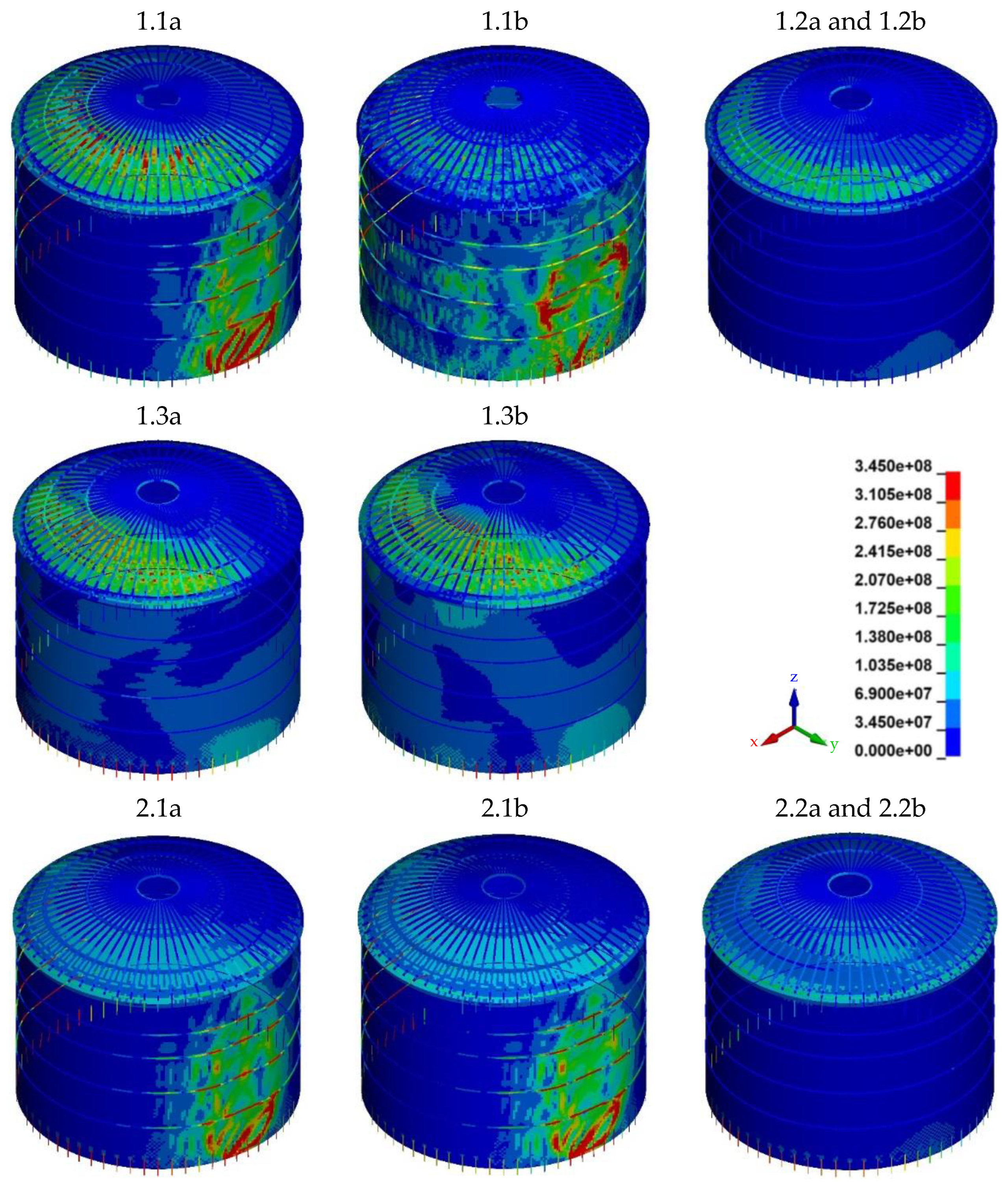
| Simulation | Roof Load | Load to the Overall Structure | Material Formulation |
|---|---|---|---|
| 0 | - | Varying pressure amplitude depending on tank’s angle of circumference, static | Linear (*MAT001) |
| 1.1a | Compression | Uniform pressure amplitude of 30 kPa to one half of tank shell and roof | Bilinear (*MAT003) |
| 1.1b | Compression | Uniform pressure amplitude of 30 kPa to one half of tank shell and roof | Johnson–Cook (*MAT098) |
| 1.2a | Compression | Varying pressure amplitude depending on scaled distance and angle of incidence | Bilinear (*MAT003) |
| 1.2b | Compression | Varying pressure amplitude depending on scaled distance and angle of incidence | Johnson–Cook (*MAT098) |
| 1.3a | Compression | Shock wave, load application via LBE | Bilinear (*MAT003) |
| 1.3b | Compression | Shock wave, load application via LBE | Johnson–Cook (*MAT098) |
| 2.1a | Suction | Uniform pressure amplitude of 30 kPa to one half of tank shell and roof | Bilinear (*MAT003) |
| 2.1b | Suction | Uniform pressure amplitude of 30 kPa to one half of tank shell and roof | Johnson–Cook (*MAT098) |
| 2.2a | Suction | Varying pressure amplitude depending on scaled distance and angle of incidence | Bilinear (*MAT003) |
| 2.2b | Suction | Varying pressure amplitude depending on scaled distance and angle of incidence | Johnson–Cook (*MAT098) |
| Maximal von Mises Stress (MPa) | Maximal Deformation (mm) | Maximal Plastic Strain (%) | |||||||||
|---|---|---|---|---|---|---|---|---|---|---|---|
| Sim | Shell | Roof | Beam | Anchor | Shell | Roof | Uplift a | Shell | Roof | Beam | Anchor |
| 1.1a | 352 | 346 | 356 | 362 | 1089 b | 109 | 79 | 1.444 | 0.249 | 1.510 | 1.919 |
| 1.1b | 493 | 431 | 503 | 505 | 1044 b | 106 | 61 | 0.904 | 0.156 | 1.160 | 1.160 |
| 1.2a | 115 | 233 | 124 | 121 | 11 | 57 | 6 | 0 | 0 | 0 | 0 |
| 1.2b | 115 | 233 | 124 | 121 | 11 | 57 | 6 | 0 | 0 | 0 | 0 |
| 1.3a | 175 | 345 | 345 | 345 | 34 | 82 | 11 | 0 | 0.067 | 0.114 | 0.049 |
| 1.3b | 173 | 402 | 386 | 395 | 36 | 82 | 11 | 0 | 0.028 | 0.003 | 0.019 |
| 2.1a | 350 | 228 | 358 | 360 | 1004 b | 50 | 63 | 1.129 | 0 | 1.555 | 1.650 |
| 2.1b | 476 | 227 | 494 | 501 | 949 b | 48 | 51 | 0.535 | 0 | 0.934 | 1.032 |
| 2.2a | 149 | 158 | 110 | 345 | 17 | 34 | 9 | 0 | 0 | 0 | 0.005 |
| 2.2b | 149 | 158 | 110 | 353 | 17 | 34 | 9 | 0 | 0 | 0 | 0 |
Disclaimer/Publisher’s Note: The statements, opinions and data contained in all publications are solely those of the individual author(s) and contributor(s) and not of MDPI and/or the editor(s). MDPI and/or the editor(s) disclaim responsibility for any injury to people or property resulting from any ideas, methods, instructions or products referred to in the content. |
© 2024 by the authors. Licensee MDPI, Basel, Switzerland. This article is an open access article distributed under the terms and conditions of the Creative Commons Attribution (CC BY) license (https://creativecommons.org/licenses/by/4.0/).
Share and Cite
Rosin, J.; Stocchi, A.; Bruckhaus, N.; Heyner, J.; Weidner, P.; Waas, T. Cylindrical Steel Tanks Subjected to Long-Duration and High-Pressure Triangular Blast Load: Current Practice and a Numerical Case Study. Appl. Sci. 2024, 14, 3465. https://doi.org/10.3390/app14083465
Rosin J, Stocchi A, Bruckhaus N, Heyner J, Weidner P, Waas T. Cylindrical Steel Tanks Subjected to Long-Duration and High-Pressure Triangular Blast Load: Current Practice and a Numerical Case Study. Applied Sciences. 2024; 14(8):3465. https://doi.org/10.3390/app14083465
Chicago/Turabian StyleRosin, Julia, Alessandro Stocchi, Norman Bruckhaus, Johanna Heyner, Philipp Weidner, and Till Waas. 2024. "Cylindrical Steel Tanks Subjected to Long-Duration and High-Pressure Triangular Blast Load: Current Practice and a Numerical Case Study" Applied Sciences 14, no. 8: 3465. https://doi.org/10.3390/app14083465
APA StyleRosin, J., Stocchi, A., Bruckhaus, N., Heyner, J., Weidner, P., & Waas, T. (2024). Cylindrical Steel Tanks Subjected to Long-Duration and High-Pressure Triangular Blast Load: Current Practice and a Numerical Case Study. Applied Sciences, 14(8), 3465. https://doi.org/10.3390/app14083465