
RDD-YOLO: Road Damage Detection Algorithm Based on Improved You Only Look Once Version 8


Abstract
1. Introduction
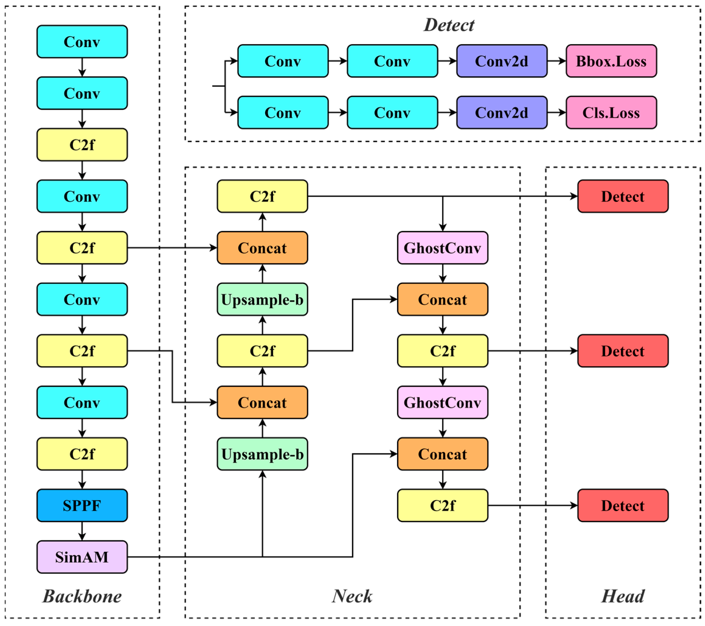
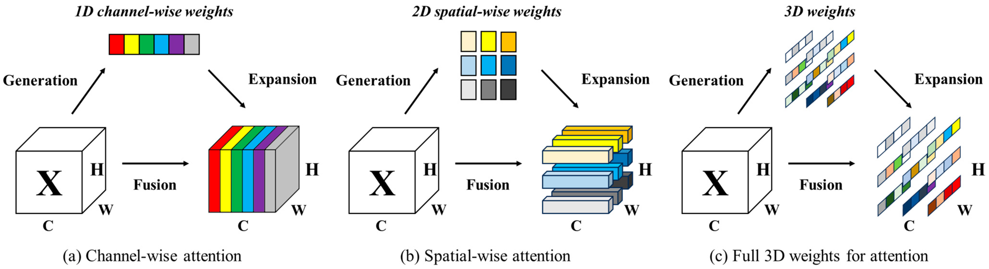
- The introduction of the SimAM [2] into the backbone filters out noise and amplifies the model’s focus on important information within the input image. This enhancement significantly improves the model’s performance and generalization ability, enhancing its ability to effectively handle road damage detection tasks.
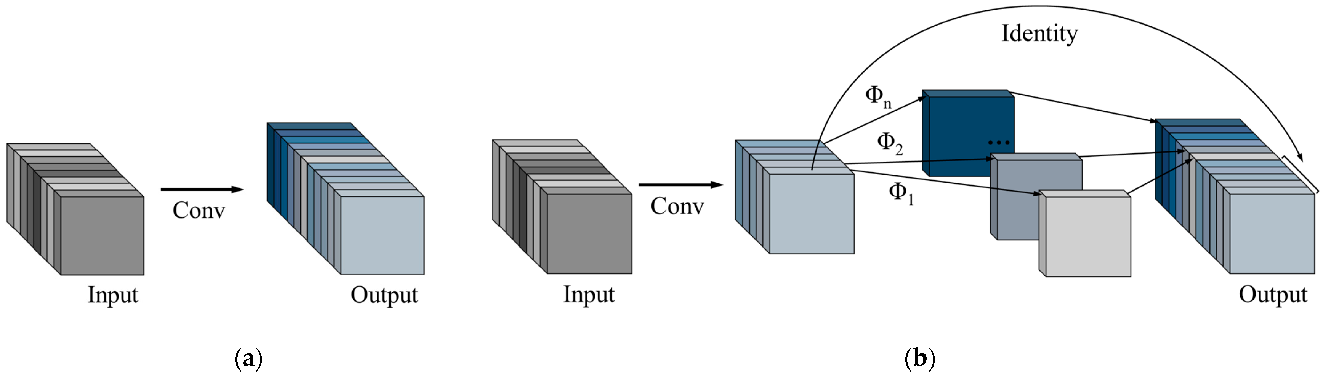
- The neck structure is enhanced by replacing traditional convolution modules with GhostConv [3]. This not only successfully reduces redundant information in the model, lowering the number of parameters and computational complexity, but also maintains the model’s outstanding performance in recognizing damage.
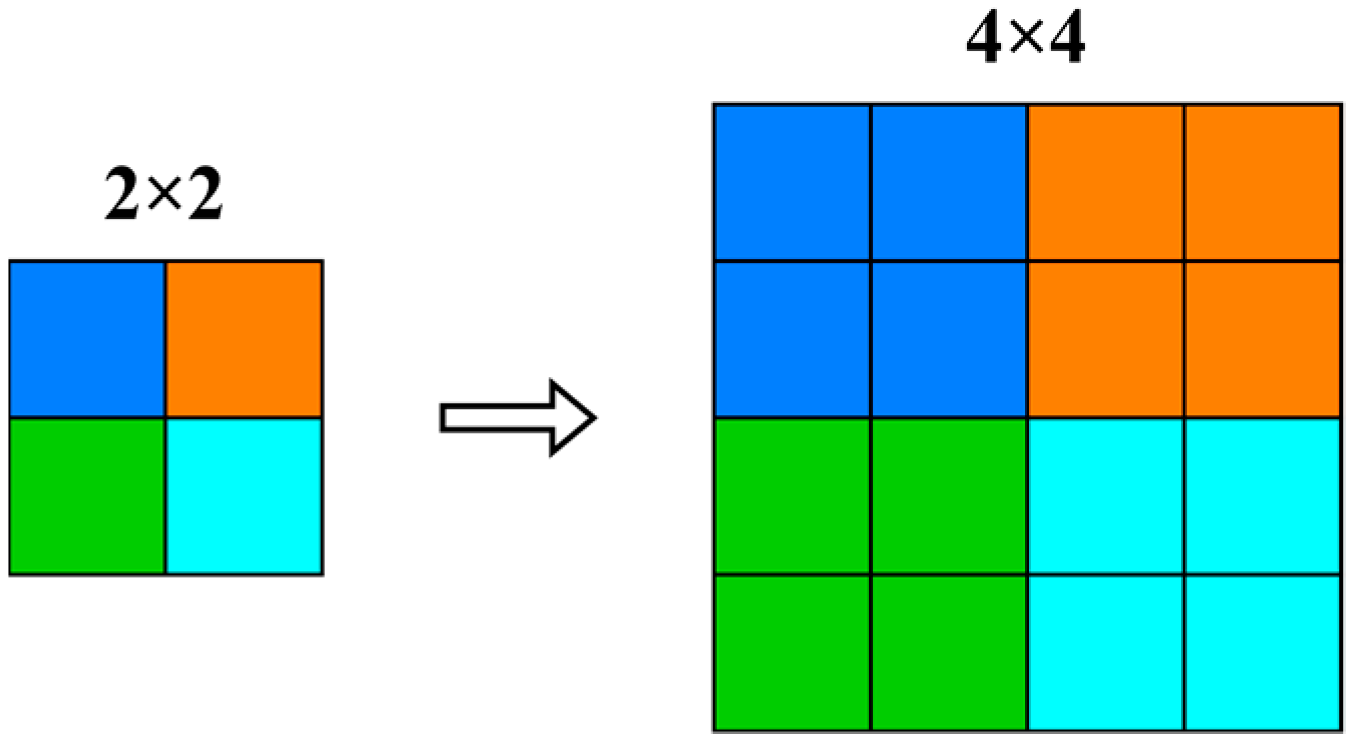
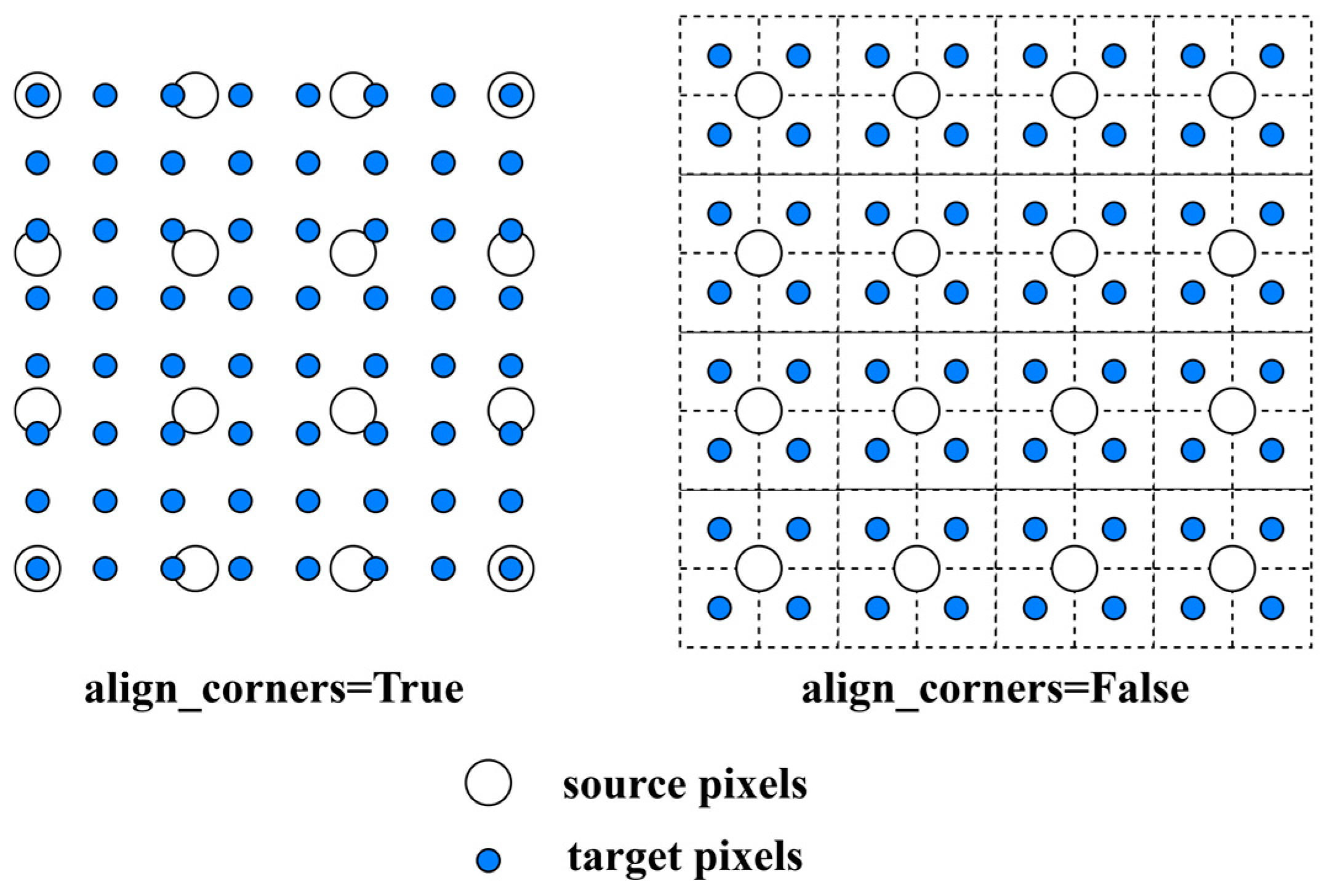
- To ensure the provision of more accurate images, the nearest interpolation in the neck is replaced with a more accurate bilinear interpolation. This modification enhances the model’s capability to retain complex details in the image, producing a clearer, more accurate output that helps minimize the impact of environmental factors on detection results.
2. Related Work
2.1. Road Damage Detection
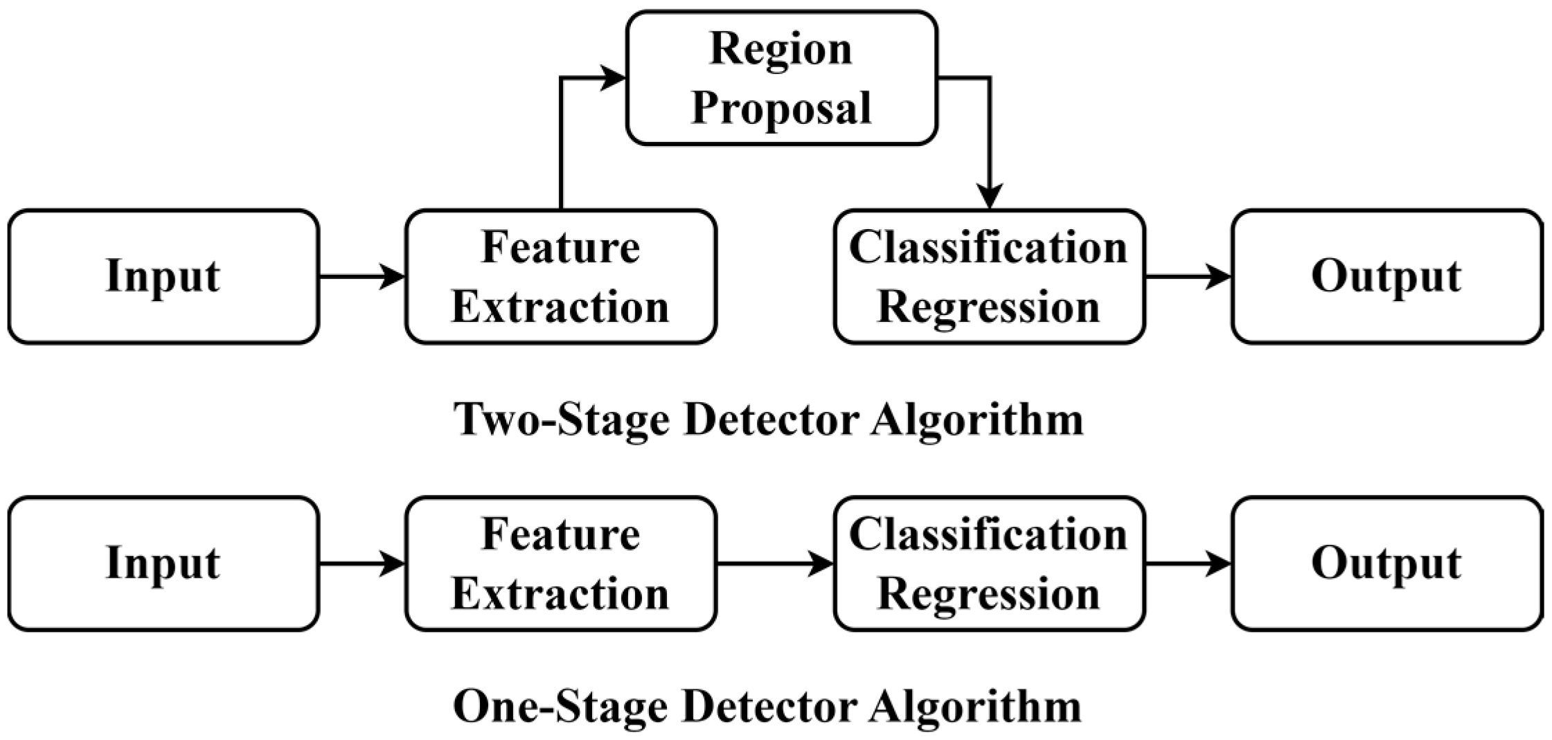
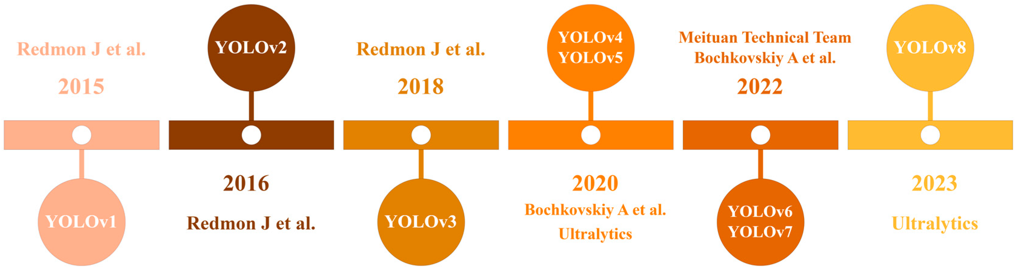
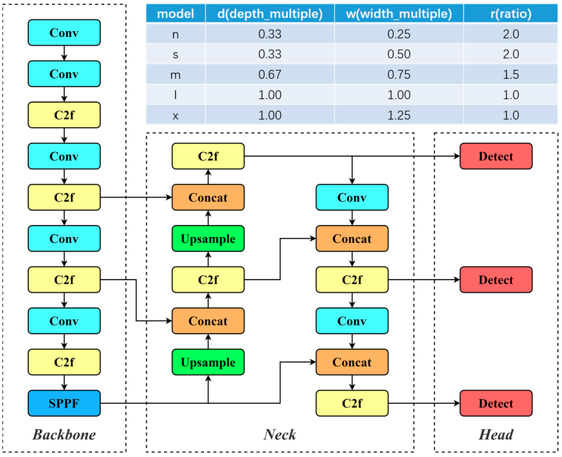
2.2. YOLO Algorithm
3. The Proposed Method
3.1. SimAM
3.2. GhostConv Convolution Module
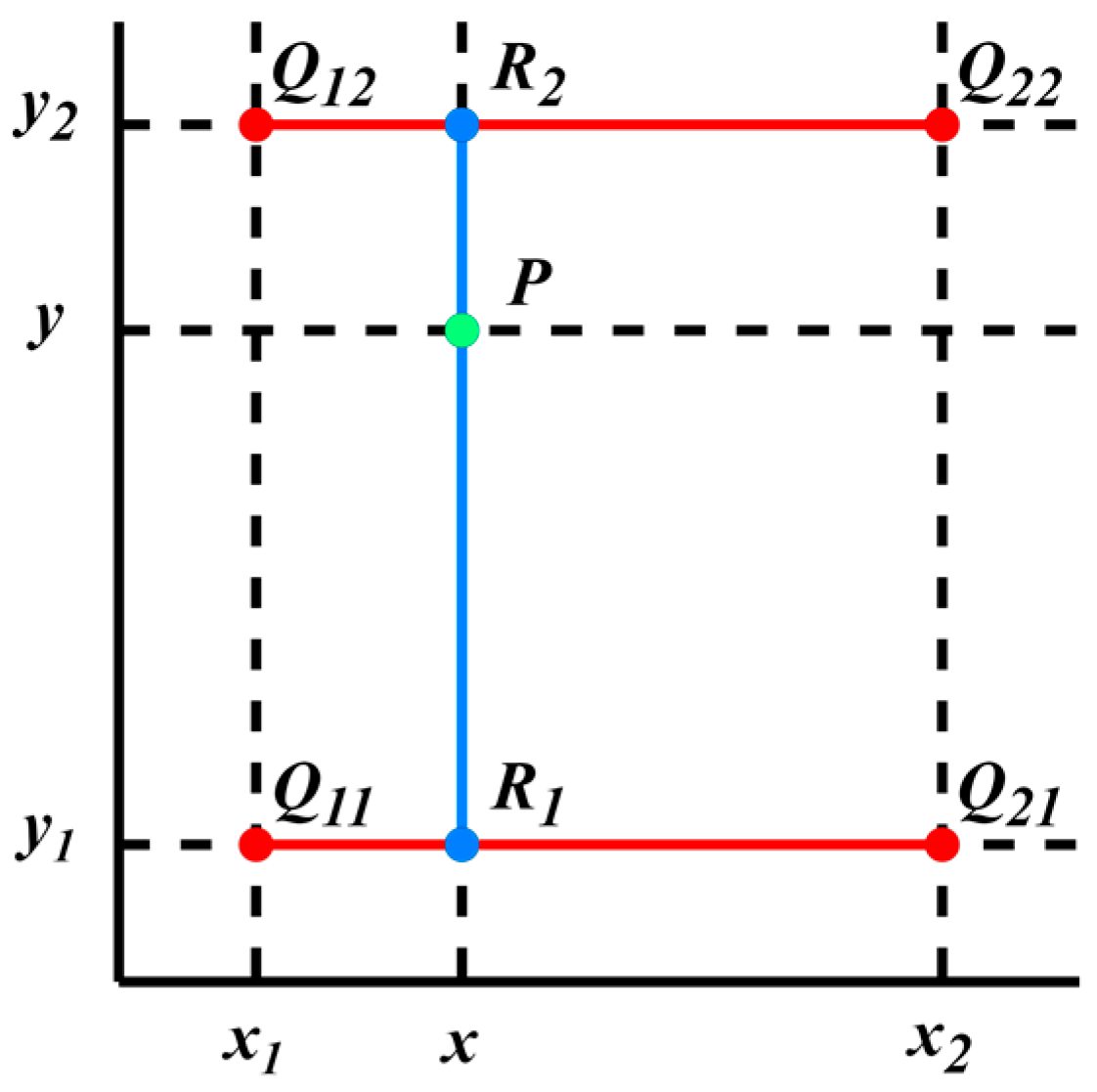
3.3. Bilinear Interpolation
4. Experimental Results and Analysis
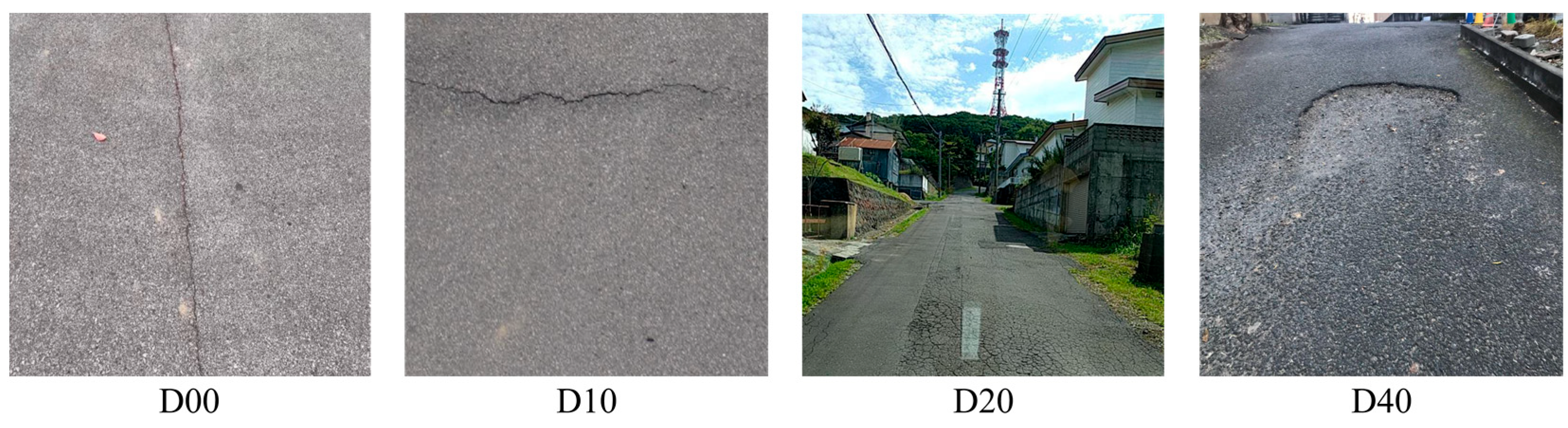
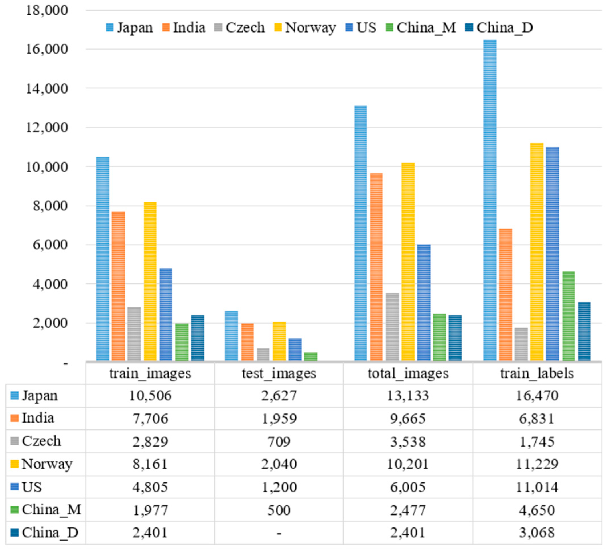
4.1. Dataset
4.2. Experimental Environment
4.3. Evaluation Metrics
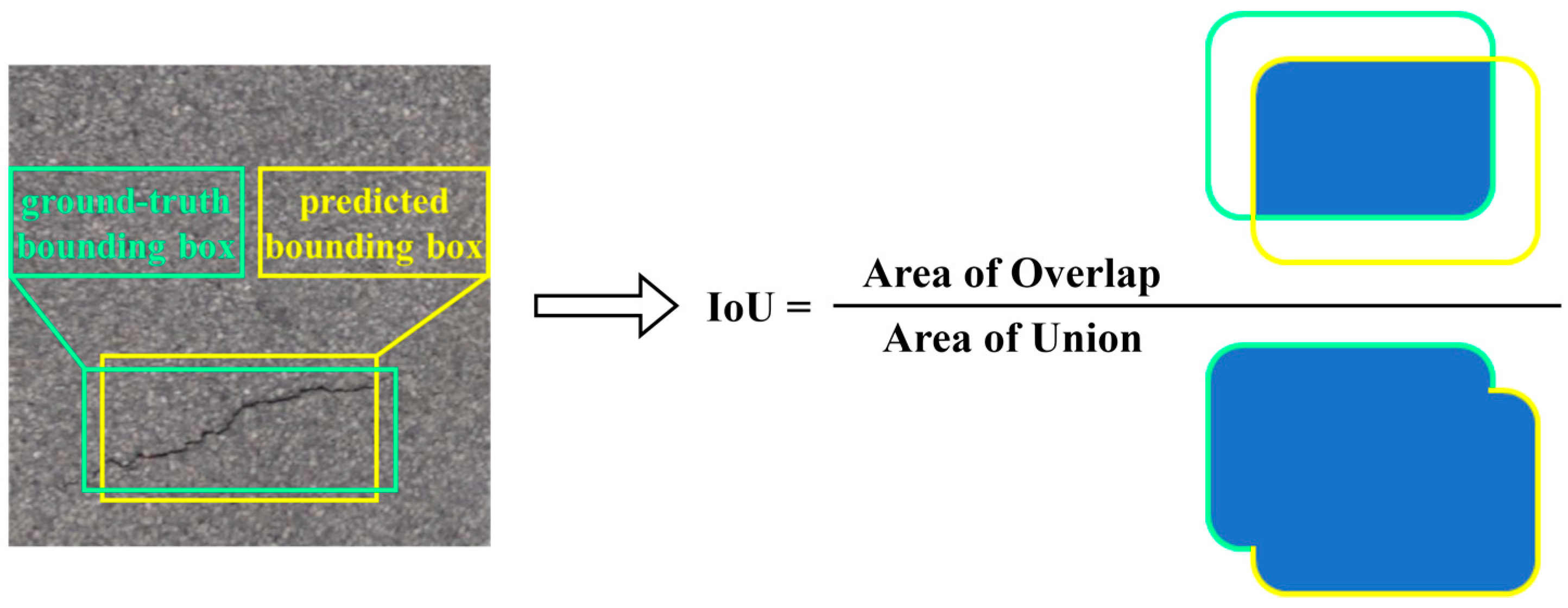
- True Positive (TP): An instance of road damage exists in the real situation and the labeling of the instance is correctly predicted, the overlap area between the predicted bounding box and the ground truth bounding box is more than 50%, and the IoU > 0.5.
- False Positive (FP): The model predicts an instance of road damage at the specific position in the image that does not exist in the ground reality of the image. FP includes cases where the predicted labels do not match the actual labels too.
- False Negative (FN): When there are instances of road damage in the real situation, but the model cannot predict the correct label or bounding box for the instance.
- Recall:
- Precision:
- F1 Score:
- AP: The precision–recall (PR) curve can be plotted based on precision and recall values, and the AP is the average value of the function over the domain of definition .
- mAP: Calculate and average the APs for each category.
- Params: The total quantity of learnable parameters in the neural network, including model weights and biases, is used to measure the spatial complexity and size of the model.
- Giga-FLOPs (GFLOPs): The quantity of billion floating-point operations performed by the model per second. GFLOPs is used to evaluate the computational complexity and efficiency of the model.

4.4. Experimental Implementation and Experimental Results
5. Conclusions
Author Contributions
Funding
Data Availability Statement
Conflicts of Interest
References
- Available online: https://baike.baidu.hk/item/%E5%85%AC%E8%B7%AF/7265058 (accessed on 3 April 2024).
- Yang, L.; Zhang, R.-Y.; Li, L.; Xie, X. SimAM: A Simple, Parameter-Free Attention Module for Convolutional Neural Networks. In Proceedings of the 38th International Conference on Machine Learning; PMLR, Virtual Event, 18–24 July 2021; pp. 11863–11874. [Google Scholar]
- Han, K.; Wang, Y.; Tian, Q.; Guo, J.; Xu, C.; Xu, C. Ghostnet: More Features from Cheap Operations. In Proceedings of the IEEE/CVF Conference on Computer Vision and Pattern Recognition, Seattle, WA, USA, 14–19 June 2020; pp. 1580–1589. [Google Scholar]
- Lim, R.S.; La, H.M.; Shan, Z.; Sheng, W. Developing a Crack Inspection Robot for Bridge Maintenance. In Proceedings of the 2011 IEEE International Conference on Robotics and Automation, Shanghai, China, 9–13 May 2011; IEEE: Piscataway, NJ, USA, 2011; pp. 6288–6293. [Google Scholar]
- Kapela, R.; Śniatała, P.; Turkot, A.; Rybarczyk, A.; Pożarycki, A.; Rydzewski, P.; Wyczałek, M.; Błoch, A. Asphalt Surfaced Pavement Cracks Detection Based on Histograms of Oriented Gradients. In Proceedings of the 2015 22nd International Conference Mixed Design of Integrated Circuits & Systems (MIXDES), Torun, Poland, 25–27 June 2015; pp. 579–584. [Google Scholar]
- Wang, G.-L.; Hu, J.; Qian, J.-G.; Wang, Y.-Q. Simulation in Time Domain for Nonstationary Road Disturbances and Its Wavelet Analysis. Zhendong Yu Chongji (J. Vib. Shock) 2010, 29, 28–32. [Google Scholar]
- Fan, Z.; Wu, Y.; Lu, J.; Li, W. Automatic Pavement Crack Detection Based on Structured Prediction with the Convolutional Neural Network. arXiv 2018, arXiv:1802.02208. [Google Scholar]
- Cao, M.-T.; Tran, Q.-V.; Nguyen, N.-M.; Chang, K.-T. Survey on Performance of Deep Learning Models for Detecting Road Damages Using Multiple Dashcam Image Resources. Adv. Eng. Inform. 2020, 46, 101182. [Google Scholar] [CrossRef]
- Kang, D.; Benipal, S.S.; Gopal, D.L.; Cha, Y.-J. Hybrid Pixel-Level Concrete Crack Segmentation and Quantification across Complex Backgrounds Using Deep Learning. Autom. Constr. 2020, 118, 103291. [Google Scholar] [CrossRef]
- Mandal, V.; Mussah, A.R.; Adu-Gyamfi, Y. Deep Learning Frameworks for Pavement Distress Classification: A Comparative Analysis. In Proceedings of the 2020 IEEE International Conference on Big Data (Big Data), Atlanta, GA, USA, 10–13 December 2020; pp. 5577–5583. [Google Scholar]
- Chen, Q.; Gan, X.; Huang, W.; Feng, J.; Shim, H. Road Damage Detection and Classification Using Mask R-CNN with DenseNet Backbone. Comput. Mater. Contin. 2020, 65, 2201–2215. [Google Scholar] [CrossRef]
- Yuan, Y.; Yuan, Y.; Baker, T.; Kolbe, L.M.; Hogrefe, D. FedRD: Privacy-Preserving Adaptive Federated Learning Framework for Intelligent Hazardous Road Damage Detection and Warning. Future Gener. Comput. Syst. 2021, 125, 385–398. [Google Scholar] [CrossRef]
- Zhang, Y.; Zuo, Z.; Xu, X.; Wu, J.; Zhu, J.; Zhang, H.; Wang, J.; Tian, Y. Road Damage Detection Using UAV Images Based on Multi-Level Attention Mechanism. Autom. Constr. 2022, 144, 104613. [Google Scholar] [CrossRef]
- Wang, J.; Gao, X.; Liu, Z.; Wan, Y. GSC-YOLOv5: An Algorithm Based on Improved Attention Mechanism for Road Creak Detection. In Proceedings of the 2023 IEEE 12th Data Driven Control and Learning Systems Conference (DDCLS), Xiangtan, China, 12–14 May 2023; IEEE: Washington, DC, USA, 2023; pp. 1664–1671. [Google Scholar]
- Ni, Y.; Mao, J.; Fu, Y.; Wang, H.; Zong, H.; Luo, K. Damage Detection and Localization of Bridge Deck Pavement Based on Deep Learning. Sensors 2023, 23, 5138. [Google Scholar] [CrossRef] [PubMed]
- Redmon, J.; Divvala, S.; Girshick, R.; Farhadi, A. You Only Look Once: Unified, Real-Time Object Detection. In Proceedings of the IEEE Conference on Computer Vision and Pattern Recognition, Las Vegas, NV, USA, 21–26 July 2016; pp. 779–788. [Google Scholar]
- Xiao, B.; Nguyen, M.; Yan, W.Q. Fruit Ripeness Identification Using YOLOv8 Model. Multimed. Tools Appl. 2024, 83, 28039–28056. [Google Scholar] [CrossRef]
- Redmon, J.; Farhadi, A. YOLO9000: Better, Faster, Stronger. In Proceedings of the IEEE Conference on Computer Vision and Pattern Recognition, Honolulu, HI, USA, 21–26 July 2017; pp. 7263–7271. [Google Scholar]
- Redmon, J.; Farhadi, A. YOLOv3: An Incremental Improvement. arXiv 2018, arXiv:1804.02767. [Google Scholar]
- Bochkovskiy, A.; Wang, C.-Y.; Liao, H.-Y.M. YOLOv4: Optimal Speed and Accuracy of Object Detection. arXiv 2020, arXiv:2004.10934. [Google Scholar]
- Hussain, M. YOLO-v1 to YOLO-v8, the Rise of YOLO and Its Complementary Nature toward Digital Manufacturing and Industrial Defect Detection. Machines 2023, 11, 677. [Google Scholar] [CrossRef]
- Li, C.; Li, L.; Jiang, H.; Weng, K.; Geng, Y.; Li, L.; Ke, Z.; Li, Q.; Cheng, M.; Nie, W.; et al. YOLOv6: A Single-Stage Object Detection Framework for Industrial Applications. arXiv 2022, arXiv:2209.02976. [Google Scholar]
- Wang, C.-Y.; Bochkovskiy, A.; Liao, H.-Y.M. YOLOv7: Trainable Bag-of-Freebies Sets New State-of-the-Art for Real-Time Object Detectors. In Proceedings of the IEEE/CVF Conference on Computer Vision and Pattern Recognition, Vancouver, BC, Canada, 18–22 June 2023; pp. 7464–7475. [Google Scholar]
- Gao, G.-S. Survey on Attention Mechanisms in Deep Learning Recommendation Models. Comput. Eng. Appl. 2022, 58, 9–18. [Google Scholar]
- Zhang, Y.; Shen, S.; Xu, S. Strip Steel Surface Defect Detection Based on Lightweight YOLOv5. Front. Neurorobot. 2023, 17, 1263739. [Google Scholar] [CrossRef] [PubMed]
- Parsania, P.-S.; Virparia, P.-V. A Comparative Analysis of Image Interpolation Algorithms. Int. J. Adv. Res. Comput. Commun. Eng. 2016, 5, 29–34. [Google Scholar] [CrossRef]
- Patel, V.; Mistree, K. A Review on Different Image Interpolation Techniques for Image Enhancement. Int. J. Emerg. Technol. Adv. Eng. 2013, 3, 129–133. [Google Scholar]
- Arya, D.; Maeda, H.; Ghosh, S.K.; Toshniwal, D.; Sekimoto, Y. RDD2022: A Multi-National Image Dataset for Automatic Road Damage Detection. arXiv 2022, arXiv:2209.08538. [Google Scholar]
- Arya, D.; Maeda, H.; Ghosh, S.K.; Toshniwal, D.; Omata, H.; Kashiyama, T.; Sekimoto, Y. Crowdsensing-Based Road Damage Detection Challenge (CRDDC’2022). In Proceedings of the 2022 IEEE International Conference on Big Data (Big Data), Osaka, Japan, 17–20 December 2022; IEEE: Washington, DC, USA, 2022; pp. 6378–6386. [Google Scholar]
- Everingham, M.; Eslami, S.M.A.; Van Gool, L.; Williams, C.K.I.; Winn, J.; Zisserman, A. The Pascal Visual Object Classes Challenge: A Retrospective. Int. J. Comput. Vis. 2015, 111, 98–136. [Google Scholar] [CrossRef]
- Arya, D.; Maeda, H.; Ghosh, S.K.; Toshniwal, D.; Mraz, A.; Kashiyama, T.; Sekimoto, Y. Transfer Learning-Based Road Damage Detection for Multiple Countries. arXiv 2020, arXiv:2008.13101. [Google Scholar]
- Arya, D.; Maeda, H.; Kumar Ghosh, S.; Toshniwal, D.; Omata, H.; Kashiyama, T.; Sekimoto, Y. Global Road Damage Detection: State-of-the-Art Solutions. In Proceedings of the 2020 IEEE International Conference on Big Data (Big Data), Atlanta, GA, USA, 10–13 December 2020; pp. 5533–5539. [Google Scholar]
- Hegde, V.; Trivedi, D.; Alfarrarjeh, A.; Deepak, A.; Ho Kim, S.; Shahabi, C. Yet Another Deep Learning Approach for Road Damage Detection Using Ensemble Learning. In Proceedings of the 2020 IEEE International Conference on Big Data (Big Data), Atlanta, GA, USA, 10–13 December 2020; pp. 5553–5558. [Google Scholar]
- Arya, D.; Maeda, H.; Ghosh, S.K.; Toshniwal, D.; Sekimoto, Y. RDD2020: An Annotated Image Dataset for Automatic Road Damage Detection Using Deep Learning. Data Briefs 2021, 36, 107133. [Google Scholar] [CrossRef]


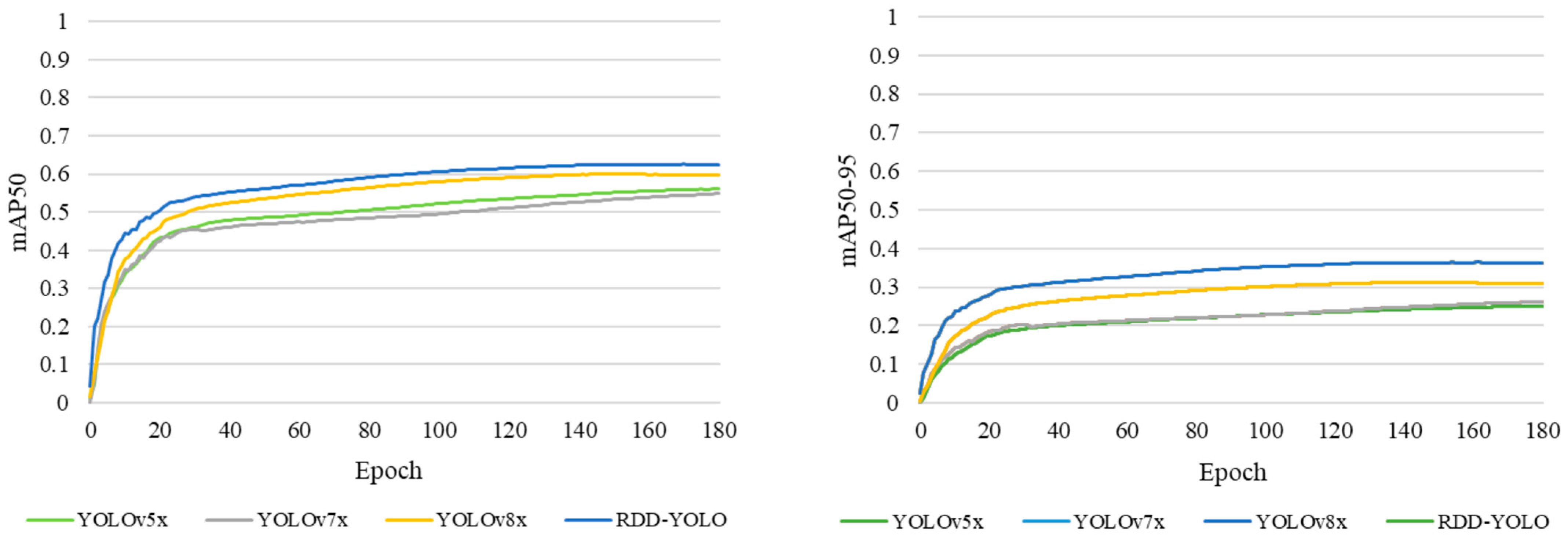
| Algorithms | Type | mAP50 | mAP50-95 |
|---|---|---|---|
| YOLOv8x | D00 | 59.3 | 33.3 |
| D10 | 59.7 | 30.1 | |
| D20 | 67.7 | 37.7 | |
| D40 | 52.9 | 23.9 | |
| ALL | 59.9 | 31.2 | |
| RDD-YOLO | D00 | 62.8 (+3.5) | 38.8 (+5.5) |
| D10 | 61.4 (+1.7) | 35.2 (+5.1) | |
| D20 | 69.2 (+1.5) | 42.3 (+4.6) | |
| D40 | 57.4 (+4.5) | 30.1 (+6.2) | |
| ALL | 62.5 (+2.6) | 36.4 (+5.2) |
| Model | F1 (India) | F1 (Japan) | F1 (United States) | F1 (6 Countries) | Params/M | GFLOPs |
|---|---|---|---|---|---|---|
| YOLOv5x | 44.9 | 63.5 | 68.0 | 63.6 | 88.5 | 220.5 |
| p-YOLOv5x | 46.8 | 64.5 | 63.2 | 60.0 | 88.5 | 220.5 |
| YOLOv7x | 42.1 | 62.0 | 68.1 | 62.6 | 70.8 | 188.9 |
| YOLOv8x | 43.6 | 66.3 | 71.5 | 66.8 | 68.2 | 258.1 |
| RDD-YOLO | 53.0 | 70.2 | 73.6 | 69.6 | 65.9 | 255.3 |
| Model | SimAM | GhostConv | Bilinear | F1 | Params/M | GFLOPs |
|---|---|---|---|---|---|---|
| YOLOv8x | 66.8 | 68.2 | 258.1 | |||
| YOLOv8-S | √ | 68.3 | 68.2 | 258.1 | ||
| YOLOv8-G | √ | 67.1 | 65.9 | 255.2 | ||
| YOLOv8-B | √ | 67.4 | 68.2 | 258.1 | ||
| RDD-YOLO | √ | √ | √ | 69.6 | 65.9 | 255.3 |
Disclaimer/Publisher’s Note: The statements, opinions and data contained in all publications are solely those of the individual author(s) and contributor(s) and not of MDPI and/or the editor(s). MDPI and/or the editor(s) disclaim responsibility for any injury to people or property resulting from any ideas, methods, instructions or products referred to in the content. |
© 2024 by the authors. Licensee MDPI, Basel, Switzerland. This article is an open access article distributed under the terms and conditions of the Creative Commons Attribution (CC BY) license (https://creativecommons.org/licenses/by/4.0/).
Share and Cite
Li, Y.; Yin, C.; Lei, Y.; Zhang, J.; Yan, Y. RDD-YOLO: Road Damage Detection Algorithm Based on Improved You Only Look Once Version 8. Appl. Sci. 2024, 14, 3360. https://doi.org/10.3390/app14083360
Li Y, Yin C, Lei Y, Zhang J, Yan Y. RDD-YOLO: Road Damage Detection Algorithm Based on Improved You Only Look Once Version 8. Applied Sciences. 2024; 14(8):3360. https://doi.org/10.3390/app14083360
Chicago/Turabian StyleLi, Yue, Chang Yin, Yutian Lei, Jiale Zhang, and Yiting Yan. 2024. "RDD-YOLO: Road Damage Detection Algorithm Based on Improved You Only Look Once Version 8" Applied Sciences 14, no. 8: 3360. https://doi.org/10.3390/app14083360
APA StyleLi, Y., Yin, C., Lei, Y., Zhang, J., & Yan, Y. (2024). RDD-YOLO: Road Damage Detection Algorithm Based on Improved You Only Look Once Version 8. Applied Sciences, 14(8), 3360. https://doi.org/10.3390/app14083360