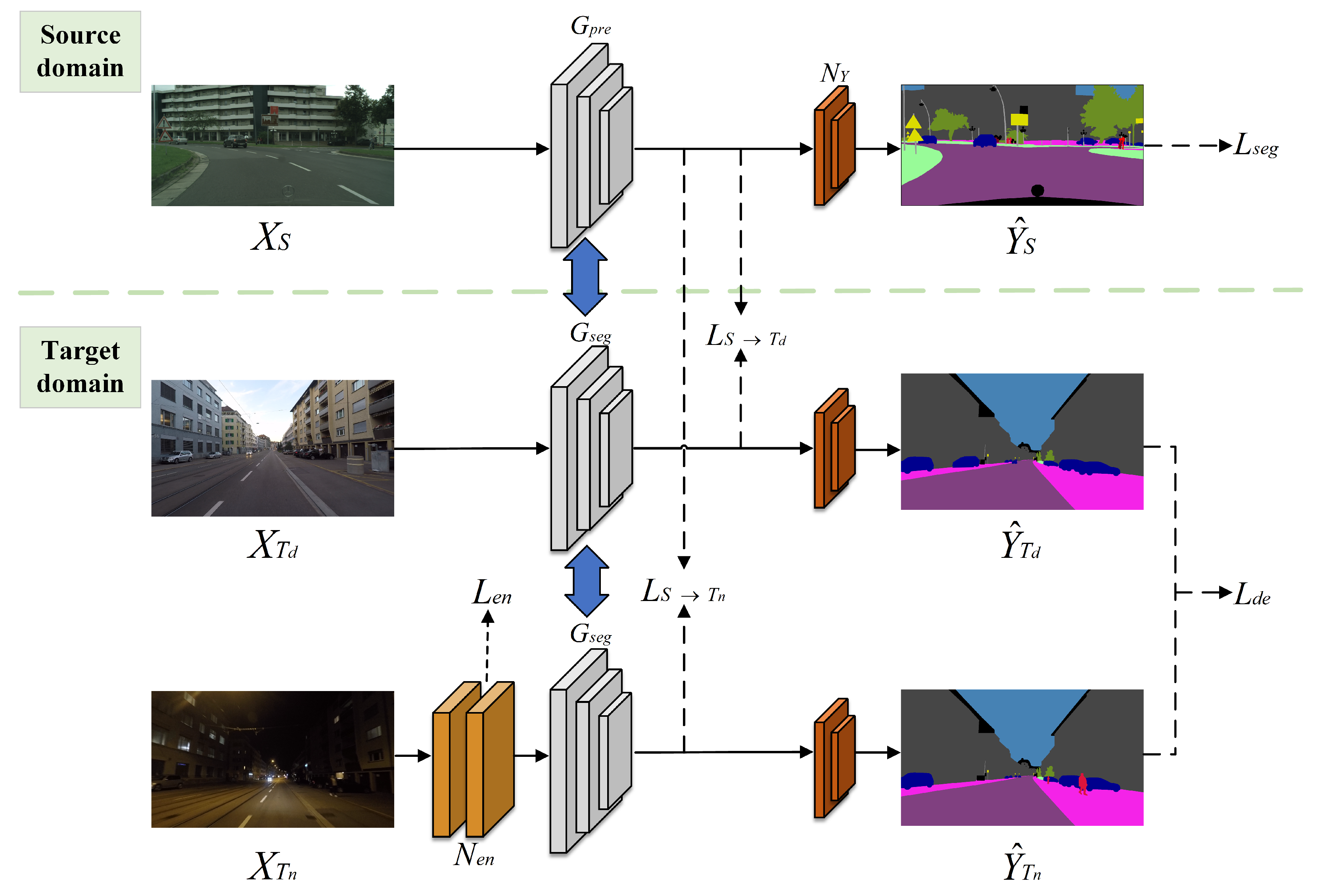
3.1. Framework Overview
The domain adaptive method proposed in this paper involves two key domains: a source domain
S for pre-training, which can be any normal lighting scene, and a target domain
containing two roughly aligned subdomains,
and
, representing daytime and nighttime scenes, respectively. In the pre-training phase, a labeled image set
from the source domain was used to optimize the semantic segmentation network parameters. Subsequently, two discriminators,
and
, were employed to bootstrap the domain adaptive model transfer from
S to
and from
S to
to efficiently model semantic segmentation of the nighttime scene
in the target domain. The domain adaptive semantic segmentation network in this paper comprises three modules: (1) a low-light image enhancement network
, (2) a pre-trained semantic segmentation network
and a transfered semantic segmentation network
, which decouples the body and edge during segmentation and provides predicted image dimensions of
, with
C denoting the total number of image categories, and (3) a segmented mask activation network
, which consists of a convolutional layer and a sigmoid normalization function, as shown in
Figure 1. The network input contains the source domain image
and the target domain images
and
, consisting of three types of domain samples. Among them,
was additionally passed through a nighttime (low-light) enhancement network
, which generated an enhancement loss
to optimize the enhancement result and brought the output closer to the daytime domain. The network uses image annotations
in the source domain
S dataset to compute the segmentation loss
and then obtains the segmentation prediction masks
and segmentation loss
by
. After that, two discriminators,
and
, perform adversarial transfer learning, and the final segmentation masks
are obtained via activating the network
, i.e.,
. The whole network guides the domain adaptive alignment of the model based on the composite total loss
.
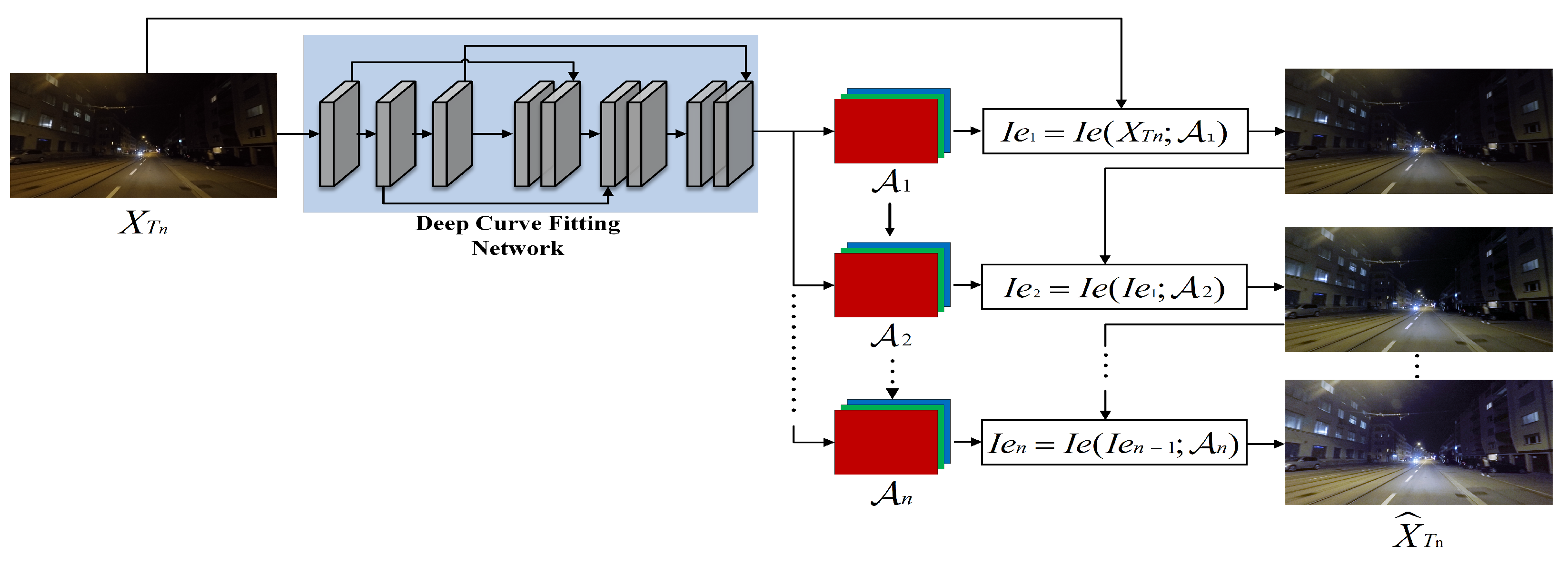
3.2. Low-Light Image Enhancement Sub-Network
In the realm of image illumination enhancement, the majority of research commonly employs methods like mapping curves or neural networks. However, this paper has the initiative to fit mapping curves with neural networks to design a low-light image enhancement sub-network. The objective was to homogenize the intensity distribution of the input image
from the nighttime target domain
and generate the enhanced image
, ensuring that the predictions of different domain samples align after passing through the segmentation network. Inspired by [
13], we utilized an iterative pixel enhancement mapping curve to adjust the brightness and contrast of the image through the pixel grayscale mapping relationship, as shown in Equation (
1).
where
x is the pixel coordinate, and the
parameter ensures that each pixel value in the enhanced image falls within the normalized range of
, preventing any loss of information due to overflow. By setting
to a value between −1 and 1, the
curve can be controlled within the range of
. For example, when
,
, i.e., each value is within
.
To adapt to more challenging low-light conditions, iterating the quadratic curve
could result in a higher-order curve. Although the higher-order curve is able to adjust the image over a wider area, it still applies a global adjustment as the
value is applied to all pixels, resulting in over-enhancement or diminution of localized regions. To solve this problem, we used a separate curve for each RGB channel of the input image to perform an iterative transformation so that each channel has a corresponding optimal
value for image enhancement, as shown in Equation (
2).
where
m, set to 8 in this paper, signifies the number of iterations and controls the curvature, and
is a parametric mapping with the same size as the given image used to represent the optimal
value for each channel. To obtain the mapping relationship among the input image and its optimal curve parameter mapping, this paper proposes a depth curve fitting network, as illustrated in
Figure 2.
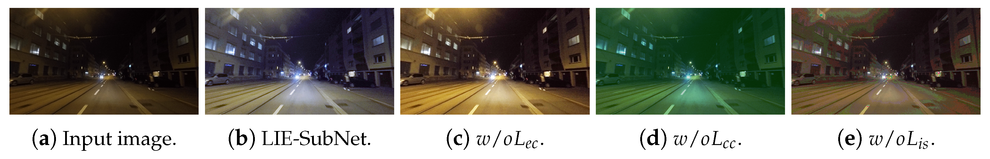
To evaluate the quality of the enhancement image, we used the following three losses to train the image enhancement network.
To suppress overexposure or underexposure of certain areas, we designed an exposure control loss
to regulate the level of exposure.
quantifies the disparity between the mean luminance value of a specific area and the intended exposure level
e.
e was set to a grayscale value in the RGB color space following existing methods [
33,
34] in this paper. This loss brought the enhancement closer to the desired exposure level, mitigated overexposure or underexposure, and hence obtained a more visualized and higher-quality image, as shown in Equation (
3).
where
V denotes the number of non-overlapping regions with a size of
, and
represents the average luminance value of localized region
V in the augmented image
.
e was set to 0.5 in the experiment.
The color constancy loss employed in this paper was based on the Gray-World [
35] color constancy assumption, which posits that each color channel is averaged as gray over the whole image. This loss rectifies potential color deviations in the enhanced image, recovers color information affected by changes in illumination, improves the quality and visual perception of the image, and determines the relationship among the three color channels, as shown in Equation (
4).
where
and
denote the average intensity values of the
a-channel and the
b-channel, respectively, in the enhanced image
, and
denotes a pair of channels,
. The smaller value of
indicates that the color of the brightened image is more balanced, and the larger
indicates that the brightened image may have the problem of color bias.
In this paper, an illumination smoothness loss [
36] was built into each curve parameter mapping
to maintain a monotonic relationship between adjacent pixels. The loss assists the model in learning that the illumination changes in the neighboring regions exhibit both consistency and smooth transition and improving image processing performance and image quality. It is shown in Equation (
5).
where
M stands for the number of iterations. Specifically,
C denotes the RGB color channels, and
.
and
denote the horizontal and vertical gradient operations, respectively. The smaller the value of
, the smoother the light of the brightened image, and vice versa, which indicates that there are mutations or artifacts in the light of the brightened image.
The total enhancement loss is shown in Equation (
6).
where
and
are hyperparameters used to balance the size of the loss and were set to 0.5 and 20 in the experiments, respectively.
Contributing to the realm of LIE-SubNet, this paper explores the combination of a set of higher-order curves that can be iterated with a deep learning network for different numbers of iterations to verify the optimal performance and enhance nighttime pixel contrast. The method reduces the domain gap among the daytime and nighttime domains without resorting to an intermediate domain or the training of multiple distinct models and feeds the segmentation network with smaller differences in illumination images.
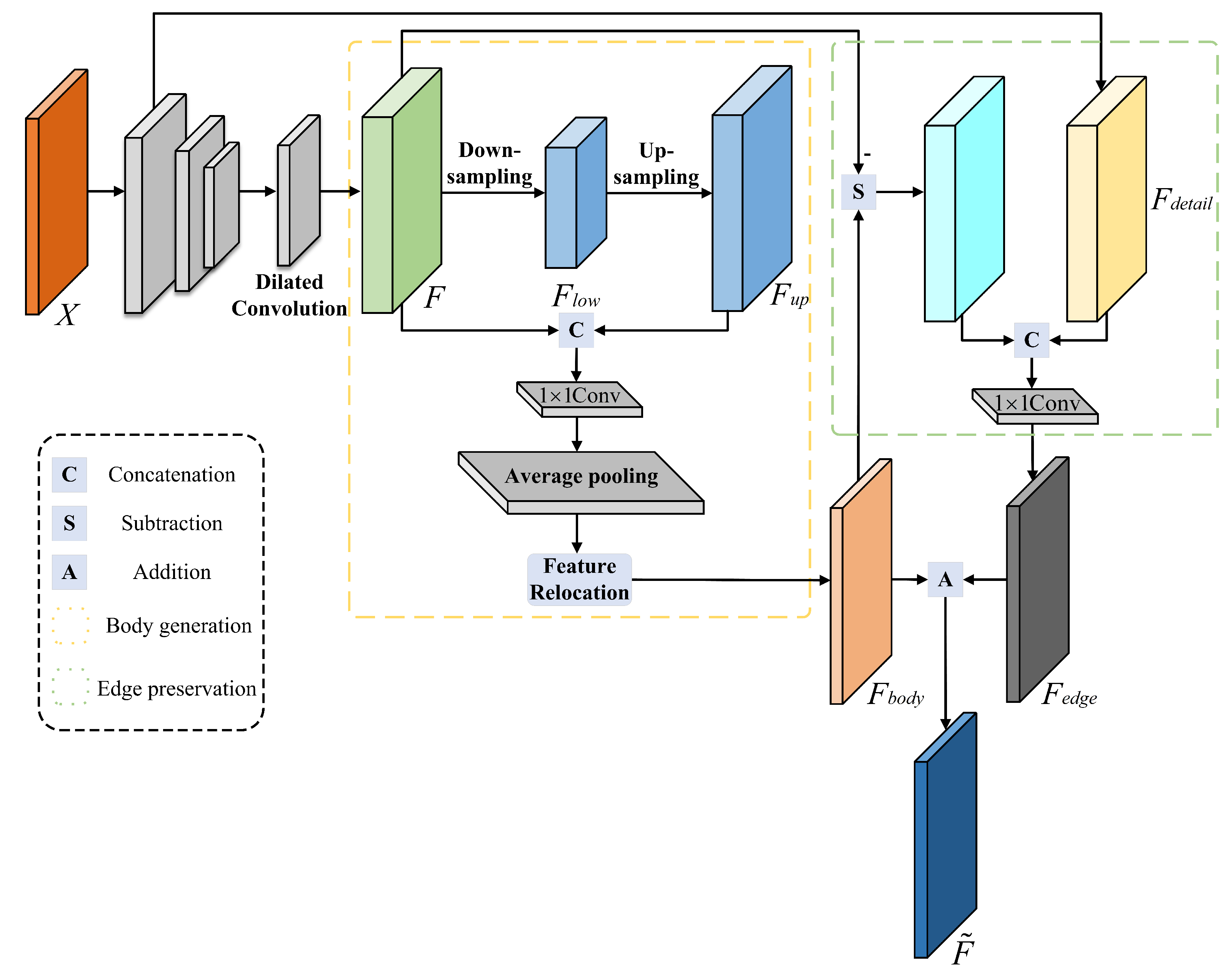
3.3. Semantic Segmentation Network for Decoupling Body and Edge
Currently, mainstream semantic segmentation methods primarily focus on enhancing the internal consistency of the object through global modeling or refining the object details along the boundaries through multi-scale feature fusion. However, it is worth noting that foreground boundary regions typically harbor more spatial detail and higher-frequency feature information. In view of this, we introduced the semantic segmentation network for decoupling body and edge, which contains a body generation branch and an edge preservation branch . Unlike previous studies, we do not require the input image’s ground truth map and trained two branches with distinct losses to predict the body feature map and edge feature map, respectively. The implementation details are described below.
Decoupling segmentation framework: In this paper, we assume that the spatial features of the image conform to the addition rule, i.e.,
. Accordingly, the body feature
can be generated first, and the edge feature
can be obtained by a specific subtraction operation. If we make
, then
, as shown in Equation (
7).
where
represents the body generation branch mapping which is used to aggregate contextual information within objects to form a distinct body for each object. On the other hand,
denotes the edge preservation branch mapping, which is designed to extract spatially detailed features from the boundary region.
Body generation branch: This branch is responsible for the generation of more consistent feature representations for pixels that are part of the same object in an image. Low-resolution feature maps typically contain low-frequency terms, with the low-spatial-frequency portion representing the image as a whole. Therefore, the low-resolution feature maps represent the most salient parts. In order to achieve this goal, as illustrated in
Figure 3,
X is the input image, and we utilized an encoder–decoder architecture after the backbone to extract
F. Specifically, the encoder downsamples
F using dilated convolution, which downsamples
F into a low-resolution representation of the low-spatial-frequency portion, denoted as
. In some cases, low-resolution features might still contain high-frequency information. We assumed that this compressed representation encapsulates the most obvious object portions and leads to rough representation which ignores details or high-frequency portions. Therefore, we used bilinear interpolation to upsample
to the same size as
F to obtain
. Then, we cascaded
F and
and used a
to adjust the channel dimensions to
to obtain
, i.e.,
, where
denotes the
convolutional layer, and
denotes the channel dimensionality join operation. This branch also contains an average pooling layer by average pooling
to generate a feature map
with a more distinct body, i.e.,
and
, where
denotes the average pooling operation.
To increase the spatial accuracy of body features in segmentation results, we first mapped each pixel
p in the default spatial grid
on
to a new pixel point
p via feature relocation. Then, we used a variable bilinear sampling mechanism [
37,
38] to approximate the value of each pixel point
p in
, i.e.,
, where
l denotes the pixels in the four fields around
p,
o is the center point, and
. In addition, to ensure smoother performance of the body feature and reduce noise and discontinuities in the prediction results, we applied the
loss [
39] to bootstrapping the body generation branch learning, as shown in Equation (
8).
where
s denotes the positional index of the element in
, and
.
Edge preservation branch: This branch is dedicated to handling high-frequency terms
in the image, where high-frequency features usually encompass more detailed edge information. To obtain the high-frequency edge feature, we subtracted the body feature
from the original feature
F, i.e.,
. Drawing inspiration from recent work on decoder design [
40], we outputted a low-level feature
through the backbone’s low layer, which served as a complement to the missing fine-detail information and augmented the high-frequency terms in
. Finally,
and
were cascaded, and then a
was used for channel adjustment to obtain
. The implementation is expressed in Equation (
9).
where
.
The edge preservation branch focuses more on edge detail features and does not require body features. Unlike the
loss, the
loss can obtain a sparse solution so that certain features have zero weight. This makes the boundary sparser and reduces unnecessary body features, contributing to an accurate boundary prediction feature map. Therefore, the
loss [
39] was utilized to guide the learning of the edge preservation branch, as shown in Equation (
10).
The final decoupling loss is:
Both the and losses complement each other by sampling pixels from different regions of the image, which was beneficial for showing the performance of the experimental results. Since the edge portion is not a large part of the overall image, is used to balance the weight of in , which was set to 0.4 in the experiments.
In this paper, acquired the body feature map and edge feature map of the input image X through the body generation branch and the edge preservation branch , respectively. Moreover, the edge features were supplemented by the high-frequency detailed features output from the lower layer of the backbone network. By employing distinct body and edge losses, the segmentation performance was enhanced, and the final segmentation map F was obtained through .
3.4. Multi-Target Domain Adversarial Learning Strategy
During the multi-target domain adversarial learning strategy, in order to ensure relatively close feature distributions after spanning different domains and to better achieve transfer alignment between source and target domains, this paper added the adversarial loss terms
and
to the outputs of the daytime domain
and the nighttime domain
, respectively. Both discriminators had identical structures, weights, and training protocols, where the identification source domain image was 1, and the target domain image was 0. The binary cross-loss function [
41] was utilized to make both
and
close to
. The antagonistic loss is defined as:
In the experiments, we trained the generator and the discriminators alternately. The generator used in the source domain
was pre-trained, and the target domain
was transfered. The objective functions of
and
are defined as:
We used cross-entropy loss to train the semantic segmentation loss of the source domain. Moreover, we introduced the small pixel reweighting
to address the small target category imbalance, as shown in Equation (
15).
where
N is the total number of image pixels,
k denotes category,
is the
norm that sums up all the pixels,
is the pixel weight,
is the prediction map
from the
kth channel of the source domain image obtained from the activation network
, i.e.,
, and
is the ground truth of the
kth category of the one-hot encoding. Specifically, for each category
k, we first defined a weight
, where
denotes the percentage of all valid pixels that are labeled as category
k in the source domain. Then,
was further normalized by
, where
and
are the mean and standard deviation of
, respectively, and
and
are preset constants to limit the value of
to positive. Finally,
was multiplied by the corresponding category channel in
to generate the weighted probability map, and then the segmentation result was yielded via
, as shown in Equation (
16).
where
.
Therefore, the total loss of the whole network is:
In summary, we designed a segmentation network for decoupling body and edge. It predicted the body and edge features of the input image, applied and losses to constrain them, respectively, and was then synthesized into a segmentation feature map. After that, two discriminators were used to distinguish different domain outputs between source and daytime image and source and nighttime image in a multi-objective domain adversarial learning strategy. Additionally, probabilistic reweighting was used to optimize the segmentation prediction for small targets.


