Abstract
The growing adoption of Building Information Modeling (BIM) within the architectural, engineering, and construction (AEC) sector raises questions about the quality of BIM data deliverables for project owners. Therefore, assessment and evaluation of such BIM data against relevant documents such as the BIM Execution Plan (BEP), the Level of Definition (LOD)/Level of Information (LOI) matrix, and quality control customized checklists become critical, especially in large construction projects. This study primarily aims to create an automated system for assessing the quality of 3D BIM model data, utilizing a proposed project quality control checklist. The automated system consists of four key elements: a BIM-based model, a Data Extraction and Analysis Module, a Data Storage Module, and a Data Visualization Module. The Data Extraction and Analysis Module extracts relevant information and parameters from BIM models to evaluate their quality against predefined checklists. Then, it transfers the information and stores the results in a database. The database is connected to an engineering project collaboration tool, ProjectWise, to automatically update and store the data in the cloud. The database is then connected to an interactive data visualization platform, Power BI, to enable automatic visualization of the generated quality assessment results of the BIM models’ data. This system was applied to a Canadian infrastructure construction project by its BIM department during the preliminary and detailed design phases. It demonstrated an average quality score (AQS) of 87.6% for the BIM models and significantly reduced failing items by around 30%. This study concludes that the system offers a robust, practical solution for enhancing the quality control process in BIM model data management, thereby aiding engineers in timely model adjustments to meet project requirements.
1. Introduction
As construction projects become more complex, the precision of information becomes increasingly crucial, which requires a considerable amount of communication and information transmission. Inadequate or insufficient data transmission often leads to project failure. The architectural, engineering, and construction (AEC) industry is experiencing a significant shift from conventional Computer-Aided Drafting (CAD) techniques to Building Information Modeling (BIM), facilitating effective data management and rapid decision making. BIM utilizes digital modeling tools to enhance the design and management of a project with greater efficiency [1]. According to Singh [2], 72% of US construction companies use BIM to decrease project costs and increase efficiency. The advancement of computer-based BIM applications enables the creation of multi-criteria parametric designs for construction projects through the use of objects characterized by their identity, attributes, and relationships. These applications facilitate the creation of automated compliance checking (ACC) for building designs [3], a development that has significantly contributed to increasing time and cost efficiencies. Code compliance in building construction refers to the adherence to local, state, and national building codes and regulations that set minimum standards for the design, construction, operation, and maintenance of buildings and structures. However, one of the main requirements of ACC is the assurance of the quality of the BIM model. Public institutions in countries such as the United States (US), the United Kingdom (UK), and Singapore have required the use of BIM in design delivery and have promoted automated checking and evaluations of BIM quality [4]. “BIM model quality” means conformance to various requirements, including LOD, procedures, specifications, and the accuracy of building information model geometries. A quality check (QC) in BIM projects involves systematically checking and verifying the accuracy and quality of BIM models and their components against relevant documents such as the BEP, LOD, LOI, etc.
The LOD in BIM projects refers to a system that defines the degree of detail and accuracy of BIM elements at different stages of design and construction. It provides a framework to specify and understand the complexity and content of BIM models at various phases, from conceptual design to construction and operation. High-quality data within BIM models are essential for the successful application of ACC, placing a considerable responsibility on designers and modelers to verify the accuracy of information before integration into the model. However, the ACC mostly deals with the regulatory requirements in building design, such as building codes, zoning regulations, environmental regulations, and health and safety. In addition to the regulatory requirements, issues related to quantity takeoff (QTO), modeling accuracy, coordination, and naming conventions also need to be addressed during the design of BIM projects since they can affect the time, cost, and deliverables of a construction project. BIM has also been proposed for use in automating high-quality quantity takeoff (QTO) [5] and automated data integration and visualization [6,7,8,9]. Valinejadshoubi et al. [6,7,8,9] developed different methods to automatically integrate, manage, and visualize monitoring information in BIM models. The open standard representations for buildings, such as the Industry Foundation Classes (IFC), facilitate extracting necessary information for the ACC and QC processes [10,11,12]. The adaptable characteristics of open BIM representations are crucial to accommodate varying information requirements within the model. Nevertheless, the difficulty in object mapping persists due to the lack of assurance that objects and their attributes within any given computable rule set can be straightforwardly aligned with an industry-standard data dictionary such as the buildingSMART data dictionary [11].
Despite the importance of 3D model data QCs, most previous research has focused only on automating the code compliance of building design, such as fire safety, structure, and sustainability [13], without adequately addressing and automating the quality and consistency of BIM data as a primary requirement for successful application of the ACC and QC processes. For efficient and precise outcomes, the data within the BIM model must be adequate, accurate, coherent, and of high quality [14]. The data provided in the design of BIM models must comply with the close-out checklists, procedures, and BEP documents to ensure appropriate and accurate project outputs. Automating the QC can speed up the process while improving the accuracy of the outputs. Therefore, an automatic QC system is needed to ensure the above-mentioned quality.
The increasing use of BIM has led to the utilization of model QC tools, which largely rely on the accuracy of the 3D design models. However, gaps remain, such as lacking BIM-based evaluation requirements [15] and automated QC processes [16,17]. This study aims to bridge these gaps by developing an automated QC system to detect inconsistencies, errors, and missing information in BIM models during the preliminary and detailed design phases of a public infrastructure construction project in Montreal, Canada.
To achieve this aim, this study sets out the following objectives:
- Developing a comprehensive BIM quality checklist for various engineering disciplines aiming to assess data quality in BIM models that impact critical aspects of a project, including naming convention, quantity and cost estimation, coordination, and modeling accuracy.
- Creating BIM-based data extraction, analysis, and storage modules utilizing programming and external data storage tools to facilitate this process.
- Introducing an easily understandable, visualization-based method for tracking passing and failing scores of each item according to BIM close-out checklists.
- Testing and evaluating the performance of the developed system across different engineering disciplines using a real-world case study project.
2. Literature Review
BIM is a digital representation of the physical and functional attributes of a facility. It is a common repository for information regarding a facility and serves as a foundation for decisions during its project lifecycle [18]. It is beneficial for quality control using building object properties, such as characteristic and relation information for various disciplines [19]. ACC is an important task that must be handled carefully during the design process. ACC is a rule-based method that controls building elements and regulations, considering the building elements’ characteristics [20,21,22].
Several researchers have explored various sides of ACC within the BIM framework. Doukari et al. [14] demonstrated an approach for automated compliance with the requirements stipulated in the project checklist using a plugin prototype. Chois and Kim [23] proposed a methodology to check the BIM data through a system for checking building codes named KBim Assess-Lite. Their system was capable of evaluating the quality of BIM data based on the IFC standard. Nguyen and Kim [24] developed a framework for a cooperative building design environment in which every participant in the project can monitor the code compliance status of their respective designs through the use of BIM technology. Villaschi et al. [25] proposed a method based on BIM to streamline the verification procedure of code compliance in construction projects. Their findings provided a real-time decision support tool enabling designers to determine whether their buildings comply with local urban codes at any point in the design process. The research conducted by Getuli et al. [26] aimed to establish a health and safety BIM-based design and validation workflow, detailing the minimum required levels and obligatory informational content for the submission of construction site layouts and safety plans. Preidel and Borrmann [27] discussed the significant challenges of automated code compliance checking. The research conducted by Yogana and Latief [28] developed a WBS-based information system integrated with a BIM application to generate a BIM component for regulatory requirement verification. The research conducted by Altintas and Ilal [29] presented the opportunities that the integration of BIM and GIS could introduce to the field of automated zoning compliance assessment. However, the above works have not considered the quality and consistency of BIM data.
The mandate for BIM data delivery is becoming increasingly prevalent in various countries, which are concurrently advocating an automated BIM QC process. This quality checking process aims to ensure the validity and sufficiency of the physical and logical information in BIM data [30]. The outcome of an appropriate BIM QC process is a comprehensive, discrepancy-free BIM model that is coordinated across all disciplines. Researchers have used open standard formats such as the Industry Foundation Classes (IFC) for the QC of BIM models. The IFC format is preferred when integrating data from different engineering disciplines in various formats, particularly when potential users might not possess the software needed to interpret a specific proprietary format. Noardo et al. [31] aimed to identify common patterns in IFC-based datasets from practical applications and any deviations from the standard in order to find ways to resolve these discrepancies. They evaluated the preparedness of IFC data in practical settings for use in automated processes beyond the initial application for which the data were created. Hamledari et al. [32] developed an algorithm that automatically examines the IFC data model to extract the semantics of elements and detect differences between the as-built/as-is and as-designed states of objects. Choi et al. [33] developed an IFC-based system using QC requirements to improve the architectural BIM design quality. They analyzed the output information and work conducted during the design phase within the design process, subsequently formulating detailed QC objectives for a series of cases. The method developed by Donato et al. [34] was integrated into a general BIM methodology and its typical methods and strategies. They used customized checklists and executed queries on a database management system to assess the quality of BIM models. To confirm the accurate configuration of parameters within BIM models, they used the data list extracted from the IFC file. Xu et al. [35] proposed integrated solutions to enhance existing quality management procedures through the support of an IFC-based working environment. They tried to connect IFC data and neural network algorithms to construction quality evaluations to improve the efficiency and accuracy of the assessment. Temel and Basaga [36] used the IFC file format to automate checking compliance.
Despite the widespread use of the IFC standard, its application is not without challenges. Noardo et al. [31] pointed out that while IFC files can represent BIM information effectively, they often do not fully adhere to the necessary standards, leading to data losses and model interpretation issues. This transformation from original proprietary formats to IFC often results in the loss of critical information, parametric data, and element connections, impacting the overall integrity of the model. Pazlar and Turk [37] observed changes in materials when models were converted to IFC, highlighting the format’s limitations in preserving original data. Furthermore, despite its evolution, inconsistencies like data transfer losses persist in the IFC format [38,39,40,41,42,43]. The IFC standards do not adequately support entities with unstructured quality-related information or relationships in the quality database. This gap becomes apparent with different user-defined QC parameters required for specific programming applications. While the IFC standard is extensible for using property sets, the need for unique and standard-compliant naming conventions renders the process less user-friendly. Additionally, practitioners often face challenges in controlling the quality and content of IFC models. This is partly due to limited specific knowledge and reliance on commercial systems that perform conversions, allowing for minimal customization [31].
In summary, while the IFC format provides a foundational framework for BIM-based quality control, it has limitations. The loss of information during format conversion, challenges in maintaining data integrity, and the format’s inability to quickly provide user-defined QC parameters highlight the need for more robust and flexible solutions in BIM quality control. These challenges underscore the importance of developing a comprehensive and adaptable QC system that can effectively address these issues, enhancing the overall quality of BIM models. Table 1 describes some previous studies on BIM-based QC solutions and their limitations.

Table 1.
Previous studies on BIM-based QC solutions.
Table 1 clearly shows that despite the significance of 3D model data QCs during the design phase in the AEC projects, studying and automating the QC process of BIM models during the preliminary and detailed design phases have not received adequate attention and the challenges in using IFC models in the process of BIM QCs still exist. To address these issues, the primary aim of this study is to develop an automated system explicitly designed to evaluate the quality of 3D BIM model data. This system will utilize a project-specific quality control checklist and established procedures. This innovative approach promises to enhance BIM models’ accuracy, reliability, and overall quality during the preliminary and detailed design phases, thereby facilitating more efficient and effective project outcomes in the AEC industry.
3. Research Methodology
The proposed automated QC system focuses on assessing the data quality of BIM models across various disciplines, such as architectural (ARCH), structural (STR), mechanical (MECH), piping (PIP), and electrical (ELEC), during the preliminary and detailed design phases, guided by a proposed BIM close-out checklist. This checklist was designed for project-specific demands, incorporating LOD, LOI, and BEP requirements. All of the figures and tables presented in this study are original. Table 2 presents a detailed BIM close-out checklist that includes a comprehensive selection of QC categories for verification and checking. Each category on the checklist has been carefully selected based on its potential impact on crucial project outputs, including QTO, coordination, naming conventions, and the accuracy of the BIM model. The BIM experts established the project’s LOD, LOI, and BEP requirements and developed the BIM QC checklist. Then, the engineering team approved the QC checklist accordingly to be used as part of the project’s QC process. This evaluation process ensures that the QC categories are not only relevant but also critical to the success of the project.
Table 2.
The proposed BIM close-out checklist verification categories and their impacts on BIM projects.
As shown in Table 2, there are many different QC categories, each with its specific parameters and standards to meet. For example, categories like “export view’s name” and “BIM model warnings” are checked to ensure accuracy and follow project standards. Categories like “element phase” and “element workset” are reviewed to ensure they are consistent with the project timeline and segmentation. Categories like “door element code” and “MEP QC” significantly impact multiple project aspects. Figure 1 shows how much these QC categories influence various project scopes. The “QTO” category is significantly affected (73%), emphasizing its importance in cost estimation and budgeting. “BIM Modeling Accuracy” (35%), “Coordination” (19%), and “Naming Convention” (19%) are also significantly impacted, showing that these QC categories play a vital role in different project aspects. This detailed analysis of Table 2 and Figure 1 helps us understand the QC categories and their broad impact on the BIM project. This comprehensive QC approach aims to improve the accuracy, efficiency, and reliability of BIM models, ensuring they meet the high standards required for a successful project in all disciplines involved.
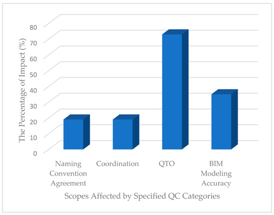
Figure 1.
The percentage contribution of specified scopes affected by the QC categories.
As shown in Figure 2, the proposed framework is a multi-component system designed to enhance the QC of BIM models across various engineering disciplines.
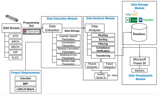
Figure 2.
A comprehensive structure of the developed 3D BIM QC system framework.
This framework comprises four main components: a BIM-based model, a Data Extraction and Analysis Module, a Data Storage Module, and a Data Visualization Module. Engineering teams supply the BIM model for each discipline, forming this framework’s foundation. The primary function of this system is to check the compliance of the design BIM models with the customized QC checklists proposed in this study. To achieve this, a specialized module for each discipline has been developed to automatically extract and analyze the designated QC information from BIM models. In the Data Extraction and Analysis Module, QTO, coordination, naming convention, modeling errors, and identity-related parameter data, as specified in the QC checklist, are extracted from architectural, structural, and MEP BIM models to assess their quality and compliance status automatically. The module, developed in Dynamo, operates by reading, sorting, and filtering the extracted data. It then verifies their compliance against the QC checklist, identifying which elements pass or fail, calculating the quality score for each QC category, and subsequently transferring this information to the Data Storage Module. The Data Storage Module serves as a repository for the processed information. It stores the number of failed and passing elements, the quality score for each QC category, and a list of failed elements, including their unique ID and any critical warning messages that could impact QTO and coordination outputs. While the data can be seamlessly moved to an external database like MySQL, this study utilizes Microsoft Excel for its simplicity and accessibility. The QC Excel files are subsequently uploaded to ProjectWise in the cloud, facilitating smooth integration with the Data Visualization Module in Power BI. A user-friendly dashboard was designed in Power BI to display the QC process outputs effectively and track changes over time. This component provides a clear visual representation of the QC status, facilitating more straightforward interpretation and decision making. The Data Extraction and Analysis Module, developed for each discipline, is distinct due to the different parameter names and filtering techniques required. Figure 3 details the workflow for the structural BIM model’s QC process. This automated workflow includes multiple steps and filtering methods, beginning with the structural BIM model, listing all failing elements with their unique IDs, and calculating the quality score for each QC category. Because the main 3D view of the BIM model might contain elements from other disciplines for coordination purposes, the export 3D view, provided by the BIM modeler to be used in the coordination tools such as Navisworks or BIM 360 Glue, is used for the QC process. In this stage, all BIM categories are selected after inputting the coordination 3D view’s name into the automated module. The module then filters out all unnecessary categories, such as views, lines, STR beam systems, section boxes, and shaft openings, and removes them from the list of extracted categories. This methodology illustrates a comprehensive and detailed approach to BIM QCs, ensuring that each discipline’s specific requirements are met while maintaining a high data accuracy and integrity standard.
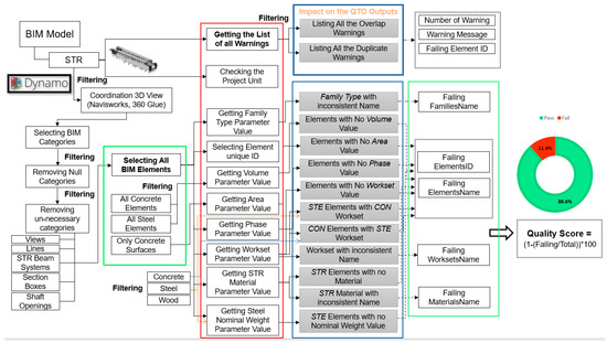
Figure 3.
Overall architecture of the detailed Data Extraction and Analysis Module for the structural BIM model’s QC process.
Quality control in the BIM models involves detailed extraction and analysis of essential parameter values relevant to each category. This systematic approach ensures comprehensive coverage of all necessary parameters for QCs. In the structural BIM model’s QC process, for example, extracting “Family Type” parameter values is essential to verify their consistency with the project’s codification procedures. Similarly, Volume parameter values for steel and concrete components are extracted to confirm that each element has an assigned volume, a critical factor for accurate QTO. For concrete components, Area parameter values are also extracted to ensure that all such elements have an area value, reinforcing the precision of the QTO process. Phase and Workset parameters play a crucial role in the classification of elements. The Phase parameter, in particular, is instrumental in distinguishing new and existing structural components within the 3D model, which is vital for filtering elements during the QTO process. Similarly, the extraction of Phase and Workset parameter values for all 3D elements is conducted to confirm their presence in the model. The Workset parameter values are further analyzed for naming convention consistency. An incorrect Workset name can lead to erroneous QTO results if these parameters are used for classifying steel and concrete quantities. Therefore, the automated workflow identifies concrete and steel components with inappropriate Workset names. Parameter values are extracted for structural materials to ensure that all elements have a material name aligned with the naming convention procedure, which is essential for QTO accuracy. Due to possible modeling errors, the geometry of steel elements might not align with the steel section type, potentially leading to incorrect steel quantity calculations. Consequently, steel elements’ Nominal Weight and Length parameters are considered the most reliable metrics for quantity calculations. The automated workflow developed in this study extracts nominal weight parameter values to identify steel elements lacking these critical data. A comprehensive list of all warnings is automatically extracted and filtered to address critical warning messages in the BIM model. This step identifies warnings directly impacting QTO results, such as overlapping or duplicated elements. Subsequently, the automated system identifies the number of failing and passing elements to calculate the quality score for each part using the following formula:
where:
Failing = total number of failed elements;
Total = total number of elements.
This formula offers a clear and objective metric to assess the quality of each QC category within the BIM model.
Figure 4 and Figure 5 show the Data Extraction and Analysis Module’s detailed workflow for the architectural and MEP BIM models’ QC process, respectively. Each discipline’s workflow includes general sections to be checked and discipline-specific considerations. For architectural BIM models, the module checks additional categories like doors and rooms, ensuring the accuracy of room element geometry and the appropriate codification of door elements.
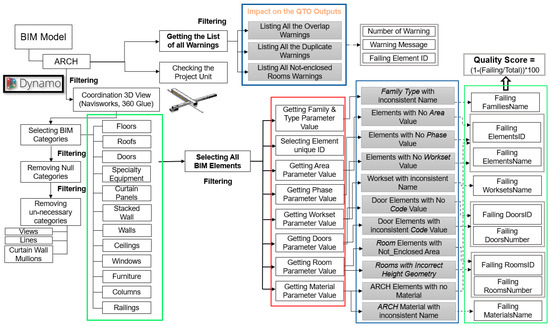
Figure 4.
Overall architecture of the detailed Data Extraction and Analysis Module for the architectural BIM model’s QC process.
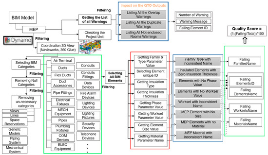
Figure 5.
Overall architecture of the detailed Data Extraction and Analysis Module for the MEP BIM model’s QC process.
Table 3 summarizes the parameters in the Data Extraction and Analysis Module for the MEP BIM model’s QC process. It highlights the specificity of parameter checks according to BIM categories, such as the Insulation Thickness parameter being checked only for certain categories of mechanical and piping models. Conversely, the Material parameter check is limited to the pipe category, demonstrating the tailored approach of the QC process to each discipline.
Table 3.
Listing of parameters for MEP BIM model’s QC process.
4. The System Framework
Based on the project quality control checklist, the developed system automatically evaluates the 3D BIM model data quality. Five Data Extraction and Analysis Modules were developed to assess the quality and consistency of structural, architectural, and MEP BIM data, list the failing elements with their corresponding unique IDs, and present the outcomes and statistics on a user-friendly dashboard developed within the Power BI platform.
4.1. Development of the Case Study BIM Models
A set of engineering architectural, structural, and MEP Revit BIM models from a large construction project in Montreal, Canada, as utilized in the study conducted by Valinejadshoubi et al. in [5], served as the case study to confirm the effectiveness of the developed system. Autodesk Revit was selected for the case study project because of its extensive use in the AEC industry and its user-friendly capabilities that facilitate the creation of buildings’ BIM models. Parameters such as Electrical, Electrical Loads, Electrical Circuiting, System Classification, IFC, Analytical Properties, System Name, System Type, Geometry, Phasing, and Identity Data parameters, including Equipment Codification, are defined in BIM models for different purposes, including operation and maintenance, hand over, QTO, and coordination. The parameters included in the developed automated QC system have been selected according to the customized QC checklist of the case study project. The developed system is adaptable, allowing for the inclusion of additional parameters and points if needed. Figure 6 shows an image of the case study BIM models utilized in this study. As illustrated, the BIM models encompass all detailed components of the building that need to be coordinated, and their data quality assurance is checked.

Figure 6.
A picture of the case study BIM models of different disciplines.
4.2. Data Extraction and Analysis Module
The Data Extraction and Analysis Module comprises five automated Dynamo scripts, featuring a workflow designed to automatically read, categorize, filter, verify, and list the statistics and failed elements, determine the quality score for each QC category, and transfer these scores to the database for recording and visualization purposes. The module was structured for five disciplines: architectural, structural, mechanical, piping, and electrical. The workflow varies by each discipline because the cases and parameters that require verification differ. Figure 7 presents a schematic flowchart depicting the data flow within the developed Data Extraction and Analysis Module.
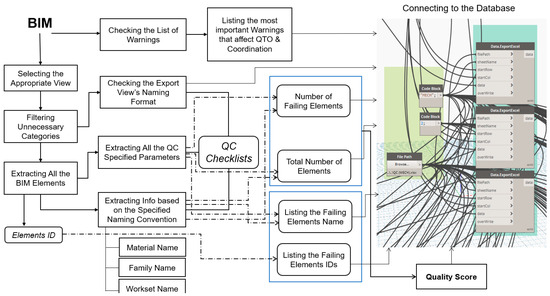
Figure 7.
The dataflow schema of the developed Data Extraction and Analysis Module.
In developing the automated scripts for each discipline, Dynamo leveraged its capabilities in using code blocks. These blocks facilitate the running of compact scripts written in text-based programming languages like C++ and Python, introducing complex functionalities beyond the scope of standard nodes. Thus, the scripts comprise numerous nodes, connections, and code blocks.
4.3. Data Storage Module
This module offers the flexibility of transferring and storing data within a local database, which can subsequently be shared and refreshed on cloud-based document-sharing platforms like ProjectWise or transmitted to cloud-based databases such as Microsoft Access or MySQL. It can also be integrated into BIM collaboration platforms like Speckle that connect with data visualization tools, such as Microsoft Power BI. For this study, a specialized Excel file was created to store all of the information and results produced by the Data Extraction and Analysis Module. This database is segmented into two primary sections: statistics and a list of information. The statistics section includes critical data such as the number of failing elements, the total number of components, and the quality score of each item based on the project’s QC checklist. The second section provides a detailed list of the names and unique IDs of failing elements within the BIM model. This is particularly useful for engineers and BIM modelers to identify and correct these elements in subsequent versions of the model, thereby enhancing the overall quality and accuracy of the BIM models.
4.4. Data Visualization Module
The Data Visualization Module includes a dashboard created within the Power BI platform for displaying the QC results following each update. The developed dashboard comprises six sections, a summary statistics section and five sections for the five disciplines. The summary statistics section contains the total passing and failing elements for each discipline to provide an overall condition of the BIM models’ data quality. Sections for each discipline comprise various components such as “Percentage Pass Organized by Name”, “Percentage Fail Organized by Name”, “Quality Score” for each Category of QC, “Total Number of Fails”, “Total Number of Pass”, “Total Number of Objects”, and a “comparison chart” to compare and track the progress of corrections for every month.
5. Validation Using a Case Study
The modules described above were implemented and validated on a section of a construction project in Montreal, Canada. The design team provided a BIM model for each architectural, structural, mechanical, piping, and electrical discipline. The Data Extraction and Analysis Module, Data Storage Module, and Data Visualization Module were employed to validate the developed system with these models and demonstrate its applicability to construction projects.
Figure 8, Figure 9, Figure 10 and Figure 11 show the algorithms used in automation scripts in the Data Extraction and Analysis Module. Figure 8 shows a part of the automation script to select architectural elements in the BIM model. In this study, after the initial filtering, 7352 architectural elements were selected in the BIM model for the next step in the QC process. Figure 9 shows the algorithm used in the developed architectural QC automation script to check the geometry of room elements in the architectural BIM model. All room elements (59 room objects) were selected in the first step. All related parameters such as “Area”, “Upper Limit”, “Level”, and “Limit Offset” were extracted to check the geometry of room elements as a part of the QC process. This section’s output was to list rooms with geometry-related issues that need to be modified or deleted from the BIM model.
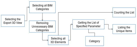
Figure 8.
The algorithm used in the automation script to select and count the total elements in the architectural BIM models.

Figure 9.
The algorithm used in the automation script to check the geometry of room elements in the architectural BIM model.
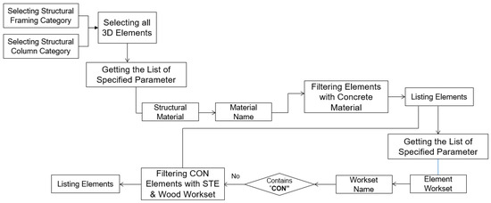
Figure 10.
The algorithm used in the automation script to identify concrete elements within the steel and wood worksets in the structural BIM model.
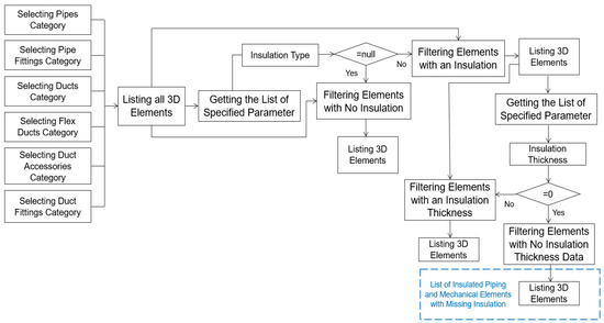
Figure 11.
The algorithm used in the automation script to identify concrete elements within the steel workset in the structural BIM model.
Figure 10 shows the algorithm used in the developed automation script for the structural BIM QC to identify and list structural concrete elements that wrongly have a steel workset. Such misclassifications are not merely nominal but can significantly impact the QTO results, particularly when the workset parameter is employed for classifying quantities. In the case study, this algorithm successfully identified three concrete elements within the BIM model that were mistakenly categorized under the steel workset.
As an essential part of the mechanical BIM model’s QC process, all of the insulated mechanical elements were checked to ensure that they have an insulation thickness value. Figure 11 shows the algorithm utilized in the automation script for the mechanical BIM QC process to identify and list mechanical elements that lack insulation thickness or have it set to zero or null. However, as indicated in the results displayed in Figure 11, all inspected insulated elements in the mechanical BIM model were found to have appropriate insulation thickness values.
Figure 12 shows the summary statistics section for a specified architectural BIM model. As shown, the model comprised 77 distinct family types, of which 1 was identified as non-compliant with the naming convention standards. Regarding material types, the model incorporated 70 different kinds, all adhering to the naming convention criteria. All of the specified architectural categories’ elements, including the wall, roof, floor, and ceiling (846 elements), had material and area parameter names and values in the model. All of the BIM elements (7352 elements) had “Phase” and “Workset” parameter names. Regarding “Workset” parameters, the model included seven distinct names, all in compliance with the naming convention. There were 51 door elements in the model; 40 of them were coded, and 11 lacked codifications. All 40 door elements, which had a codification in the model, passed in terms of interior and exterior coding parameter values. The model also included 59 room elements, out of which 55 passed the room boundary checks. An additional check was conducted on the height of rooms with closed areas to ensure that they contained space between the ceiling and the top floor where MEP equipment might be located. Of the 55 rooms analyzed for height, 25 met the criteria, while 30 did not.
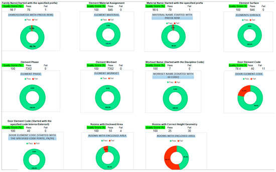
Figure 12.
The result of the summary statistics section for one of the architectural BIM models.
Figure 13 presents a segment of the report for the structural BIM model. This section explicitly lists failing elements, accompanied by their unique IDs. This format was particularly designed to aid engineers in efficiently identifying and modifying problematic elements within the BIM model.
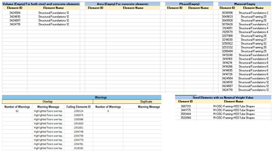
Figure 13.
List of failing elements’ names and their corresponding unique IDs.
According to Figure 13, four structural foundation elements lacked volume parameter values. Additionally, 21 structural elements were identified as not having assigned structural materials, potentially impacting the model’s integrity. Another notable observation was the absence of nominal weight values for four steel elements, underscoring a gap in the model’s data completeness. Furthermore, the model exhibited 62 instances of “Overlap” warning messages, indicating potential geometric conflicts within the model’s structure. It is important to note that columns in the report displaying “No Value”, such as in “Area for Concrete Elements”, “Phase”, and “Duplicate Warnings”, signified the absence of issues within these specific QC categories in the BIM model. This indicated a level of completeness and accuracy in these aspects of the model. The Excel-based QC report files were uploaded to the ProjectWise platform to enhance communication and foster collaboration among project stakeholders. This integration facilitates a connection with the Data Visualization Module. As previously mentioned, the Data Visualization Module comprises six key components: Home_Checklist, STR, ARCH, ELEC, MECH, and PIP. Figure 14 shows the Home_Checklist section of the module for the case study BIM models. This section provides a comprehensive overview of each discipline, listing the total counts of failed and passed BIM elements. The data presented in the figure reveal that the number of elements failing QC checks in the STR, ARCH, ELEC, MECH, and PIP models are 14, 165, 125, 51, 46, and 109, respectively. This breakdown clearly and concisely represents the QC status across different disciplines within the BIM models.

Figure 14.
The Home Checklist section of the Data Visualization Module.
In Figure 15, Figure 16 and Figure 17, the results from the case study’s architectural (ARCH), structural (STR), and electrical (ELEC) BIM models are presented, describing the outcomes based on specific checklists for each discipline. The section consists of different components: Percentage Fail Organized by Name, Category (Name, Quality Score, Sum of Fails, and Sum of Passes), Select Category, and TRACKING FAILS graph. The Percentage Fail Organized by Name component provides a comparative analysis of each QC category’s failure rate relative to the total failure rate. For instance, Figure 15 reveals that within the ARCH checklist, the category “Rooms with Enclosed Area” exhibited the highest failure rate at 58.2%. This was followed by “Door Element Code (started with specified code)” at 22.4%, and “Door Element Code” at 14.9%. Such detailed insights enable engineers to identify which specific cases are lagging in terms of quality based on the number of BIM elements involved. Further, the “Category” table provides additional data, including the quality score and the number of failing and passing elements for each QC category. According to the Category table, categories such as “Element Phase”, “Element Surface”, “Element Workset”, “Family Name”, and “Workset Name” achieved a quality score of 100%, indicating no failures in these areas. Conversely, the “Door Element Code (started with specified code)” category recorded a relatively lower quality score of 50%. Other categories like “Rooms with Enclosed Area”, “Door Element Code”, “Material Name”, and “Element Material” reported quality scores of 53.6%, 75%, 97.6%, and 99.8%, respectively. The “Category” table allows users to focus on specific QC categories and their corresponding results. This feature is particularly useful for engineers requiring a focused analysis of particular aspects of the BIM model. The TRACKING FAILS graph illustrates the month-over-month progression in addressing and correcting failures. This visual representation provides a clear overview of each discipline’s improvements over time.
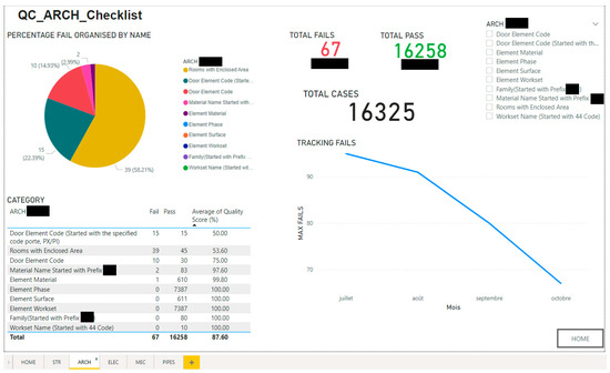
Figure 15.
The ARCH Checklist section of the Data Visualization Module.
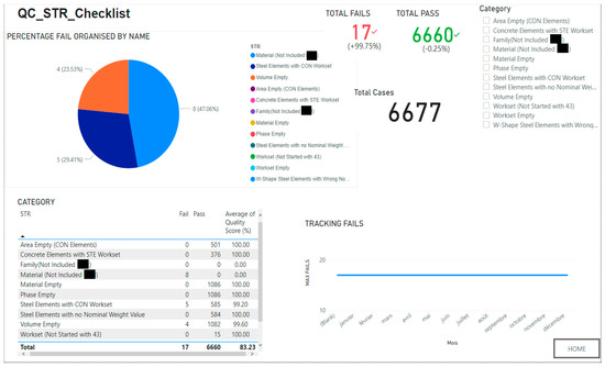
Figure 16.
The STR Checklist section of the Data Visualization Module.
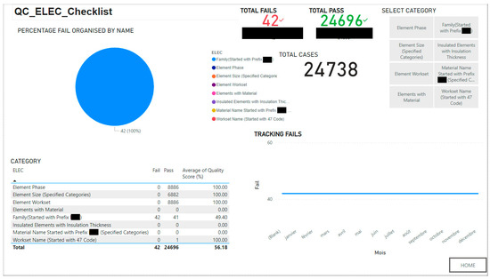
Figure 17.
The ELEC Checklist section of the Data Visualization Module.
Conclusively, the ARCH BIM model’s average quality score, calculated at the end of the Category table, was 87.6%. This score, derived from the aggregate of failing and passing elements across all QC categories, indicated the BIM model’s overall quality in the architectural discipline. As illustrated in the TRACKING FAILS graph, a significant trend was observed in the reduction in failing architectural (ARCH) elements over a four-month period. Initially, in July, the total number of failing ARCH elements stood at 95. This number subsequently decreased to 91 in August, followed by a further reduction to 80 in September, finally reaching 67 in October. This progressive decline in the number of failing elements clearly indicated the effectiveness of the implemented system. It demonstrated its utility in assisting the design teams to gradually identify and rectify issues within their BIM models. The consistent month-over-month improvement proved the system’s role in enhancing the overall quality and accuracy of the BIM models in the project.
In the structural BIM model, as presented in the STR_checklist section results and shown in Figure 16, the “Material Name” category showed the highest failure rate at 47.06%, followed by “Steel Elements with CON Workset” at 29.4%, and “Material Volume” at 23.5%. An analysis of these categories can reveal specific areas where the structural model requires improvements to meet QC standards. As shown at the end of the “Category” table, the average quality score of the structural BIM model was calculated at 83.2% based on the number of failing and passing elements for each QC category. However, the “TRACKING FAILS” graph indicated that the structural design team has yet to address these identified issues in the BIM model.
According to the “ELEC_checklist” section results shown in Figure 17, the only failing category was “Family Name”, with a failure rate of 100% and a total of 42 failure cases detected.
The QC failing categories present an opportunity for corrections aligning with the project’s objectives. For instance, in the case study project, priority was given to the categories influencing the QTO and coordination outputs. Consequently, the architectural BIM model’s failing elements in categories such as “Element Material” (QTO), “Element Surface” (QTO), “Element Phase” (filtering existing elements from the QTO result), “Element Workset” (QTO classification), and “Rooms with Correct Height Geometry” (coordination and handover) were prioritized for modification., Similarly, in the structural BIM model, elements in categories like “Element Material”, “Element Volume”, “Element Surface”, “Concrete Elements with Correct Workset”, “Steel Elements with Correct Workset”, and others related to QTO were given precedence in the modification process.
This QC methodology has been applied to assess 180 design BIM models across various disciplines for the case study project. The effectiveness and precision of the developed system have been validated within the case study, along with the received positive feedback from the design department. The system proved instrumental in identifying inconsistencies, inaccuracies, and errors. The QC reports and visualization files generated have facilitated effective communication between the BIM and design departments, enabling them to address the issues identified and enhance the overall quality of the BIM models, striving toward achieving a 100% AQS.
6. Discussion
The quality and accuracy of information are essential in any construction project, and low-quality BIM can adversely impact crucial tasks such as QTO, coordination, handover, codification, testing, and commissioning. On the other hand, verifying the quality and accuracy of all of the information and parameters included in BIM models is challenging and time-consuming. Therefore, developing an automated QC system for BIM models is critical in any construction project with specified objectives. This paper introduced an innovative, automated BIM-based QC system, specifically for structural, architectural, and MEP disciplines, to ensure the integrity of BIM models concerning QTO, design coordination, and handover processes in accordance with the project’s QC checklists. A significant contribution of this study was developing an integrated system designed to automate and enhance the quality and consistency checks of BIM models across all engineering disciplines. Utilizing a proposed QC checklist, the system addressed the need for a multi-purpose tool that, while initially project-specific, can be adapted for more generic applications with minor modifications, thereby impacting key project outcomes such as QTO, coordination, naming convention, and BIM model accuracy. At the same time, these are the main limitations found in the previous works. The developed system was also applied to the original BIM models, while most previous research used the IFC format to carry out the QC, which causes some issues such as a loss of information, attributes, and properties [38,39,40,41,42,43].
While various BIM tools exist, including Autodesk Revit, Tekla Structures, ArchiCAD, etc., Autodesk Revit was chosen for the developed system because it deals with all engineering branches such as MEP, structure, and architecture. In contrast, other tools, such as Tekla and ArchiCAD, offer BIM for structural and architectural engineering. Conversely, Autodesk Revit offers Dynamo integration, which proves immensely beneficial in automating and expediting information production and management. Additionally, it provides various licensing options.
In text-based programming languages, a programmer is required to write lines of code to develop a program. In contrast, visual-based programming languages enable the programmer to manipulate visual elements to construct a program. Visual coding offers several advantages over text-based coding, including enhanced readability, user-friendly features, and so on. Since the ultimate users of the QC automation code may not be coding experts, a visual programming code like Dynamo is far more user-friendly and comprehensible for them compared to a text-based programming code. Even an engineer with basic programming knowledge can execute or adjust the developed QC automation Dynamo script to suit various project needs. The parameters and scenarios incorporated into the developed BIM QC system were chosen in accordance with the project’s QC checklist and their influence on the accuracy of design coordination and QTO outputs. The list of failing BIM elements’ names and IDs was intended to assist engineers in identifying and correcting issues within BIM models.
The present study explored two methodologies for publishing QC results on the cloud. The selected approach involved utilizing a local data storage tool, such as Microsoft Excel, in conjunction with a cloud-based platform like ProjectWise. This approach was selected for its accessibility and familiarity to those involved in the case study project, ensuring ease of integration and use. In contrast, although technically viable, the alternative method of directly transferring QC results to a cloud-based database like MySQL was not pursued due to constraints related to existing infrastructure and resource availability.
The Power BI platform was chosen for the Data Visualization Module due to its widespread usage and popularity within the AEC industry. Using the cost-effective Power BI Pro platform facilitated enhanced collaboration and distribution of reports and visualizations within the organization. The integration capability of Power BI with various tools and databases, including Microsoft Excel, Microsoft Access, MySQL, and the Speckle platform, underscores its versatility and alignment with BIM model linkage.
However, it is important to note that the scope of the results presented in this paper was limited to Autodesk Revit, Dynamo, ProjectWise, Microsoft Excel, and Microsoft Power BI; the issues analyzed and the frameworks and algorithms defined to overcome them can be adapted to other software solutions.
This study introduced a newly developed QC system to check and evaluate the data quality of BIM models. Figure 18 shows the requirement analysis of the developed system. The process begins with experts, who define the QC rules and requirements aligned with the BEP document. It also includes all of the naming convention procedures. Once approved, the design team initiates the preparation of the requirements of the BIM models during the early design stage, followed by the preliminary QC assessment. If the initial quality target is not met, the design BIM model is returned to the design team for revision. Once the preliminary quality target is attained, the design team proceeds to develop the detailed architectural, structural, and MEP BIM models, including all necessary parameters and information as per the QC rules and requirements established initially. Depending on the project’s scale, the QC can be conducted on the detailed BIM models by either the design team or the BIM department. In this study, the BIM department performed the detailed QC on the engineering BIM models, and QC reports were sent to the design teams to correct their models accordingly. When the BIM models are updated weekly in the cloud, a BIM specialist from the BIM department can perform QC processes through visualization and detailed QC implementation using the developed Data Extraction and Analysis Module. The system automatically generates a comprehensive report detailing identified inconsistencies and missing information. The QC report is then transferred to the Data Visualization Module for the design teams and clients to visualize the QC report data, including Fails Tracking, Fails Percentage, and the AQS number. If a BIM model’s AQS number falls below 100%, the detailed report is forwarded to the design team for the necessary corrections to be made to the BIM model. This iteration continues until all BIM models achieve a 100% AQS number. The process needs close collaboration between the design and BIM departments. An appropriate platform like ProjectWise is essential for effective and fast data sharing between the BIM QC coordinator and design coordinator to send the QC reports after each update to the respective design teams to correct their original BIM models accordingly. A BIM specialist performed the developed QC process on the project’s design BIM models. The process execution time varied up to several minutes for each model, depending on the size of the BIM model.
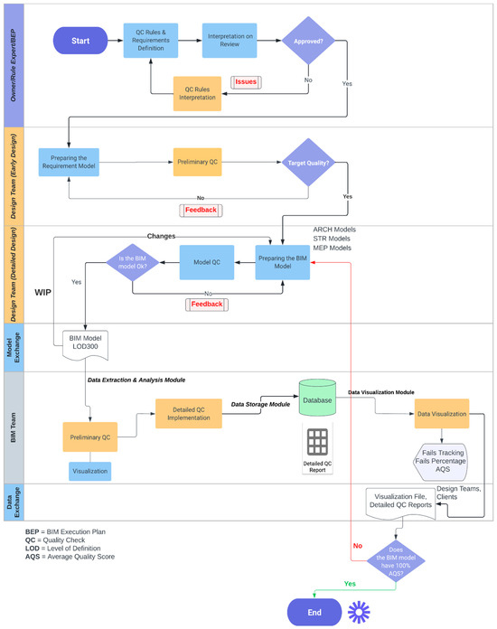
Figure 18.
Requirement analysis of the proposed system development.
However, this study is subject to the following limitations:
- The implementation of the system was limited to Autodesk Revit BIM models, suggesting the possibility of expansion to encompass other types of BIM models from different BIM software.
- The testing and validation of the system were carried out in only a single case study, requiring broader application and testing to fully ascertain its effectiveness across various projects.
- While the system was initially designed for individual disciplinary models, future developments could extend its capabilities to involve all disciplines within a federated BIM model.
- The uniform weight coefficient applied to each check within the system could be refined to reflect the varying impacts of different checks on the project’s cost and timeline.
7. Conclusions
Periodic QCs of BIM models (e.g., weekly or monthly) are essential because BIM models are used to make decisions about buildings’ design, construction, operation, and maintenance. If the models are not of high quality, these decisions will not be based on accurate or complete information. The primary emphasis of this study was on the development of an automated QC system for assessing the quality and consistency of designed BIM models. This system incorporates project-specific QC procedures and checklists, offering applicability to similar construction projects. The system comprises four principal components, including a user-friendly Data Visualization Module and automation scripts designed for various disciplines to detect inconsistencies, errors, and problems in BIM models. The capability of the developed system was explored through a real case study.
The key findings from this study are as follows:
- The automation workflows developed in this study were capable of reading, selecting, sorting, filtering, extracting, and transferring all QC data from STR, ARCH, MECH, PIP, and ELEC BIM models.
- The generated QC reports enabled design teams to rapidly identify and correct failing elements within the BIM models. In the case study, 17, 67, 42, 29, and 55 failing elements were initially detected and listed from the project’s STR, ARCH, ELEC, MECH, and PIP BIM models.
- The Data Visualization Module significantly aided in prioritizing corrections by highlighting QC categories with the highest failure rates, both in terms of the number of failing elements and their quality scores.
- The Data Visualization Module calculated the AQS values of 87.6%, 83.2%, and 56.2% for the case study’s architectural, structural, and electrical BIM models, providing a comprehensive quality overview and alerting engineers and QC teams to potential issues.
- The application of the QC system in a case study demonstrated a 30% reduction in failing elements for the architectural design team over four months, indicating the system’s efficiency.
- The system proved beneficial in identifying missing data or information within the BIM models. For example, in the case study STR BIM model, 21 structural elements did not have an assigned structural material parameter value, and 4 steel elements were identified as not having an assigned nominal weight parameter value.
- Additionally, the Data Visualization Module facilitated the design teams’ tracking of correction progress in the BIM models, which provided a clear overview of each discipline’s improvements over time.
This study underscores the importance of periodic QCs in BIM models, which are vital for informed decision making in building design, construction, operation, and maintenance. By enabling timely identification and correction of failing elements, the developed system can prevent problems leading to increased costs and delays, thereby enhancing the overall efficiency of BIM-based project management.
Author Contributions
Conceptualization, M.V.; Methodology, M.V.; Software, M.V.; Validation, M.V.; Formal analysis, M.V.; Investigation, M.V.; Resources, M.V.; Data curation, M.V.; Writing—original draft, M.V.; Writing—review & editing, M.V., I.I., F.V. and A.B.; Visualization, A.S.; Supervision, O.M. All authors have read and agreed to the published version of the manuscript.
Funding
This research received no external funding.
Data Availability Statement
The data presented in this study are available on request from the corresponding author. The data are not publicly available due to confidentiality and privacy.
Acknowledgments
The authors acknowledge Oscar Mannarella, the senior VDC coordinator at Pomerleau Inc., for his assistance in the preliminary development and testing of the Data Visualization Module.
Conflicts of Interest
Authors Mojtaba Valinejadshoubi, Fernando Valdivieso and Azin Shakibabarough were employed by the company Pomerleau Inc. The remaining authors declare that the research was conducted in the absence of any commercial or financial relationships that could be construed as a potential conflict of interest.
References
- Nassar, K. The Effect of Building Information Modelling on the Accuracy of Estimates. In Proceedings of the 46th Annual Conference, Wentworth Institute of Technology, Boston, MA, USA, 7–10 April 2010. [Google Scholar]
- Singh, I. BIM Adoption and Implementation Around the World: Initiatives by Major Nations. Geospatial World. 2017. Available online: https://www.geospatialworld.net/blogs/bimadoption-around-the-world/ (accessed on 4 May 2017).
- Choi, J.; Kim, I. An approach to share architectural drawing information and document information for automated code checking system. Tsinghua Sci. Technol. 2008, 13, 171–178. [Google Scholar] [CrossRef]
- Choi, J.; Choi, J.; Kim, I. Development of BIM-based Evacuation Regulation Checking System for High-rise and Complex Buildings. J. Autom. Constr. 2014, 46, 38–49. [Google Scholar] [CrossRef]
- Valinejadshoubi, M.; Moselhi, O.; Iordanova, I.; Valdivieso, F.; Bagchi, A. Automated system for high-accuracy quantity takeoff using BIM. Autom. Constr. 2024, 157, 105155. [Google Scholar] [CrossRef]
- Valinejadshoubi, M.; Moselhi, O.; Bagchi, A. Integrating BIM into sensor-based facilities management operations. J. Facil. Manag. 2021, 20, 385–400. [Google Scholar] [CrossRef]
- Valinejadshoubi, M.; Bagchi, A.; Moselhi, O. Development of a BIM-Based Data Management System for Structural Health Monitoring with Application to Modular Buildings: Case Study. J. Comput. Civ. Eng. 2019, 33, 05019003. [Google Scholar] [CrossRef]
- Valinjadshoubi, M.; Bagchi, A.; Moselhi, O. Managing structural health monitoring data using building information modeling. In Proceedings of the 2nd World Congress and Exhibition on Construction and Steel Structure, Las Vegas, NV, USA, 22–24 September 2016. [Google Scholar] [CrossRef]
- Valinejadshoubi, M.; Bagchi, A.; Moselhi, O.; Shakibaborough, A. Investigation on the potential of building information modeling in structural health monitoring of buildings. In Proceedings of the CSCE Annual Conference, Fredericton, NB, Canada, 13–16 June 2018. [Google Scholar]
- Peng, J.; Liu, X. Automated code compliance checking research based on BIM and knowledge graph. Sci. Rep. 2023, 13, 7065. [Google Scholar] [CrossRef] [PubMed]
- Amor, R.; Dimyadi, J. The promise of automated compliance checking. Dev. Built Environ. 2021, 5, 100039. [Google Scholar] [CrossRef]
- Aydin, M. The Data Representations of a Building Project: BIM Model, and IFC or IFCXML Data Standard. In Sand in Construction; IntechOpen: London, UK, 2022; ISBN 978-1-80355-586-7. [Google Scholar] [CrossRef]
- Shih, S.-Y.; Sher, W.; Giggins, H. Assessment of the Building Code of Australia to Inform the Development of BIM-enabled Code-checking Systems. In Proceedings of the 19th World Building Congress: Construction and Society, Brisbane, Australia, 5–9 May 2013. [Google Scholar]
- Doukari, O.; Greenwood, D.; Rogage, K.; Kassem, M. Object-Centred Automated Compliance Checking: A Novel, Bottom-Up Approach. J. Inf. Technol. Constr. 2021, 27, 335–362. [Google Scholar] [CrossRef]
- Pinheiro, S.; Corry, E.; O’Donnell, J. Requirements for a BIM-Based Lifecycle Performance Evaluation Framework to Enable Optimum Building Operation. In Proceedings of the 32nd CIB W78 Conference 2015, Eindhoven, The Netherlands, 27–29 October 2015; CIB: Rotterdam, The Netherlands, 2015. [Google Scholar]
- Eastman, C.; Lee, J.; Jeong, Y.; Lee, J. Automatic rule-based checking of building designs. J. Autom. Constr. 2009, 18, 1011–1033. [Google Scholar] [CrossRef]
- Sijie, Z.; Kristiina, S.; Markku, K.; Ilkka, R.; Eastman, C.; Jochen, T. BIM-based fall hazard identification and prevention in construction safety planning. Saf. Sci. 2015, 72, 31–45. [Google Scholar]
- Kubba, S. Handbook of Green Building Design and Construction; Butterworth-Heinemann: Oxford, UK, 2012. [Google Scholar] [CrossRef]
- Choi, J.; Kim, I.; Shin, J. Development of Automated BIM Data Quality Pre-Check (BDQPC) System in Architectural Design Phase. Int. J. Eng. Technol. 2019, 8, 492–499. [Google Scholar]
- Aydin, M.; Taman, H. An overview of building information modelling (bim) based building code compliance checking literature. J. Des.+Theory 2018, 14, 59–77. [Google Scholar] [CrossRef]
- Aydın, M.; Yaman, H. A literature review of automated code compliance checking concept. J. Des.+Theory 2020, 16, 79–97. [Google Scholar] [CrossRef]
- Aydın, M. Building Information Modeling Based Automated Building Regulation Compliance Checking Asp.net Web Software. Intell. Autom. Soft Comput. 2021, 28, 11–25. [Google Scholar] [CrossRef]
- Choi, J.; Kim, I. A Methodology of Building Code Checking System for Building Permission based on openBIM. In Proceedings of the 34th ISARC, Taipei, Taiwan, 28 June–1 July 2017; pp. 945–950. [Google Scholar]
- Nguyen, T.H.; Kim, J.J. Building code compliance checking using BIM technology. In Proceedings of the 2011 Winter Simulation Conference (WSC), Phoenix, AZ, USA, 11–14 December 2011. [Google Scholar] [CrossRef]
- Villaschi, F.S.; Carvalho, J.P.; Braganca, L. BIM-Based Method for Building Code Compliance. J. Appl. Syst. Innov. 2022, 5, 64. [Google Scholar] [CrossRef]
- Getuli, V.; Ventura, S.M.; Capone, P.; Ciribini, A.L.C. BIM-based code checking for construction health and safety. In Proceedings of the Creative Construction Conference 2017, Primosten, Croatia, 19–22 June 2017; Volume 196, pp. 454–461. [Google Scholar]
- Borrmann, A.; König, M.; Koch, C.; Beetz, J. (Eds.) . Building Information Modeling—Technology Foundations and Industry Practice; Springer: Berlin/Heidelberg, Germany, 2018. [Google Scholar] [CrossRef]
- Yogana, E.; Latief, Y. Development of system information of building code checking in planning and permitting phase to improve building code compliance based on work breakdown structure (WBS) using building information modeling (BIM). J. Phys. Conf. Ser. 2021, 1858, 012091. [Google Scholar] [CrossRef]
- Altintas, Y.D.; Ilal, M.E. Integrating building and context information for automated zoning code checking: A review. J. Inf. Technol. Constr. (ITcon) 2022, 27, 548–570. [Google Scholar] [CrossRef]
- MLTM (Ministry of Land Transport and Maritime Affairs). 2010 BIM Guide of Ministry of Land Transport and Maritime Affairs; MLTM (Ministry of Land Transport and Maritime Affairs): Sejong, Republic of Korea, 2010.
- Noardo, F.; Ohori, K.A.; Krijnen, T.; Stoter, J. An Inspection of IFC Models from Practice. Appl. Sci. 2021, 11, 2232. [Google Scholar] [CrossRef]
- Hamledari, H.; Rezazadeh Azar, E.; McCabe, B. IFC-Based Development of As-Built and As-Is BIMs Using Construction and Facility Inspection Data: Site-to-BIM Data Transfer Automation. J. Comput. Civ. Eng. 2018, 32, 04017075. [Google Scholar] [CrossRef]
- Choi, J.; Lee, S.; Kim, I. Development of Quality Control Requirements for Improving the Quality of Architectural Design Based on BIM. Appl. Sci. 2020, 10, 7074. [Google Scholar] [CrossRef]
- Donato, V.; Turco, M.L.; Bocconcino, M.M. BIM-QA/QC in the architectural design process. Arch. Eng. Des. Manag. 2017, 14, 239–254. [Google Scholar] [CrossRef]
- Xu, Z.; Huang, T.; Li, B.; Li, H.; Li, Q. Developing an IFC-Based Database for Construction Quality Evaluation. Adv. Civ. Eng. 2018, 2018, 3946051. [Google Scholar] [CrossRef]
- Temel, B.A.; Başağa, H.B. Investigation of IFC file format for BIM based automated code compliance checking. J. Constr. Eng. Manag. Innov. 2020, 3, 113–130. [Google Scholar] [CrossRef]
- Pazlar, T.; Turk, Z. Interoperability in practice: Geometric data exchange using the IFC standard. Electron. J. Inf. Technol. Constr. 2018, 13, 362–380. [Google Scholar]
- Jeong, Y.S.; Eastman, C.M.; Sacks, R.; Kaner, I. Benchmark tests for BIM data exchanges of precast concrete. J. Autom. Constr. 2009, 18, 469–484. [Google Scholar] [CrossRef]
- Nizam, R.S.; Zhang, C. Current State of Information Exchange between the two most popular BIM software: Revit and Tekla. In Proceedings of the 1st International Conference on Sustainable Building and Structures, Sustainable Building and Structures, Suzhou, China, 29 October–1 November 2015. [Google Scholar]
- Sibenik, G. Building information modelling based interdisciplinary data exchange: A case study. In Proceedings of the 1st International UK BIM Academic Forum Conference, Glasgow, UK, 13–15 September 2016; pp. 379–390. [Google Scholar]
- Ramaji, I.J.; Memari, A.M. Interpreted Information Exchange: Systematic Approach for BIM to Engineering Analysis Information Transformations. J. Comput. Civ. Eng. 2016, 30, 04016028. [Google Scholar] [CrossRef]
- Lai, H.; Deng, X. Interoperability analysis of IFC-based data exchange between heterogeneous BIM software. J. Civ. Eng. Manag. 2018, 24, 537–555. [Google Scholar] [CrossRef]
- Marcolin, G. Structural Information Modeling Proposta di Sviluppo di Standard Informative Open BIM per L’integrazione di Analisi Strutturali. Master’s Thesis, University of Padua, Padua, Italy, 2017. Available online: http://tesi.cab.unipd.it/56332 (accessed on 17 September 2021). (In Italian).
Disclaimer/Publisher’s Note: The statements, opinions and data contained in all publications are solely those of the individual author(s) and contributor(s) and not of MDPI and/or the editor(s). MDPI and/or the editor(s) disclaim responsibility for any injury to people or property resulting from any ideas, methods, instructions or products referred to in the content. |
© 2024 by the authors. Licensee MDPI, Basel, Switzerland. This article is an open access article distributed under the terms and conditions of the Creative Commons Attribution (CC BY) license (https://creativecommons.org/licenses/by/4.0/).