Abstract
Recent literature indicates that the diffractive sail concept is an interesting alternative to the more conventional reflective solar sail, which converts solar radiation pressure into a (deep space) thrust using a thin, lightweight highly reflective membrane, usually metalized. In particular, a diffractive sail, which uses a metamaterial-based membrane to diffract incoming solar rays, is able to generate a steerable thrust vector even when the sail nominal plane is perpendicular to the Sun–spacecraft line. This paper analyzes the optimal transfer performance of a diffractive-sail-based spacecraft in a challenging heliocentric scenario that is consistent with the proposed Solar Polar Imager mission concept. In this case, the spacecraft must reach a near-circular (heliocentric) orbit with a high orbital inclination with respect to the Ecliptic in order to observe and monitor the Sun’s polar regions. Such a specific heliocentric scenario, because of the high velocity change it requires, is a mission application particularly suited for a propellantless propulsion system such as the classical solar sail. However, as shown in this work, the same transfer can be accomplished using a diffractive sail as the primary propulsion system. The main contribution of this paper is the analysis of the spacecraft transfer trajectory using a near-optimal strategy by dividing the entire flight into an approach phase to a circular orbit of the same radius as the desired final orbit but with a smaller inclination, and a subsequent cranking phase until the desired (orbital) inclination is reached. The numerical simulations show that the proposed strategy is sufficiently simple to implement and can provide solutions that differ by only a few percentage points from the optimal results obtainable with a classical indirect approach.
1. Introduction
Observing the Sun’s polar regions is a goal of great scientific interest and a necessary step towards understanding some fundamental physical phenomena and answering not yet clear questions concerning, for example, the creation of the solar wind, the release and evolution of coronal mass ejections, and the creation and control of the heliosphere. Another objective of great importance is to obtain detailed magnetic maps of the polar regions to improve understanding of the Sun’s magnetic dynamo and to obtain new information on the fast solar wind originating from polar coronal holes [1,2].
Unfortunately, the Sun’s polar regions are not visible from Earth or from spacecraft moving on orbits in the plane of the Ecliptic or at a small inclination to it. For this reason, a typical requirement of missions designed to obtain images of the Sun’s polar regions is to achieve a circular orbit of a sufficiently small radius, typically less than or equal to , and an inclination of at least , so as to ensure a sufficiently long residence time at high solar latitudes during which observations of the poles can be made. Reaching such high inclinations relative to the Ecliptic, however, requires extremely large s, which are impossible to achieve with today’s launch vehicles. A mission based on the use of chemical thrusters therefore needs the aid of a planetary gravity assist in order to achieve the high orbital inclinations required [3]. This, for example, was the choice made in the case of the ESA-NASA Ulysses spacecraft, which, launched in 1990, achieved an inclination of with respect to the Ecliptic via a Jupiter gravity-assist maneuver. The final heliocentric orbit, however, was not able to get very close to the Sun, having a perihelion located at a distance of [4].
February 2020 saw the launch of the Solar Orbiter, a mission involving an international collaboration between ESA and NASA to explore the Sun’s polar regions and the heliosphere from close range. The probe uses chemical propulsion and exploits seven Venus gravity-assist maneuvers to decrease the perihelion distance to and increase the orbital inclination [5]. The final orbit has a maximum heliolatitude of in the nominal mission and in the extended mission, which, taking into account the axial tilt of the Sun polar axis, corresponds to an inclination of approximately on the Ecliptic.
Due to the complications and long mission times caused by trajectories with multiple gravity-assist maneuvers, possible alternatives to the use of chemical propulsion have been proposed, as, for example, electric thrusters [6] or more advanced propellantless propulsion systems such as solar sails [7,8]. In fact, solar sails were suggested as a means of propulsion in the technical feasibility study for a Solar Polar mission conducted by JPL in 1996 [9] and have subsequently been considered in various mission analyses and optimal trajectory analyses [10,11,12]. In a recent conceptual study of the Solar Polar Imager mission, concluded by NASA’s Advanced Concepts Office, a square solar reflective sail with a side of was designed to achieve a circular orbit around the Sun of radius and an inclination of [13]. The estimated total mission time was , including of observations and in situ measurements.
Optical diffraction is another physical phenomenon that allows momentum transfer between photons from the Sun and the surface of a solar sail. This phenomenon is the basis of the concept of diffractive sail, recently introduced by Swartzlander [14,15,16,17]. A distinctive feature of a diffractive sail, which uses a metamaterial-based membrane to diffract the incoming solar rays, is its ability to generate an steerable thrust vector even in a Sun-facing condition, that is, when the nominal plane of the sail is normal to the Sun–spacecraft line. This characteristic distinguishes it significantly from a more conventional reflective solar sail, which, on the other hand, in the same Sun-facing orientation can only generate a radial thrust. Therefore, the plane of the reflective sail must be tilted by some angle from the normal direction to generate a transverse component of the thrust. As a result of this, attitude control of a diffractive sail is much simpler than for a reflective sail and in principle could also be implemented passively by designing the sail with a slightly conical shape [18]. In general, therefore, a nearly Sun-facing diffractive sail may prove to be a very promising propulsion device and relatively simple to use in terms of guidance, navigation, and control mechanisms [19,20].
The diffractive sail surface consists of a polarization grating whose period, if appropriately chosen, can convert a relevant fraction (greater than ) of the solar black body spectrum into spacecraft momentum [15]. Specifically, a Sun-facing ideal diffractive sail is capable of generating a thrust inclined by an angle of with respect to the radial direction and thus generating a component in the plane of the sail of the modulus equal to the radial one. The high value of the transverse thrust component of the diffractive sail underlies its potential advantages over a reflective sail. More precisely, comparing a diffractive and a reflective sail on the same reference mission for the same area-to-mass ratio, the diffractive sail allows the target to be reached in a shorter flight time or, for the same mission time, the diffractive sail allows the use of a smaller area-to-mass ratio than the reflective sail [21]. Recently, the performance of this type of propellantless systems has been studied in a number of mission scenarios [22], including orbit raising [19], interplanetary transfers [23], and the generation of heliocentric non-Keplerian orbits [24].
The aim of this work is to assess the performance of a diffractive sail in a mission to observe the Sun’s polar regions, and thus to evaluate the ability of this means of propulsion to generate orbits with a high inclination with respect to the Ecliptic. Since the calculation of the optimal trajectories for missions of this type is a non-trivial problem to solve, the fundamental contribution of this work is to provide a simplified solution methodology, consisting in the use of a two-phase strategy, which consists of dividing the calculation of the minimum-time trajectory towards the target orbit into a phase of approach to the Sun and a phase of rotation of the orbital plane. This strategy proves to be near-optimal in the sense that the mission times determined in this way deviate by only a few percentage points from an overall optimal trajectory.
2. Mission Description and Models Used
The mission scenario considered is the same as that proposed by Dubill and Swartzlander [21]. It is a mission using a 6U CubeSat [25] with a mass of , similar to that used by the NASA Near-Earth Asteroid Scout [26], but in our study the CubeSat is propelled by a Sun-facing diffractive (solar) sail. The mission objective is to place the satellite in a target circular orbit around the Sun with a radius and an inclination with respect to the Ecliptic. Thrust control is achieved by rotating the sail plane by an angle around the radial direction. This rotation angle, called the clock angle, is the only control variable of the trajectory and can be generated by means of a suitable reaction wheel, as discussed in Ref. [21]. As the clock angle varies, the thrust vector describes a cone with a half angle of with respect to the Sun–spacecraft direction. Figure 1 shows the diffractive sail in its motion along the osculating orbit and highlights the radial–tangential–normal reference frame with unit vectors , , and used to write the components of the propulsive acceleration vector.
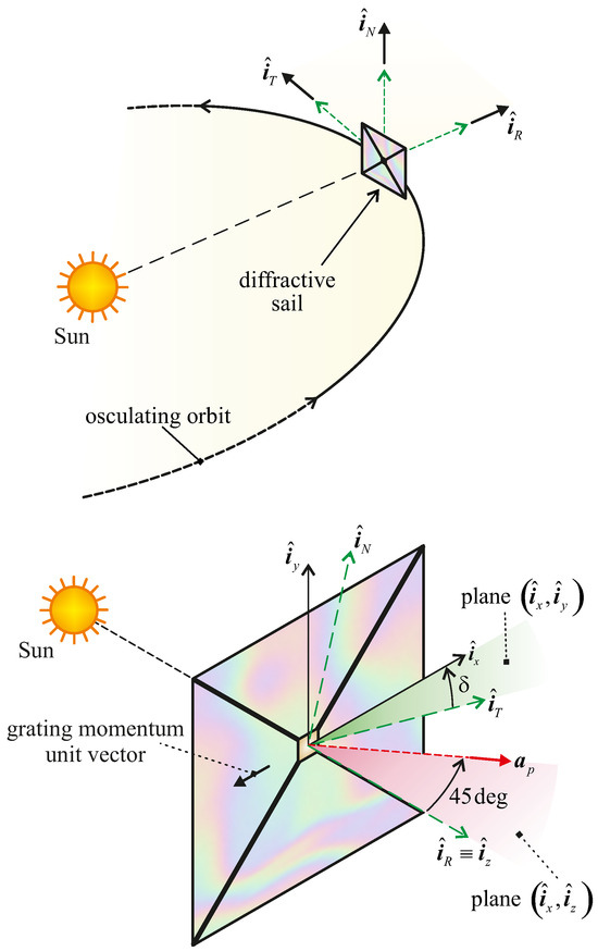
Figure 1.
Definition of clock angle , radial–tangential–normal reference frame, and direction of propulsive acceleration .
Figure 1 also shows that , measured in the nominal plane of the sail, is the angle between and , where the latter is in the opposite direction of the (diffractive film) grating momentum vector. The diffractive sail thrust model used in the simulations is that described in Ref. [19] in which the propulsive acceleration is a function of the characteristic acceleration (defined as the maximum value of at the reference distance ), the distance r, and the clock angle as
Note that, unlike a classical reflective sail, the thrust generated by a diffractive sail cannot be zeroed out, and thus the spacecraft trajectory cannot contain any coasting arc. The mission studied in the simulations consists of a heliocentric transfer trajectory between the orbit of the Earth and the circular orbit of arrival of a fixed radius and inclination. The spacecraft is subject only to the thrust generated by the diffractive sail and the Sun’s gravitational pull, while all other sources of perturbation are neglected. The objective of this work is to determine the minimum-time trajectory that allows the spacecraft to be transferred to the target orbit starting from the Earth with zero hyperbolic excess velocity relative to the planet.
In this study, the heliocentric orbit of the Earth is considered in its actual shape, that is, an ellipse with semimajor axis and eccentricity . Previous studies concerning minimum-time trajectories to achieve a highly inclined orbit around the Sun with reflective sails [11,27] have shown that depending on the value of the radius and inclination of the final orbit, as well as the value of the characteristic acceleration of the solar sail spacecraft, the optimal trajectory may steadily decrease the distance from the Sun until is reached or, more frequently, may initially decrease the distance to values of , so as to take advantage of the increased solar radiation pressure to facilitate the change in orbital inclination, and then increase the distance from the Sun again until the target orbit is reached. In the latter case, the distance from the Sun must be constrained not to fall below a minimum value, which typically depends on the maximum tolerable temperature of the sail film [28].
The analysis of the behaviour of optimal trajectories of reflective sails inspired the two-phase strategy used in the study of diffractive sails’ transfers, which will be illustrated in the following section. The model used in the description of spacecraft dynamics uses modified equinoctial orbital elements, whose time derivatives as a function of are given in Equations (8)–(20) of Ref. [19]. The minimum-time trajectories for transferring the spacecraft to the target orbit have been calculated by solving an optimal orbit-to-orbit transfer problem using the control law described in Ref. [19], in which the only control variable is the clock angle. More precisely, the angular position of the spacecraft on the initial and final orbit is left free to vary (ephemeris-free case), and the exact values of the spacecraft true anomaly at the beginning and end of the transfer are considered as the outputs of the optimal problem solution.
3. Transfer Strategy
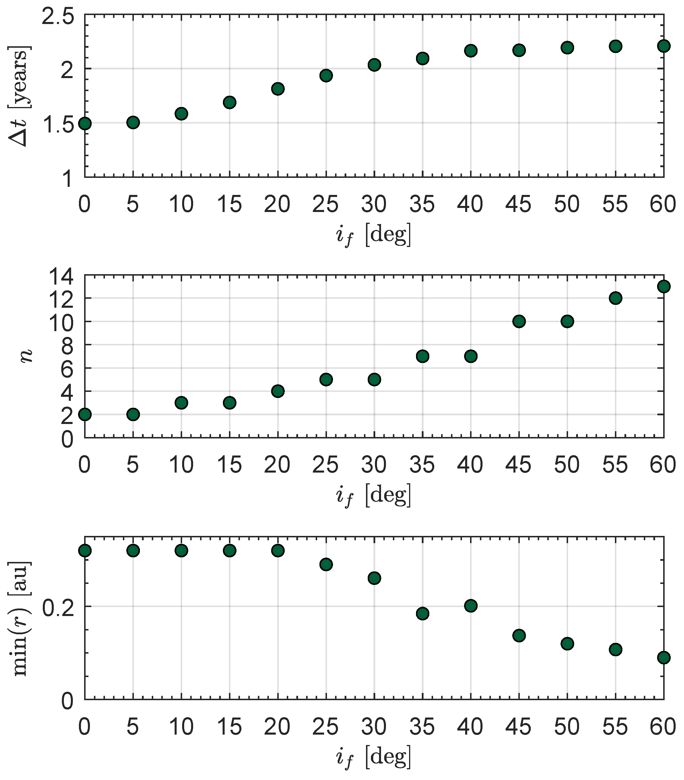
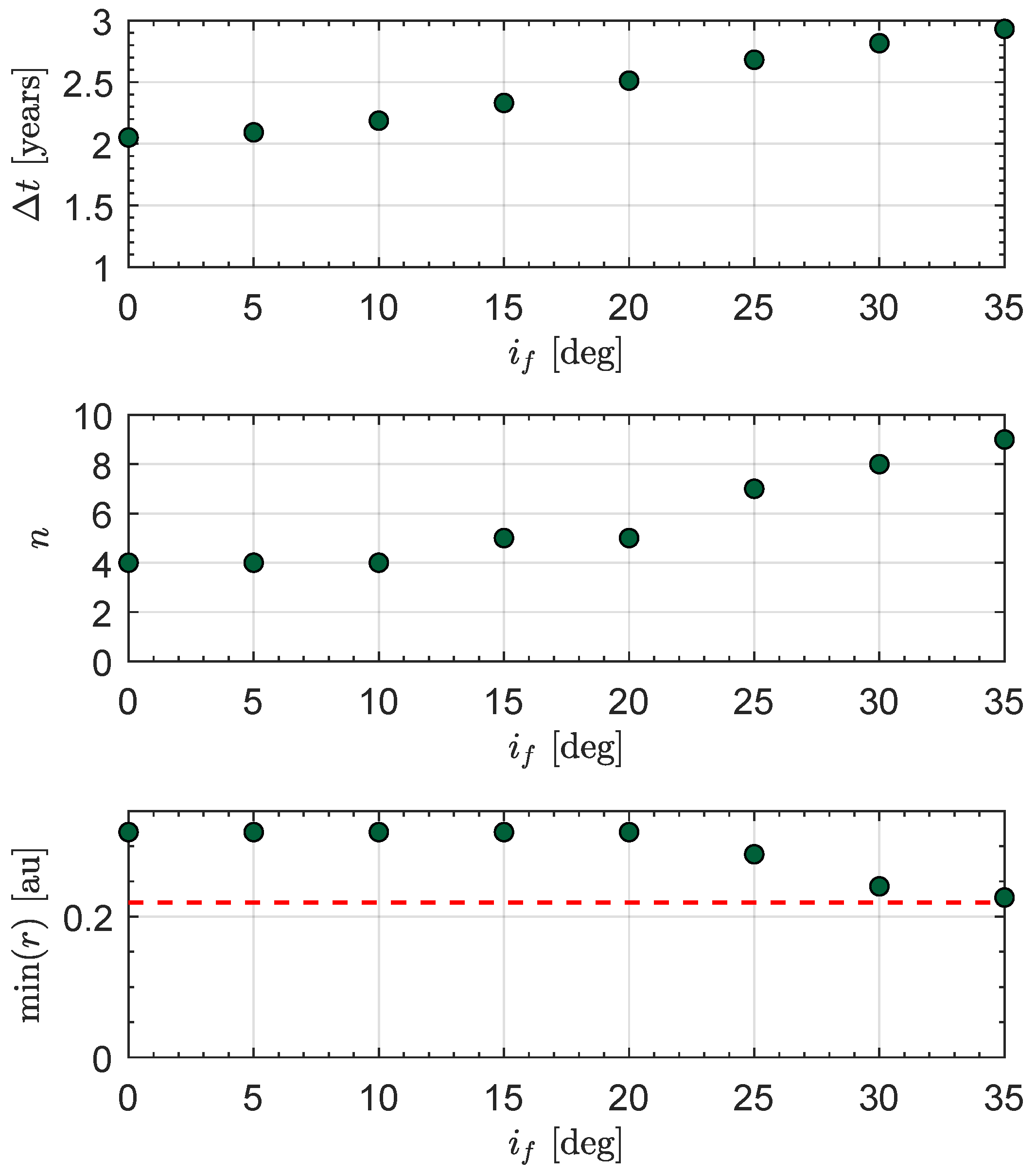
As mentioned in the previous section, it is not possible to determine a priori whether or not the minimum-time trajectory requires a close pass to the Sun in order to reduce the time necessary to increase the orbital inclination and reach the plane of the target orbit. To better analyze this problem, unconstrained optimal transfers to the target orbit were preliminarily calculated, without taking into account the minimum distance from the Sun reached during the transfer. These transfers were obtained by imposing to reach in the minimum time a circular orbit of a radius equal to that of the target orbit (i.e., ), but varying the final orbit inclination in the interval with a step of . Simulations were carried out using a characteristic acceleration , which is compatible with the performance of the reflective sail used for the Solar Polar Imager mission study [29].
The results can be seen in Figure 2, where the optimal transfer times , the total number of revolutions around the Sun n, and the minimum distance from the Sun reached during the transfer are illustrated. The figure shows that up to an inclination of about , the trajectory tends to the target orbit without the minimum distance dropping below , while for larger inclinations, the minimum-time trajectory would tend to approach the Sun up to distances less than and then rise to the final desired value. Assuming that the minimum distance from the Sun compatible with the maximum thermal load supportable by the sail is , which corresponds to the perihelion distance of Mercury from the Sun, it is clear that unconstrained transfers with inclinations greater than about are not feasible.
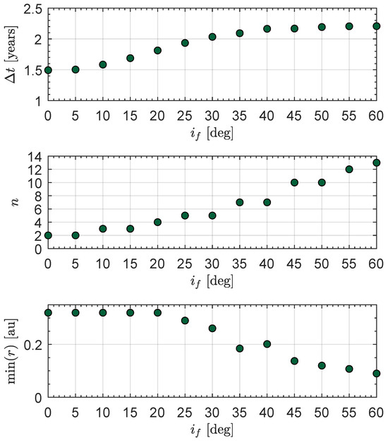
Figure 2.
Simulations of optimal trajectories with to a circular heliocentric orbit of radius for different values of final orbital inclination.
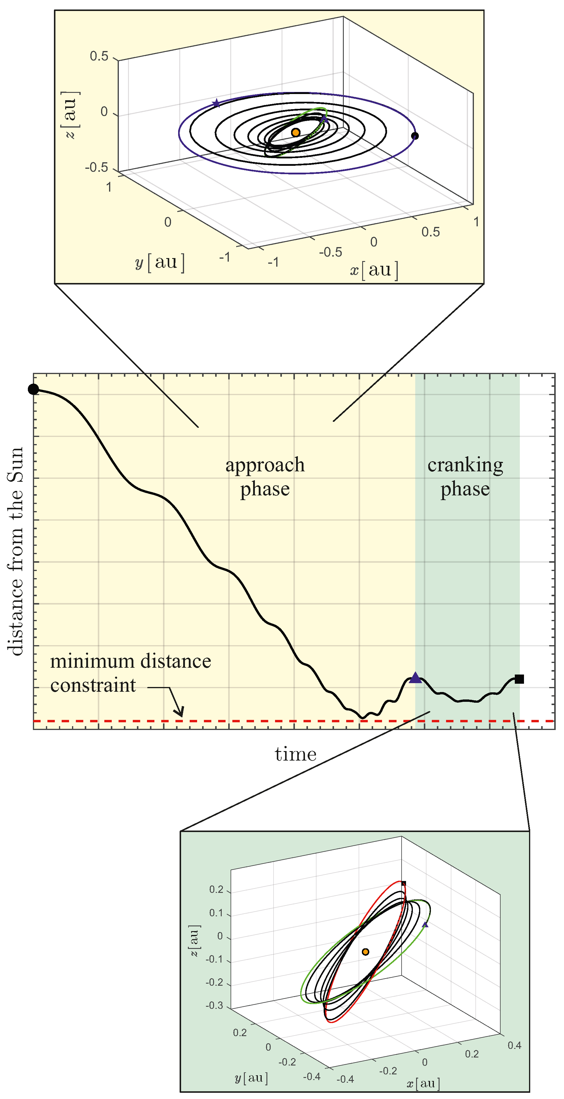
Since the computation of minimum-time trajectories with a constraint on the minimum distance from the Sun usually presents considerable numerical convergence difficulties [27], it was decided to study near-optimal trajectories, using a two-step strategy. In more detail, having fixed the value of , with the help of the results in Figure 2 it is possible to determine the maximum inclination, denoted by , achievable with an unconstrained optimal transfer such that the satellite is taken to the final distance without violating the constraint on . Clearly, it follows from the definition that . The near-optimal trajectory consists of a first phase (referred to as approach phase) in which the spacecraft reaches a circular orbit with radius and inclination using a minimum-time trajectory. The second phase consists of an optimal cranking trajectory, i.e., a minimum-time trajectory in which the initial and final distances coincide and the orbital plane is rotated until the final orbital inclination is obtained. At the end of the second phase, the spacecraft has thus reached the circular orbit of radius and inclination . The strategy adopted is qualitatively illustrated in Figure 3 in which the blue triangle represents the instant at which the first phase ends and the second begins.
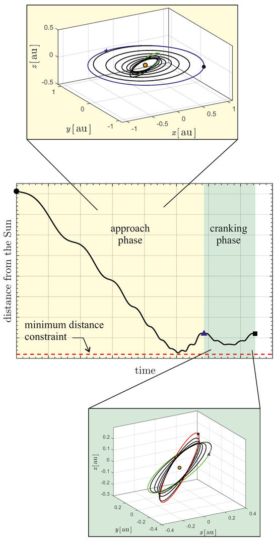
Figure 3.
Illustration of the two-phase strategy with the approach phase and the cranking phase. The green and red solid line represent the orbit at the end of the first and final phase, respectively.
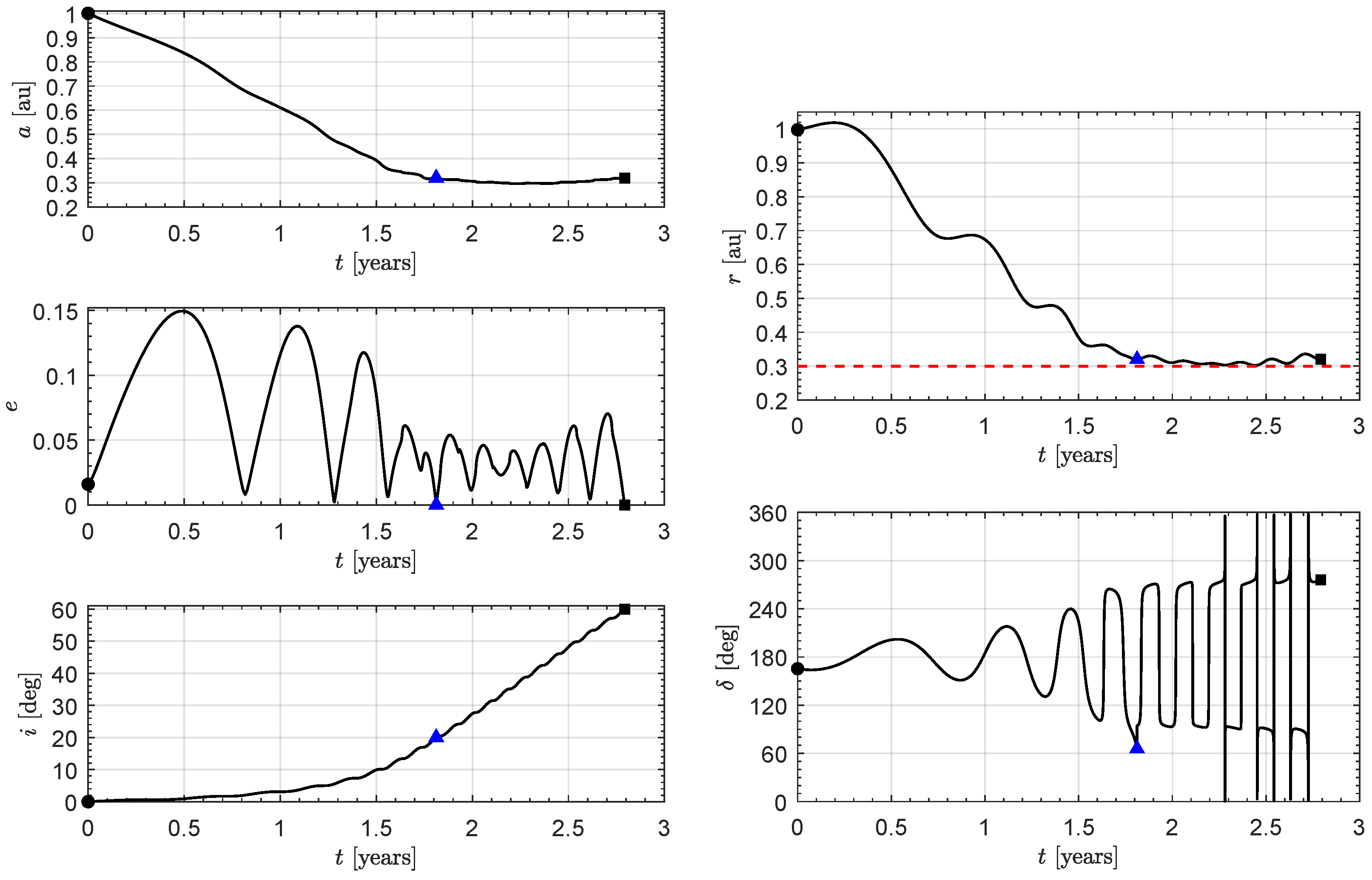
Using this strategy in the present case, the first phase consists of reaching a circular orbit of radius and inclination , while the cranking phase consists of the minimum-time trajectory that transfers the spacecraft to the orbit with inclination and the radius still equal to . The results of the simulations are summarized in Figure 4, which shows the time variation of the semimajor axis, eccentricity, inclination, distance from the Sun, and sail clock angle. Note that the eccentricity at the end of the first phase is zero, in accordance with the fact that the osculating orbit is circular. The first phase lasts , and the second , for a total of of transfer time.
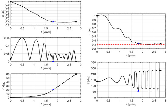
Figure 4.
Time variation of orbital parameters and control variable in a near-optimal transfer to a circular heliocentric orbit of radius and inclination using the two-phase strategy (). Black circle → start; black square → arrival; blue triangle → first phase end; dashed red line → minimum solar distance.
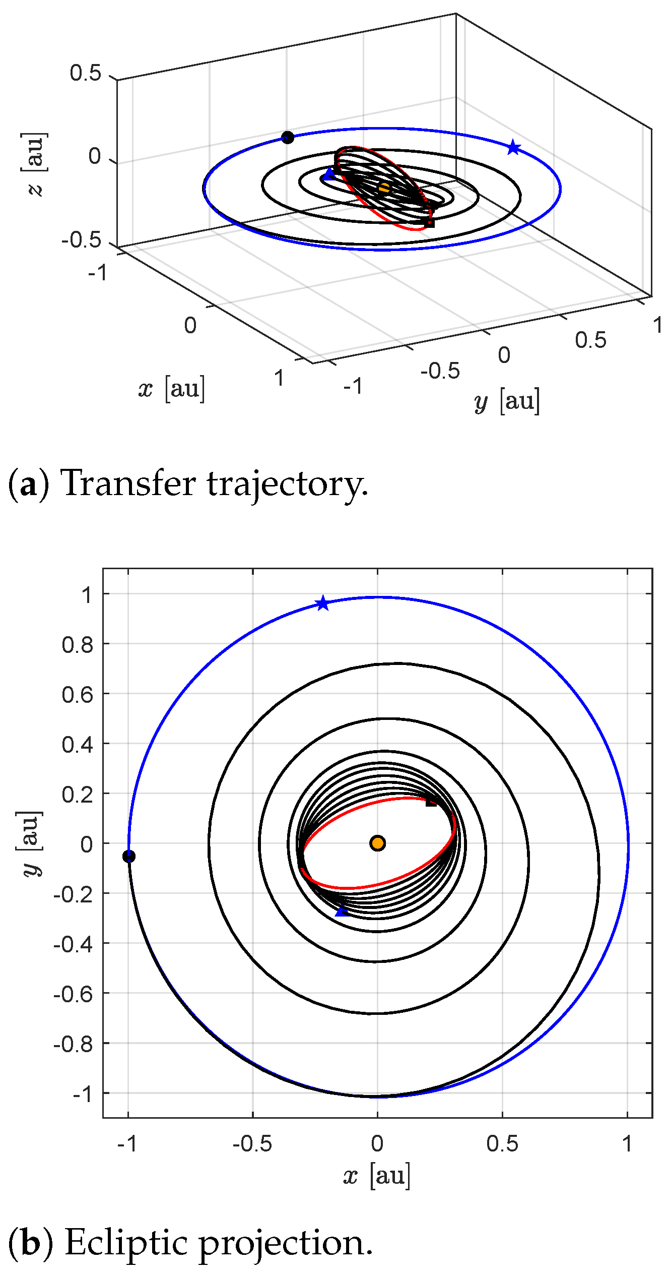
As expected, the spacecraft trajectory tends to reach a minimum distance below , but does not fall below (dashed red line). In the second phase, the distance from the Sun varies slightly with small fluctuations, while the inclination increases until it reaches the final desired value. The overall trajectory is shown in Figure 5, where the blue star represents the perihelion of the Earth’s heliocentric orbit.

Figure 5.
Near-optimal trajectory to a circular heliocentric orbit of radius and inclination using the two-phase strategy (). Black circle → start; black square → arrival; blue triangle → first phase end; blue star → perihelion; orange circle → the Sun; blue line → parking orbit; red line → target orbit; black line → transfer trajectory.
4. Performance Assessment of Two-Phase Strategy
The previous section described the two-phase strategy for generating near-optimal trajectories that combine the peculiarities of locally optimal methodologies (in terms of simplicity and effectiveness) with those of globally optimal approaches (ability to satisfy boundary conditions and obtain accurate solutions). Such a two-phase strategy, consisting of an approach phase and a cranking phase, is simple to implement numerically and is thus able to provide an approximate solution that is particularly useful in the initial phase of a mission analysis, where many feasible trajectories can be generated at a low computational cost.
It is interesting to verify whether the solutions obtained with the above strategy are indeed near-optimal, that is, whether they deviate by a few percentage points from an optimal solution. To answer this question and quantify this difference, we will compare the results that can be obtained in a reference case similar to the one described in the previous section, but using different data in terms of characteristic acceleration and constraint on the minimum distance from the Sun. More precisely, the reference case is taken from the mission scenario discussed in Ref. [21] and recently analyzed by Chu et al. [30] through the use of a local optimization approach. The mission objective is again to place the satellite in a target circular orbit around the Sun with a radius and an inclination of with respect to the Ecliptic, but in this case the spacecraft is propelled by an ideal diffractive sail with a characteristic acceleration . For the sake of comparison, the distance of the minimum approach from the Sun was set as equal to , the same as that used in Ref. [30], although this value is probably too small to be used in a real mission [27]. We begin this study by calculating minimum-time trajectories to a circular orbit of radius and different values of final inclination, increasing the latter by with each new simulation. The results obtained are summarized in Figure 6.
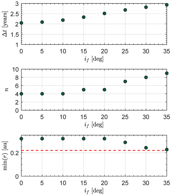
Figure 6.
Simulations of optimal trajectories with to a circular heliocentric orbit of radius for different values of final orbital inclination. Dashed red line → minimum solar distance.
As in the case discussed in the previous section, the minimum distance from the Sun tends to decrease for final inclinations greater than about , and the minimum distance equal to is reached for final inclinations of about . Therefore, the two-phase strategy in this case consists of a first approaching phase that ends on an osculating orbit with and inclination , and is connected with the second cranking phase in which the final distance still remains equal to , but the inclination rises to . The results are summarized in Figure 7.
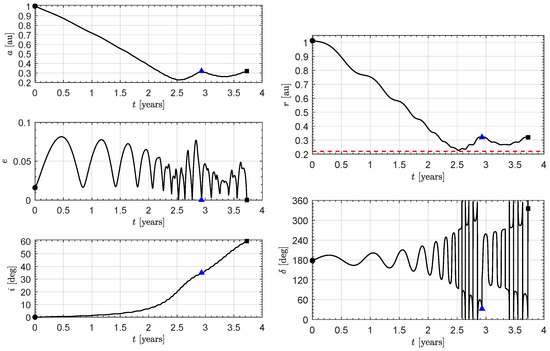
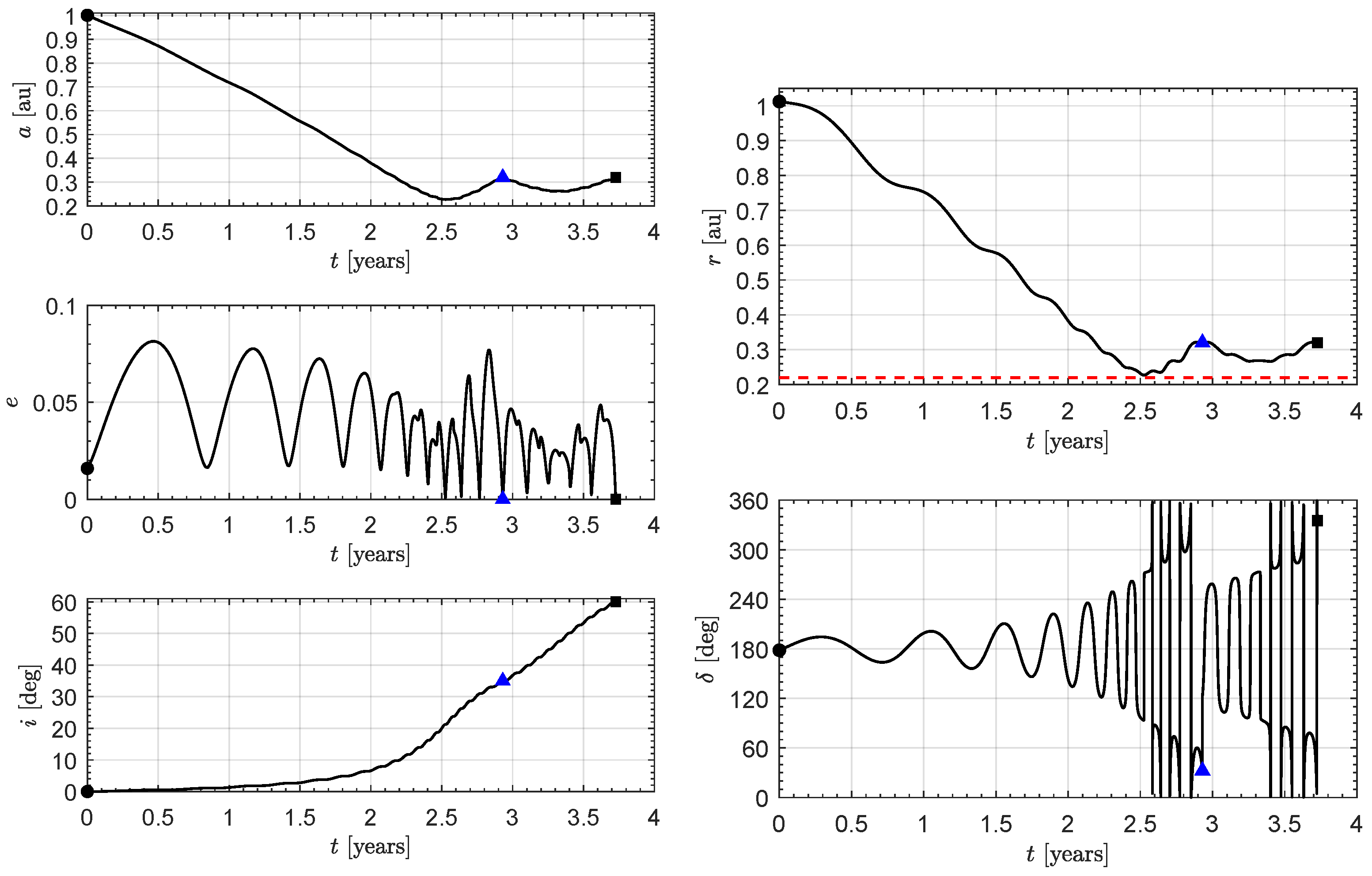
Figure 7.
Time variation of orbital parameters and control variable in a near-optimal transfer to a circular heliocentric orbit of radius and inclination using the two-phase strategy (). Black circle → start; black square → arrival; blue triangle → first phase end; dashed red line → minimum solar distance.
During the first phase, the distance from the Sun decreases until it reaches the minimum distance constraint after about , and then rises again to the distance of . During the second cranking phase, the spacecraft tends to slightly decrease its distance from the Sun, without approaching the minimum value, while the orbital inclination increases monotonically with small oscillations. The transfer trajectory found is shown in Figure 8. The duration of the first phase is , and that of the second phase is for a total of . These results are close to those reported by Chu et al. [30], who found a total time of for the same transfer, albeit using a more complex locally optimal control law than the one proposed in this paper. To further quantify the performance of the two-phase strategy, an optimal transfer was calculated using an indirect method [19] with the intermediate constraint of . The results of the simulations are shown in Figure 9, while the minimum-time trajectory is reported in Figure 10.
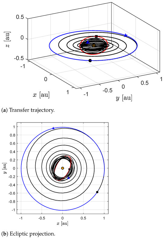
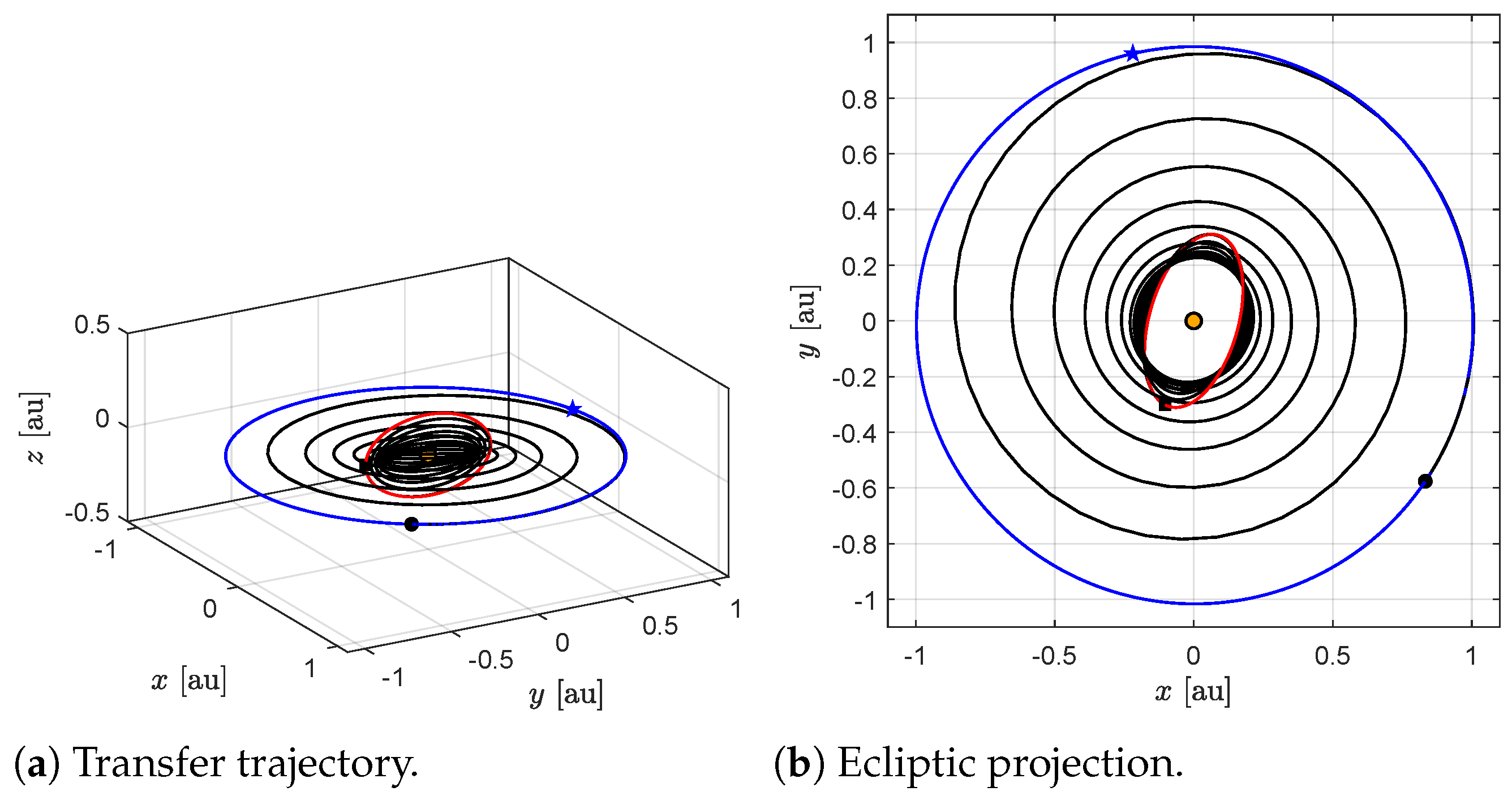
Figure 8.
Near-optimal trajectory to a circular heliocentric orbit of radius and inclination using the two-phase strategy (). Black circle → start; black square → arrival; blue triangle → first phase end; blue star → perihelion; orange circle → the Sun; blue line → parking orbit; red line → target orbit; black line → transfer trajectory.
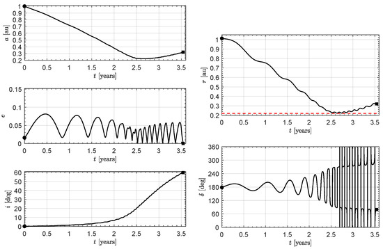
Figure 9.
Time variation of orbital parameters and control variable in an optimal transfer to a circular heliocentric orbit of radius and inclination (). Black circle → start; black square → arrival; dashed red line → minimum solar distance.
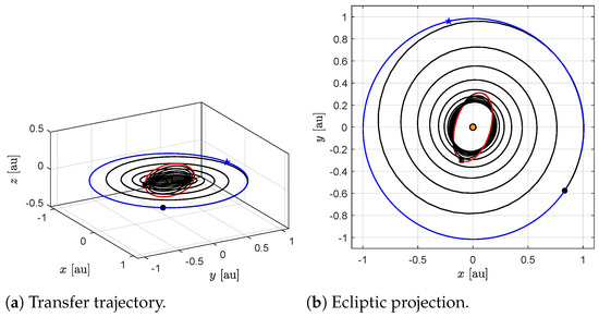
Figure 10.
Optimal trajectory to a circular heliocentric orbit of radius and inclination (). Black circle → start; black square → arrival; blue star → perihelion; orange circle → the Sun; blue line → parking orbit; red line → target orbit; black line → transfer trajectory.
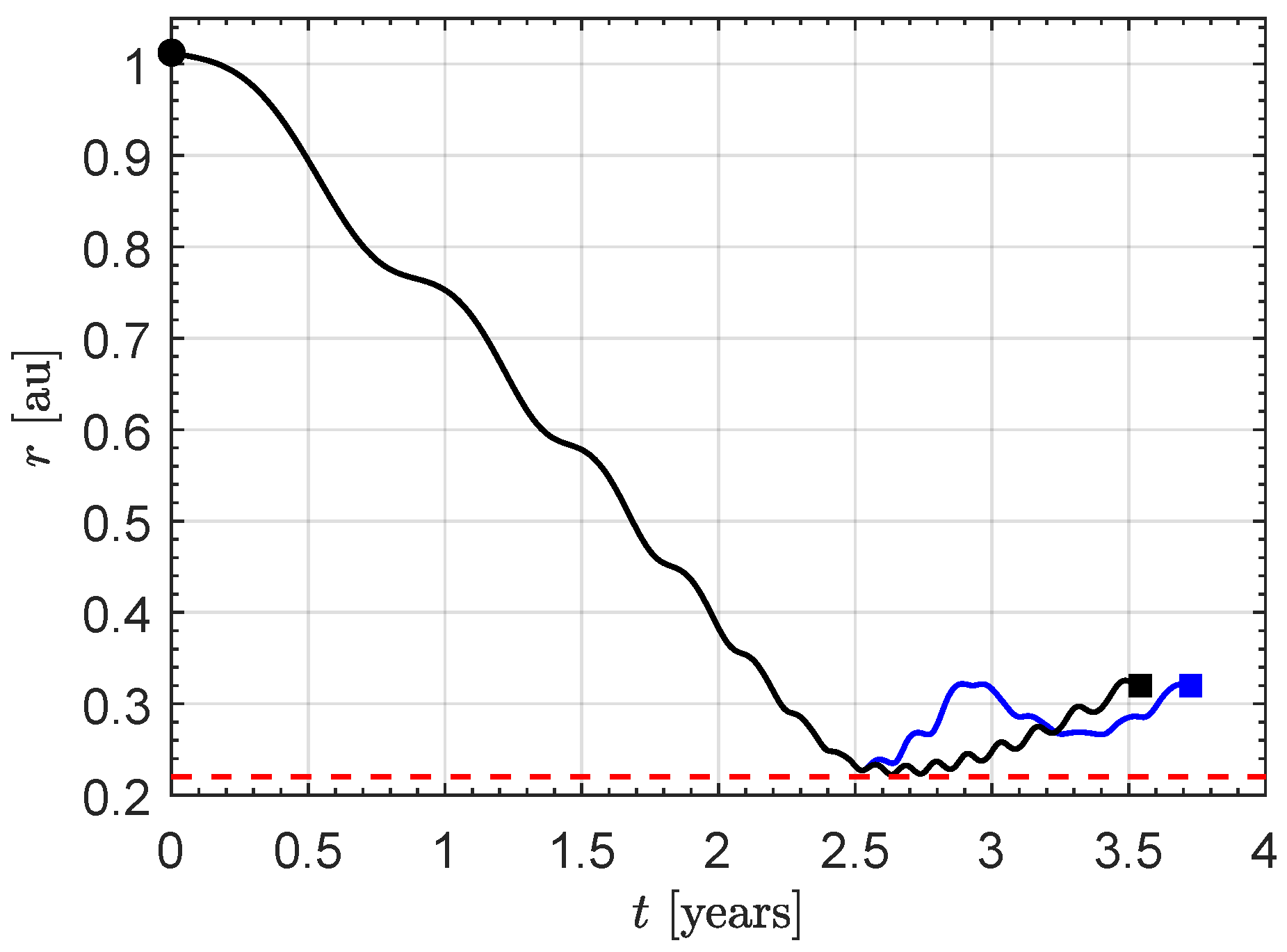
In contrast to the two-phase strategy, in this case the spacecraft moves for a fairly long period, approximately (i.e., almost of the total transfer time) while maintaining a distance from the Sun close to the minimum admissible value, in order to maximize the boosting effect due to the increased solar radiation pressure. The difference between the two-phase strategy and the optimal transfer is clearly visible in Figure 11.
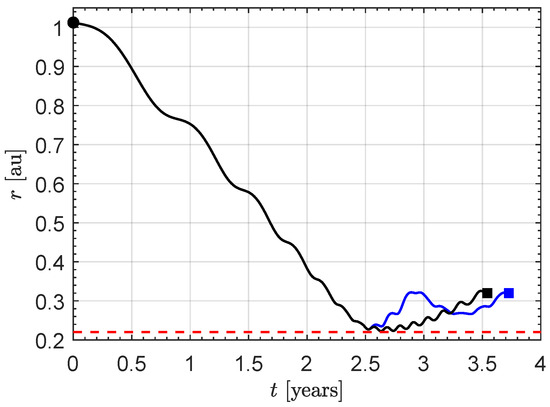
Figure 11.
Comparison of the two-phase strategy (blue line) and the optimal control law (black line) with . Dashed red line → minimum solar distance; filled circle → start; filled square → arrival.
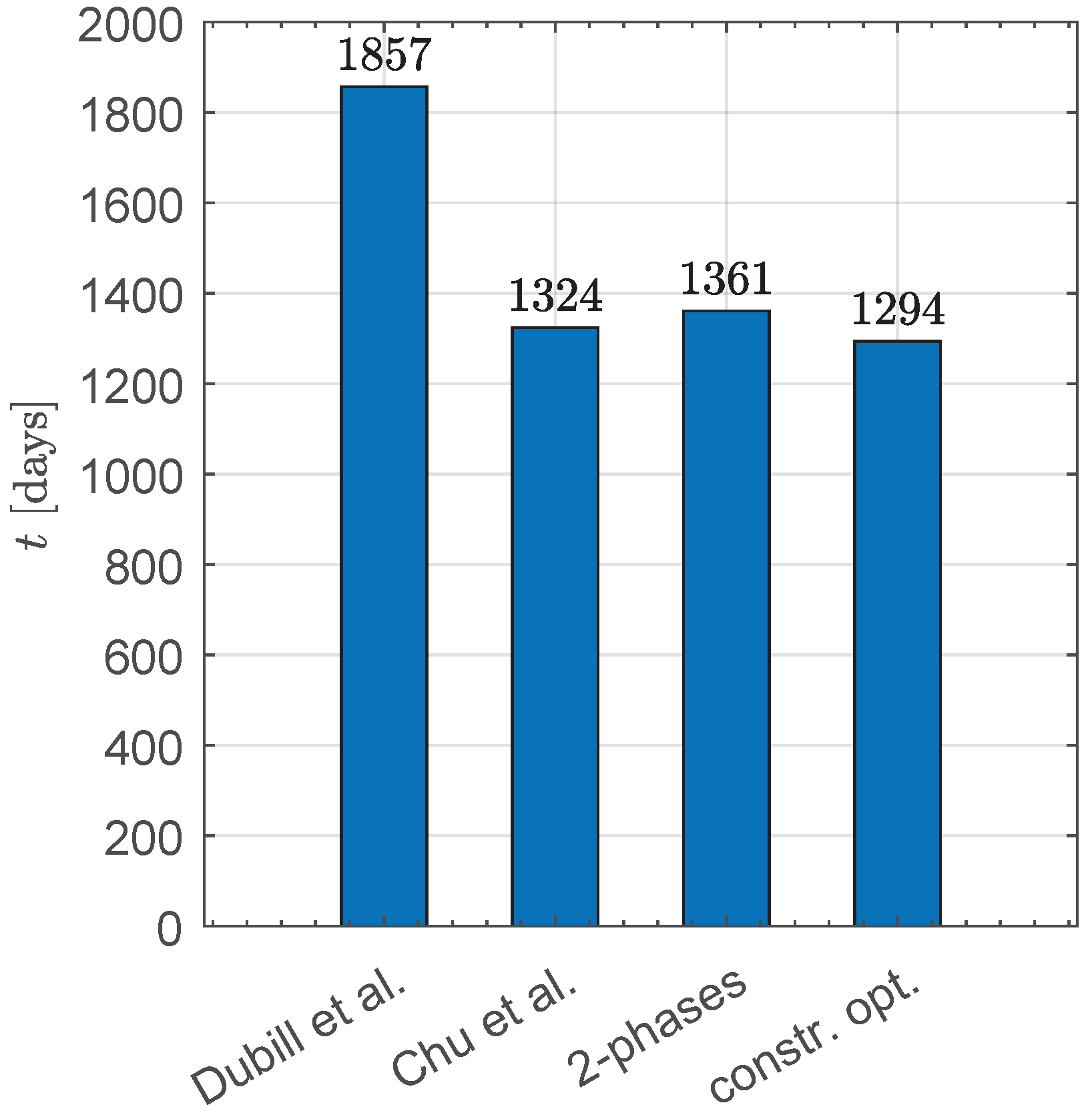
The total transfer time in the optimal case is , so that the two-phase strategy effectively determines a near-optimal solution, with a difference of (equivalent to an error of only ) compared to the optimal solution. Figure 12 shows a simple comparison of the various solutions available in the literature, in terms of flight times, including the simple non-optimal solution proposed by Dubill and Swartzlander [21].
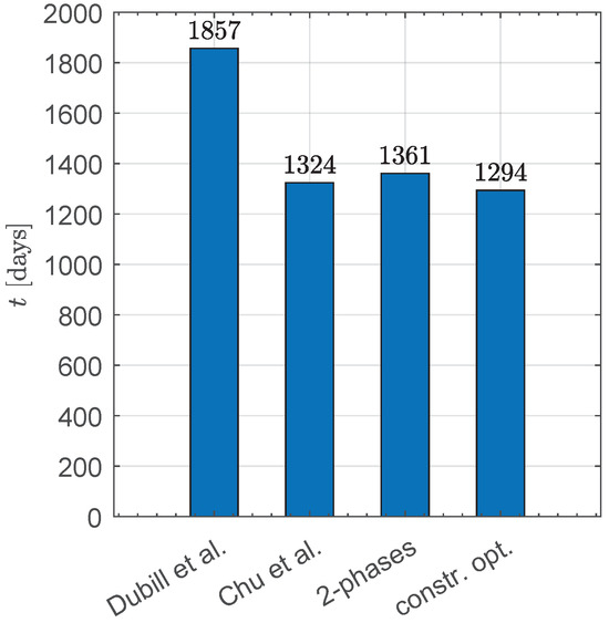
Figure 12.
Comparison of flight times obtained with various transfer strategies: Dubill et al. [21], Chu et al. [30], two-phase strategy, and optimal result ().
5. Conclusions
Reaching orbits with a high inclination relative to the Ecliptic in order to observe the polar regions of the Sun requires the use of unconventional propulsion systems to simplify the interplanetary trajectory design, i.e., to avoid the use of a number of planetary gravity-assist maneuvers. Solar sails seem to offer an excellent option for such challenging missions and, in that context, diffractive sails show several advantages, especially in terms of simplicity of attitude control, over the more common reflective counterparts.
The numerical simulation of the minimum-time trajectory to transfer a diffractive sail to the final circular orbit around the Sun is rather complex, but this paper has shown that a near-optimal solution can be obtained in a sufficiently simple way by splitting the transfer flight into two phases: (i) a first approach phase to a circular orbit of the same radius as the final orbit but with a smaller inclination; and (ii) a second cranking phase, in which the orbital plane is rotated until the desired inclination is reached. During the first phase, the minimum distance from the Sun does not fall below a minimum value compatible with the maximum thermal load that the diffractive sail can withstand. Simulations have shown that this strategy is indeed near-optimal, in the sense that flight times differ by less than 5% from those achievable with an optimal strategy.
Author Contributions
Conceptualization, G.M.; methodology, A.A.Q.; software, A.A.Q.; writing—original draft preparation, G.M.; writing—review and editing, A.A.Q. and G.M. All authors have read and agreed to the published version of the manuscript.
Funding
This research received no external funding.
Institutional Review Board Statement
Not applicable.
Informed Consent Statement
Not applicable.
Data Availability Statement
Data are contained within the article.
Conflicts of Interest
The authors declare no conflicts of interest.
Abbreviations
| a | semimajor axis [au] |
| characteristic acceleration [mm/s2] | |
| propulsive acceleration vector [mm/s2] | |
| e | orbital eccentricity |
| i | orbital inclination [deg] |
| target orbit inclination [deg] | |
| maximum inclination with unconstrained transfer [deg] | |
| unit vectors of radial–tangential–normal reference frame | |
| unit vectors of body-fixed reference frame | |
| n | number of complete revolutions around the Sun |
| r | distance from the Sun [au] |
| minimum solar distance constraint [au] | |
| target orbit radius [au] | |
| reference distance [] | |
| t | time [days] |
| sail clock angle [deg] |
References
- Zouganelis, I.; De Groof, A.; Walsh, A.P.; Williams, D.R.; Müller, D.; St Cyr, O.C.; Auchère, F.; Berghmans, D.; Fludra, A.; Horbury, T.S.; et al. The Solar Orbiter Science Activity Plan. Translating solar and heliospheric physics questions into action. Astron. Astrophys. 2020, 642, A3. [Google Scholar] [CrossRef]
- Velli, M.; Harra, L.K.; Vourlidas, A.; Schwadron, N.; Panasenco, O.; Liewer, P.C.; Müller, D.; Zouganelis, I.; St Cyr, O.C.; Gilbert, H.; et al. Understanding the origins of the heliosphere: Integrating observations and measurements from Parker Solar Probe, Solar Orbiter, and other space- and ground-based observatories. Astron. Astrophys. 2020, 642, A4. [Google Scholar] [CrossRef]
- Circi, C. Lunar Base for Mars Missions. J. Guid. Control Dyn. 2005, 28, 372–377. [Google Scholar] [CrossRef]
- Wenzel, K.P.; Marsden, R.G.; Page, D.E.; Smith, E.J. The Ulysses Mission. Astron. Astrophys. Suppl. 1992, 92, 207–219. [Google Scholar]
- García Marirrodriga, C.; Pacros, A.; Strandmoe, S.; Arcioni, M.; Arts, A.; Ashcroft, C.; Ayache, L.; Bonnefous, Y.; Brahimi, N.; Cipriani, F.; et al. Solar Orbiter: Mission and spacecraft design. Astron. Astrophys. 2021, 646, A121. [Google Scholar] [CrossRef]
- O’Reilly, D.; Herdrich, G.; Kavanagh, D.F. Electric Propulsion Methods for Small Satellites: A Review. Aerospace 2021, 8, 22. [Google Scholar] [CrossRef]
- Circi, C. Properties of transit trajectory in the restricted three and four-body problem. Adv. Space Res. 2012, 49, 1506–1519. [Google Scholar] [CrossRef]
- Circi, C. Mars and Mercury Missions Using Solar Sails and Solar Electric Propulsion. J. Guid. Control Dyn. 2004, 27, 496–498. [Google Scholar] [CrossRef]
- Goldstein, B.; Buffington, A.; Cummings, A.C.; Fisher, R.; Jackson, B.V.; Liewer, P.C.; Mewaldt, R.A.; Neugebauer, M. A Solar Polar Sail Mission: Report of a Study to Put a Scientific Spacecraft in a Circular Polar Orbit about the Sun. In Proceedings of the SPIE International Symposium on Optical Science, Engineering and Instrumentation, San Diego, CA, USA, 2 November 1998. [Google Scholar] [CrossRef]
- Sauer, C.G., Jr. Solar Sail Trajectories for Solar Polar and Interstellar Probe Missions. In Proceedings of the AAS/AIAA Astrodynamics Specialist Conference, Girdwood, AK, USA, 15–19 August 1999. [Google Scholar]
- Dachwald, B.; Ohndorf, A.; Wie, B. Solar sail trajectory optimization for the Solar Polar Imager (SPI) mission. In Proceedings of the AIAA/AAS Astrodynamics Specialist Conference and Exhibit, Keystone, CO, USA, 21–24 August 2006. [Google Scholar] [CrossRef]
- Macdonald, M.; Hughes, G.W.; McInnes, C.R.; Lyngvi, A.; Falkner, P.; Atzei, A. Solar Polar Orbiter: A Solar Sail Technology Reference Study. J. Spacecr. Rocket. 2006, 43, 960–972. [Google Scholar] [CrossRef]
- Thomas, D.; Kobayashi, K.; Mike, B.; Bean, Q.; Capizzo, P.; Clements, K.; Fabisinski, L.; Garcia, J.; Steve, S. Solar Polar Imager Concept. In Proceedings of the ASCEND 2020, Virtual, 16–18 November 2020. [Google Scholar] [CrossRef]
- Swartzlander, G.A., Jr. Radiation pressure on a diffractive sailcraft. J. Opt. Soc. Am. Opt. Phys. 2017, 34, C25–C30. [Google Scholar] [CrossRef]
- Swartzlander, G.A., Jr. Flying on a rainbow: A solar-driven diffractive sailcraft. JBIS J. Br. Interplanet. Soc. 2018, 71, 130–132. [Google Scholar]
- Srivastava, P.R.; Lucy Chu, Y.J.; Swartzlander, G.A., Jr. Stable diffractive beam rider. Opt. Lett. 2019, 44, 3082–3085. [Google Scholar] [CrossRef]
- Swartzlander, G.A., Jr. Theory of radiation pressure on a diffractive solar sail. J. Opt. Soc. Am. B Opt. Phys. 2022, 39, 2556–2563. [Google Scholar] [CrossRef]
- McInnes, C.R. Passive control of displaced solar sail orbits. J. Guid. Control. Dyn. 1998, 21, 975–982. [Google Scholar] [CrossRef]
- Quarta, A.A.; Mengali, G.; Bassetto, M.; Niccolai, L. Optimal interplanetary trajectories for Sun-facing ideal diffractive sails. Astrodynamics 2023, 7, 285–299. [Google Scholar] [CrossRef]
- Chu, Y.; Baoyin, H.; Gong, S. Dynamics and control of sun-facing diffractive solar sails in displaced orbit for asteroid deflection. Aerosp. Sci. Technol. 2024, 145, 1–12. [Google Scholar] [CrossRef]
- Dubill, A.L.; Swartzlander, G.A., Jr. Circumnavigating the Sun with diffractive solar sails. Acta Astronaut. 2021, 187, 190–195. [Google Scholar] [CrossRef]
- Chu, Y.; Firuzi, S.; Gong, S. Controllable liquid crystal diffractive sail and its potential applications. Acta Astronaut. 2021, 182, 37–45. [Google Scholar] [CrossRef]
- Quarta, A.A.; Mengali, G. Solar sail orbit raising with electro-optically controlled diffractive film. Appl. Sci. 2023, 13, 7078. [Google Scholar] [CrossRef]
- Bassetto, M.; Quarta, A.A.; Mengali, G. Diffractive sail-based displaced orbits for high-latitude environment monitoring. Remote Sens. 2023, 15, 5626. [Google Scholar] [CrossRef]
- Casini, S.; Fodde, I.; Monna, B.; Cervone, A.; Gill, E. Novel 3U Stand-Alone CubeSat Architecture for Autonomous Near Earth Asteroid Fly-By. Aerospace 2020, 8, 9. [Google Scholar] [CrossRef]
- Johnson, L.; Castillo-Rogez, J.; Lockett, T. Near Earth asteroid Scout: Exploring asteroid 1991VG using a Smallsat. In Proceedings of the International Astronautical Congress (IAC), Washington, DC, USA, 21–25 October 2019. [Google Scholar]
- Mengali, G.; Quarta, A.A. Solar Sail Near-Optimal Circular Transfers with Plane Change. J. Guid. Control Dyn. 2009, 32, 456–463. [Google Scholar] [CrossRef]
- Dachwald, B. Optimal solar sail trajectories for missions to the outer solar system. J. Guid. Control Dyn. 2005, 28, 1187–1193. [Google Scholar] [CrossRef]
- Wie, B.; Thomas, S.; Paluszek, M.; Murphy, D. Propellantless AOCS Design for a 160-m, 450-kg Sailcraft of the Solar Polar Imager Mission. In Proceedings of the 41st AIAA/ASME/SAE/ASEE Joint Propulsion Conference & Exhibit, Tucson, AZ, USA, 10–13 July 2005. [Google Scholar] [CrossRef]
- Chu, Y.; Wu, D.; Gong, S. Enhanced Transfer Performance of Sun-Facing Diffractive Sails in Solar Polar Imager Missions. Adv. Space Res. 2024, 73, 4827–4841. [Google Scholar] [CrossRef]


Disclaimer/Publisher’s Note: The statements, opinions and data contained in all publications are solely those of the individual author(s) and contributor(s) and not of MDPI and/or the editor(s). MDPI and/or the editor(s) disclaim responsibility for any injury to people or property resulting from any ideas, methods, instructions or products referred to in the content. |
© 2024 by the authors. Licensee MDPI, Basel, Switzerland. This article is an open access article distributed under the terms and conditions of the Creative Commons Attribution (CC BY) license (https://creativecommons.org/licenses/by/4.0/).