Article

GPS-Induced Disparity Correction for Accurate Object Placement in Augmented Reality

1
Department of Information & Communication Engineering, Wonkwang University, Iksan 54538, Republic of Korea
2
DAXIB Inc., Smart Building 321, Jeju 63309, Republic of Korea
3
Department of Computer Software Engineering, Wonkwang University, Iksan 54538, Republic of Korea
*
Authors to whom correspondence should be addressed.
Appl. Sci. 2024, 14(7), 2849; https://doi.org/10.3390/app14072849
Submission received: 3 February 2024 / Revised: 13 March 2024 / Accepted: 26 March 2024 / Published: 28 March 2024
(This article belongs to the Special Issue User Experience in Virtual Environments)

Abstract

:
The use of augmented reality (AR) continues to increase, particularly in marketing and advertising, where virtual objects are showcased in the AR world, thereby expanding its various applications. In this paper, a method of linking coordinate systems to connect the metaverse with the real world is proposed and a system for correcting and displaying virtual objects in the AR environment is implemented. The proposed method calculates errors to accurately represent virtual objects in AR and presents a method to show these objects without errors. The proposed method was verified through experiments to successfully display virtual objects in AR. To minimize localization errors, semantic segmentation was used to recognize objects and estimate buildings, thereby correcting the device location. An error correction expression is also presented. The proposed system is designed to correct and display virtual objects in AR, with confirmed functionality for location correction.

1. Introduction

Augmented reality (AR) merges the real and virtual worlds, enriching user experience with overlaid virtual elements. Combined with digital twin technology, AR offers precise virtual replicas of real environments, thereby enhancing the accuracy of the information presented [1,2]. This synergy is highly beneficial in advertising, where AR with digital twins allow businesses to deliver engaging and interactive advertising experiences, boosting consumer engagement by offering real-time product and service information. Educational AR applications [3] also elucidate its potential for advertising, particularly in consumer education and product demonstrations. Research in the automotive industry [4] provides insights into effective advertising object placement in AR, illustrating the interaction between virtual and real-world elements. Furthermore, the use of urban digital twins and drones to visualize future landscapes [5] demonstrates an effective combination of real-time data and 3D modeling in AR advertising. These technologies collectively offer innovative advertising methods and promising personalized and interactive consumer experiences, achieving significant progress in the advertising industry [6].
The integration of sophisticated building classification algorithms is pivotal for refining AR technologies, particularly in urban and complex architectural environments. Previous studies have provided a comprehensive survey of three-dimensional (3D) object recognition in cluttered scenes, highlighting how detailed building surface features can be leveraged to improve AR image accuracy [7]. Real-object recognition and localization in an AR environment have been addressed based on simultaneous localization and mapping (SLAM), a technique that is crucial for accurately overlaying virtual images onto real-world buildings [8]. Further, a mobile outdoor AR method combining deep-learning object detection with spatial relationships for geovisualization has been proposed. This approach is instrumental in precisely mapping AR objects onto the corresponding physical buildings, ensuring seamless integration of virtual and real elements [9]. Finally, markerless pose tracking for AR delves into the nuances of accurately aligning virtual images with physical structures without the need for physical markers, a method that significantly improves user experience in AR applications [10].
To address the challenge of global positioning system (GPS) inaccuracies, a pivotal aspect of enhancing the AR experience lies in GPS-induced error detection and correction. Previous research has shed light on the existing technologies and methodologies for such purpose. These previous studies explored various approaches to identify and mitigate GPS inaccuracies, which are critical for ensuring the precise placement of AR elements in real-world coordinates. Advanced techniques in image-based localization and camera-pose estimation have been discussed, which play a significant role in GPS error compensation [11]. Correcting geometric distortions in stereoscopic 3D imaging is intimately linked to accurate GPS positioning [12]. The fusion of map and satellite data for outdoor localization, which highlights the importance of integrating multiple data sources to enhance the accuracy of GPS systems in AR applications, has been explored [13,14]. Collective efforts to refine GPS accuracy are fundamental for advancing the reliability and usability of AR technology in various settings.
A critical component in the realm of AR is the advancement of camera-position estimation and 3D imaging technologies. Previous studies have emphasized the significance of these technologies for AR environments. Innovative methods for camera-pose estimation, a fundamental aspect that determines the accuracy and effectiveness of AR applications, have been explored [15,16]. Precise camera localization is paramount to ensure that virtual elements align correctly with the real world [17,18]. An overview of image-based camera-localization techniques, which are essential for the seamless integration of 3D elements into physical spaces, was presented in [19]. These advancements in camera position estimation and 3D imaging not only enhance the user experience by providing more realistic and immersive AR scenarios but also extend the potential applications of AR technology to various fields, including navigation, gaming, and education. This collective body of work underscores the ongoing innovations and improvements in camera technology essential for the evolution of AR.
These studies provide insight into the vast potential of AR across various sectors, emphasizing its transformative impact on marketing, education, and beyond [20,21]. However, they also highlight the need for improved localization techniques to ensure that AR content, particularly advertising objects, is displayed accurately and reliably in the user’s environment. Accordingly, the current study addresses this issue by proposing a solution for enhancing the placement and visibility of AR advertising objects. We suggest a method that not only improves the accuracy of object localization in AR but also contributes to a more immersive and engaging user experience. This approach is not only a step forward in the realm of AR advertising but also sets the stage for broader AR technology applications. By addressing these localization challenges, we aim to unlock the full potential of AR and pave the way for more advanced practical applications in various fields.
Studies have been conducted on the mapping and recognition of the location of objects and users. Methods utilizing markers for AR placement have been explored; however, they entail the inconvenience of physically installing markers, which are impractical for outdoor environments [22]. Additionally, indoor-based approaches lack adequate outdoor application [23]. Although outdoor AR solutions employing GPS have been proposed, the inaccuracies associated with GPS can significantly hinder the precise localization and recognition of objects [24]. This study aims to address these challenges by proposing a technique that not only accurately displays objects within the AR environment but also corrects their positioning, thus enhancing both the user experience and the accuracy of AR advertising objects.
The remainder of this paper is organized as follows: Section 2 encompasses both the original system architecture and the exploration of 3D object display in AR environments. Section 3 details the experimental validation of our system, emphasizing the methods used for the AR image display and positional accuracy. Finally, Section 4 summarizes the study, presents our main conclusions, and points to avenues for future research in this field.

2. Materials and Methods

In this section, we provide an in-depth mathematical treatment for accurate 3D object rendering in AR, encompassing coordinate mapping between a virtual object coordinate system and a GPS coordinate frame through three-point matching, camera-pose estimation and rectification, and transformations between the object coordinate space and image plane coordinate system.

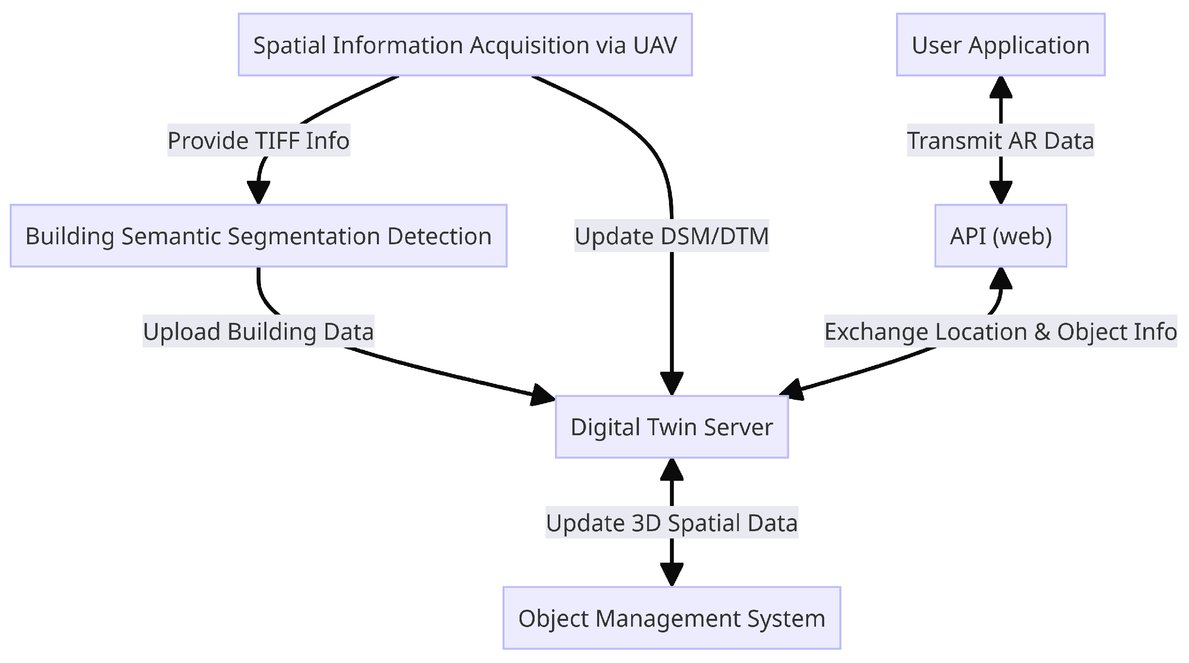
2.1. Framework for Object Rendering in Augmented Reality

As depicted in Figure 1, the proposed system introduces an advanced framework for acquiring and refining AR imagery and location data. The system’s cornerstone, the “Digital Twin Server”, hosts a comprehensive repository of 3D spatial information, including latitude, longitude, and a versatile virtual coordinate system for object management and registration. This server not only stores detailed building information but also integrates digital elevation model (DEM) and digital terrain model (DTM) updates provided by the “Spatial Information Acquisition via UAV (Unmanned Aerial Vehicle)” component. The DSM and DTM are instrumental in depicting the Earth’s surface and terrain morphology, respectively, thereby enhancing the precision of digital twins for AR applications. The “Spatial Information Acquisition via UAV” segment deploys drones to capture imagery, which includes crucial GPS coordinate information embedded in TIFF files. These files are processed by the “Building Semantic Segmentation Detection” module, where semantic segmentation extracts geolocation data as building polygons, enriching the digital twin database. This process benefits from cross-referencing public building records, ensuring that the building height data of the DT server remain updated. To facilitate dynamic interactions with AR objects, the “Object Management System” oversees the registration and management of items within a virtual coordinate framework. End-users interact with these AR objects through the “User Application”, which communicates with the digital twin server via the “API (web)”. This interaction enables the server to retrieve and display object information based on user location data, ensuring a seamless and interactive AR experience.

2.2. Coordinate Mapping for 3D Object Rendering in AR

A separate coordinate system is used to facilitate the rendering of various 3D objects. This allows easy adjustment of the 3D object size and position, making the objects more readily displayable on AR devices. The Digital Twin Server maintains both the 3D object coordinate system and the latitude, longitude, and elevation coordinates of the building. Critical processes include 3D object creation and three-point matching execution on AR devices. Three-point matching refers to the task of mapping the object coordinate system to the GPS coordinate system. Once the mapping is complete, the app can retrieve and display 3D object information from the server using the building information in the object coordinate system to properly overlay the objects in the AR environment. As illustrated in Figure 2, once three-point matching is completed, objects denoted as OBJ can be rendered using the acquired building coordinates. However, errors in the GPS position, such as with points A, B, and C, can lead to location inaccuracies. Therefore, it is imperative to correct the device location and ensure perfect image rendering through semantic segmentation.

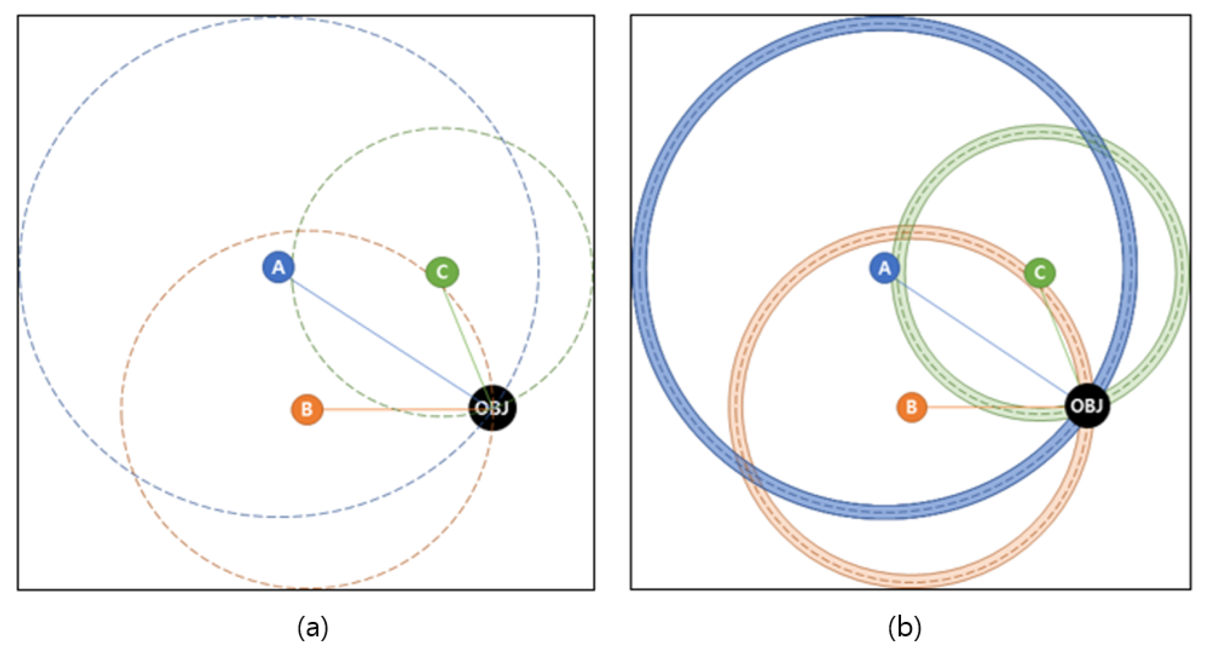
2.3. Localization of 3D Objects

Understanding the position and orientation of the camera is vital to transform 3D spatial coordinates into 2D image coordinates. This concept is often referred to as the rigid body transformation of a camera. Consider an object located in 3D space, designated by coordinates P ( x , y , z ) . In AR, the positioning of a virtual object can be estimated using the physical location of the camera and GPS data correlating to a specific real-world location.
First, let us consider rigid-body transformation. Conversion of the 3D position into the camera coordinate system involves a series of rotations and translations determined by the camera’s accurate positioning and orientation data obtained via GPS. This transformation is essential for precisely locating the camera in space. The 3D coordinates are then projected onto a 2D image plane by utilizing the intrinsic parameters of the camera, such as the focal length and sensor attributes. This projection process generates image coordinates ( x pixel , y pixel ) , indicating the 3D point’s horizontal and vertical positions in the 2D image frame.
However, in real-world applications, discrepancies in camera positioning, primarily due to GPS inaccuracies, can occur. These discrepancies lead to a scenario in which the rigid-body transformation, now with GPS errors, presents positional deviations. Targeting the same 3D point P, this altered transformation yields a different set of 2D coordinates on the image plane, denoted ( x pixel _ error , y pixel _ error ) . These coordinates reflect the incorrect projection of the same 3D point, which is attributed to deviations in the rigid-body transformation of the perturbed camera.
Comparing P with P e reveals the impact of camera positioning errors on the precision of projecting 3D points onto a 2D plane. This insight is particularly crucial in AR for accurate mapping and object localization. The rotation matrix in the context of 3D space is a fundamental aspect of camera characteristics, representing the rotation of an object or coordinate system in three dimensions. Let us now explore the derivation of a 3D rotation matrix, commonly denoted as R. In the XYZ coordinate system, rotation can occur around the principal X, Y, and Z axes. These rotations are typically described using Euler angles: roll ( ϕ ) , pitch ( θ ) , and yaw ( ψ ) . The matrices for these rotations are as follows:
The roll around the X-axis is denoted as
R x ( ϕ ) = 1 0 0 0 cos ( ϕ ) sin ( ϕ ) 0 sin ( ϕ ) cos ( ϕ ) .
The pitch around the Y-axis is denoted as
R y ( θ ) = cos ( θ ) 0 sin ( θ ) 0 1 0 sin ( θ ) 0 cos ( θ ) .
Finally, the yaw around the Z-axis is denoted as
R z ( ψ ) = cos ( ψ ) sin ( ψ ) 0 sin ( ψ ) cos ( ψ ) 0 0 0 1 .
The combined rotation matrix R, representing rotations in the Z-Y-X sequence (i.e., yaw-pitch-roll), is defined as the product of the individual matrices, denoted as (1), (2), and (3), respectively, collectively forming
R z ( ψ ) · R y ( θ ) · R x ( ϕ )
This matrix is crucial for rotating a point or coordinate frame in 3D space, and the specific multiplication order (Z-Y-X) indicates the non-commutative nature of matrix multiplication in rotations. To compute the rigid-body transformation of a camera in 3D space, both rotation and translation are involved. This transformation is pivotal for mapping points from one coordinate system to another. The detailed process is described next.
A rigid body transformation in 3D space comprises both rotation, which can be derived using (4) to obtain R, a 3 × 3 matrix representing the rotation, and translation, represented by vector T = ( t _ x , t _ y , t _ z ) . This matrix formulates the following transformation:
R 1 0 1 I T 0 1 = R R T 0 1
To transform a point P = ( x , y , z ) using this transformation, with and without GPS error, the following steps were taken:
In the case where GPS errors are incorporated, the position of an object projected into the camera space is represented as:
P e = R R T e 0 1 · P
Conversely, in the absence of GPS errors, the position of an object projected onto the camera space is represented as:
P = R R T 0 1 , · P
where P denotes the position of the object in the world coordinate system, and T e and T represent the translation vectors with and without errors, respectively.
The results are in homogeneous coordinates and must be converted back to Cartesian coordinates for practical applications. The intrinsic parameters of a camera, including the focal lengths f x and f y , principal points c x and c y , and skew coefficient, define its internal characteristics. The intrinsic matrix K that encapsulates these parameters is as follows:
K = f x 0 c x 0 f y c y 0 0 1
The transformation of a world coordinate point P world = ( x , y , z ) into the camera coordinate system involves the use of the extrinsic parameters of the camera (rotation R and translation T). This transformed point ( X , Y , Z ) is then projected onto the image plane ( u , v , w ) using the following intrinsic matrix:
u v w = K · X Y Z
In the final step, these homogeneous coordinates are converted into pixel coordinates in the image sensor as follows:
x pixel = u w , y pixel = v w
Using the differences in the image plane coordinates P and P e , we aim to determine the difference T delta in the GPS coordinates to pinpoint the camera’s exact location.
For erroneous pixel coordinates:
P e = Z · K 1 · x pixel _ error y pixel _ error 1
For reference pixel coordinates:
P = Z · K 1 · x pixel y pixel 1
We transform these points into world coordinates using the rotation matrix R. Upon applying the inverse rotation matrix to the world coordinates, we obtain
Z = R 1 P
where Z represents the point depth in the coordinate system of the camera. This depth is critical for accurately projecting a point onto a 2D image plane by leveraging the camera’s intrinsic matrix K. The intrinsic matrix then scales this depth along the X- and Y-coordinates to compute the final image coordinates, ensuring an accurate representation of the 3D world point on the 2D image.
P h e and P represent the transformation in the extended and basic environments, respectively. Calculating each transformation yields
P e = R · P + R · T e
P = R · P
Then, we can calculate T using the difference between P e and P as follows:
P e P = R · T e
Assuming that R is invertible (i.e., an inverse exists), to directly calculate T, we use
R 1 · ( P e P ) = T e
This calculation is valid under the assumption that the inverse of R exists and can be computed. To perform the actual calculation, specific values for R, P h e , and P h are needed.
Therefore, T can be calculated as follows:
T e = R 1 · ( P e P )
This depends on the actual values of R, P e , and P , Thus, we address the challenge of accurately determining the camera positioning in 3D space by considering potential GPS errors and their impact on 3D point projections in 2D imaging.
In our computational analysis, we sought to refine the estimation of the translation vector T, which represents the displacement from erroneous measurements to accurate world coordinates. Given a series of individual translation vectors T i , derived from multiple observations or point pairs, the most prevalent method for determining an optimal translation vector is to compute the mean of these vectors. Each translation vector T i is computed as the difference between the corresponding erroneous camera point P e and the reference world point P .
Then, the aggregate translation vector T mean is calculated as the average of all individual T i vectors as follows:
T mean = 1 n i = 1 n T i
where n is the total number of observations.
This averaging process effectively reduces the random errors present in individual observations under the assumption that these errors are unbiased and normally distributed. The calculation is performed by summing all individual translation vectors and then dividing by the number of vectors to yield the mean translation vector T mean .
From a least-squares error perspective, this approach is equivalent to minimizing the sum of the squared differences between T mean and each T i , thereby providing a robust estimate of the actual translation required to correct the measurement discrepancies.

3. Results

Here, we present the implementation of a 3D object-rendering AR application, focusing on methods to correct location errors caused by GPS inaccuracies and object occlusion by buildings, ensuring realistic and seamless integration of virtual objects within the real-world environment.

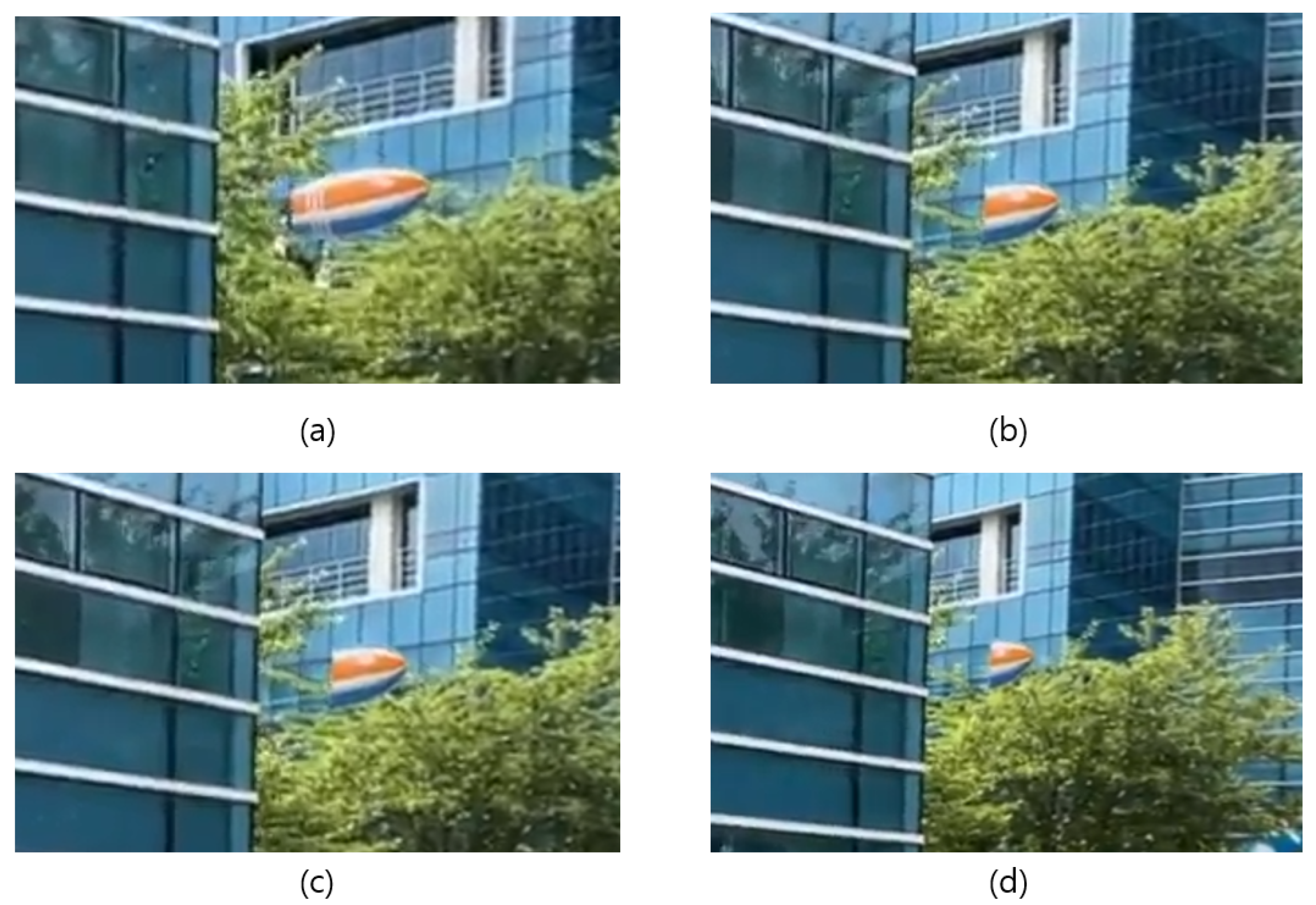
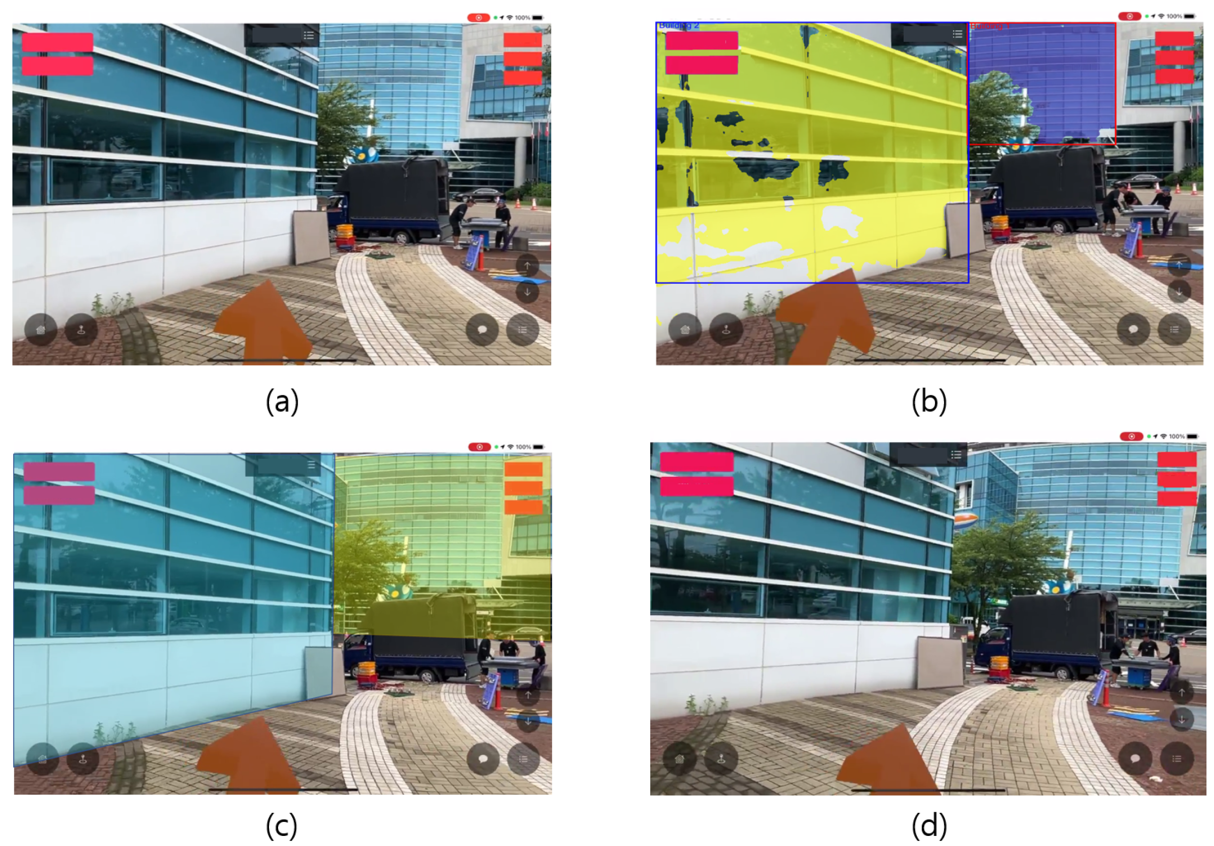
3.1. Results of 3D Object AR Rendering App Implementation and Location Correction

We focused on the development results of the AR rendering features of 3D objects rather than the server and building updates previously described. Figure 3 illustrates a promotional balloon floating between buildings. The server API retrieves the building’s GPS coordinates and height information corresponding to the coordinates of the object, which are then rendered by the application. Invisible barriers are set in the application to ensure proper object rendering. In the sequence of images presented in Figure 3a–d, the balloon’s apparent reduction in size as it moves leftward is not due to an actual decrease in size but rather a perspective effect caused by the balloon being obscured by buildings. This visual effect is a result of the viewing angle, where parts of the balloon become hidden, giving the illusion of shrinking. However, GPS inaccuracies contribute to further discrepancies, making the balloon seem partially cut off from the viewer’s perspective. The next step was to correct the appearance of the truncated balloon and adjust the location of the device. There are two methods to correct this: recalculating the location of the device, and using semantic segmentation to recognize different buildings and move the balloon accordingly. The selected method involved object segmentation, building recognition, and balloon movement.
As shown in Figure 4, object segmentation is specifically applied to isolate each building. Then, we established barriers corresponding to these segmented buildings to ensure that the balloon was correctly displayed. As shown, the building identified in (a) is segmented, as shown in (b), leading us to set up an arbitrary barrier, as depicted in (c). This step is crucial for maneuvering the balloon, culminating in the outcomes shown in (d). This sequence clearly demonstrates the precise alignment of the balloon with the buildings, illustrating the practical application of our segmentation and barrier setup process in enhancing the AR object display.
The proposed equations are used to validate the positional error correction method through numerical analysis. Figure 5 shows the procedure to validate these equations using MATLAB R2022, showcasing a distance and positioning relative to the camera, objects, and buildings for numerical analysis. The left side of the image displays a camera without errors, depicting its position and angle and how the image projects, as described above. Conversely, the right-hand camera shows the projection of the lower image affected by GPS errors, which serve as the basis for our numerical analysis. The rectangles in the left image symbolize buildings, representing real structures. In this depiction, we calculate the projections of P ( x , y , z ) into ( x pixel , y pixel ) and ( x pixel _ error , y pixel _ error ) .
Given the world coordinates of object P ( x , y , z ) as (21.6, 17.3, 8.4), this point is projected onto the camera space under both error-prone and error-free scenarios. The erroneous and correct image plane coordinates were determined to be ( 739.5421 , 366.0855 ) and ( 550.0000 , 360.0000 ) , respectively. These coordinates allowed us to directly observe the influence of GPS errors.
From Equations (11) and (12), we calculate P and P e using using these coordinates. Here, Z is determined using (13). By applying these transformations, we noted the differences between the projected positions with and without GPS errors as P P e = ( 6.8521 , 0.2200 , 0 ) . This discrepancy is crucial for understanding spatial errors introduced by GPS inaccuracies.
To address this issue, we calculated the translation vector T e , which represents the necessary adjustment to correct GPS-induced errors. Utilizing (17), we determined T e to be (4.4940, −5.6051, −0.0120). This calculation is predicted on the assumption that the rotation matrix R is invertible, allowing us to isolate T e by computing R 1 · ( P P e ) .
This experimental validation underscores the practical application of our theoretical model, and demonstrates how GPS inaccuracies can be quantified and subsequently corrected. In particular, the calculation of T e illustrates the projected position adjustment process for virtual objects in AR, ensuring their accurate alignment with real-world locations, despite the presence of GPS errors. This step is instrumental for object placement precision enhancement within digital twin environments, and contributes to the overall reliability and usability of AR technologies in various applications. An X-axis correction of 4.4940 reflects the distance difference in the east–west direction (longitude), while a Y-axis correction of −5.6051 indicates the distance difference in the north–south direction (latitude).
To calculate the mean translation vector using (19), we acquired ten points along the boundary surface and computed their average. This method allowed us to determine the average corrections necessary for positioning errors. By averaging the individual translation vectors derived from these multiple observations, the mean translation vector was computed as T mean = ( 4.7 , 5.3 ) .
This mean translation vector indicates an average correction of 4.7 m in the east–west direction (longitude) and −5.3 m in the north–south direction (latitude). This calculation is critical for refining the positional accuracy of virtual objects in the AR environment and ensuring that they align more precisely with their real-world counterparts. This effectively compensates for the aggregated GPS inaccuracies observed across different data points.
Finally, as shown in Figure 6, the final results demonstrate that the objects segmented through building object division are displayed correctly from (a) to (d).

3.2. Discussion

This study introduces a mathematical model to correct positioning in AR environments, focusing on the implementation and validation of the proposed algorithm. This highlights the challenges of comparing our marker- and GPS-based algorithms with others because of the impracticality of placing markers outdoors and the difficulty in correcting GPS errors with existing methods. The proposed algorithm aims to display objects precisely and adjust their locations in an AR setting, suggesting its applicability in various fields and as a foundational study for location-based services. This discussion emphasizes the novelty of the algorithm and its potential applications, acknowledging the limitations of comparing it with other methods owing to its unique approach.

4. Conclusions

In this paper, we successfully demonstrate the implementation of an augmented reality (AR) application capable of accurately rendering 3D objects. By employing advanced coordinate system linking techniques and semantic segmentation, we overcome the challenges of GPS inaccuracies and object truncation in AR environments. Our experimental results demonstrate the effectiveness of using semantic segmentation for object recognition and movement in an AR setting, leading to the precise alignment of virtual objects with real-world locations. In addition, our approach for calculating and correcting location errors based on pixel distance proved to be effective in ensuring the accurate placement of AR objects. The findings of this study not only contribute to the field of AR by enhancing the user experience through more accurate and realistic renderings but also pave the way for future innovations in AR applications, particularly in marketing and advertising. The ability of the proposed system to seamlessly integrate virtual objects into the real world, as evidenced by comprehensive testing and experimentation, holds great potential for future applications that require high levels of precision and realism in AR environments.

Author Contributions

Conceptualization, S.Y.; methodology, S.Y.; software, S.Y.; validation, S.Y.; formal analysis, S.Y.; investigation, S.Y. and S.G.; writing—original draft preparation, S.Y.; writing—review and editing, S.Y.; visualization, N.J.; supervision, N.J.; project administration, N.J.; funding acquisition, S.G.; resources, N.J.; data curation, N.J. All authors have read and agreed to the published version of the manuscript.

Funding

This paper was supported by Wonkwang University in 2022.

Institutional Review Board Statement

Not applicable.

Informed Consent Statement

Not applicable.

Data Availability Statement

The data presented in this study are available upon reasonable request from the corresponding author. The data are not publicly available due to privacy.

Acknowledgments

The authors thank the anonymous reviewers and editors for their insightful comments and suggestions.

Conflicts of Interest

Author Nyum Jung was employed by the company DAXIB Inc. The remaining authors declare that the research was conducted in the absence of any commercial or financial relationships that could be construed as a potential conflict of interest.

References

  1. Böhm, F.; Dietz, M.; Preindl, T.; Pernul, G. Augmented reality and the digital twin: State-of-the-art and perspectives for cybersecurity. JCP 2021, 1, 519–538. [Google Scholar] [CrossRef]
  2. Lee, K. Augmented reality in education and training. TechTrends 2012, 56, 13–21. [Google Scholar] [CrossRef]
  3. Lee, J.H.; Yanusik, I.; Choi, Y.; Kang, B.; Hwang, C.; Park, J.; Nam, D.; Hong, S. Automotive augmented reality 3D head-up display based on light-field rendering with eye-tracking. Opt. Express 2020, 28, 29788–29804. [Google Scholar] [CrossRef] [PubMed]
  4. Boboc, R.G.; Gîrbacia, F.; Butilă, E.V. The application of augmented reality in the automotive industry: A systematic literature review. Appl. Sci. 2020, 10, 4259. [Google Scholar] [CrossRef]
  5. Guo, Y.; Bennamoun, M.; Sohel, F.; Lu, M.; Wan, J. 3D object recognition in cluttered scenes with local surface features: A survey. IEEE Trans. Pattern Anal. Mach. Intell. 2014, 36, 2270–2287. [Google Scholar] [CrossRef] [PubMed]
  6. Rejeb, A.; Rejeb, K.; Treiblmaier, H. How augmented reality impacts retail marketing: A state-of-the-art review from a consumer perspective. J. Strateg. Mark. 2023, 31, 718–748. [Google Scholar] [CrossRef]
  7. Choe, J.; Seo, S.A. A 3D real object recognition and localization on SLAM based augmented reality environment. In Proceedings of the 2020 International Conference on Computational Science and Computational Intelligence (CSci), Las Vegas, NV, USA, 16–18 December 2020; pp. 745–746. [Google Scholar] [CrossRef]
  8. Rao, J.; Qiao, Y.; Ren, F.; Wang, J.; Du, Q. A mobile outdoor augmented reality method combining deep learning object detection and spatial relationships for geovisualization. Sensors 2017, 17, 1951. [Google Scholar] [CrossRef] [PubMed]
  9. Yuan, C.; Pose, M. Tracking for augmented reality. In Advances in Visual Computing; Bebis, G., Boyle, R., Parvin, B., Koracin, D., Remagnino, P., Nefian, A., Meenakshisundaram, G., Pascucci, V., Zara, J., Molineros, J., et al., Eds.; Springer: Berlin/Heidelberg, Germany, 2006; Volume 4291, pp. 721–730. ISBN 978-3-540-48628-2. [Google Scholar]
  10. Liao, H.; Inomata, T.; Sakuma, I.; Dohi, T. 3-D augmented reality for MRI-guided surgery using integral videography autostereoscopic image overlay. IEEE Trans. Biomed. Eng. 2010, 57, 1476–1486. [Google Scholar] [CrossRef] [PubMed]
  11. Li, J.; Wang, C.; Kang, X.; Zhao, Q. Camera localization for augmented reality and indoor positioning: A vision-based 3D feature database approach. Int. J. Digit. Earth 2020, 13, 727–741. [Google Scholar] [CrossRef]
  12. Gao, Z.; Hwang, A.; Zhai, G.; Peli, E. Correcting geometric distortions in stereoscopic 3D imaging. PLoS ONE 2018, 13, e0205032. [Google Scholar] [CrossRef] [PubMed]
  13. Emmaneel, R.; Oswald, M.R.; De Haan, S.; Datcu, D. Cross-view outdoor localization in augmented reality by fusing map and satellite data. Appl. Sci. 2023, 13, 11215. [Google Scholar] [CrossRef]
  14. Mithun, N.C.; Minhas, K.S.; Chiu, H.-P.; Oskiper, T.; Sizintsev, M.; Samarasekera, S.; Kumar, R. Cross-view visual geo-localization for outdoor augmented reality. In Proceedings of the 2023 IEEE Conference Virtual Reality and 3D User Interfaces (VR), Shanghai, China, 25–29 March 2023; pp. 493–502. [Google Scholar] [CrossRef]
  15. Kumar, D.; Chiang, C.-H.; Lin, Y.-C. Experimental vibration analysis of large structures using 3D DIC technique with a novel calibration method. J. Civil Struct. Health Monit. 2022, 12, 391–409. [Google Scholar] [CrossRef]
  16. Baker, L.; Ventura, J.; Langlotz, T.; Gul, S.; Mills, S.; Zollmann, S. Localization and tracking of stationary users for augmented reality. Vis. Comput. 2023, 40, 227–244. [Google Scholar] [CrossRef]
  17. Xu, M.; Wang, Y.; Xu, B.; Zhang, J.; Ren, J.; Huang, Z.; Poslad, S.; Xu, P. A critical analysis of image-based camera pose estimation techniques. Neurocomputing 2024, 570, 127125. [Google Scholar] [CrossRef]
  18. Thomas, J.; Rosenberg, E.S. Reactive Alignment of Virtual and Physical Environments Using Redirected Walking. In Proceedings of the 2020 IEEE Conference on Virtual Reality and 3D User Interfaces Abstracts and Workshops (VRW), Atlanta, GA, USA, 22–26 March 2020. [Google Scholar] [CrossRef]
  19. Wu, Y.; Tang, F.; Li, H.; Camera, I.-B. Image-based camera Localization: An overview. Vis. Comput. Ind. Biomed. Art 2018, 1, 8. [Google Scholar] [CrossRef] [PubMed]
  20. Du, Z.; Liu, J.; Wang, T. Augmented reality marketing: A systematic literature review and an agenda for future inquiry. Front. Psychol. 2022, 13, 925963. [Google Scholar] [CrossRef] [PubMed]
  21. Coviello, R.G. Location-Based Augmented Reality Visualization of 3D Models Using a Mobile Application—izanagiXR. Master’s Thesis, ZHAW School of Management and Law, Winterthur, Switzerland, 2022. [Google Scholar]
  22. Kim, S.Y.; Kim, Y.S. A novel method using 3D interest points to place markers on a large object in augmented reality. Appl. Sci. 2024, 14, 941. [Google Scholar] [CrossRef]
  23. Jiang, J.R.; Subakti, H. An indoor location-based augmented reality framework. Sensors 2023, 23, 1370. [Google Scholar] [CrossRef] [PubMed]
  24. Singh, S.; Singh, J.; Shah, B.; Sehra, S.S.; Ali, F. Augmented reality and GPS-based resource efficient navigation system for outdoor environments: Integrating device camera, sensors, and storage. Sustainability 2022, 14, 12720. [Google Scholar] [CrossRef]
Figure 1. Workflow diagram of the AR system, showcasing the data flow between key components, such as UAV data acquisition, building data processing, server synchronization, and user interaction.
Applsci 14 02849 g001
Figure 2. Illustration of three-point matching for object localization. (a) Alignment of object coordinates via GPS coordinates without error using three reference points. (b) Potential errors in case of GPS inaccuracies, represented by the thickness of each circle.
Applsci 14 02849 g002
Figure 3. Sequence displaying the movement of an advertising balloon being obscured by buildings. The series from (ad) shows the balloon moving and becoming partially hidden behind buildings, demonstrating the occurrence of distance discrepancies due to occlusion.
Applsci 14 02849 g003
Figure 4. Sequence illustrating the augmented reality object display enhancement process: (a) initial segmentation of a building from the urban environment; (b) the segmented building is outlined for clarity; (c) setting of a virtual barrier around the segmented building; and (d) the augmented reality balloon accurately positioned in relation to the building, demonstrating an effective alignment with the urban landscape.
Applsci 14 02849 g004
Figure 5. Positioning accuracy under location errors. The ‘x’ symbol captured by the red camera display the correct positioning for object ‘*’, indicating where the image should ideally appear. In contrast, the ‘+’ symbol captured by the green camera represent the misalignment of objects due to GPS inaccuracies, illustrating the discrepancy in actual versus expected object locations.
Applsci 14 02849 g005
Figure 6. The images where the object is correctly displayed along the building’s boundaries. It shows a video captured while the device is in motion from (ad).
Applsci 14 02849 g006
Disclaimer/Publisher’s Note: The statements, opinions and data contained in all publications are solely those of the individual author(s) and contributor(s) and not of MDPI and/or the editor(s). MDPI and/or the editor(s) disclaim responsibility for any injury to people or property resulting from any ideas, methods, instructions or products referred to in the content.

