
Fractal Metasurfaces and Antennas: An Overview for Advanced Applications in Wireless Communications


Abstract
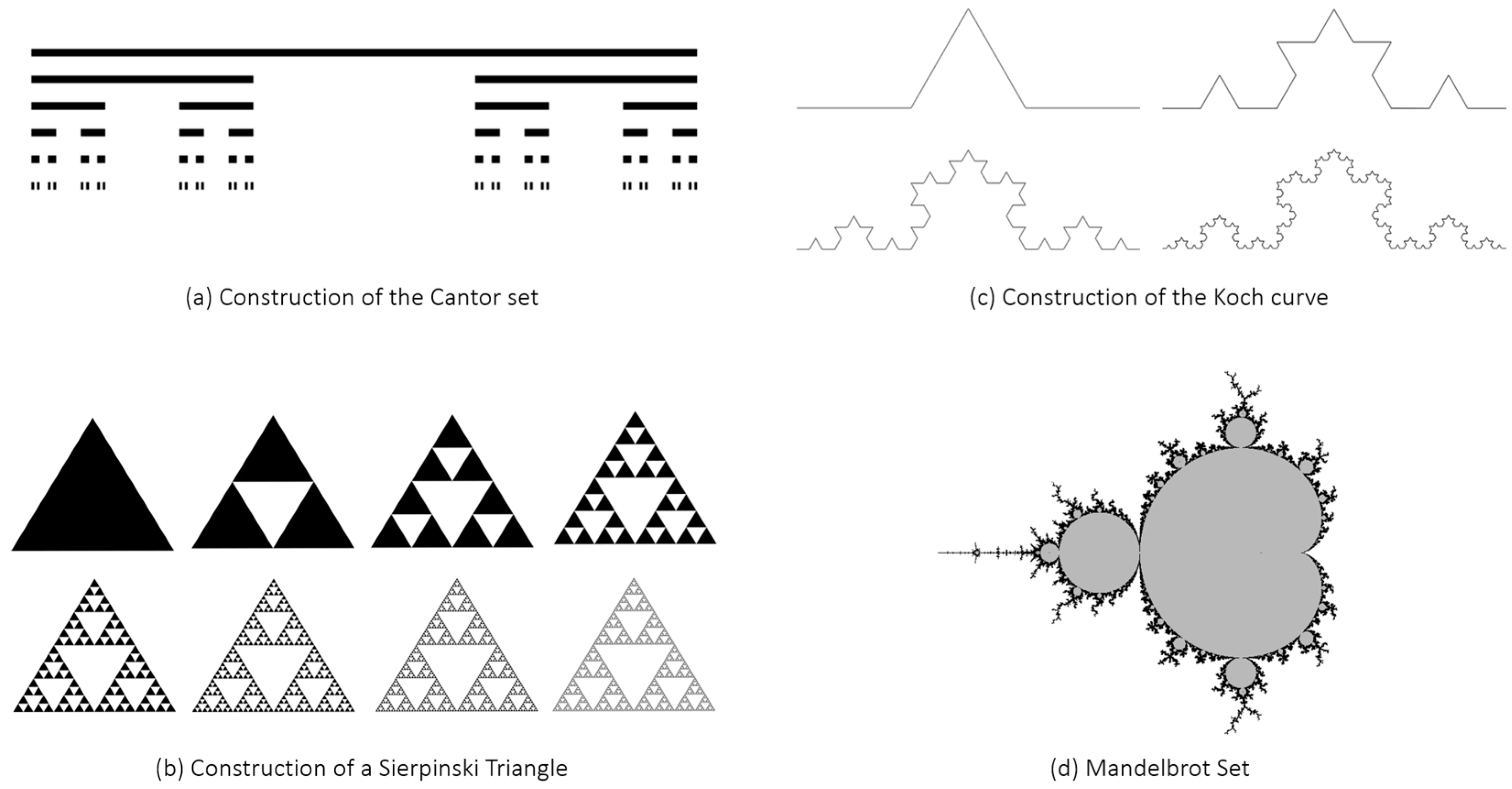
1. Introduction
- computer graphics and animation, to generate realistic and visually appealing natural landscapes, trees, clouds, and textures;
- data compression techniques, to reduce the size of digital files;
- image and signal processing, to extract features from images, detect patterns, and provide efficient methods for image compression and reconstruction;
- biology, to describe the growth of plants and the organization of neurons in the brain;
- antenna theory and metamaterials, to design compact/multiband antennas and innovative metasurfaces.
2. Fractal Antenna Elements


3. Fractal Reflectarray Antennas
3.1. Review of Existing Fractal Reflectarray Elements
- variable-size patches, in which the reflection phase is controlled by varying the patch size around its resonant size;
- fixed-size patches, in which the phase-tuning mechanism is based on the use of a variable-length coupled element, such as a line and/or slot, embedded in the same cell;
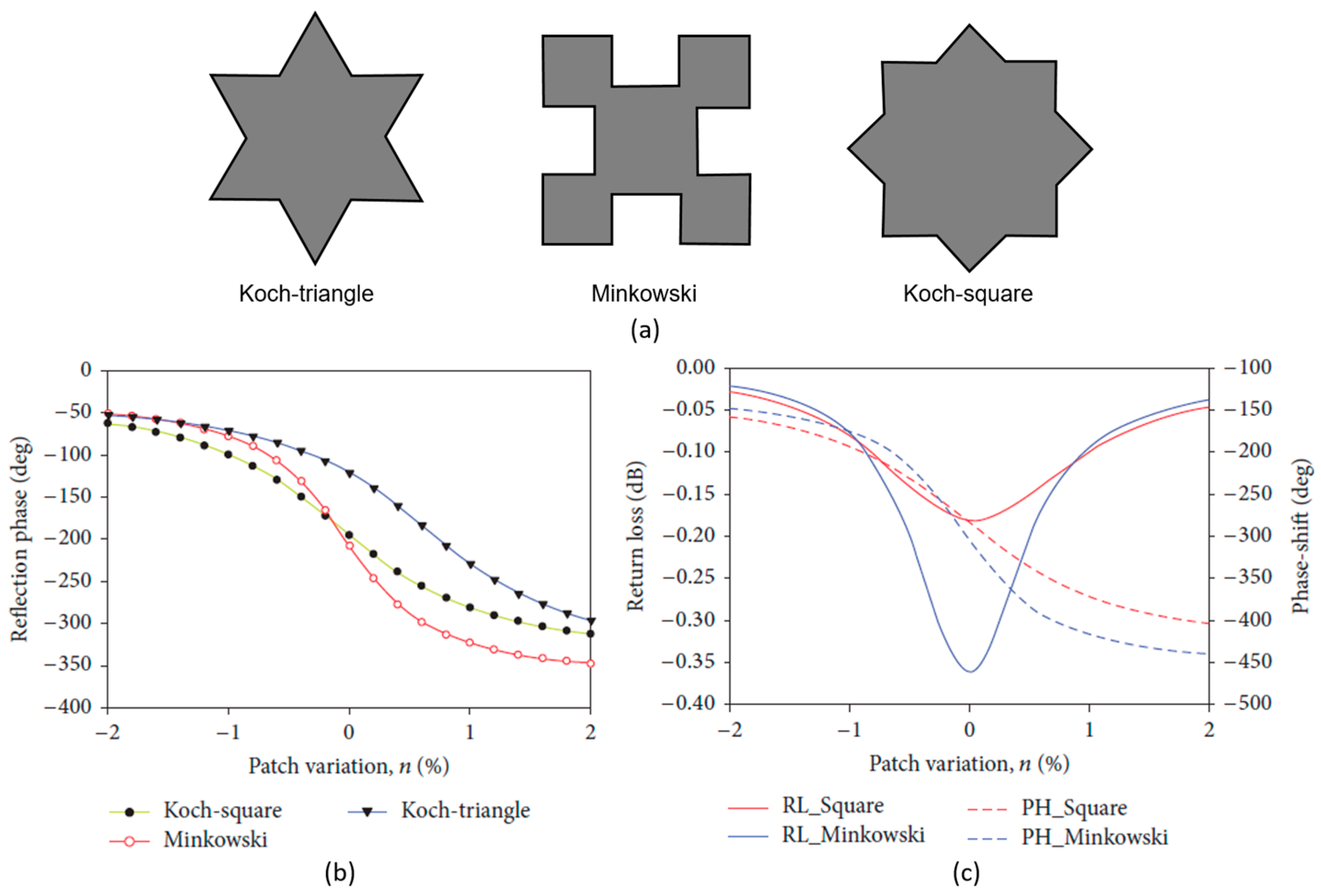
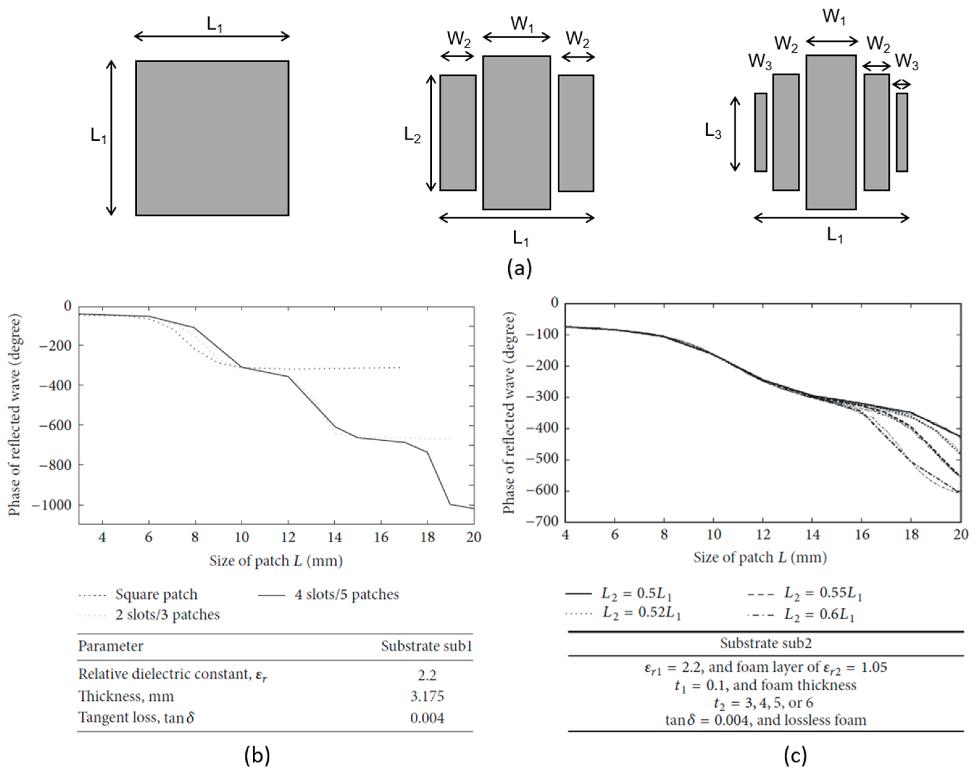
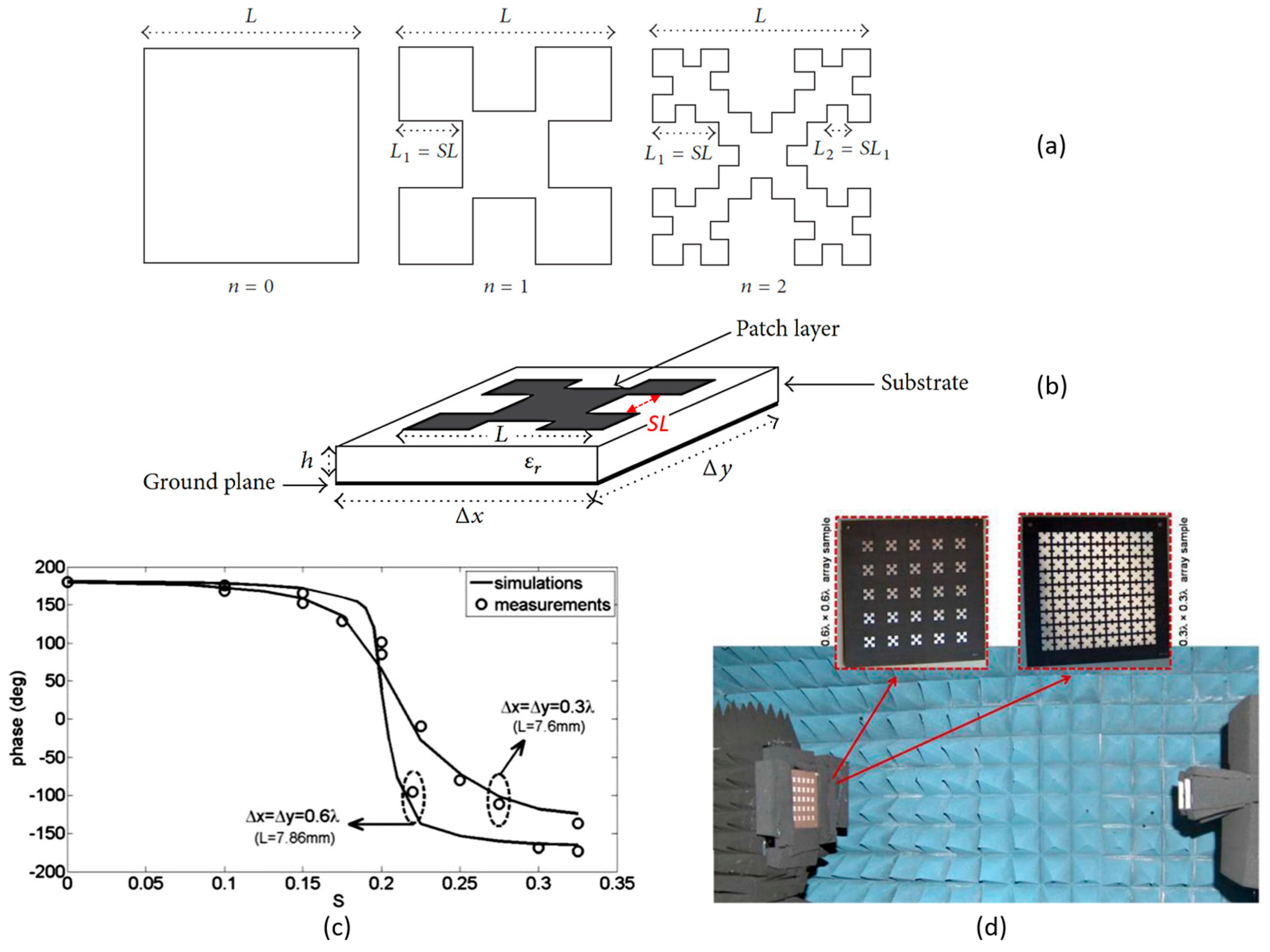
3.1.1. Variable-Size Fractal Patches
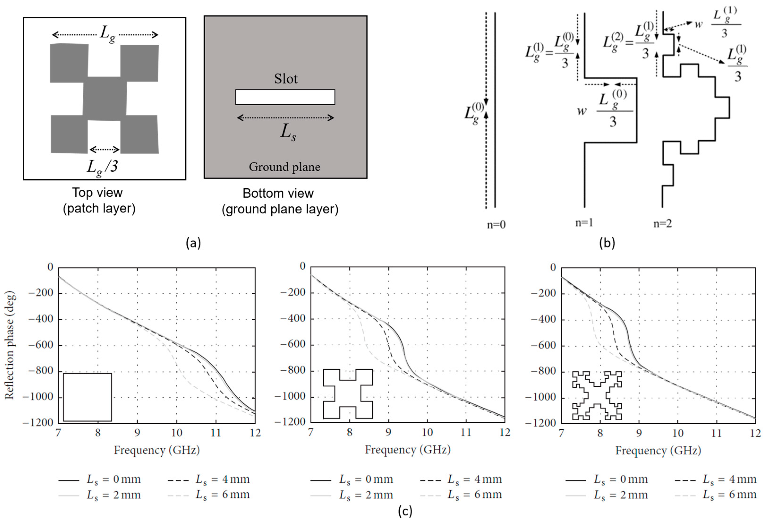
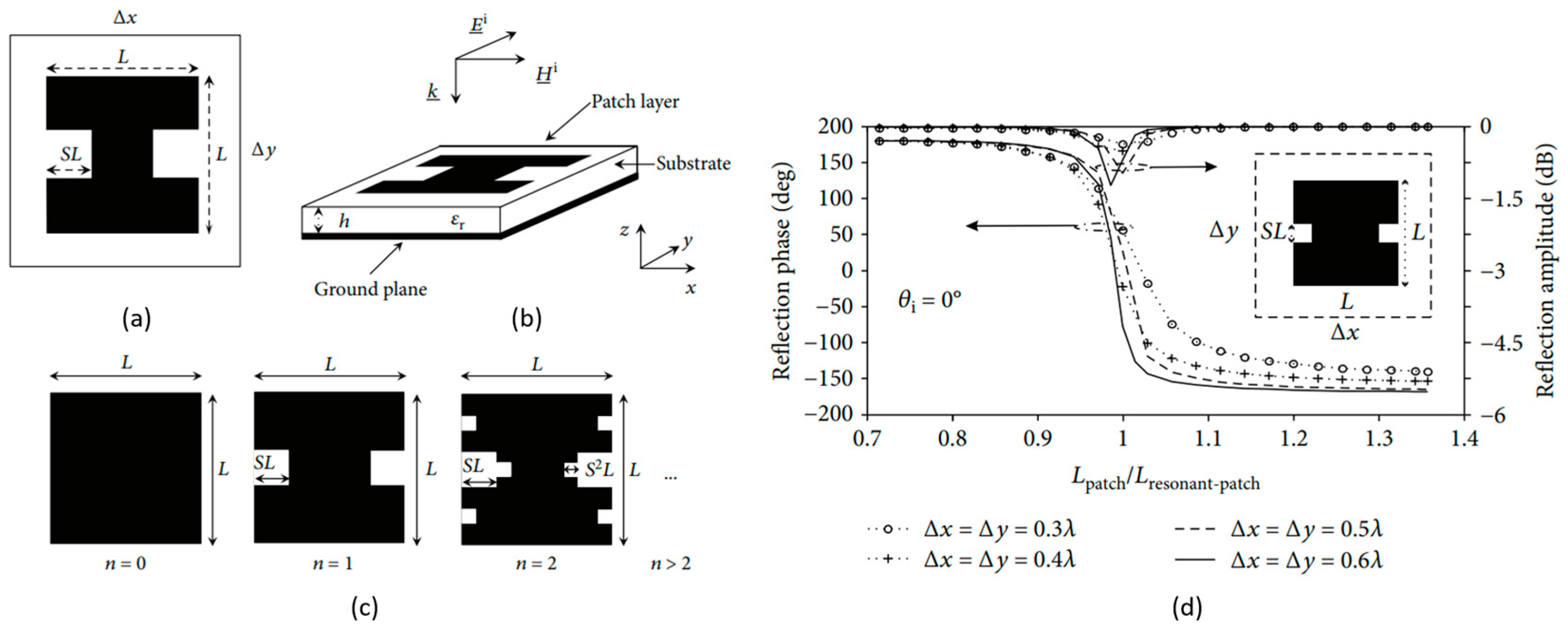
3.1.2. Fixed-Size Fractal Patches
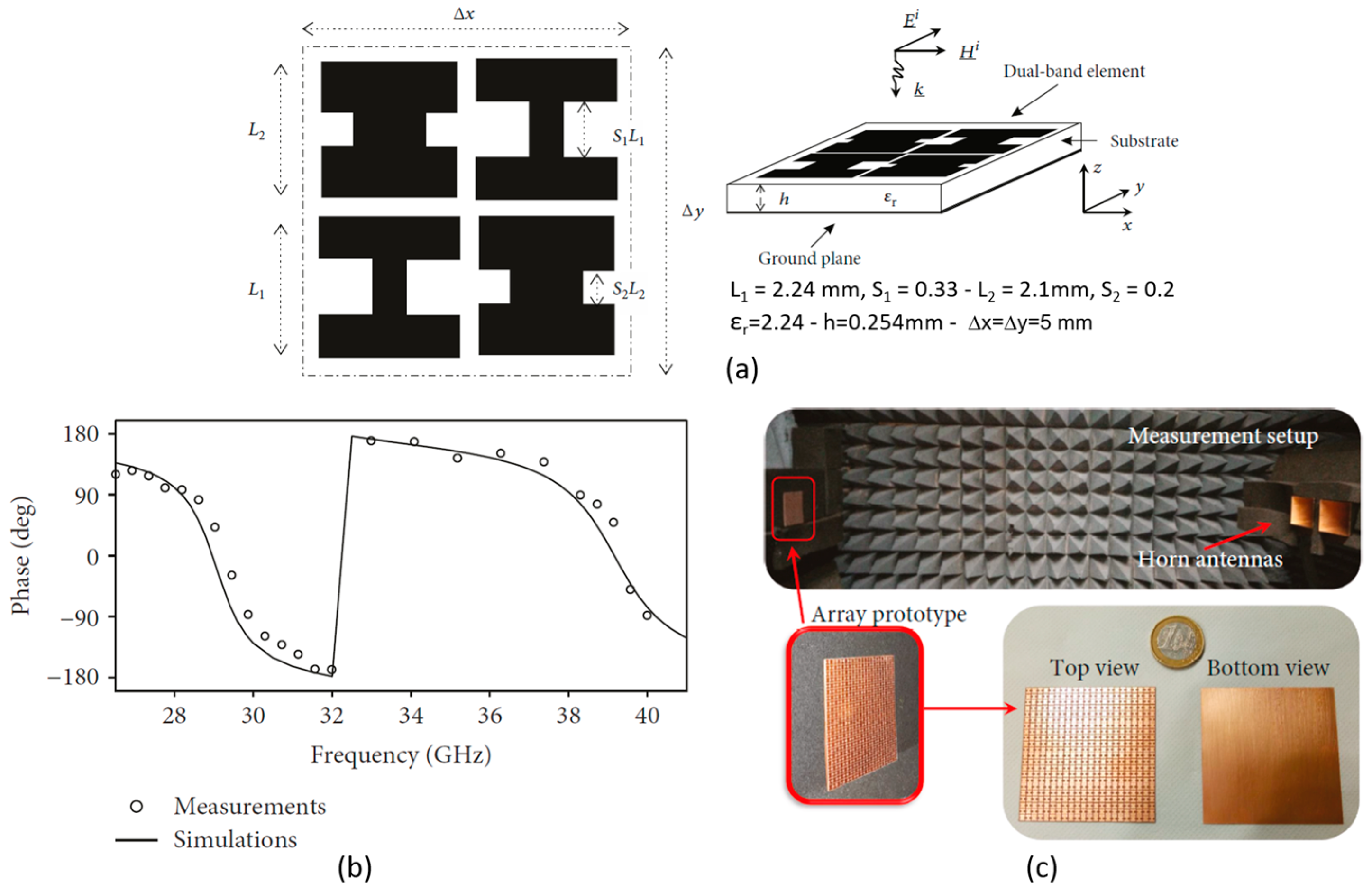
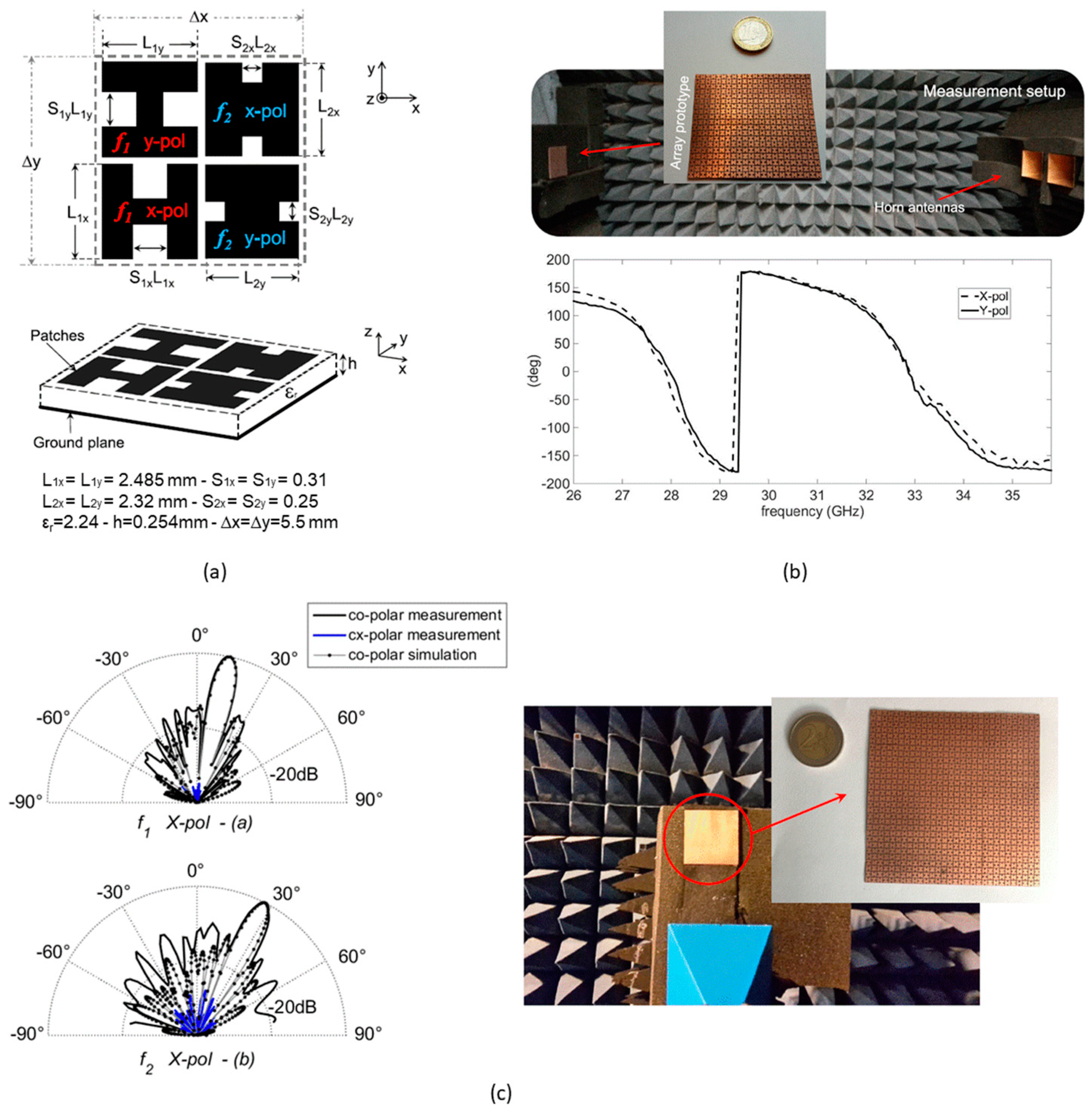
3.2. Fractal Reflectarray Elements with Multifunctional Operation
4. Fractal Metasurfaces
- sensitivity to the impinging wave incident angle which may lead to performance degradation or altered functionalities;
- fabrication challenges related to the precision and the costs of the adopted manufacturing process in realizing subwavelength elements.
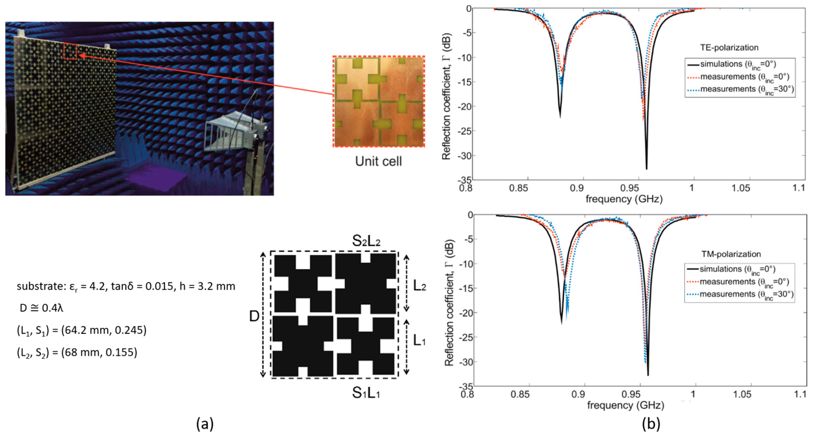
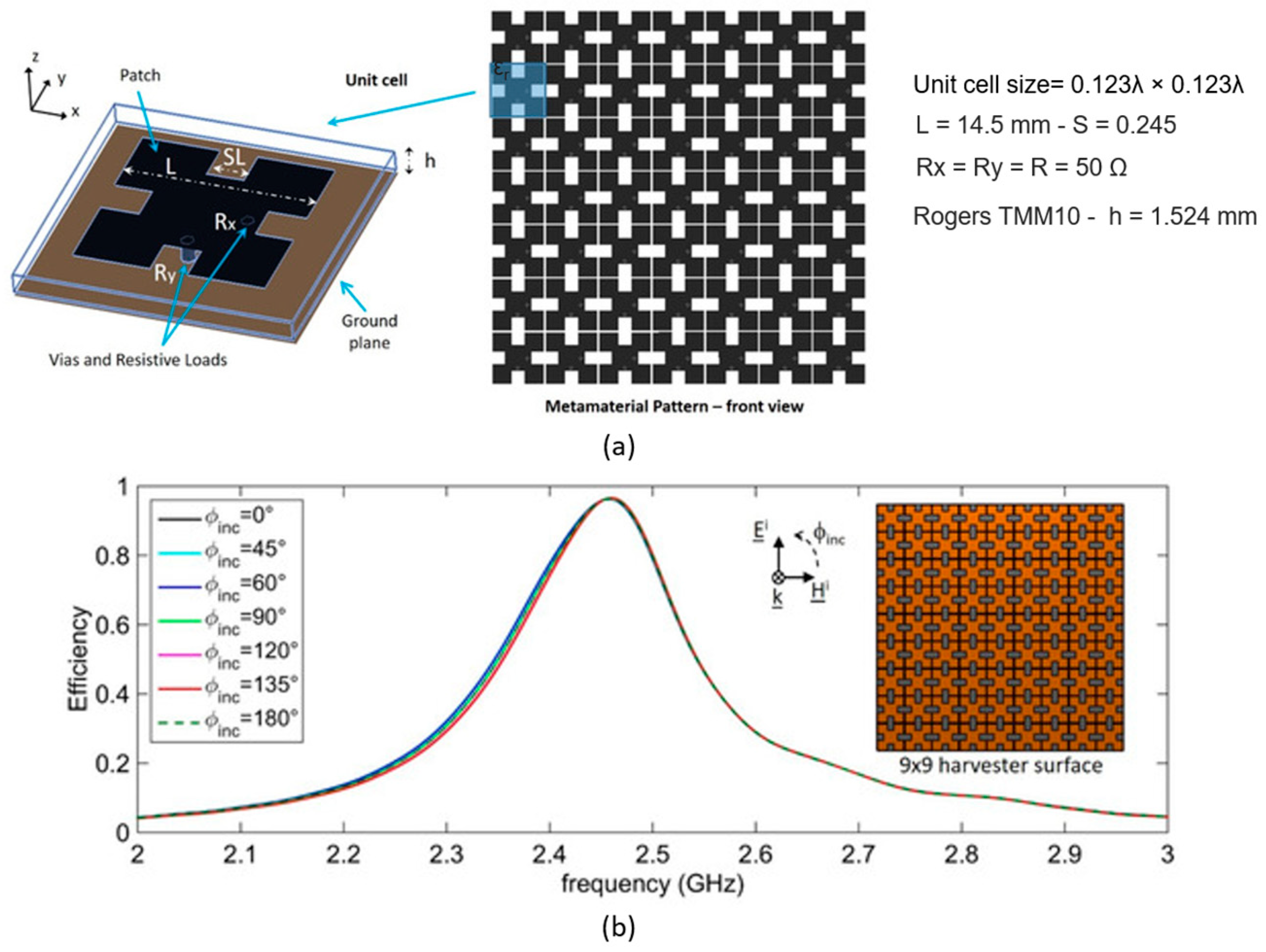
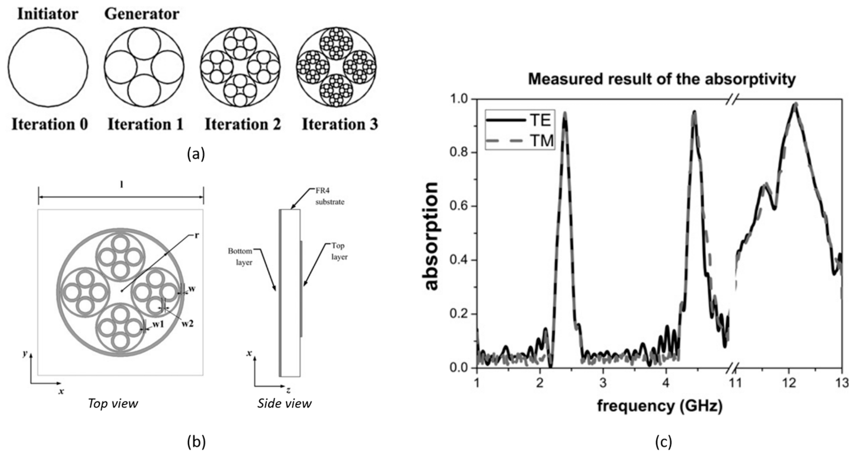
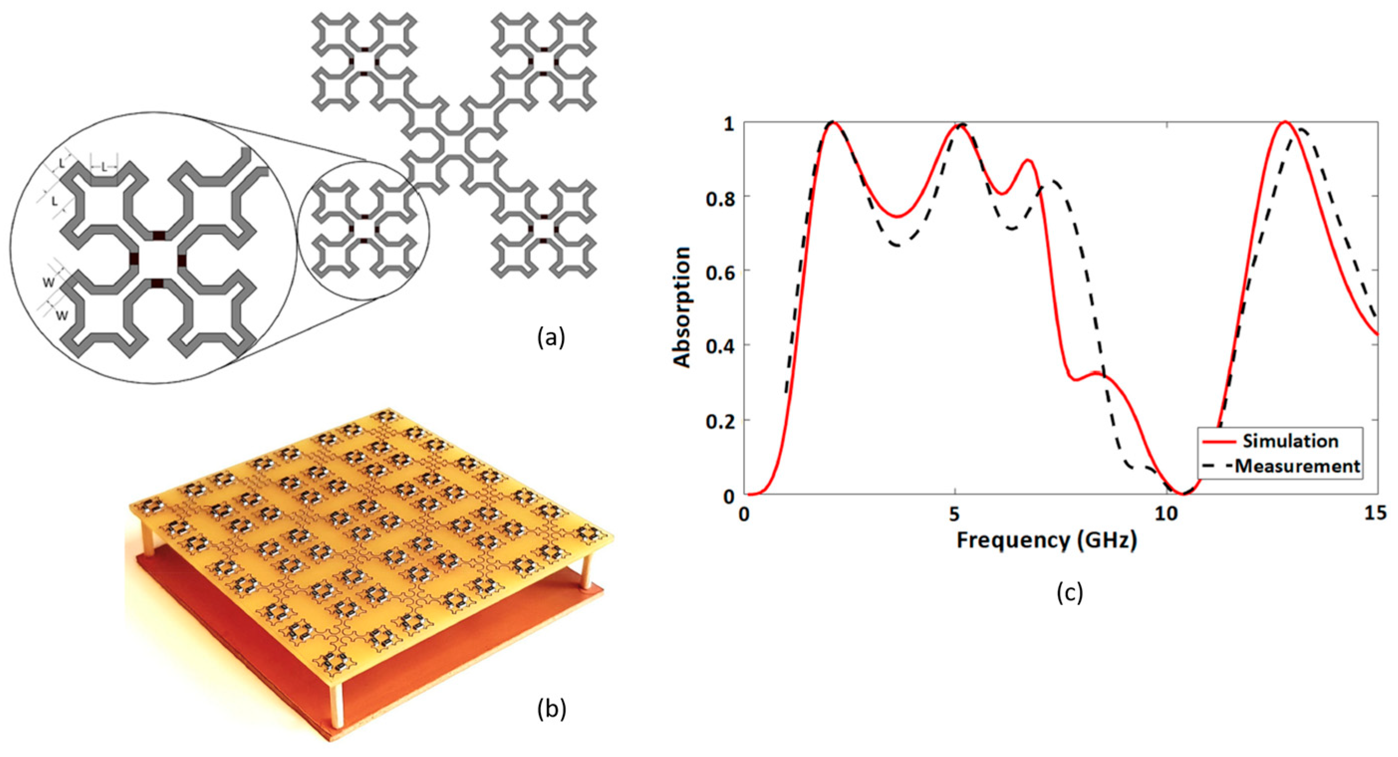
4.1. Fractal Metamaterial Absorbers
4.1.1. Impact of Fractals on the Electromagnetic Performance of Metamaterial Absorbers
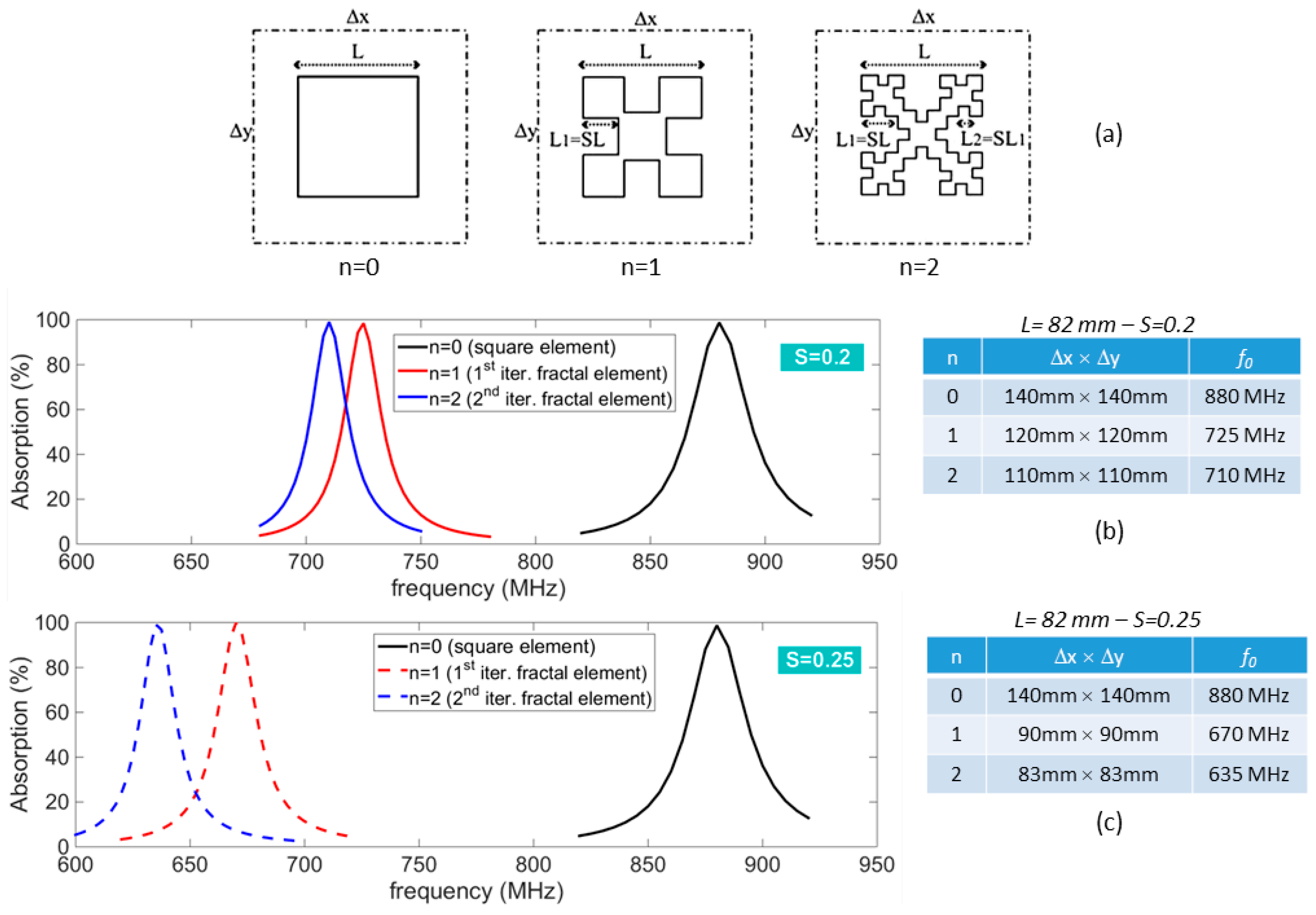
4.1.2. Examples of Fractal-Based MAs


4.2. Fractal Metamaterial Polarizers
4.3. Fractal Metamaterial in Antenna Applications

4.4. Future Developments of Fractal Metasurfaces
5. Conclusions
Author Contributions
Funding
Conflicts of Interest
References
- Mandelbrot, B.B. Fractals: Form Chance and Dimension; W.H. Freeman: San Francisco, CA, USA, 1977. [Google Scholar]
- Lauwerier, H. Fractals—Endless Repeated Geometrical Figures; Princeton University Press: Princeton, NJ, USA, 1991. [Google Scholar]
- Sierpinski, W. Sur une courbe dont tout point est un point de ramification. CR Acad. Sci. 1915, 160, 302–305. [Google Scholar]
- Julia, G. Memoire sur l’iteration des fonctions rationnelles. J. Pure Appl. Math. 1918, 1, 47–245. [Google Scholar]
- Fatou, P. Sur l’itération des fonctions transcendantes entières. Acta Math. 1926, 47, 337–370. [Google Scholar] [CrossRef]
- Mandelbrot, B.B. The Fractal Geometry of Nature; W.H. Freeman: New York, NY, USA, 1983. [Google Scholar]
- Mandelbrot, B.B. Fractal and Chaos: The Mandelbrot Set and Beyond; Springer: New York, NY, USA, 2004. [Google Scholar]
- Xinhuan, Y.; Chiochetti, J.; Papadopoulos, D.; Susman, L. Fractal Antenna Elements and Arrays. Appl. Microw. Wirel. 1999, 11, 34–46. [Google Scholar]
- Karmakar, A. Fractal antennas and arrays: A review and recent developments. Int. J. Microw. Wirel. Technol. 2021, 13, 173–197. [Google Scholar] [CrossRef]
- Li, S.J.; Cui, T.J.; Li, Y.B.; Zhang, C.; Li, R.Q.; Cao, X.Y.; Guo, Z.X. Fractal Metasurfaces: Multifunctional and Multiband Fractal Metasurface Based on Inter-Metamolecular Coupling Interaction. Adv. Theory Simul. 2019, 2, 1970030. [Google Scholar] [CrossRef]
- Bayatmaku, N.; Lotfi, P.; Azarmanesh, M.; Soltani, S. Design of Simple Multiband Patch Antenna for Mobile Communication Applications Using New E-Shape Fractal. IEEE Antennas Wirel. Propag. Lett. 2011, 10, 873–875. [Google Scholar] [CrossRef]
- Cohen, N. Fractal antenna applications in wireless telecommunications. In Proceedings of the Electronics Industries Forum of New England, Boston, MA, USA, 6–8 May 1997; pp. 43–49. [Google Scholar]
- Anwer, A.I.; Alibakhshikenari, M.; Elwi, T.A.; Virdee, B.S.; Kouhalvandi, L.; Hassain, Z.A.A.; Soruri, M.; Tokan, N.T.; Parchin, N.O.; See, C.H.; et al. Minkowski Based Microwave Resonator for Material Detection over Sub-6 GHz 5G Spectrum. In Proceedings of the 2023 2nd International Conference on 6G Networking (6GNet), Paris, France, 18–20 October 2023; pp. 1–4. [Google Scholar] [CrossRef]
- Obaid, S.M.; Elwi, T.A.; Ilyas, M. Fractal Minkowski-Shaped Resonator for Noninvasive Biomedical Measurements: Blood Glucose Test. Prog. Electromagn. Res. C 2021, 107, 143–156. [Google Scholar] [CrossRef]
- Abdulsattar, R.K.; Elwi, T.A.; Abdul Hassain, Z.A. A New Microwave Sensor Based on the Moore Fractal Structure to Detect Water Content in Crude Oil. Sensors 2021, 21, 7143. [Google Scholar] [CrossRef]
- Silva, C.P.N.; Araujo, J.A.I.; Coutinho, M.S.; Oliveira, M.R.T.; Llamas-Garro, I.; de Melo, M.T. Multi-band microwave sensor based on Hilbert’s fractal for dielectric solid material characterization. J. Electromagn. Waves Appl. 2021, 35, 848–860. [Google Scholar] [CrossRef]
- Cavalcanti Filho, P.H.B.; Araujo, J.A.I.; Oliveira, M.R.T.; de Melo, M.T.; Coutinho, M.S.; da Silva, L.M.; Llamas-Garro, I. Planar Sensor for Material Characterization Based on the Sierpinski Fractal Curve. J. Sens. 2020, 2020, 8830596. [Google Scholar] [CrossRef]
- Kim, Y.; Jaggard, D.L. The fractal random array. Proc. IEEE 1986, 74, 1278–1280. [Google Scholar] [CrossRef]
- Cohen, N. Fractal Antennas: Part I. Commun. Q. 1995, 9, 7–22. [Google Scholar]
- Cohen, N. Fractal Antennas: Part 2. Commun. Q. 1996, 6, 53–66. [Google Scholar]
- Fractal Antenna Systems Inc. Available online: https://www.fractenna.com/ (accessed on 27 January 2024).
- Puente, C.; Romeu, J.; Pous, R.; Garcia, X.; Benítez, F. Fractal Multiband Antenna Based on the Sierpinski Gasket. IEE Electron. Lett. 1996, 32, 1–2. [Google Scholar] [CrossRef]
- Anguera, J.; Borja, C.; Puente, C. Microstrip Fractal-Shaped Antennas: A Review. In Proceedings of the 2nd European Conference on Antennas and Propagation (EuCAP 2007), Edinburgh, UK, 11–16 November 2007; pp. 1–7. [Google Scholar] [CrossRef]
- Werner, D.H.; Ganguly, S. An overview of fractal antenna engineering research. IEEE Antennas Propag. Mag. 2003, 45, 38–57. [Google Scholar] [CrossRef]
- Puente, C.; Romeu, J.; Bartolemi, R.; Pous, R. Perturbation of the Sierpinski antenna to allocate operating bands. IEE Electron. Lett. 1996, 32, 2186–2188. [Google Scholar] [CrossRef]
- Puente, C.; Romeu, J.; Pous, R.; Cardama, A. On the behavior of the Sierpinski multiband fractal antenna. IEEE Trans. Antennas Propag. 1998, 46, 517–524. [Google Scholar] [CrossRef]
- Baliarda, C.P.; Romeu, J.; Cardama, A. The Koch monopole: A small fractal antenna. IEEE Trans. Antennas Propag. 2000, 48, 1773–1781. [Google Scholar] [CrossRef]
- Bakytbekov, A.; Maza, A.R.; Nafe, M.; Shamim, A. Fully inkjet printed wide band cantor fractal antenna for RF energy harvesting application. In Proceedings of the 11th European Conference on Antennas and Propagation (EUCAP), Paris, France, 19–24 March 2017; pp. 489–491. [Google Scholar] [CrossRef]
- Anguera, J.; Andújar, A.; Jayasinghe, J.; Chakravarthy, V.V.S.S.S.; Chowdary, P.S.R.; Pijoan, J.L.; Ali, T.; Cattani, C. Fractal Antennas: An Historical Perspective. Fractal Fract. 2020, 4, 3. [Google Scholar] [CrossRef]
- Anguera, J.; Puente, C.; Martínez, E.; Rozan, E. The fractal Hilbert monopole: A two-dimensional wire. Microw. Opt. Technol. Lett. 2003, 36, 102–104. [Google Scholar] [CrossRef]
- Anguera, J.; Andújar, A.; Benavente, S.; Jayasinghe, J.; Kahng, S. High-directivity microstrip antenna with Mandelbrot fractal boundary. IET Microw. Antennas Propag. 2018, 12, 569–575. [Google Scholar] [CrossRef]
- Borja, C.; Font, G.; Blanch, S.; Romeu, J. High directivity fractal boundary microstrip patch antenna. Electron. Lett. 2000, 36, 778–779. [Google Scholar] [CrossRef]
- Costanzo, S.; Venneri, F.; Di Massa, G.; Borgia, A.; Costanzo, A.; Raffo, A. Fractal Reflectarray Antennas: State of Art and New Opportunities. Int. J. Antennas Propag. 2016, 2016, 7165143. [Google Scholar] [CrossRef]
- Huang, J.; Encinar, J. Reflectarray Antennas; Wiley-IEEE Press: New York, NY, USA, 2008. [Google Scholar]
- Nayeri, P.; Yang, F.; Elsherbeni, A.Z. Reflectarray Antennas: Theory, Designs, and Applications; Wiley-IEEE Press: New York, NY, USA, 2018. [Google Scholar] [CrossRef]
- Costanzo, S.; Venneri, F.; Di Massa, G. Bandwidth enhancement of aperture-coupled reflectarrays. IEE Electron. Lett. 2006, 42, 1320–1322. [Google Scholar] [CrossRef]
- Venneri, F.; Costanzo, S.; Di Massa, G. Bandwidth behavior of closely spaced aperture-coupled reflectarrays. Int. J. Antennas Propag. 2012, 2012, 846017. [Google Scholar] [CrossRef]
- Venneri, F.; Costanzo, S.; Di Massa, G. Design and Validation of a Reconfigurable Single Varactor-Tuned Reflectarray. IEEE Trans. Antennas Propag. 2013, 61, 635–645. [Google Scholar] [CrossRef]
- Hum, S.V.; Perruisseau-Carrier, J. Reconfigurable reflectarrays and array lenses for dynamic antenna beam control: A review. IEEE Trans. Antennas Propag. 2014, 62, 183–198. [Google Scholar] [CrossRef]
- Nayeri, P.; Yang, F.; Elsherbeni, A.Z. Beam-scanning reflectarray antennas: A technical overview and state of the art. IEEE Antennas Propag. Mag. 2015, 57, 32–47. [Google Scholar] [CrossRef]
- Costanzo, S.; Venneri, F.; Raffo, A.; Di Massa, G. Dual-Layer Single-Varactor Driven Reflectarray Cell for Broad-Band Beam-Steering and Frequency Tunable Applications. IEEE Access 2018, 6, 71793–71800. [Google Scholar] [CrossRef]
- Costanzo, S.; Venneri, F.; Di Massa, G.; Borgia, A.; Raffo, A. Bandwidth performance of reconfigurable reflectarrays: State of art and future challenges. Radioengineering 2018, 27, 1–9. [Google Scholar] [CrossRef]
- Zubir, F.; Rahim, M.K.A. Simulated fractals shape for unit cell reflectarray. In Proceedings of the 2009 Asia Pacific Microwave Conference (APMC ’09), Singapore, 7–10 December 2009; pp. 583–586. [Google Scholar]
- Sayidmarie, K.H.; Bialkowski, M.E. Fractal unit cells of increased phasing range and low slopes for single-layer microstrip reflectarrays. IET Microw. Antennas Propag. 2011, 5, 1371–1379. [Google Scholar] [CrossRef]
- Oloumi, D.; Ebadi, S.; Kordzadeh, A.; Semnani, A.; Mousavi, P.; Gong, X. Miniaturized reflectarray unit cell using fractal shaped patch-slot configuration. IEEE Antennas Wirel. Propag. Lett. 2012, 11, 10–13. [Google Scholar] [CrossRef]
- Costanzo, S.; Venneri, F. Miniaturized Fractal Reflectarray Element Using Fixed-Size Patch. IEEE Antennas Wirel. Propag. Lett. 2014, 13, 1437–1440. [Google Scholar] [CrossRef]
- Costanzo, S.; Venneri, F.; Di Massa, G. Modified Minkowski fractal unit cell for reflectarrays with low sensitivity to mutual coupling effects. Int. J. Antennas Propag. 2019, 2019, 4890710. [Google Scholar] [CrossRef]
- Öztürk, E.; Saka, B. Multilayer Minkowski Reflectarray Antenna With Improved Phase Performance. IEEE Trans. Antennas Propag. 2021, 69, 8961–8966. [Google Scholar] [CrossRef]
- Costanzo, S.; Venneri, F.; Borgia, A.; Di Massa, G. A single-layer dual-band reflectarray cell for 5G communication systems. Int. J. Antennas Propag. 2019, 2019, 9479010. [Google Scholar] [CrossRef]
- Costanzo, S.; Venneri, F.; Borgia, A.; Di Massa, G. Dual-Band Dual-Linear Polarization Reflectarray for mmWaves/5G Applications. IEEE Access 2020, 8, 78183–78192. [Google Scholar] [CrossRef]
- Cohen, N. Radiative Transfer and Power Control with Fractal Metamaterial and Plasmonics. U.S. Patent 9,482,474-B2, 1 November 2016. Available online: https://ppubs.uspto.gov/dirsearch-public/print/downloadPdf/9482474 (accessed on 1 March 2024).
- Cohen, N.; Salkind, P. Enhanced Gain Antenna Systems Employing Fractal Metamaterials. U.S. Patent 11,268,771-B2, 8 March 2022. Available online: https://ppubs.uspto.gov/dirsearch-public/print/downloadPdf/11268771 (accessed on 1 March 2024).
- Venneri, F.; Costanzo, S.; Di Massa, G. Fractal-Shaped Metamaterial Absorbers for Multireflections Mitigation in the UHF Band. IEEE Antennas Wirel. Propag. Lett. 2018, 17, 255–258. [Google Scholar] [CrossRef]
- Venneri, F.; Costanzo, S.; Borgia, A. A Dual-Band Compact Metamaterial Absorber with Fractal Geometry. Electronics 2019, 8, 879. [Google Scholar] [CrossRef]
- Costanzo, S.; Venneri, F. Polarization-Insensitive Fractal Metamaterial Surface for Energy Harvesting in IoT Applications. Electronics 2020, 9, 959. [Google Scholar] [CrossRef]
- Jiang, H.; Xue, Z.; Li, W.; Ren, W. Multiband polarisation insensitive metamaterial absorber based on circular fractal structure. IET Microw. Antennas Propag. 2016, 10, 1141–1145. [Google Scholar] [CrossRef]
- Amiri, M.; Tofigh, F.; Shariati, N.; Lipman, J.; Abolhasan, M. Miniature tri-wideband Sierpinski–Minkowski fractals metamaterial perfect absorber. IET Microw. Antennas Propag. 2019, 13, 991–996. [Google Scholar] [CrossRef]
- Goyal, N.; Panwar, R. Minkowski inspired circular fractal metamaterial microwave absorber for multiband applications. Appl. Phys. A 2023, 129, 293. [Google Scholar] [CrossRef]
- Xu, H.X.; Wang, G.M.; Qi, M.Q.; Liang, J.G.; Gong, J.Q.; Xu, Z.M. Triple-band polarization-insensitive wide-angle ultra-miniature metamaterial transmission line absorber. Phys. Rev. B 2012, 86, 205104. [Google Scholar] [CrossRef]
- Landy, N.I.; Sajuyigbe, S.; Mock, J.J.; Smith, D.R.; Padilla, W.J. Perfect metamaterial absorber. Phys. Rev. Lett. 2008, 100, 207402. [Google Scholar] [CrossRef]
- Watts, C.M.; Liu, X.; Padilla, W.J. Metamaterial electromagnetic wave absorbers. Adv. Mater. 2012, 24, 98–120. [Google Scholar] [CrossRef] [PubMed]
- Abdulkarim, Y.I.; Mohanty, A.; Acharya, O.P.; Appasani, B.; Khan, M.S.; Mohapatra, S.K.; Muhammadsharif, F.F.; Dong, J. A Review on Metamaterial Absorbers: Microwave to Optical. Front. Phys. 2022, 10, 893791. [Google Scholar] [CrossRef]
- Liang, Y.; Lin, H.; Lin, S.; Wu, J.; Li, W.; Meng, F.; Yang, Y.; Huang, X.; Jia, B.; Kivshar, Y. Hybrid anisotropic plasmonic metasurfaces with multiple resonances of focused light beams. Nano Lett. 2021, 21, 8917–8923. [Google Scholar] [CrossRef]
- Stewart, J.W.; Nebabu, T.; Mikkelsen, M.H. Control of Nanoscale Heat Generation with Lithography-Free Metasurface Absorbers. Nano Lett. 2022, 22, 5151–5157. [Google Scholar] [CrossRef]
- Kim, S.; Vyas, R.; Bito, J.; Niotaki, K.; Collado, A.; Georgiadis, A.; Tentzeris, M.M. Ambient RF Energy-Harvesting Technologies for Self-Sustainable Standalone Wireless Sensor Platforms. Proc. IEEE 2014, 102, 1649–1666. [Google Scholar] [CrossRef]
- Ramahi, O.M.; Almoneef, T.S.; AlShareef, M.; Boybay, M.S. Metamaterial particles for electromagnetic energy harvesting. Appl. Phys. Lett. 2012, 101, 173903. [Google Scholar] [CrossRef]
- Amer, A.A.G.; Sapuan, S.Z.; Nasimuddin, N.; Alphones, A.; Zinal, N.B. A Comprehensive Review of Metasurface Structures Suitable for RF Energy Harvesting. IEEE Access 2020, 8, 76433–76452. [Google Scholar] [CrossRef]
- Sherazi, H.H.R.; Zorbas, D.; O’Flynn, B. A Comprehensive Survey on RF Energy Harvesting: Applications and Performance Determinants. Sensors 2022, 22, 2990. [Google Scholar] [CrossRef] [PubMed]
- Góra, P.; Łopato, P. Metamaterials’ Application in Sustainable Technologies and an Introduction to Their Influence on Energy Harvesting Devices. Appl. Sci. 2023, 13, 7742. [Google Scholar] [CrossRef]
- Yogesh, N.; Ouyang, Z. Metamaterial frequency selective surfaces as polarizers. In Handbook of Metamaterial-Derived Frequency Selective Surfaces. Metamaterials Science and Technology; Narayan, S., Kesavan, A., Eds.; Springer: Singapore, 2022; Volume 3, pp. 285–311. [Google Scholar]
- Xu, H.X.; Wang, G.M.; Qi, M.Q.; Cai, T.; Cui, T.J. Compact dual-band circular polarizer using twisted Hilbert-shaped chiral metamaterial. Opt. Express 2013, 21, 24912–24921. [Google Scholar] [CrossRef] [PubMed]
- Bilal, R.M.H.; Baqir, M.A.; Choudhury, P.K.; Ali, M.M.; Rahim, A.A. On the specially designed fractal metasurface-based dual-polarization converter in the THz regime. Results Phys. 2020, 19, 103358. [Google Scholar] [CrossRef]
- Palandoken, M.; Grede, A.; Henke, H. Broadband microstrip antenna with left-handed metamaterials. IEEE Trans. Antennas Propag. 2009, 57, 331–338. [Google Scholar] [CrossRef]
- Kossiavas, C.; Zeitler, A.; Clementi, G.; Migliaccio, C.; Staraj, R.; Kossiavas, G. X-Band circularly polarized antenna gain enhancement with metamaterials. Microw. Opt. Technol. Lett. 2011, 53, 1911–1915. [Google Scholar] [CrossRef]
- Dong, Y.D.; Toyao, H.; Itoh, T. Compact circularly-polarized patch antenna loaded with metamaterial structures. IEEE Trans. Antennas Propag. 2011, 59, 4329–4333. [Google Scholar] [CrossRef]
- de Fátima Linhares de Vasconcelos, C.; de Albuquerque, M.R.M.L.; da Silva, S.G.; de Ribamar Silva Oliveira, J.; d’Assunção, A.G. Full-wave analysis of annular ring microstrip antenna on metamaterial. IEEE Trans. Magn. 2011, 47, 1110–1113. [Google Scholar] [CrossRef]
- Buell, K.; Mosallaei, H.; Sarabandi, K. A substrate for small patch antennas providing tunable miniaturization factors. IEEE Trans. Microw. Theory Tech. 2006, 54, 135–146. [Google Scholar] [CrossRef]
- Chillakuru, S.R.; Muraleedharan, N.; Upadhayay, M.D. Triangular metamaterial loaded antenna for low RCS stealth application. In Proceedings of the 2022 International Conference for Advancement in Technology (ICONAT), Goa, India, 21–22 January 2022; pp. 1–7. [Google Scholar]
- Xu, H.X.; Wang, G.M.; Qi, M.Q. Hilbert-shaped magnetic waveguided metamaterials for electromagnetic coupling reduction of microstrip antenna array. IEEE Trans. Magn. 2013, 49, 1526–1529. [Google Scholar] [CrossRef]
- Assimonis, S.D.; Yioultsis, T.V.; Antonopoulos, C.S. Computational investigation and design of planar EBG structures for coupling reduction in antenna applications. IEEE Trans. Magn. 2012, 48, 771–774. [Google Scholar] [CrossRef]
- Xu, H.X.; Wang, G.M.; Liang, J.G.; Qi, M.Q.; Gao, X. Compact circularly polarized antennas combining meta-surfaces and strong space-filling meta-resonators. IEEE Trans. Antennas Propag. 2013, 61, 3442–3450. [Google Scholar] [CrossRef]
- Liu, G.; Xu, L.; Wu, Z. Miniaturized Circularly Polarized Microstrip RFID Antenna Using Fractal Metamaterial. Int. J. Antennas Propag. 2013, 2013, 781357. [Google Scholar] [CrossRef]
- Xu, H.X.; Wang, G.M.; Qi, M.Q.; Cai, T. Compact fractal left-handed structures for improved cross-polarization radiation pattern. IEEE Trans. Antennas Propag. 2014, 62, 546–554. [Google Scholar] [CrossRef]
- Xu, H.X.; Wang, G.M.; Qi, M.Q.; Zeng, H.Y. Ultra-small single negative electric metamaterials for electromagnetic coupling reduction of microstrip antenna array. Opt. Exp. 2012, 20, 21968–21976. [Google Scholar] [CrossRef] [PubMed]
- Cai, T.; Wang, G.M.; Zhang, X.F.; Shi, J.P. Low-profile compact circularly-polarized antenna based on fractal metasurface and fractal resonator. IEEE Antennas Wirel. Propag. Lett. 2015, 14, 1072–1076. [Google Scholar] [CrossRef]
- Tang, W.; Chen, J.; Cui, T.J. Metamaterial lenses and their applications at microwave frequencies. Adv. Photonics Res. 2021, 2, 2100001. [Google Scholar] [CrossRef]
- Lee, J.; Kim, H.; Oh, J. Large-Aperture Metamaterial Lens Antenna for Multi-Layer MIMO Transmission for 6G. IEEE Access 2022, 10, 20486–20495. [Google Scholar] [CrossRef]
- Xu, H.X.; Wang, G.M.; Qi, M.Q.; Li, L.; Cui, T. Three-Dimensional Super Lens Composed of Fractal Left-Handed Materials. Adv. Opt. Mater. 2013, 1, 495–502. [Google Scholar] [CrossRef]
- Xu, H.X.; Wang, G.M.; Tao, Z.; Cai, T. High-Directivity Emissions with Flexible Beam Numbers and Beam Directions Using Gradient-Refractive-Index Fractal Metamaterial. Sci. Rep. 2014, 4, 5744. [Google Scholar] [CrossRef] [PubMed]
- Xu, H.X.; Wang, G.M.; Tao, Z.; Cai, T. An Octave-Bandwidth Half Maxwell Fish-Eye Lens Antenna Using Three-Dimensional Gradient-Index Fractal Metamaterials. IEEE Trans. Antennas Propag. 2014, 62, 4823–4828. [Google Scholar] [CrossRef]
- Cohen, N.; Okoro, O.; Salkind, P. Wideband Electromagnetic Cloaking Systems. U.S. Patent 10,027,033, 17 July 2018. Available online: https://ppubs.uspto.gov/dirsearch-public/print/downloadPdf/10027033 (accessed on 6 March 2024).
- Wu, R.; Dong, J.; Wang, M. Wearable Polarization Conversion Metasurface MIMO Antenna for Biomedical Applications in 5 GHz WBAN. Biosensors 2023, 13, 73. [Google Scholar] [CrossRef]
- Althuwayb, A.A.; Alibakhshikenari, M.; Virdee, B.S.; Rashid, N.; Kaaniche, K.; Ben Atitallah, A.; Armghan, A.; Elhamrawy, O.I.; See, C.H.; Falcone, F. Metasurface-Inspired Flexible Wearable MIMO Antenna Array for Wireless Body Area Network Applications and Biomedical Telemetry Devices. IEEE Access 2013, 11, 1039–1056. [Google Scholar] [CrossRef]
- Ozpinar, H.; Aksimsek, S. Fractal interwoven resonator based penta-band metamaterial absorbers for THz sensing and imaging. Sci. Rep. 2022, 12, 19758. [Google Scholar] [CrossRef] [PubMed]
- Zhang, W.; Lin, J.; Yuan, Z.; Lin, Y.; Shang, W.; Chin, L.K.; Zhang, M. Terahertz Metamaterials for Biosensing Applications: A Review. Biosensors 2024, 14, 3. [Google Scholar] [CrossRef]
- Buonanno, G.; Costanzo, S.; Solimene, R. Broadband statistically designed thinned-binned array antennas. IEEE Trans. Antennas Propag. 2023, 71, 2454–2466. [Google Scholar] [CrossRef]
- Buonanno, G.; Solimene, R. Global characterization of linear statistically thinned antenna arrays. IEEE Access 2021, 9, 119629–119640. [Google Scholar] [CrossRef]


Disclaimer/Publisher’s Note: The statements, opinions and data contained in all publications are solely those of the individual author(s) and contributor(s) and not of MDPI and/or the editor(s). MDPI and/or the editor(s) disclaim responsibility for any injury to people or property resulting from any ideas, methods, instructions or products referred to in the content. |
© 2024 by the authors. Licensee MDPI, Basel, Switzerland. This article is an open access article distributed under the terms and conditions of the Creative Commons Attribution (CC BY) license (https://creativecommons.org/licenses/by/4.0/).
Share and Cite
Venneri, F.; Costanzo, S.; Borgia, A. Fractal Metasurfaces and Antennas: An Overview for Advanced Applications in Wireless Communications. Appl. Sci. 2024, 14, 2843. https://doi.org/10.3390/app14072843
Venneri F, Costanzo S, Borgia A. Fractal Metasurfaces and Antennas: An Overview for Advanced Applications in Wireless Communications. Applied Sciences. 2024; 14(7):2843. https://doi.org/10.3390/app14072843
Chicago/Turabian StyleVenneri, Francesca, Sandra Costanzo, and Antonio Borgia. 2024. "Fractal Metasurfaces and Antennas: An Overview for Advanced Applications in Wireless Communications" Applied Sciences 14, no. 7: 2843. https://doi.org/10.3390/app14072843
APA StyleVenneri, F., Costanzo, S., & Borgia, A. (2024). Fractal Metasurfaces and Antennas: An Overview for Advanced Applications in Wireless Communications. Applied Sciences, 14(7), 2843. https://doi.org/10.3390/app14072843