Abstract
Triangular screw configuration (TSC) fixation is widely used in clinics for femoral neck fractures, and the appropriate positions of TSC fixation have not been fully described in the literature. This study investigated the optimal fixation of femoral neck fractures with TSC fixation under nonstandard Pauwels angles to determine the ideal position. To determine the optimal fracture line angle and cannulated screw positions, the Pauwels angle and Rotation and Translate variables were parametrically defined in the fracture line and cannulated screw positions. Considering the equivalent stresses on the fracture surfaces, the effectiveness values of the Rotation and Translate 1, 2 and 3 variables are weak, whereas the effectiveness value of the Pauwels angle is high. Considering the equivalent stress on the screws and that the variable value of Translates 1, 2 and 3 is 7 mm, it can be seen that the reverse triangulation configuration is better, and the Pauwels angle is approximately 54°. Among the parameters examined in the study, Pauwels angle was found to have the highest level of effectiveness on femoral neck fracture surfaces and screws. The findings in this study provide a solid basis for future research; however, further clinical research is warranted.
1. Introduction
Skeletal system traumas are among the most complex and demanding issues in the medical field. Among these traumas, femoral neck fractures (FNFs), especially those occurring in the femur region, constitute a significant group that leads to serious health problems in the aging population. FNFs are fractures located between the femoral head and trochanteric region and typically result from relatively low-energy traumas such as falls. Such fractures are commonly observed in elderly individuals, particularly in conjunction with decreased bone density. There are several risk factors for FNFs, including female sex, low bone density, and reduced mobility [1]. Pauwels classification is generally used in the treatment and management of FNFs [2]. Pauwels fracture types were determined as I, II, III and corresponding angles as “<30°”, “30–50°” and >50°, respectively [3]. An increase in the Pauwels angle leads to an increase in the vertical fracture slip surface, and consequently, to higher stresses in the fracture site [4,5]. Chantarapanich et al. [6] observed that in the stabilization of FNFs with TSC and inverted TSC, the equivalent stress values on the screws increased with the increase in the Pauwels angle and an increase in the amount of strain on the fracture surfaces. In a similar study, Wang et al. [7] observed that the equivalent stresses on the proximal femoral neck and the displacement of the screws increased as the Pauwel angle increased from 50 to 70 degrees. In the clinical setting, fixation methods such as TSC fixation, dynamic hip screw (DHS) fixation, and proximal femoral nail antirotation (PFNA) are generally used for FNFs [8,9,10]. In new generation fixation methods, different methods such as functionally graded material are used to reduce the stress shielding effect between the plate, screw, etc., and the bone [11]. Biomechanical study data on screw fixation in various positions in the femoral neck regions, the angle and direction in which the screws should be placed and how far they should be placed, and their optimization are limited. The aim of this study was to determine the optimal positions of the screws used in TSC systems to ensure optimal fixation of FNFs under Pauwels angles with defined limits. In the methodology determined for this purpose, the Pauwels angle and the rotational and translational movements of the screws used in TSC systems were determined parametrically. With these three parameters, the optimal conditions for the stabilization of FNFs were obtained according to the von Mises equivalent stress data on the screw and at the fracture site.
This comprehensive exploration into the biomechanics of FNFs treated with proximal femoral nails utilized a sophisticated computational methodology finite element analysis (FEA). FEA is a numerical method used for predicting how a product reacts to real-world forces, vibration, heat, fluid flow, and other physical effects. In orthopedics, it provides insights into complex biomechanical behavior that is challenging to understand through in vitro experiments or clinical studies alone [12].
2. Materials and Methods
In FNFs, many methods are used for the treatment and integration of fracture lines. The general aim of these methods is to adjust the stability and rigidity of the fracture line in a short time and to produce the most ideal solution for the patient. In this study, the Pauwels classification was used for FNFs. The fracture lines created with this classification were fixed with three cannulated screws to ensure the integrity of the fracture line. To determine the optimal fracture line angle and cannulated screw positions, some variables were parametrically defined at the fracture line and the positions of the cannulated screws.
2.1. Geometric and Parametric Modeling of FNF Types and Cannulated Screws
In this study, the femur bone of a healthy woman was examined, and CT data were obtained. The undamaged CT data of the patient were obtained from the archive of the Afyonkarahisar University of Health Sciences. Radiographic images were obtained with a Siemens Sensation 40 CT (Siemens AG, Munich, Germany), and the imaging values of the device were determined to be 120 kV and 65 mAs. In addition, radiographic images were obtained at 512 × 512 pixel resolution. In CT scanning, 665 Dicom format radiographic images were obtained. The slice thickness of the image data was determined to be 1 mm, and the pixel size was determined to be 0.6 mm.
Radiographic images were processed in the medical image processing software Mimics (Materials, Leuven, Belgium), and bone tissues were separated from other tissues. The mesh optimization of the femur bone obtained with an “.stl” extension was performed in Materials Magics 6 program and transferred to Geomagic Design X (3D Systems Inc., Rock Hill, SC, USA) and the mesh surfaces were converted into Non Uniform Rational Basis Splines (NURBS) surface form. Thanks to the NURBS surface form, the desired part addition or removal operations on the femur bone were performed on the ANSYS Workbench 2021 R1 (Ansys Inc., Canonsburg, PA, USA) program. A straight neck fracture was created on the proximal femur, and this fracture line was fixed with three cannulated screws. This system was optimized within certain parameters. These parameters were determined as Pauwels angle (Figure 1c), the angle of the three cannulated screws with the positive x-axis (Rotation, Figure 1b) and the distance of the cannulated screws from the origin (Translate, Figure 1b).
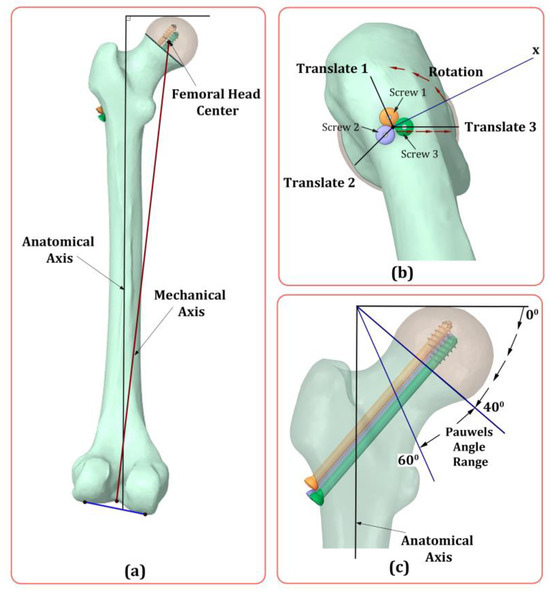
Figure 1.
Geometric and parametric modeling of the TSC system used in FNFs. Determination of anatomical and mechanical axis (a), rotational and translational movements of the screws (b), and Pauwels angle (c).
2.2. Material Properties, Loading, and Boundary Conditions
FNFs with three cannulated screws with similar properties were analyzed by the finite element method under specified boundary conditions. All system parts fixed with cannulated screws are defined as homogeneous, isotropic, and linear elastic material. The cannulated screws are made of Ti6Al4V material. The yield strength of the Ti6Al4V material is known to be 885 MPa [13]. The mechanical properties of the cannulated screw and other parts of the system are shown in Table 1 [14].

Table 1.
Mechanical properties of Cannulated Screws and Femur bone components.
The density value and modulus of elasticity of the femur bone fragments were generated from the HU value of the bone. The HU value is proportional to the absorbed portion of the X-rays sent to the bone from the tomography device used in the medical sector and is also a dimensionless value. The apparent density () and elasticity modulus () values were obtained by substituting the HU values of the femur bone fragments in Equation (1) [15]:
The coefficients a, b, and c for and are calibration parameters. All parts of the FNF system assembled with cannulated screws were transferred to the ANSYS finite element analysis program, where the interaction of the parts with each other was ensured. The mesh structures of the parts consist of tetrahedral elements with 4 nodes. All femur bone parts have a mesh size of 2 mm, cannulated screws have a mesh size of 1 mm and the mesh size between the fracture site surfaces was taken as 0.7 mm (Figure 2b). In total, the modeled system consists of 1,498,882 nodes and 1,019,038 elements.
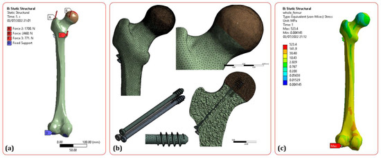
Figure 2.
Loading conditions (a), meshing (b) and result of FEM analysis (c).
During the finite element analysis, the condyle part of the distal femur was held, and the distal movement of the bone was prevented (Figure 2a). During the analysis performed by taking into account the biomechanical studies of the lower extremities, the boundary conditions of the stance position from the gait phases of the person were applied. Three forces were applied on the proximal femur. These were 2460 N force applied to the femoral head, 1700 N force applied by the abductor muscle and 771 N force applied by the iliopsoas muscle [16] (Figure 2a). The coefficients of friction were 0.46 [17] between the fracture surfaces of the femoral neck, 0.23 [18] between the PFN fragments, and 0.3 [19] between the femur bone fragments and PFN.
2.3. Optimization of Fracture Line and Cannulated Screw Positions
Cannulated screws are widely used for the internal fixation of FNFs. During this use, certain parameters effectively affect the stress distribution in the fracture line, which determines the healing process. In this study, a number of parameters were determined, and the most favorable conditions for the joint were determined (Figure 1b,c). These parameters are shown in Table 2.
Table 2.
Input parameters used in optimization [3,6].
These parameters were determined as input parameters in the response surface optimization (RSO) and goal driven optimization (GDO) modules within the ANSYS software. The von Mises equivalent stress values on the femur fracture site and on the screws were considered as output parameters. RSO is a method that analyzes the response affected by different parameters and transforms it into an optimized form [20]. The GDO method is based on the use of an algorithm that examines the interaction of multiple input and output parameters and provides the most appropriate input values according to the desired output values [21]. A second order polynomial model was chosen for the response surface. Due to the large number of input and output parameters, mathematical forms are needed to build many response surface models. If there is a curvature in the response surface graphs, the form specified in Equation (3) is used.
In this equation, is the response variable, is the unknown regression parameters, is the process variables , and is the error term.
3. Results
In this study, three cannulated screws were used for the stability and rigidity of FNFs. The positions of the fracture line (Pauwels angle) and cannulated screws (Rotation, Translate 1, Translate 2 and Translate 3) were determined as input parameters. Equivalent von Mises stress values on the fracture line surface and on each screw were determined as output parameters. In this study, first, a static analysis of the system (Figure 2c) was carried out by taking the average values of the input parameters (Table 2). Afterwards, the graphs of the desired output parameter values were analyzed, and the appropriate input parameters were selected according to the minimum equivalent stress values at the screw and fracture site. In this study, the importance of the Pauwels angle input parameter is slightly more prominent than that of the others. Figure 3 shows the behavior of the input parameters according to the equivalent stress values formed on the fractured surfaces with 3D graphs.
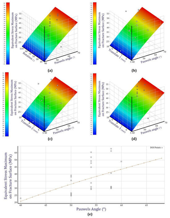
Figure 3.
Effects of Pauwels Angle Rotation (a), Pauwels Angle Translate 1 (b), Pauwels Angle Translate 2 (c), Pauwels Angle Translate 3 (d) and Pauwels Angle (e) parameters on the fracture surface.
The effects of the Input parameters Rotation and Translate 1, 2, and 3 on the stresses at the fracture surfaces are weak. On the other hand, the effect of the Pauwels angle on the stress values on the fracture surfaces is significant (Figure 3). When the effectiveness values of the input parameters are analyzed and the stability of FNFs is considered, it is thought that the second important output parameter is the equivalent stresses in the screws (Figure 4). Four input parameters that determined the position of the screws were determined. These are the linear distance of each screw from the center outwards (Translate 1, 2 and 3) and the angle of each screw with the horizontal axis (Figure 1). Equivalent stress values on the screws under the variation in Translate 1, 2 and 3 parameters are given in Figure 4. In addition, to observe the effect of the input parameter Rotation, this value was set between 0° and 60°. These two values were chosen because they form the normal triangular position and the inverted triangular position of the screws. In addition, the average position of the Pauwels angle during these operations was chosen (54°) (Figure 5).
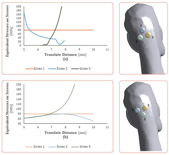
Figure 4.
(a) Equivalent stress values on screws in case of Rotate (0°), Pauwels angle (54°); (b) equivalent stress values on screws in case of Rotate (60°), Pauwels angle (54°). The numbers 1, 2 and 3 represent screw 1, screw 2 and screw 3 respectively.
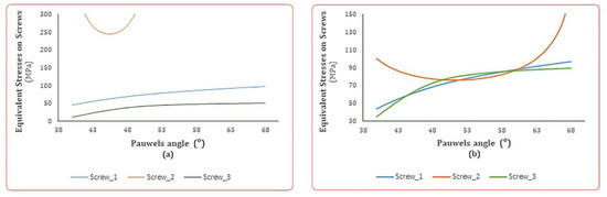
Figure 5.
(a) Equivalent stress values on screws in case of (a) Translate 1, 2, 3 (7 mm) and Rotation (0°), (b) Translate 1, 2, 3 (7 mm) and Rotation (60°).
When Figure 4 is analyzed, it is seen that the change in Translate values in all three screws had no effect on the equivalent stresses on screw 1, and the stress value is constant at approximately 80 MPa. In addition, it was found that the effect of the change in Translate values on the equivalent stresses on screws 2 and 3 was significant. When the changes in stress values on screw 2 are analyzed in both graphs, it is seen that the graph in Figure 4a is convex and the graph in Figure 4b is concave. When both graphs are analyzed, it is seen that the stress values on screws 1, 2, and 3 intersect in a certain region. These areas correspond to the regions where the stress values are low. The common Translate values of all three screws in these regions varied between 6.5 mm and 7.5 mm. These data inform us that it would be appropriate to send all three screws at a distance of 7 mm because the common areas of the graphs of all three screws correspond to this region. When the screws are evaluated alone, it is seen that the Translate values according to the lowest equivalent stress are different. But triple screws used in the treatment of femoral neck fractures should be considered together and they should share the stresses. Therefore, the Translate value was determined approximately. The effect of the Pauwels angle on the equivalent stresses in the screws is shown in Figure 5. In Figure 5a, the common Translate distance of the screws from the center is 7 mm, and the common Rotation angle is 0°. In Figure 5b, the distance from the center is 7 mm, and the Rotation angle is 60°.
In Figure 5a, it is observed that the stress values on screw 2 are at very extreme points. In Figure 5b, the stress values on all three screws intersect with each other. When the two graphs are analyzed, the Pauwels angle values in the cases where the stress values on the three screws are close to each other are the desired regions. When the common stresses close to each other on the screws are examined, it is observed from the graphs in Figure 5a,b that the most suitable range of the Pauwels angle is approximately between 45° and 58°.
As a result of the optimization, it is clearly seen that there is a correlation between the input parameters and the output parameters. During the analysis, the stresses on the fracture line and the screws are important for this study. For this reason, the most effective parameters on the output parameters determined in this study are given in Figure 6. According to the equivalent stresses on the fracture line and screw 1, the Pauwels angle parameter is very important. When the equivalent stresses on screws 2 and 3 are analyzed, it is found that the Translate 3 input parameter is the most important. Translate 2 input parameters was found to be the weakest parameter in all cases.
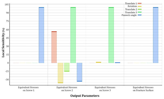
Figure 6.
The sensitivity levels of the input parameters on the stress values occurring in some regions on the system.
According to the equivalent stress values on screw 1 and the fracture site, only Pauwels angle has a significant effect. It is seen that the Pauwels angle has little effect only on screw 3. Apart from this, it is observed that its effectiveness is high on other screws and the fracture site. This allows us to consider Pauwels angle as an important parameter.
4. Discussion
The current study expands the knowledge base by providing a more nuanced understanding of the biomechanics involved in proximal femoral nailing (Figure 3 and Figure 6). For instance, a significant correlation between Pauwels angle and stress distribution has been discovered. This finding supports the Pauwels hypothesis that the Pauwels angle correlates with instability and increased shear forces, thus influencing the overall prognosis of the patient [22]. This study confirms this and offers biomechanical evidence supporting the clinical observations made in previous studies [23]. Similar studies have shown that the Pauwels angle is an important factor in the failure of fixation. The Pauwels angle produces high shear forces on the screws used for fracture stability. Similar results have been encountered in many studies, and the use of multiple screws has been recommended in Pauwels type II fractures, since the fracture line and the femoral neck axis are perpendicular to each other, thus avoiding shear force [24,25,26]. In the literature, it has been observed that with an increasing Pauwels angle, vertical shear forces in femoral neck fractures increase and stabilization of internal fixators occurs [7,27]. Therefore, determination of the optimal Pauwels angle has become important.
On the other hand, this study found that the rotational and translational parameters of the screw (Translate 1, 2, and 3) do not significantly affect stress distributions at the fracture surfaces. These findings challenge conventional wisdom regarding screw positioning and could have profound implications for surgical planning. Despite the emphasis placed on the exact screw positioning, the benefit may be marginal due to the inherent angular stability of modern cannulated screws. In similar studies, it is seen that the importance of each screw for fracture stability is different [6]. In this study, the posterior TSC was found to present a lower maximum equivalent von Mises stress value (occurring in screw No. 3) than the inverted TSC. In this study, a result confirming this information was obtained. Considering the stresses on the screws, it is seen that the values occurring in the posterior TSC are lower than those occurring in the inverted TSC (occurring in screw 2, Figure 4). In addition, when the stresses on all three screws are considered together, the most suitable configuration is the inverted triangle configuration when the Pauwels angle is 54° and the Translate value is 7 mm (Figure 5). As a result of different evaluations, it is seen that there is not much of a difference between the posterior triangular screws and the inverted triangular screws [6,28]. When the minimum values of the stresses occurring on the screws are considered in Figure 4, it is seen that the Translate value of all three screws is approximately 7 mm. Similar studies have shown that the distance from the inner surface of the screws to the cortex of the femoral neck should be less than 3 mm in screw fixation of FNFs. They also stated that the closer the screws are to the inner surface of the cortex of the femoral neck, the more favorable the healing at the fracture site [29,30]. In this study, Figure 4, the values of the Translate values near the femoral neck cortex are close to approximately 7 mm. Importantly, the von Mises equivalent stresses on the cannulated screws were investigated. As highlighted by [31], hardware failure is a significant contributor to poor outcomes in FNFs. By assessing the mechanical stress on the screws, this study offers insights that can contribute to the design and selection of more robust and efficient orthopedic hardware. This study can be further analyzed by comparing different Pauwels angles with femoral neck systems and four cannulated screws [32].
5. Conclusions
In conclusion, this study provides technical insights into the biomechanical aspects of FNF management with proximal femoral nails, suggesting that the Pauwels angle is a significant predictor of stress distribution. It also questions the conventional emphasis on precise screw positioning, potentially redefining surgical strategies. Considering the equivalent stresses in the fracture site, it was observed that the rotational and translational movements of the screws were negligible compared to the effect of Pauwels angle. Considering the stresses on the screws, it was observed that the values occurring in the posterior TSC were lower than those occurring in the inverted TSC. When the findings are combined with the information in the literature, it is seen that there is not a significant difference between the posterior TSC and the inverted TSC. Findings in this study call for a re-evaluation of current orthopedic practices and provide a solid foundation for future research in this domain. Future studies should continue to validate these findings in clinical settings and leverage this information to optimize orthopedic intervention.
Funding
This research received no external funding.
Institutional Review Board Statement
Not applicable.
Informed Consent Statement
Not applicable.
Data Availability Statement
The raw data supporting the conclusions of this article will be made available by the authors on request.
Acknowledgments
I would like to thank my esteemed Mehmet Nuri Konya (Afyonkarahisar Health Sciences University, Department of Orthopedics and Traumatology) for his help and support of my study.
Conflicts of Interest
The author declares no conflicts of interest. The funders had no role in the design of the study; in the collection, analyses, or interpretation of data; in the writing of the manuscript.
References
- Cummings, S.R.; Browner, W.; Cummings, S.R.; Black, D.M.; Nevitt, M.C.; Browner, W.; Genant, H.K.; Cauley, J.; Ensrud, K.; Scott, J.; et al. Bone Density at Various Sites for Prediction of Hip Fractures. Lancet 1993, 341, 72–75. [Google Scholar] [CrossRef]
- Zhou, L.; Lin, J.; Huang, A.; Gan, W.; Zhai, X.; Sun, K.; Huang, S.; Li, Z. Modified Cannulated Screw Fixation in the Treatment of Pauwels Type III Femoral Neck Fractures: A Biomechanical Study. Clin. Biomech. 2020, 74, 103–110. [Google Scholar] [CrossRef]
- Jiang, X.; Liang, K.; Du, G.; Chen, Y.; Tang, Y.; Geng, K. Biomechanical Evaluation of Different Internal Fixation Methods Based on Finite Element Analysis for Pauwels Type III Femoral Neck Fracture. Injury 2022, 53, 3115–3123. [Google Scholar] [CrossRef]
- Wang, F.; Liu, Y.; Zhang, C. Effectiveness of F-Shaped Screw Fixation Technique in Treatment of Pauwels Type Ⅲ Femoral Neck Fractures. Chin. J. Reparative Reconstr. Surg. 2018, 32, 1417–1420. [Google Scholar]
- Kuan, F.C.; Hsu, K.L.; Lin, C.L.; Hong, C.K.; Yeh, M.L.; Su, W.R. Biomechanical Properties of Off-Axis Screw in Pauwels III Femoral Neck Fracture Fixation: Bicortical Screw Construct Is Superior to Unicortical Screw Construct. Injury 2019, 50, 1889–1894. [Google Scholar] [CrossRef] [PubMed]
- Chantarapanich, N.; Jitprapaikulsarn, S.; Mahaisavariya, B.; Mahaisavariya, C. Comparative Biomechanical Performance of Two Configurations of Screw Constructs and Types Used to Stabilize Different Sites of Unstable Pauwels Type II Femoral Neck Fractures: A Finite Element Analysis. Med. Eng. Phys. 2022, 107, 1038–1056. [Google Scholar] [CrossRef]
- Wang, G.; Tang, Y.; Wu, X.; Yang, H. Finite Element Analysis of a New Plate for Pauwels Type III Femoral Neck Fractures. J. Int. Med. Res. 2020, 48. [Google Scholar] [CrossRef] [PubMed]
- Mansur, H.; Alvarez, R.; Freitas, A.; Gonçalves, C.B.; Ramos, M.R.F. Biomechanical Analysis of Femoral Neck Fracture Fixation in Synthetic Bone. Acta Ortop. Bras. 2018, 26, 162–165. [Google Scholar] [CrossRef] [PubMed]
- Dong, Q.; Han, Z.; Zhang, Y.G.; Sun, X.; Ma, X.L. Comparison of Transverse Cancellous Lag Screw and Ordinary Cannulated Screw Fixations in Treatment of Vertical Femoral Neck Fractures. Orthop. Surg. 2019, 11, 595–603. [Google Scholar] [CrossRef]
- Zhang, B.; Liu, J.; Zhu, Y.; Zhang, W. A New Configuration of Cannulated Screw Fixation in the Treatment of Vertical Femoral Neck Fractures. Int. Orthop. 2018, 42, 1949–1955. [Google Scholar] [CrossRef]
- Shahzamanian, M.M.; Banerjee, R.; Dahotre, N.B.; Srinivasa, A.R.; Reddy, J.N. Analysis of Stress Shielding Reduction in Bone Fracture Fixation Implant Using Functionally Graded Materials. Compos. Struct. 2023, 321, 117262. [Google Scholar] [CrossRef]
- Viceconti, M.; Olsen, S.; Nolte, L.P.; Burton, K. Extracting Clinically Relevant Data from Finite Element Simulations. Clin. Biomech. 2005, 20, 451–454. [Google Scholar] [CrossRef]
- Wojtaszek, M.; Śleboda, T.; Czulak, A.; Weber, G.; Hufenbach, W.A. Quasi-Static and Dynamic Tensile Properties of Ti-6Al-4V Alloy. Arch. Metall. Mater. 2013, 58, 1261–1265. [Google Scholar] [CrossRef]
- Mei, J.; Liu, S.; Jia, G.; Cui, X.; Jiang, C.; Ou, Y. Finite Element Analysis of the Effect of Cannulated Screw Placement and Drilling Frequency on Femoral Neck Fracture Fixation. Injury 2014, 45, 2045–2050. [Google Scholar] [CrossRef]
- Paternina Baena, J.O.; González Estrada, O.A.; Villegas, D.F. Structural Analysis of Bone by Segmentation and Finite Element Analysis in Patients with Osteoporosis. J. Phys. Conf. Ser. 2021, 2046, 012019. [Google Scholar] [CrossRef]
- Oken, O.F.; Soydan, Z.; Yildirim, A.O.; Gulcek, M.; Ozlu, K.; Ucaner, A. Performance of Modified Anatomic Plates Is Comparable to Proximal Femoral Nail, Dynamic Hip Screw and Anatomic Plates: Finite Element and Biomechanical Testing. Injury 2011, 42, 1077–1083. [Google Scholar] [CrossRef] [PubMed]
- Li, J.; Zhao, Z.; Yin, P.; Zhang, L.; Tang, P. Comparison of Three Different Internal Fixation Implants in Treatment of Femoral Neck Fracture—A Finite Element Analysis. J. Orthop. Surg. Res. 2019, 14, 76. [Google Scholar] [CrossRef] [PubMed]
- Zeng, W.; Liu, Y.; Hou, X. Biomechanical Evaluation of Internal Fixation Implants for Femoral Neck Fractures: A Comparative Finite Element Analysis. Comput. Methods Programs Biomed. 2020, 196, 105714. [Google Scholar] [CrossRef]
- Chen, W.P.; Tai, C.L.; Shih, C.H.; Hsieh, P.H.; Leou, M.C.; Lee, M.S. Selection of Fixation Devices in Proximal Femur Rotational Osteotomy: Clinical Complications and Finite Element Analysis. Clin. Biomech. 2004, 19, 255–262. [Google Scholar] [CrossRef]
- Kilickap, E.; Huseyinoglu, M. Optimization and Modelling of Burrheight by Using Response Surface Methodology and Genetic Algorithm in Drilling AISI 316. J. Eng. Fac. Eng. Dicle Univ. 2010, 1, 71–80. [Google Scholar]
- Shiri, S. A Robust Optimization Approach for Design of a General Purpose Heat Source. J. Space Saf. Eng. 2021, 8, 211–216. [Google Scholar] [CrossRef]
- Pauwels, F. Der Schenkelhalsbruch: Ein Mechanisches Problem. Br. J. Surg. 2005, 23, 874. [Google Scholar] [CrossRef]
- Gupta, R.K.; Sangwan, K.; Kamboj, P.; Punia, S.S.; Walecha, P. Unstable Trochanteric Fractures: The Role of Lateral Wall Reconstruction. Int. Orthop. 2010, 34, 125–129. [Google Scholar] [CrossRef]
- Wang, C.T.; Chen, J.W.; Wu, K.; Chen, C.S.; Chen, W.C.; Pao, J.L.; Chang, C.H.; Lan, T.Y. Suboptimal Outcomes after Closed Reduction and Internal Fixation of Displaced Femoral Neck Fractures in Middle-Aged Patients: Is Internal Fixation Adequate in This Age Group? BMC Musculoskelet. Disord. 2018, 19, 190. [Google Scholar] [CrossRef] [PubMed]
- Tianye, L.; Peng, Y.; Jingli, X.; QiuShi, W.; GuangQuan, Z.; Wei, H.; Qingwen, Z. Finite Element Analysis of Different Internal Fixation Methods for the Treatment of Pauwels Type III Femoral Neck Fracture. Biomed. Pharmacother. 2019, 112, 108658. [Google Scholar] [CrossRef]
- Cha, Y.H.; Yoo, J., II; Hwang, S.Y.; Kim, K.J.; Kim, H.Y.; Choy, W.S.; Hwang, S.C. Biomechanical Evaluation of Internal Fixation of Pauwels Type III Femoral Neck Fractures: A Systematic Review of Various Fixation Methods. CiOS Clin. Orthop. Surg. 2019, 11, 1–14. [Google Scholar] [CrossRef]
- Wang, F.; Liu, Y.; Huo, Y.; Wang, Z.; Zhang, J.; Xu, M.; Ma, K.; Wang, L.; Lu, Y.; Cheng, L.; et al. Biomechanical Study of Internal Fixation Methods for Femoral Neck Fractures Based on Pauwels Angle. Front. Bioeng. Biotechnol. 2023, 11, 1143575. [Google Scholar] [CrossRef] [PubMed]
- Li, J.; Wang, M.; Li, L.; Zhang, H.; Hao, M.; Li, C.; Han, L.; Zhou, J.; Wang, K. Finite Element Analysis of Different Configurations of Fully Threaded Cannulated Screw in the Treatment of Unstable Femoral Neck Fractures. J. Orthop. Surg. Res. 2018, 13, 272. [Google Scholar] [CrossRef]
- Zhang, R.Y.; Li, J.T.; Zhao, J.X.; Zhao, Z.; Zhang, L.C.; Yun, C.; Su, X.Y.; Tang, P.F. Comparison of Oblique Triangular Configuration and Inverted Equilateral Triangular Configuration of Three Cannulated Screws in Treating Unstable Femoral Neck Fracture: A Finite Element Analysis. Injury 2022, 53, 353–361. [Google Scholar] [CrossRef]
- Lindequist, S.; Wredmark, T.; Eriksson, S.A.V.; Samnegård, E. Screw Positions in Femoral Neck Fractures: Comparison of Two Different Screw Positions in Cadavers. Acta Orthop. 1993, 64, 67–70. [Google Scholar] [CrossRef]
- Fortis, A.P.; Dimas, A.; Lamprakis, A.A. Expandable Nailing System for Tibial Shaft Fractures. Injury 2008, 39, 940–946. [Google Scholar] [CrossRef] [PubMed]
- Lin, H.; Lai, C.; Zhou, Z.; Wang, C.; Yu, X. Femoral Neck System vs. Four Cannulated Screws in the Treatment of Pauwels III Femoral Neck Fracture. J. Orthop. Sci. 2023, 28, 1373–1378. [Google Scholar] [CrossRef] [PubMed]
Disclaimer/Publisher’s Note: The statements, opinions and data contained in all publications are solely those of the individual author(s) and contributor(s) and not of MDPI and/or the editor(s). MDPI and/or the editor(s) disclaim responsibility for any injury to people or property resulting from any ideas, methods, instructions or products referred to in the content. |
© 2024 by the author. Licensee MDPI, Basel, Switzerland. This article is an open access article distributed under the terms and conditions of the Creative Commons Attribution (CC BY) license (https://creativecommons.org/licenses/by/4.0/).