

Proactive Braking Control System for Collision Avoidance during Right Turns with Occluded Vision at an Intersection


Abstract
1. Introduction
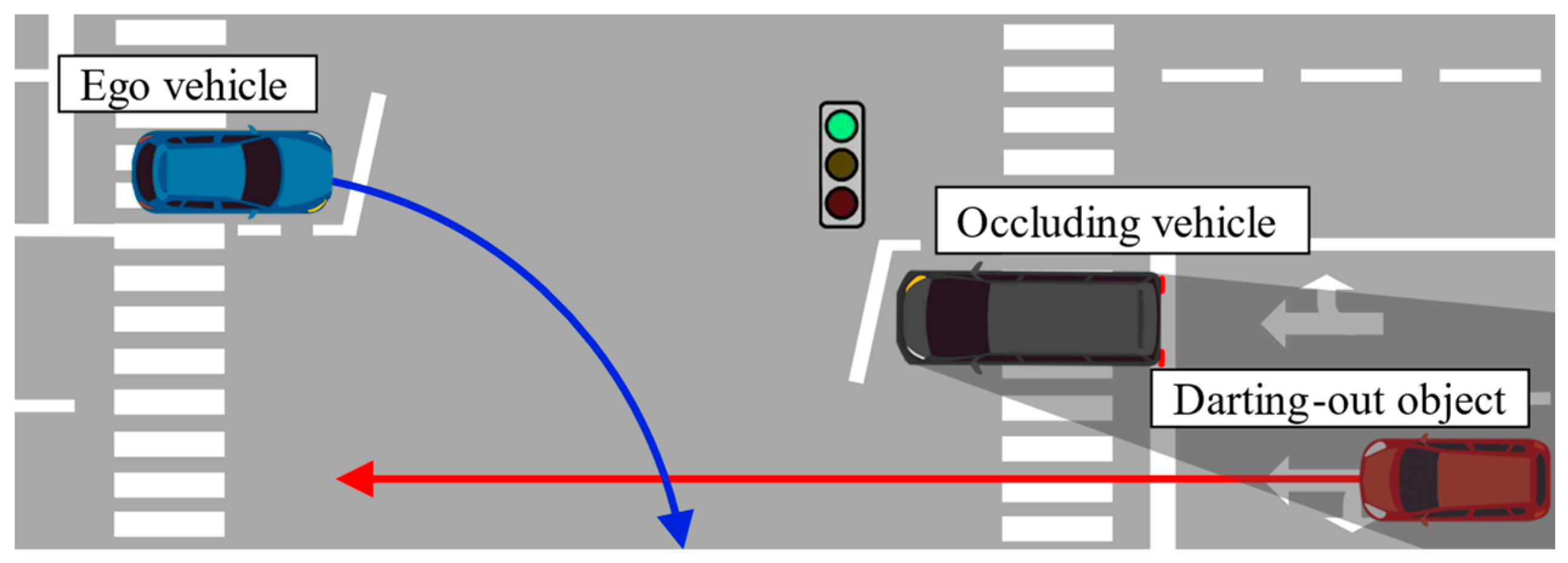
2. Risk Prediction under Occluded Vision for Proactive Braking Control Design
2.1. Design Concept
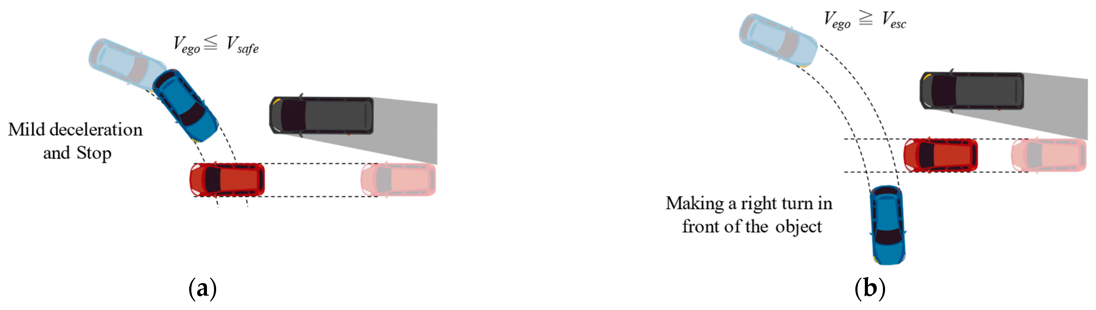
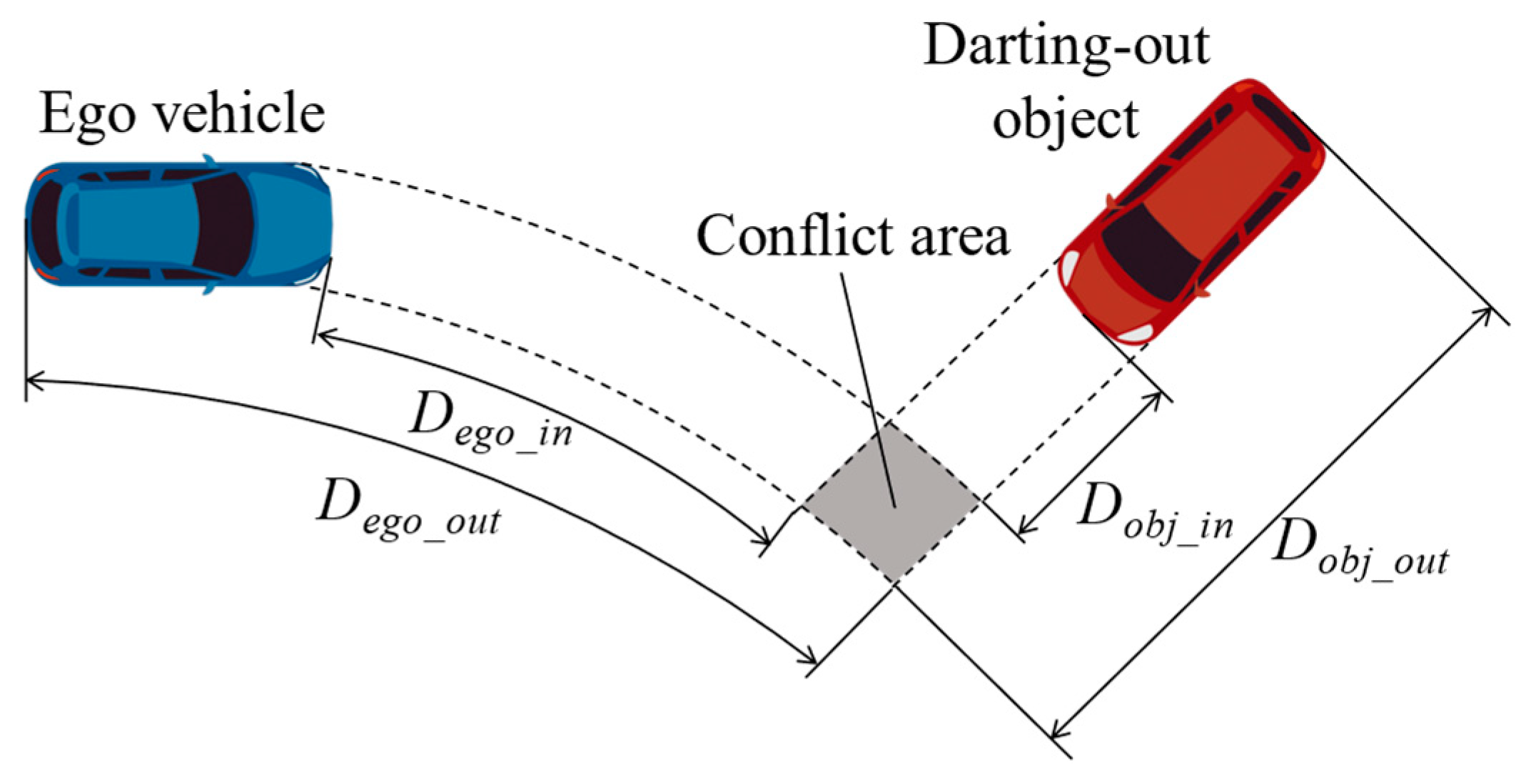
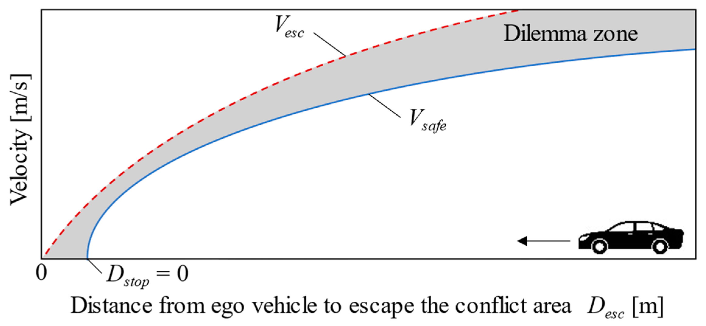
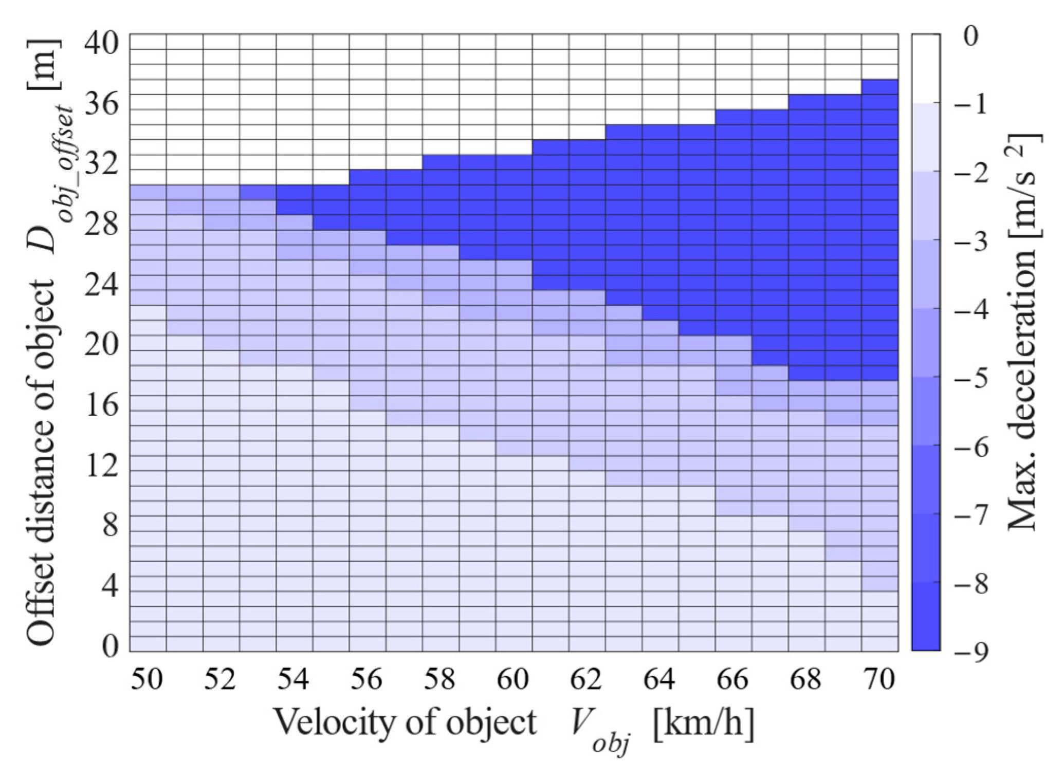
2.2. Quantification of Hazardous Speed Region for Right Turn
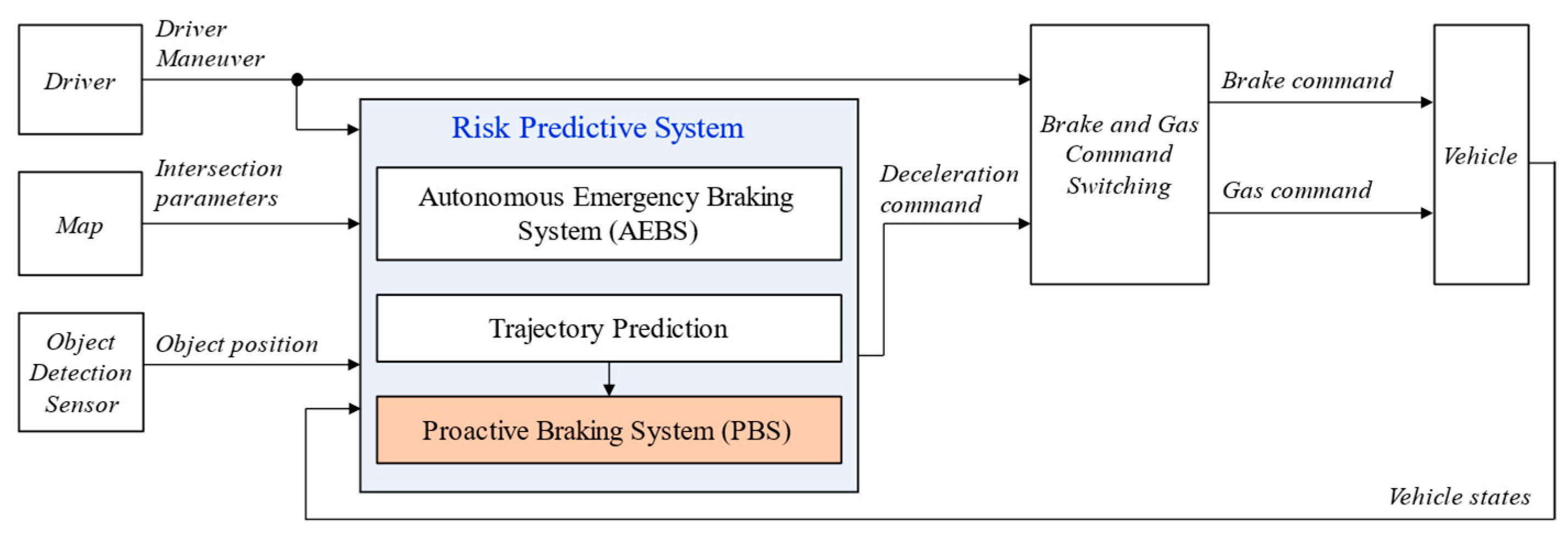
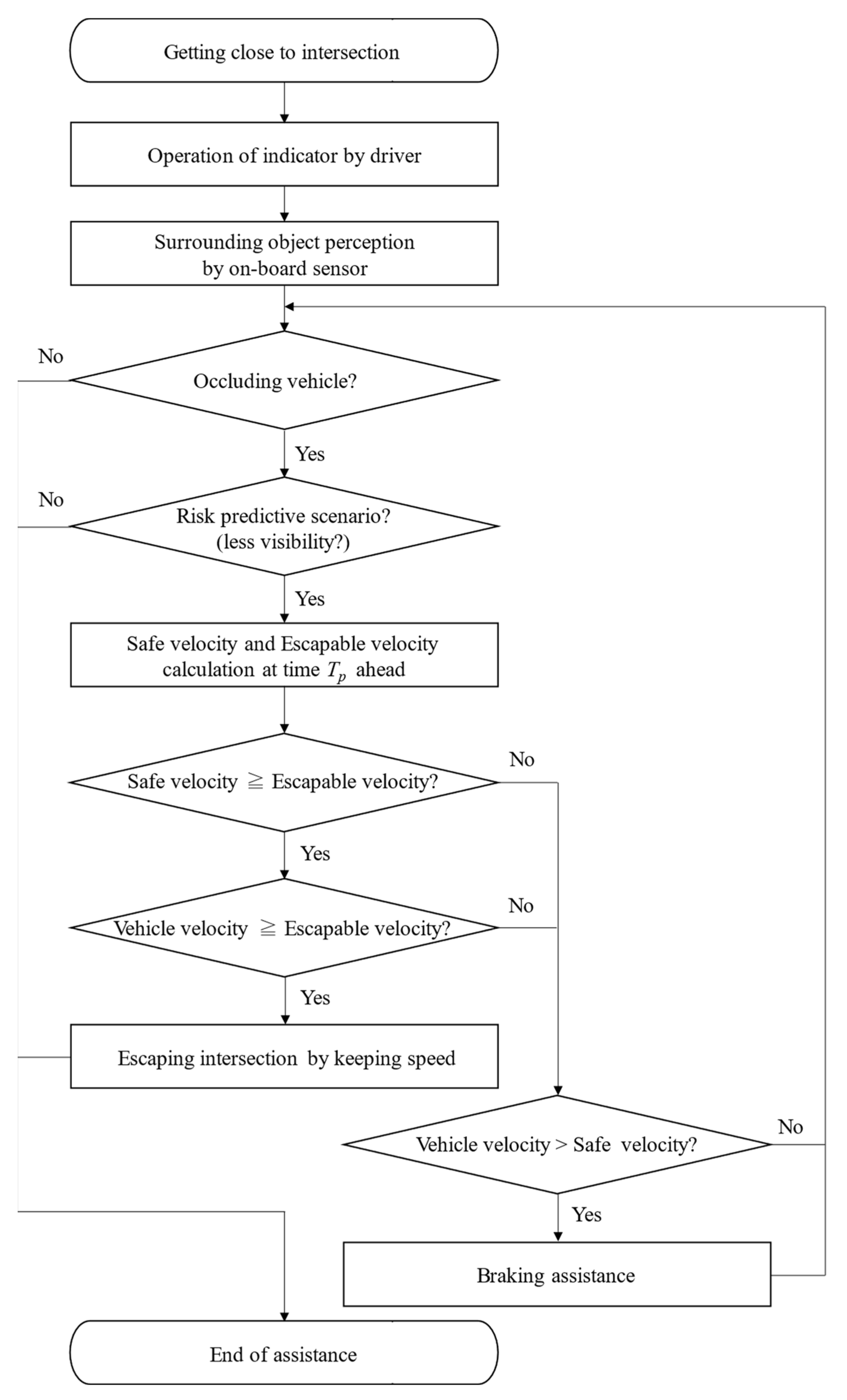
3. Collision Risk Avoidance Algorithm
3.1. Judgment of Driving Behavior by PBS
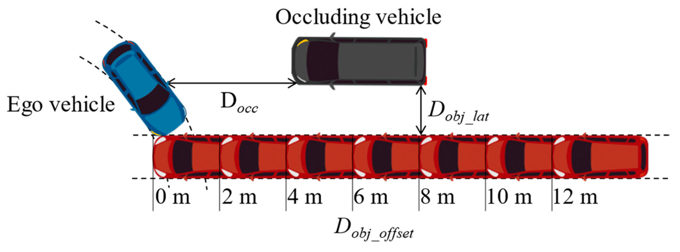
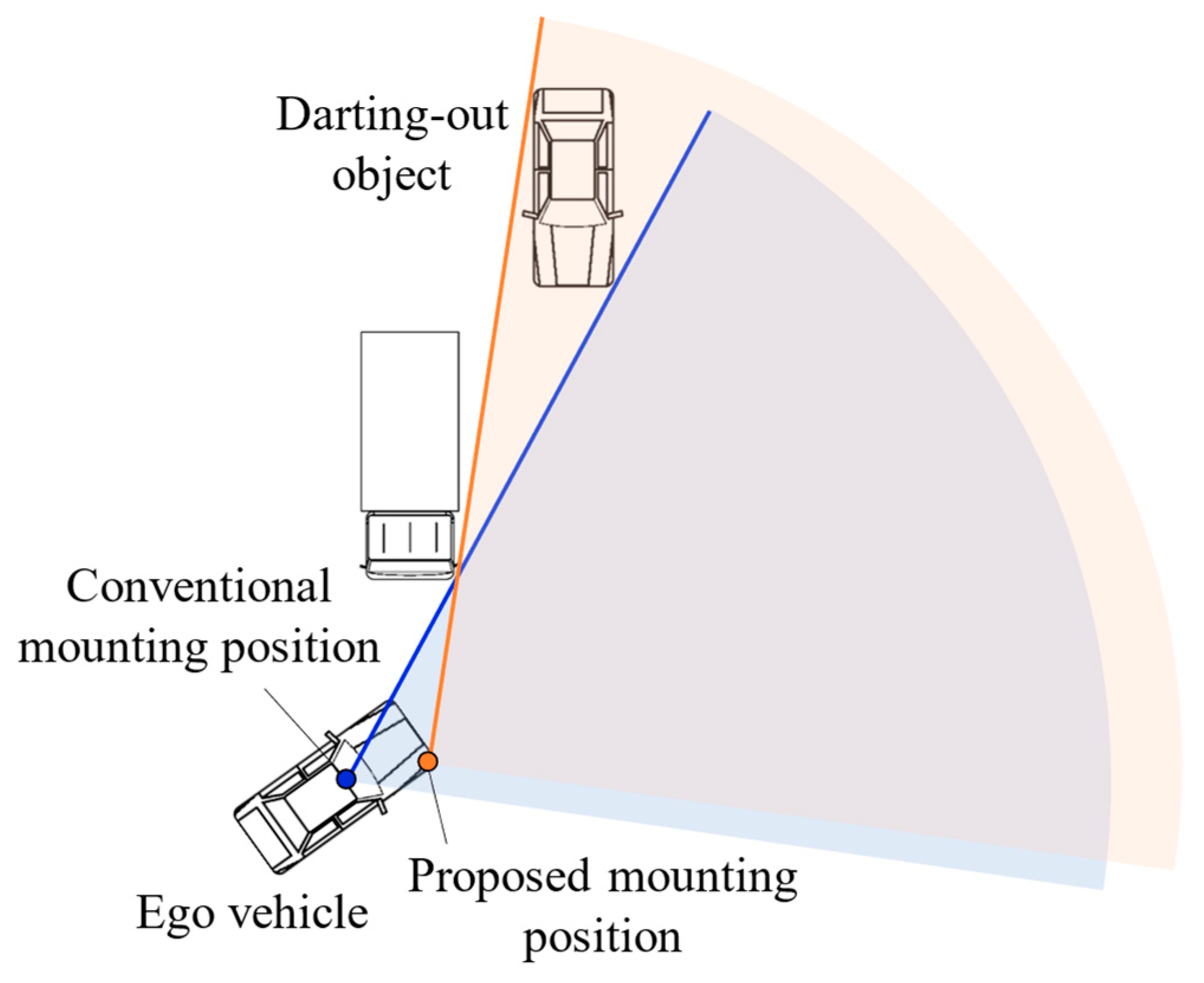
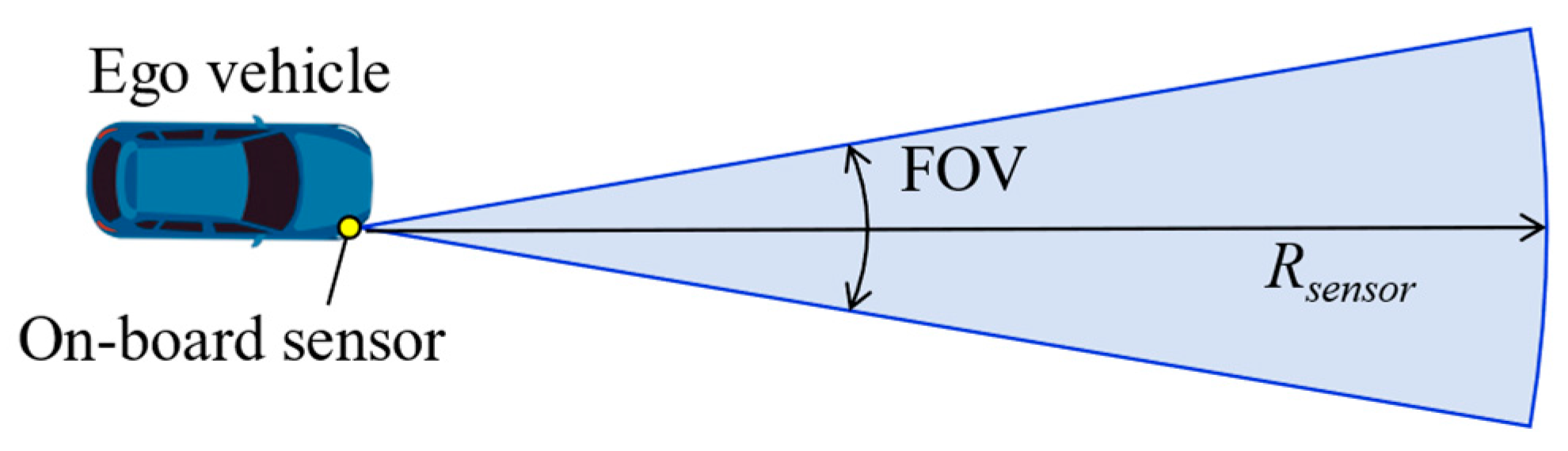
3.2. Sensor Position and Assistance after Stopping
4. System Verification with Full-Vehicle Simulation
4.1. Autonomous Emergency Braking System
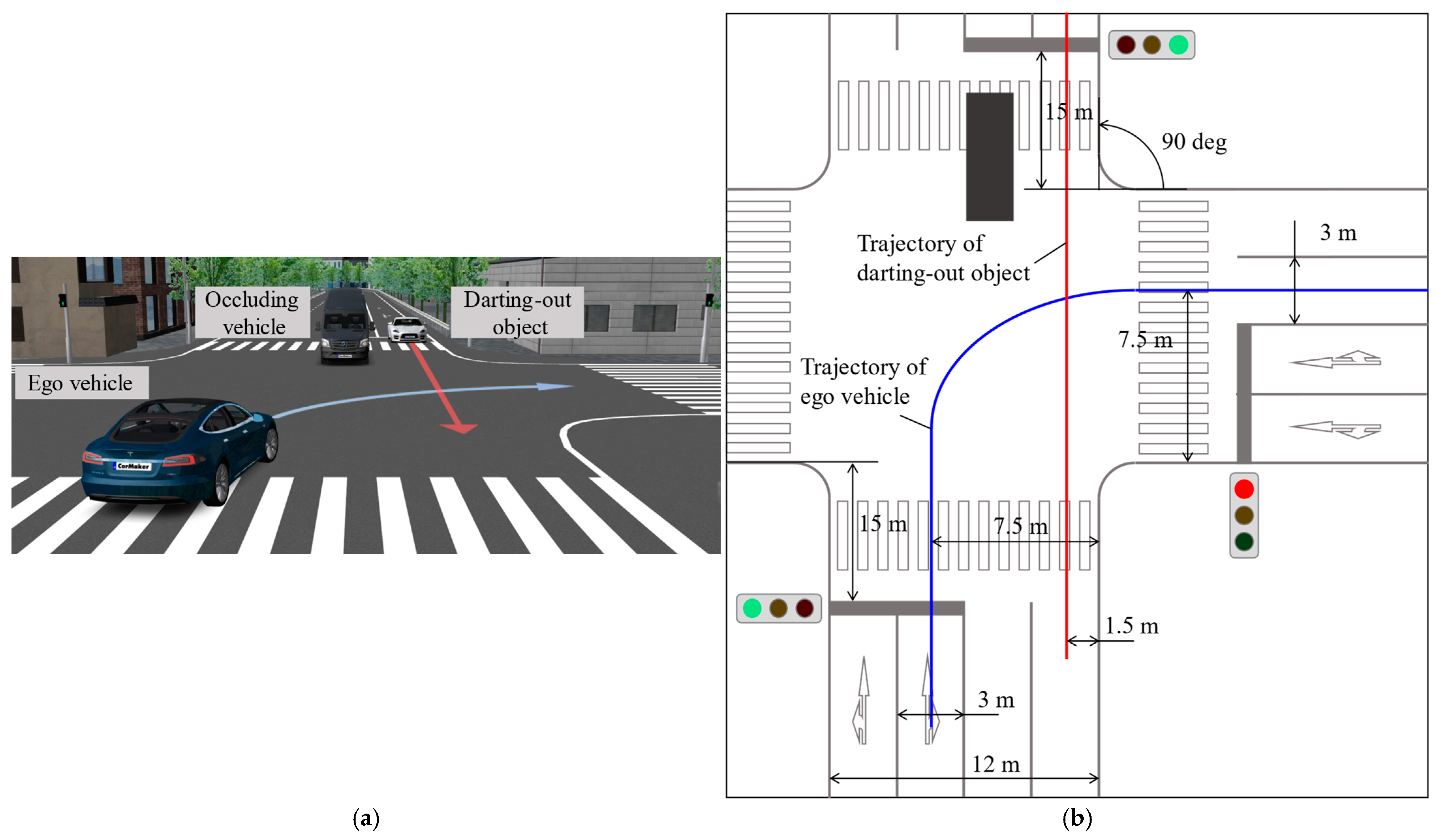
4.2. Simulation Conditions
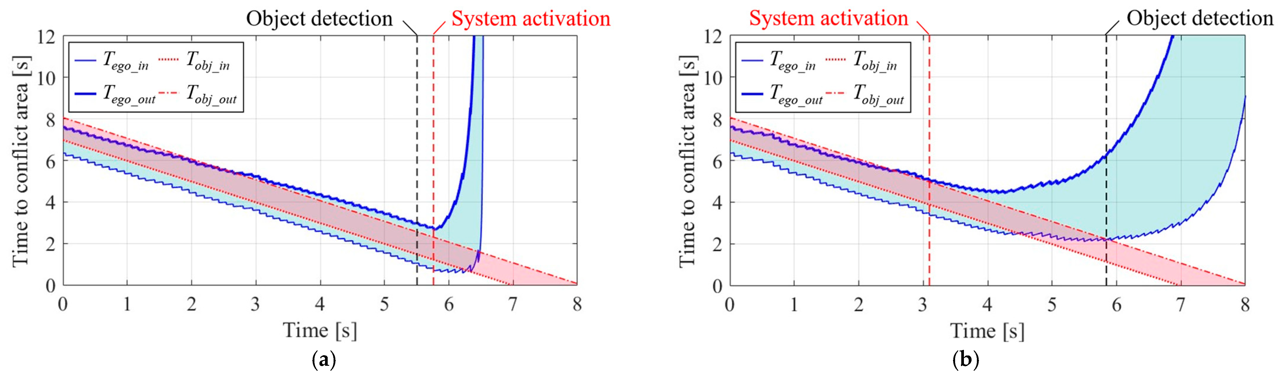
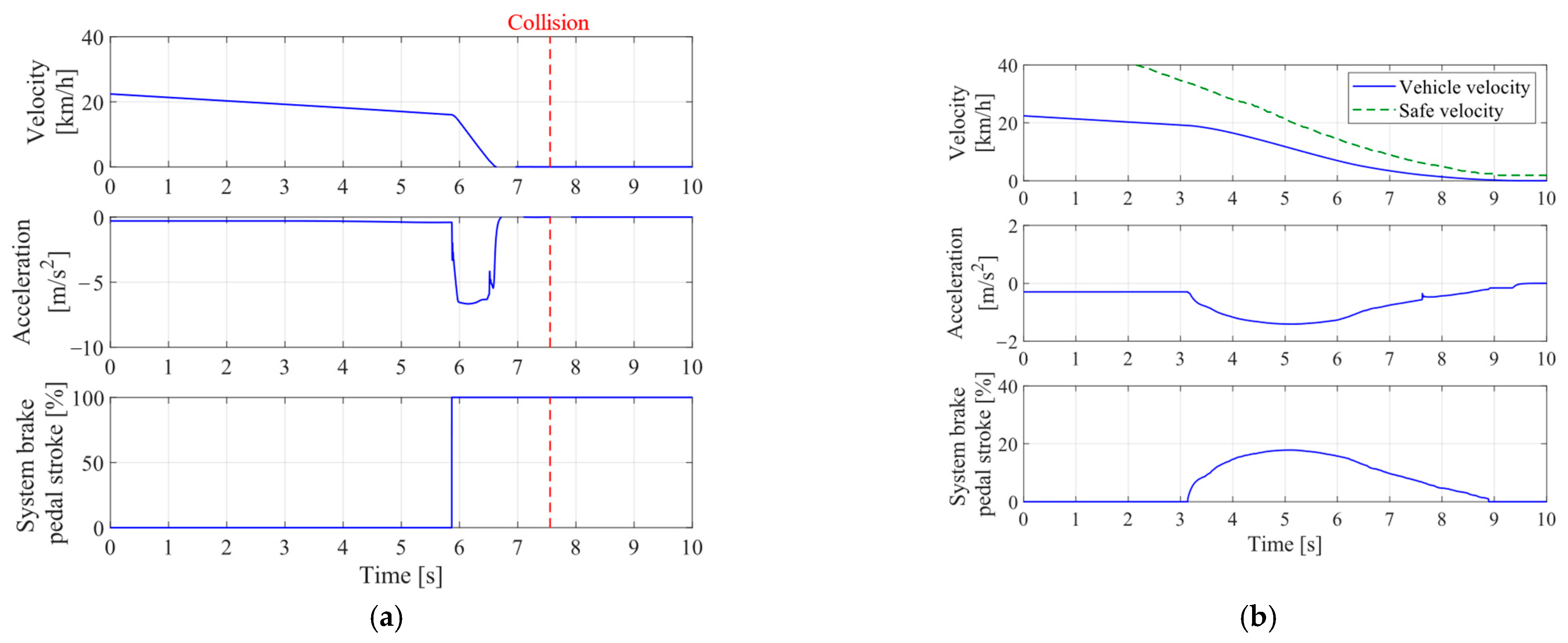
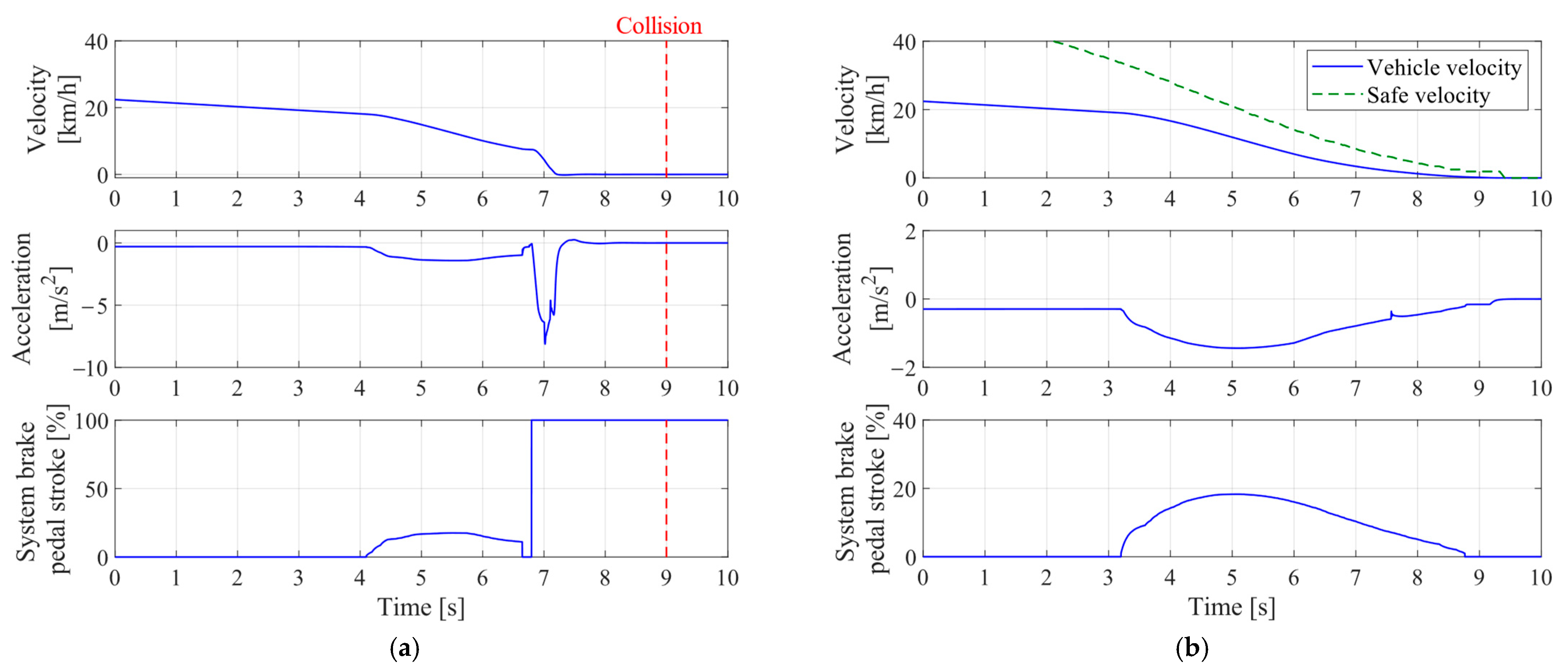
4.3. Results and Discussions
5. Conclusions
Author Contributions
Funding
Institutional Review Board Statement
Informed Consent Statement
Data Availability Statement
Conflicts of Interest
References
- National Police Agency Traffic Bureau. Status of Traffic Fatal Accident Occurrence and Status of Violation Control of Road Traffic Act in 2022; Portal Site of Official Statistics of Japan: Tokyo, Japan, 2023; p. 33.
- Institute for Traffic Accident Research and Data Analysis (ITARDA). Right turn traffic accidents in signalized Intersection. ITARDA Inf. 2012, 95, 4. [Google Scholar]
- Sander, U. Opportunities and Limitations for Intersection Collision Intervention—A Study of Real World, Left Turn Across Path, Accidents. Accid. Anal. Prev. 2017, 99, 342–355. [Google Scholar] [CrossRef]
- Sander, U.; Lubbe, N.; Pietzsch, S. Intersection AEB implementation strategies for left turn across path crashes. Traffic Inj. Prev. 2019, 20, S119–S125. [Google Scholar] [CrossRef] [PubMed]
- Hillenbrand, J.; Spieker, A.M.; Kroschel, K. A multilevel collision mitigation approach -its situation assessment, decision making, and performance tradeoffs. IEEE Trans. Intell. Transp. Syst. 2006, 7, 528–540. [Google Scholar] [CrossRef]
- Brännström, M.; Coelingh, E.; Sjöberg, J. Model-based threat assessment for avoiding arbitrary vehicle collisions. IEEE Trans. Intell. Transp. Syst. 2010, 11, 658–669. [Google Scholar] [CrossRef]
- Brännström, M.; Sjöberg, J.; Helgesson, L.; Christiansson, M. A Real-time Implementation of an Intersection Collision Avoidance System. IFAC Proc. 2011, 44, 9794–9798. [Google Scholar] [CrossRef]
- Nobukawa, K.; Gordon, T.J.; Barnes, M.A.; Goodsell, R.J. A comprehensive speed control model for human drivers with application to intersection left turns. In Proceedings of the 2011 American Control Conference, San Francisco, CA, USA, 29 June–1 July 2011; pp. 3065–3070. [Google Scholar] [CrossRef]
- Brännström, M.; Sandblom, F.; Hammarstrand, L. A probabilistic framework for decision-making in collision avoidance systems. IEEE Trans. Intell. Transp. Syst. 2013, 14, 637–648. [Google Scholar] [CrossRef]
- Yoshihira, M.; Watanabe, S.; Nishira, H.; Kishi, N. Developing an Autonomous Vehicle Control System for Intersections Using Obstacle/Blind Spot Detection Frames. SAE Tech. Pap. 2016. [Google Scholar] [CrossRef]
- Arikere, A.; Yang, D.; Klomp, M. Optimal motion control for collision avoidance at Left Turn Across Path/Opposite Direction intersection scenarios using electric propulsion. Veh. Syst. Dyn. 2019, 57, 637–664. [Google Scholar] [CrossRef]
- Fors, V.; Olofsson, B.; Nielsen, L. Yaw-Moment Control At-the-Limit of Friction Using Individual Front-Wheel Steering and Four-Wheel Braking. In Proceedings of the 9th IFAC Symposium on Advances in Automotive Control, Orléans, France, 23–27 June 2019; Volume 52, pp. 458–464. [Google Scholar] [CrossRef]
- Pierowicz, J.A. Intersection Collision Avoidance Using ITS Countermeasures. 2000. Available online: http://hdl.handle.net/2027/mdp.39015075257181 (accessed on 8 February 2024).
- Misener, J.A. Cooperative Intersection Collision Avoidance System (CICAS): Signalized Left Turn Assist and Traffic Signal Adaptation; University of California: Berkeley, CA, USA, 2010; Report No.: UCB-ITS-PRR-2010-20; Available online: https://trid.trb.org/view.aspx?id=919887 (accessed on 8 February 2024).
- Hafner, M.R.; Cunningham, D.; Caminiti, L.; Del Vecchioet, D. Cooperative collision avoidance at intersections: Algorithms and experiments. IEEE Trans. Intell. Transp. Syst. 2013, 14, 1162–1175. [Google Scholar] [CrossRef]
- Nakamura, S.; Suganuma, H.; Kikuchi, K.; Homma, R. Effect Evaluation of Vehicle-Infrastructure Cooperative Right-Turn Collision Prevention System. Trans. Soc. Automot. Eng. Jpn. 2015, 46, 449–454. [Google Scholar] [CrossRef]
- Hirose, T.; Ohtsuka, Y.; Gokan, M. Activation Timing of a Collision Avoidance System with V2V Communication; SAE Technical Paper 2017-01-0039; SAE: Warrendale, PA, USA, 2017. [Google Scholar] [CrossRef]
- Yonekawa, T.; Murano, T.; Aga, M. Accident analysis on intersection right turning by using driving simulator. Int. J. Veh. Saf. (IJVS) 2014, 7, 17–36. [Google Scholar] [CrossRef]
- Bärgman, J.; Smith, K.; Werneke, J. Quantifying drivers’ comfort-zone and dread-zone boundaries in left turn across path/opposite direction (LTAP/OD) scenarios. Transp. Res. Part F Traffic Psychol. Behav. 2015, 35, 170–184. [Google Scholar] [CrossRef]
- Wang, X.; Zhao, D.; Peng, H.; LeBlanc, D.J. Analysis of unprotected intersection left-turn conflicts based on naturalistic driving data. In Proceedings of the IEEE Intelligent Vehicles Symposium (IV), Los Angeles, CA, USA, 11–14 June 2017; pp. 218–223. [Google Scholar] [CrossRef]
- Appiah, J.; King, F.A.; Fontaine, M.D.; Cottrell, B.H. Left turn crash risk analysis: Development of a microsimulation modeling approach. Accid. Anal. Prev. 2020, 144, 105591. [Google Scholar] [CrossRef]
- Kusakari, Y.; Oikawa, S.; Matsui, Y.; Kubota, N. Effect of Human–Machine Interface of a Vehicle on Right-Turn Maneuver at Intersections using a Driving Simulator. In Proceedings of the IEEE International Conference on Systems, Man, and Cybernetics (SMC), Melbourne, Australia, 17–20 October 2021; pp. 1607–1612. [Google Scholar] [CrossRef]
- Zafian, T.; Ryan, A.; Agrawal, R.; Samuel, S.; Knodler, M. Using SHRP2 NDS data to examine infrastructure and other factors contributing to older driver crashes during left turns at signalized intersections. Accid. Anal. Prev. 2021, 156, 106141. [Google Scholar] [CrossRef] [PubMed]
- Fujinami, Y.; Raksincharoensak, P.; Ulbricht, D.; Adomat, R. Risk Predictive Driver Assistance System for Collision Avoidance in Intersection Right Turns. J. Robot. Mechatron. 2018, 30, 15–23. [Google Scholar] [CrossRef]
- Fujinami, Y.; Raksincharoensak, P.; Arita, S.; Kato, R. Experimental Validation on Intersection Turning Trajectory Prediction Method for Advanced Driver Assistance System Based on Triclothoidal Curves. Appl. Sci. 2021, 11, 5900. [Google Scholar] [CrossRef]
- Gazis, D.; Herman, R.; Maradudin, A. The problem of the amber signal light in traffic flow. Oper. Res. 1960, 8, 112–132. [Google Scholar] [CrossRef]
- Allen, B.L.; Shin, B.T.; Copper, P.J. Analysis of traffic conflicts and collisions. Transp. Res. Rec. 1978, 667, 67–74. [Google Scholar]
- Perri, G.; Vaiana, R. Road Safety Management of Uncontrolled Access Points: Design Criteria and Insights into Risk Factors. Appl. Sci. 2022, 12, 12661. [Google Scholar] [CrossRef]
- Scanlon, J.M.; Sherony, R.; Gabler, H.C. Earliest Sensor Detection Opportunity for Left Turn across Path Opposite Direction Crashes. IEEE Trans. Intell. Veh. 2017, 2, 62–70. [Google Scholar] [CrossRef]
- Saito, Y.; Raksincharoensak, P.; Inoue, H.; EI-Haji, M.; Freudenmann, T. Context-Sensitive Hazard Anticipation Based on Driver Behavior Analysis and Cause-and-Effect Chain Study. In Proceedings of the 14th International Symposium on Advanced Vehicle Control (AVEC’18), Beijing, China, 16–20 July 2018; pp. 1–6. [Google Scholar]
- Thal, S.; Wallis, P.; Henze, R.; Hasegawa, R.; Teranishi, S.; Nakamura, H.; Kitajima, S.; Abe, G. Comparison of German and Japanese Urban Intersection Data for Internationally Harmonized Test Procedures. In Proceedings of the 7th International Symposium on Future Active Safety Technology towards zero-traffic-accidents (FAST-zero’23), Kanazawa, Japan, 8–11 November 2023; pp. 1–6. [Google Scholar]


| Definition | Symbol | Value | Unit |
|---|---|---|---|
| Acc. for mild deceleration | −2.94 | m/s2 | |
| System activation delay time | 0.1 | s | |
| Prediction time | 2.0 | s | |
| Post Encroachment Time | 1.0 | s | |
| Virtual darting-out velocity | 50 | km/h |
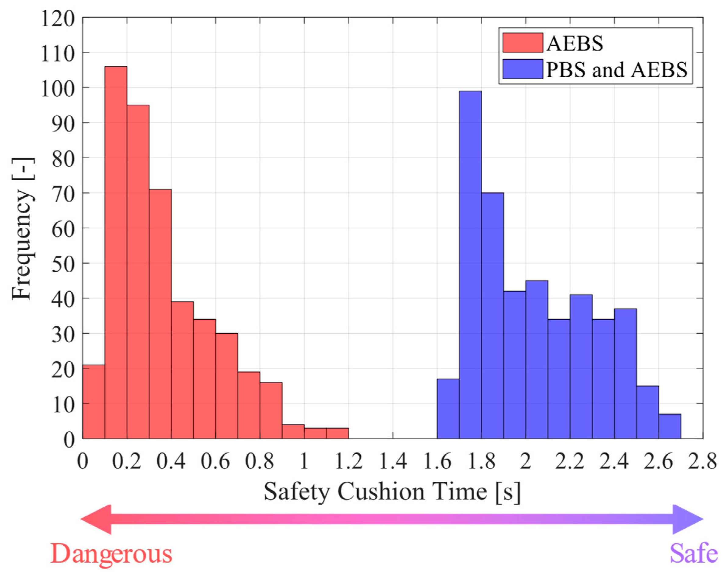
| Criticality Level | AEBS | PBS and AEBS |
|---|---|---|
| High level (SCT < 1 s) | 98.6% | 0% |
| Middle level (1 s ≤ SCT ≤ 2 s) | 1.4% | 51.7% |
Disclaimer/Publisher’s Note: The statements, opinions and data contained in all publications are solely those of the individual author(s) and contributor(s) and not of MDPI and/or the editor(s). MDPI and/or the editor(s) disclaim responsibility for any injury to people or property resulting from any ideas, methods, instructions or products referred to in the content. |
© 2024 by the authors. Licensee MDPI, Basel, Switzerland. This article is an open access article distributed under the terms and conditions of the Creative Commons Attribution (CC BY) license (https://creativecommons.org/licenses/by/4.0/).
Share and Cite
Aoki, S.; Fujinami, Y.; Raksincharoensak, P.; Henze, R. Proactive Braking Control System for Collision Avoidance during Right Turns with Occluded Vision at an Intersection. Appl. Sci. 2024, 14, 2661. https://doi.org/10.3390/app14062661
Aoki S, Fujinami Y, Raksincharoensak P, Henze R. Proactive Braking Control System for Collision Avoidance during Right Turns with Occluded Vision at an Intersection. Applied Sciences. 2024; 14(6):2661. https://doi.org/10.3390/app14062661
Chicago/Turabian StyleAoki, Sota, Yohei Fujinami, Pongsathorn Raksincharoensak, and Roman Henze. 2024. "Proactive Braking Control System for Collision Avoidance during Right Turns with Occluded Vision at an Intersection" Applied Sciences 14, no. 6: 2661. https://doi.org/10.3390/app14062661
APA StyleAoki, S., Fujinami, Y., Raksincharoensak, P., & Henze, R. (2024). Proactive Braking Control System for Collision Avoidance during Right Turns with Occluded Vision at an Intersection. Applied Sciences, 14(6), 2661. https://doi.org/10.3390/app14062661