1. Introduction
In the realm of culvert engineering, box culverts serve as significant structural entities and are typically utilized in transportation infrastructure such as highways, railways, and canals. They offer the ability to traverse geographical impediments such as river crossings and sewage pipelines. Box culverts function as reliable conduits for water flow and as substitutes for bridges, ensuring the normal transit of various types of vehicles. They contribute to a reduction in traffic incidents and help safeguard the natural environment [
1,
2,
3].
During the design process of a box culvert, the size of the design should take into account, as well as factors such as the required flow rate and bridge dimensions to ensure its capacity to withstand the anticipated load. If the sizing is not appropriately designed, it may result in instability of the box culvert structure and blockage of water flow, among other issues. Consequently, in the preliminary design phase, engineers often expend additional time in design selection and troubleshooting. These processes often present the challenges of extensive modeling efforts, time consumption, and low efficiency.
In recent years, with the rapid advancement of information technology, Building Information Modeling (BIM) has been widely used in different construction engineering fields, and its applications include, but are not limited to, visualization management, three-dimensional modeling, cost estimation, design review, collision detection, on-site construction management, and integration with point cloud technology such as for historical building maintenance [
4,
5,
6,
7,
8]. BIM has played a pivotal role in the digital transformation of the construction industry [
9,
10]. BIM’s parametric modeling improves design flexibility and efficiency and is extremely beneficial for simple and repetitive structures, such as box culverts, as it replaces cumbersome and time-consuming manual processes, substantially reducing the time and effort invested in projects [
11,
12]. In a BIM-based environment, engineers can quickly adjust and generate box culvert models with different dimensions, numbers of box chambers, and intersection angles to meet variable design requirements and site conditions. Therefore, it is necessary to explore the parametric modeling of box culverts based on BIM.
Typically, box culverts require internal force analysis and structural verification after the preliminary design phase, which is primarily achieved through Finite Element Analysis (FEA) software such as ANSYS and Midas. On the one hand, mainstream BIM software platforms such as Revit, Rhino, and MicroStation do not match these programs in terms of FEA capabilities. On the other hand, mainstream finite element software cannot be used to perform parametric design, necessitating the conversion of BIM models in the structural verification process. However, there are limited interoperability, untimely exchanges of information, and even errors in the results of exchanges between mainstream BIM software and structural analysis software models [
6,
13]. Liu et al. [
13] indicated that complex nodes (e.g., connections between inclined beams and columns of unequal height) fail to show the differences between irregular nodes and other nodes after conversion to structural analysis software and must be modified manually, which directly leads to difficulty when engineers try to utilize BIM in the structural design stage [
9,
10]. Furthermore, BIM’s high integration can coordinate and integrate all aspects of architectural design, construction, and operation processes, thus improving project performance and enterprise benefits [
14,
15]. However, when conducting structural analysis, the inability of the results from finite element software to effectively return to the BIM platform and realize internal force visualization based on BIM weakens BIM’s integration. This impedes effective data sharing and integration throughout the design lifecycle, thereby reducing overall project efficiency and quality. Therefore, bidirectional data exchange between BIM and finite element software is a difficulty and a focus in the application of BIM in structural analysis.
1.1. Parametric Modeling
Parametric design, facilitated by specialized parametric software, establishes parametric relationships between the constraints of an engineering project and the resultant design outputs. By altering parameter values, designers can swiftly create and modify designs while ensuring consistency and accuracy, thereby enhancing the efficiency and quality of the design process [
16,
17].
Tang et al. [
18] effectively harnessed the capabilities of Dynamo software, implementing multiple control points and sections to achieve the alignment control of three-dimensional roads and offering novel solutions for complex road design. Mao et al. [
19] explored a collaborative design-centric approach aimed at more efficiently constructing 3D BIM models for tunnel projects. Their methodology transcended the confines of a singular digital model, segmenting the model into smaller submodules, a practice that significantly streamlined the entire modeling process. Li et al. [
20] utilized the parametric functions of BIM software to construct three-dimensional models of underground caverns. They detailed a terrain and geological modeling method based on CATIA and realized the automatic calculation of numerical models through secondary development, reducing manual intervention. Alsahly et al. [
21] effectively extracted critical information from BIM platforms, such as axial positions, geological conditions, and lining characteristics, to swiftly construct numerical simulation models of shield tunnels. Hui Wei et al. [
22] developed a parametric standard component library within the Revit environment and employed the Dynamo plugin for visual programming to facilitate the large-scale importation of component parameter information into Revit, promoting the parametric design process for prefabricated steel plate composite girder bridges. Despite the considerable efforts by researchers in the domains of bridges and tunnels, the principles of parametric design have not been fully applied to culvert engineering.
1.2. Finite Element Conversion
To realize the integration of structural design and analysis on BIM platforms, extensive research has been conducted by numerous scholars, particularly on model conversion between BIM and FEA software. The following section highlights some research in this area.
He et al. [
23] proposed a method for converting from BIM models to Midas finite element models based on the Autodesk Revit Application Programming Interface (API) and the C# language, achieving the accurate addition of structural parameter information during the finite element modeling process of prestressed concrete continuous beam bridges. Chen et al. [
24] achieved an efficient conversion between Revit models and ANSYS finite element models in the form of ANSYS Parametric Design Language (APDL) command flows. Zhang et al. [
25] explored the application of BIM technology in the finite element simulation analysis of long-span corrugated steel web continuous beam bridges, proposing methods to extract geometric parameter information from BIM models using Dynamo visual programming software and to convert data between BIM models and Midas Civil finite element models via Python programming. Fabozzi et al. [
26] discussed the application of BIM in geotechnical engineering design and construction, using drilled and blasted tunnels as an example. They created tunnel models containing geological information on the Bentley platform and completed the creation of numerical models through data exchange with finite element software. Hu et al. [
27] proposed an algorithm based on Industry Foundation Classes (IFCs) for converting building structural geometry models to numerical models and evaluated the reliability of this algorithm in four structural analysis applications (ETABS, SAP2000, ANSYS, and MIDAS). Alexis Girardet et al. [
28] developed a parametric file capable of generating all types of bridges from a single parameter file. The developed file uses parametric algorithms to model bridge elements within design software applications and to generate and analyze models in structural analysis software applications.
The above research mainly focuses on bridges, but there are some differences in the way bridges and box culverts are modeled in finite elements; for example, their nodes are not defined in the same way, with the former being the bridge routes and the latter being the box culvert cross-section contour lines. Therefore, the BIM and finite element software model data conversion for bridge projects cannot be applied to culvert engineering. Moreover, the aforementioned studies only provide one-way conversion and do not provide an integrated system that encompasses information collection, model construction, structural calculation, and visualization.
1.3. Analysis Visualization
Three-dimensional models of architectural facilities make displaying component information more intuitive and convenient. Users can directly provide feedback on the reliability assessment results of the BIM model, which is highly efficient. Fernández-Rodríguez et al. [
29] employed Dynamo to reflect the average hourly pollen concentrations around buildings of different heights using a variety of colors. Similarly, Maarten et al. [
30] integrated environmental impact rating parameters as properties of each element within the BIM model. By mapping these parameter values to the corresponding properties of elements in the BIM model, they achieved a visualization of the environmental impact assessment of an infrastructure design project, which included several concrete bridges, a highway, and a large amount of steel sheet piles, using a color-coded scheme. Zheng et al. [
31] utilized a color-coded scheme in Dynamo, assigning element IDs extracted during the information retrieval process to computational results and defining colors based on the reliability properties of each element to achieve a diversified visualization of the results.
However, the aforementioned studies all visualized models by associating the properties of elements, such as materials, with different material colors according to varied computational results. This presupposed that the method is suitable for models composed of multiple components, such as pipes, beams, and columns. This approach has its limitations when dealing with structural entities like box culverts. During the modeling process of a box culvert, a culvert section is usually treated as a unified entity, and the aforementioned method would only allow for changes in a single color. This does not correspond with actual structural stress analysis, where different stress points on a structural surface correspond to different stress values. Therefore, a range of colors is necessary to accurately reflect the stress condition of a box culvert structure. To address this issue, researchers need to develop more sophisticated visualization techniques to represent the structural stress distribution more accurately within the BIM model.
Based on the above findings, this paper explores the application of BIM technology to box culverts. For box culvert engineering, starting from model creation, a BIM parametric modeling method suitable for box culverts is proposed to improve modeling efficiency and to fully realize information interaction. On this basis, a method for converting box culvert BIM models to Midas Civil finite element models and a way to visualize internal force are proposed, which effectively extend the research and application of BIM technology in culvert engineering.
2. Method
Numerous Building Information Modeling (BIM) software options are available on the market, each with distinct capabilities. Rhino is renowned for its flexibility in modeling complex three-dimensional geometries, making it ideal for projects requiring a high degree of design freedom [
32,
33]. Tekla Structures is a software that focuses on structural modeling and is especially suitable for creating detailed construction drawings and precise structural details. As one of the most mainstream BIM programs, Revit has a wide range of users worldwide, and it has the advantages of cross-disciplinary collaboration and parametric modeling. Dynamo is a visual programming tool based on the Revit platform, which is used to complete the programming by calling the built-in nodes and connecting the inputs and outputs of the nodes with connecting wires according to a certain programming logic [
34,
35,
36]. The use of Dynamo for box culvert parametric modeling ensures real-time model data visualization and editability and strengthens the information transfer capabilities of Revit. Therefore, we selected Revit and Dynamo as research tools, as their synergy provides a robust platform for parametric design and collaboration.
In terms of structural analysis, ANSYS is less commonly employed in practical engineering design due to its complexity, which is typically reserved for the FEA of complex junctions, while Structure Analysis Program 2000 (SAP2000) is excellent for the analysis of frame elements but falls short when analyzing culverts compared to Midas Civil, which provides powerful structural engineering design functions and a user-friendly interface, making it the preferred choice for the FEA of box culverts.
The framework proposed in this paper is illustrated in
Figure 1. The complete research process is divided into two parts. Initially, culvert centerline coordinates and structural dimension parameters are extracted from the drawing information to establish culvert section families. These are then placed along the centerline at set intersection angles, and the BIM box culvert parametric model is completed following the principle of loft fusion. The model information is further processed through secondary development to generate an MCT command flow, realizing the conversion of the box culvert BIM model to the Midas finite element model, and FEA is conducted. The finite element calculation results are obtained and processed, and the internal force of the box culvert structure is displayed based on the BIM analysis visualization framework.
2.1. Creating Box Culvert Parametrically
This section proposes a method for box culvert parametric modeling based on Dynamo. The specific modeling process involves the parametric 2D sketch design of the box culvert cross-section based on the family, establishing a cross-section family library, and then developing a Dynamo program to define geometric construction operations (extrusion, Boolean subtraction operations, etc.) to generate the box culvert model along the axis.
2.1.1. Generation of Box Culvert Centerline
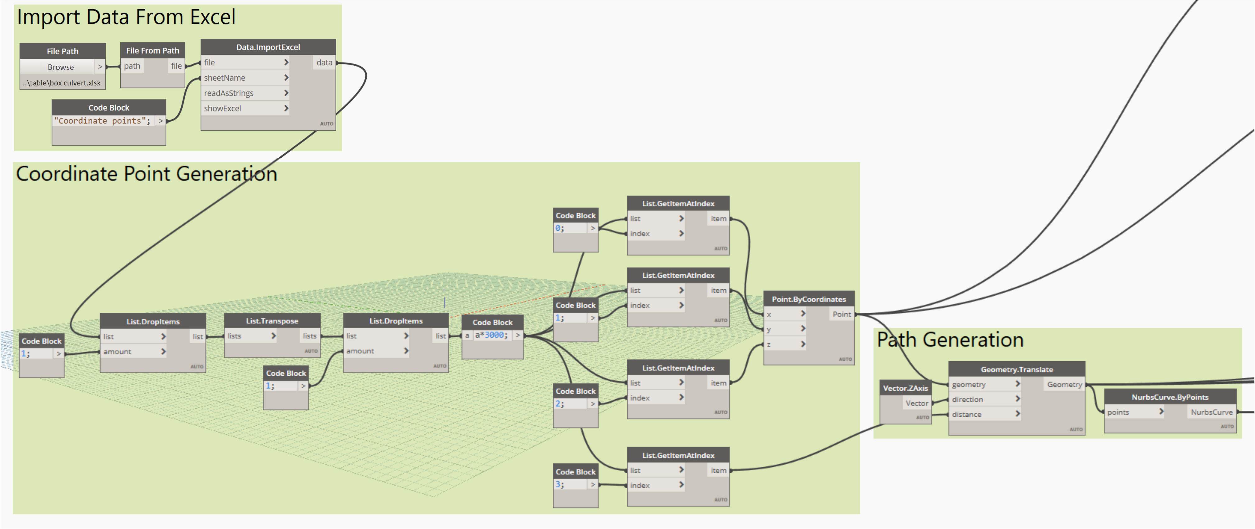
The box culvert layout plan contains the x- and y-coordinate values of the centerline of the box culvert, and the z-coordinate value can be read from the longitudinal section layout plan. These coordinates are compiled in Excel and then imported into Dynamo to generate specific coordinate points. By connecting these points, the culvert centerline can be created. The node used for the generation of the centerline is illustrated in
Figure 2.
Data recorded in a spreadsheet are imported into Dynamo using the Data.ImportExcel node. Specifically, the file path node is employed to read the Excel file path, and the worksheet name of the file is input using the String node. Following import, the data in the table undergo processing to filter out text information, such as titles and sequence numbers, retaining only the x-, y-, and z-coordinate values. Coordinate points are generated using the Point.ByCoordinates node, and these points are translated based on various elevation values with the assistance of the Geometry.Translate node. Ultimately, the box culvert centerline is produced using the NurbsCurve.ByPoints node.
2.1.2. Creation of Box Culvert Cross-Section Profile Family
Within Revit, the ‘Metric Generic Model’ family template is selected, and specific geometric information is utilized as modeling parameters to create the box culvert cross-section profile family. Taking the Autodesk Revit family as an example, the specific modeling steps include (1) setting the layout reference plane in the ‘Family’ editor; (2) adding model dimension annotations and labels according to the characteristics of the drawings; (3) drawing geometric figures and locking them to the reference plane; and (4) setting ‘Family’ properties, including parameter naming, parameter units, etc.
2.1.3. Establishment of Parametric Model of Box Culvert
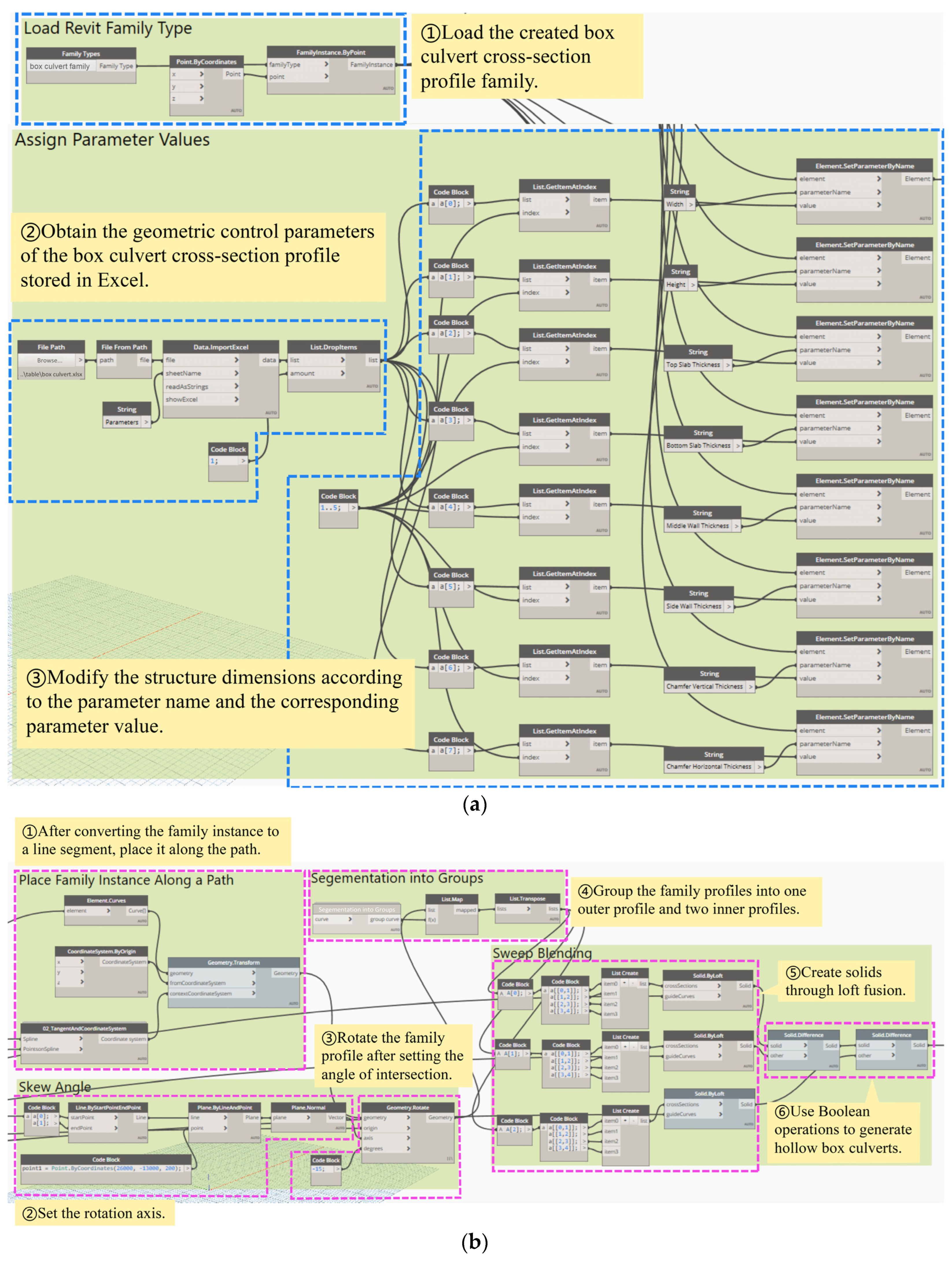
The box culvert cross-section profile family is loaded into Dynamo, and the FamilyInstance.ByPoint node is used to provisionally position the family at the origin.
Specific geometric control parameters of the box culvert cross-section profile are stored in Excel and imported using the Data.ImportExcel node. The Element.SetParameterByName node is employed to input the parameter name and the corresponding data, facilitating modifications to the structural size information and the automatic parametric generation of corresponding cross-sections.
A coordinate system, with the tangent direction of the box culvert centerline as the z-axis, is created using the TangentAndCoordinateSystem node. The Geometry.Transform node then repositions the family profile from the origin to this new coordinate system, effectively positioning the family profile on the box culvert centerline.
Based on the Geometry.Rotate node, the axis of rotation is the normal vector of the plane where the path is located (the plane of the box culvert). Each family profile is rotated around its respective path point by the required intersecting angle, achieving the creation of box culverts with any angle of intersection.
The Element.Curves node transforms the box culvert cross-section profile family into curves, which are independent line segments composing the box culvert cross-section. The PolyCurve.ByJoinedCurves node is then used to merge these segments into closed profile lines of the cross-section. Using the Solid.ByLoft node, inner and outer solids are lofted, and a hollow box culvert structural entity is generated by applying the Solid.Difference node, which is used to create a Boolean difference between the outer and inner profile entities. These nodes are illustrated in
Figure 3.
Upon completion of the box culvert structural entity, it is necessary to load it into the Revit project file as a family. This process is executed using the “Springs.FamilyInstance.ByGeometry” node, which is part of the “Springs” extension package. Following the customization of parameters such as family type and name, the structural entity is exported into the project file. It is crucial to note that the node chain should be set to ‘Longest’. The output node is depicted in
Figure 4.
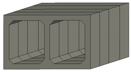
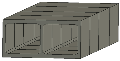
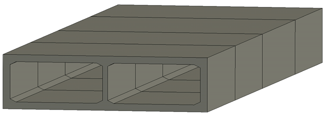
As shown in
Table 1, although box culvert cross-section dimensions are typically fixed, with no variations in their cross-sectional areas, this approach is particularly effective for rapidly constructing box culvert models for varying projects with different sizes, hole numbers, and intersection angles. By merely altering the box culvert cross-section profile family and compiling the corresponding cross-sectional parameters into an Excel sheet, the data in Excel can be processed in Dynamo to swiftly generate the appropriate box culvert model, thereby significantly enhancing modeling efficiency.
2.2. Box Culvert Structural Analysis and Stress Visualization Method
One of the most essential steps in the structural design process is the mechanical calculation and analysis of the structural model. The support of BIM technology during this step plays an important role in connecting the data and in information integration and sharing between the whole structural design stage and other upstream and downstream disciplines [
37]. In this section, we first investigate a method for rapid conversion from a BIM model to a finite element model for computational analysis. Subsequently, we explore the method of directly reflecting the finite element calculation results in the BIM model so as to realize the visualization of the internal forces of the model in the BIM environment.
2.2.1. Box Culvert Model Data Conversion Based on BIM and Midas
The .mct format is a parametric expression used by Midas for structural calculation models. It is a unique document format that can be recognized by Midas. There are three methods for the software to pick up this document format: (1) directly pasting data from other documents into the .mct document of the active project; (2) manually creating model data in the .mct document of the active project; and (3) changing the suffix of the data document to .mct and then directly accessing the .mct document in the active project.
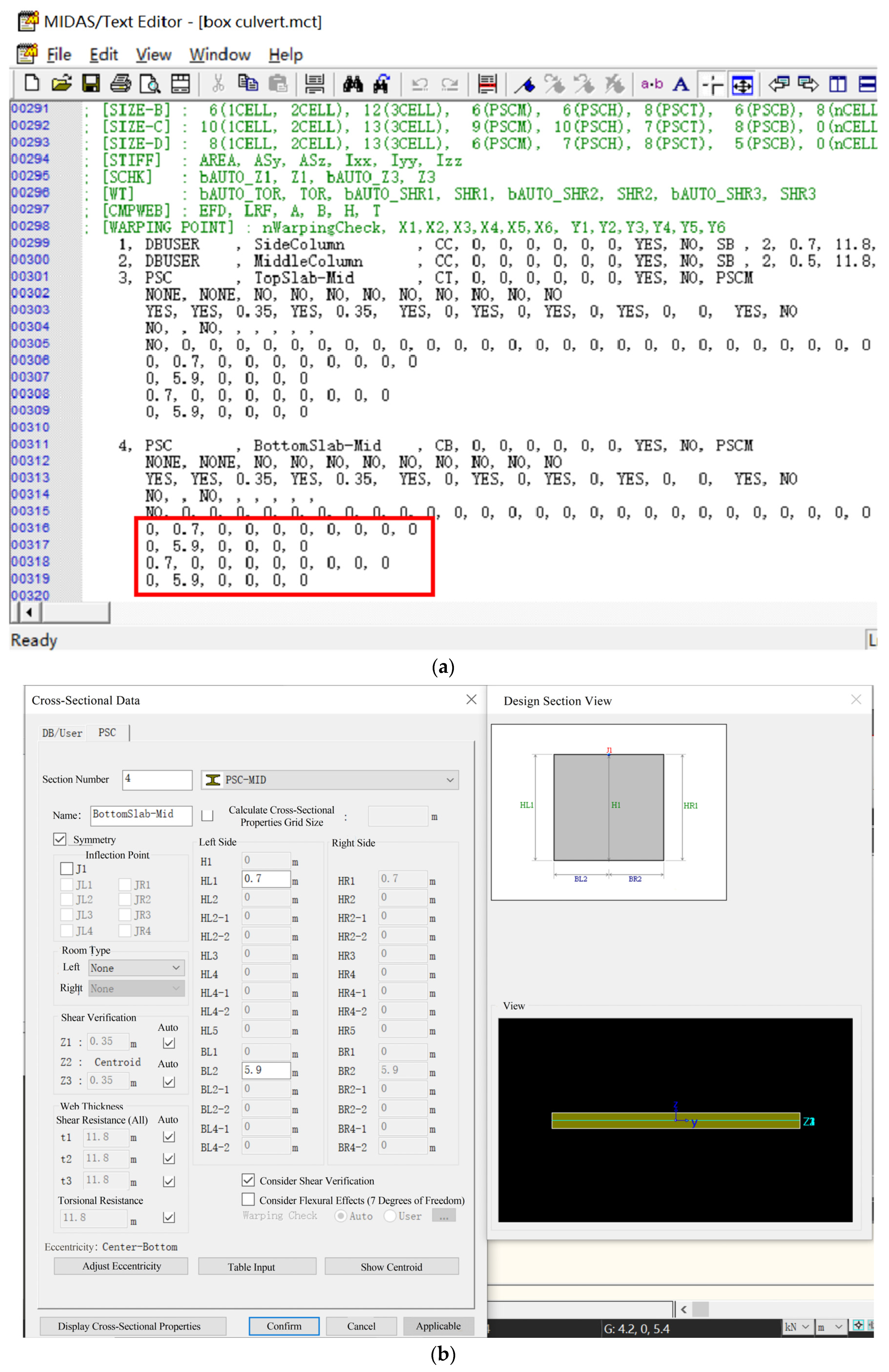
To clarify the relationship between the actual meanings of data within the information flow of MCT documents and the data of model parameters,
Figure 5 illustrates the correspondence. It shows the MCT file data for the bottom slab (mid-span) section design of the baseplate in Midas Civil, along with the section setting interface and a schematic of the section data. It is evident from the MCT information flow that the sectional parameters correspond directly to the displayed data, excluding the fixed format statements.
Based on the analysis above, we opted for the third method. The precise implementation process is as follows: Using the Dynamo visual programming tool, the design model’s data (geometric and material parameters) are exported in the document format recognized by Midas Civil. They are then converted to an .mct file extension for direct importation into Midas Civil. This achieves data conversion from BIM to Midas, completing the research and development of the data transformation process.
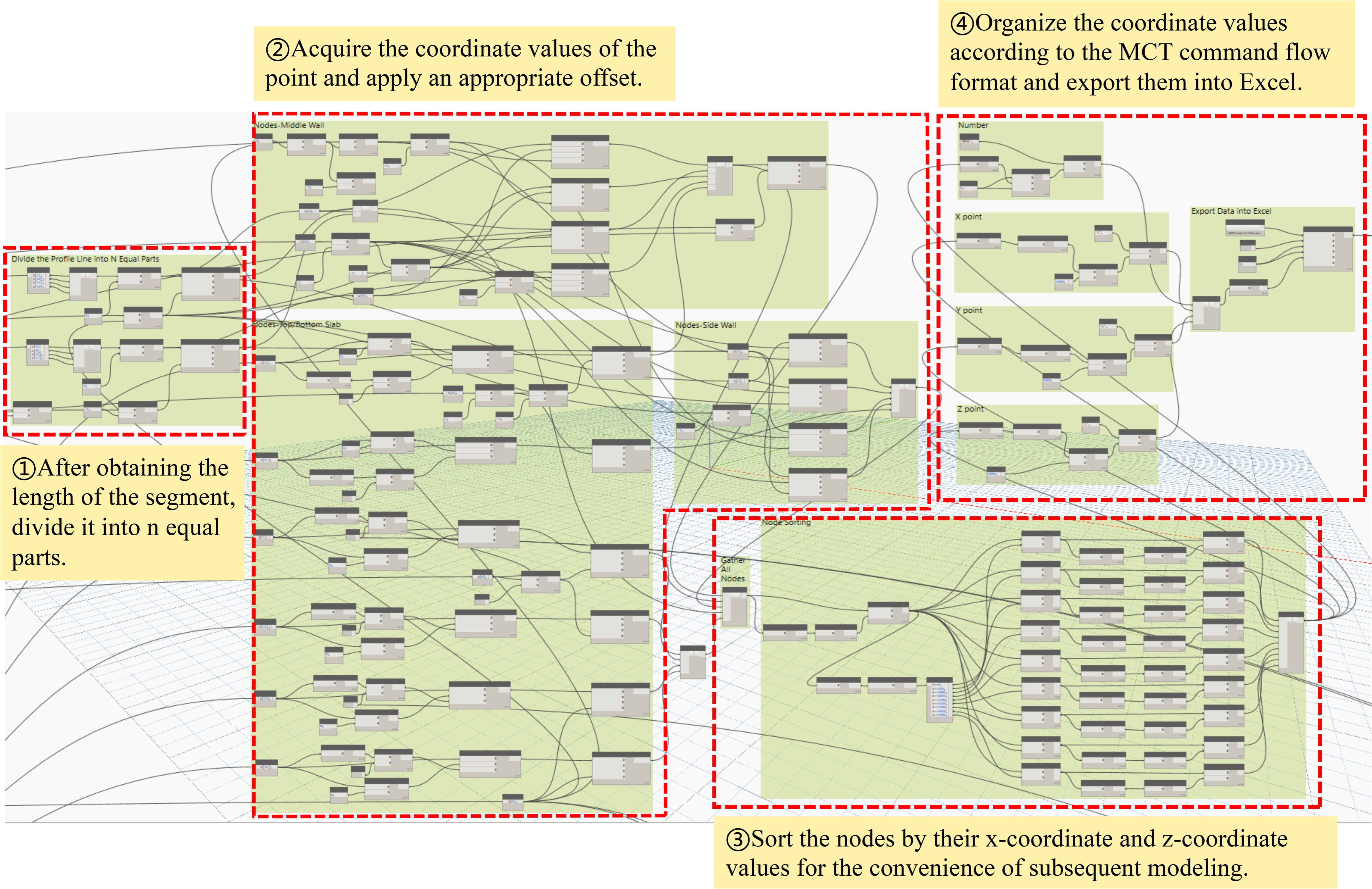
(1) Information Exchange: The initial step in obtaining nodes involves acquiring the segmented lines of the family outline. The lengths of these segments are determined using the “Curve.Length” node. Then, the “Curve.PointsAtSegmentLengthFromPoint” node is used to divide each segment into ‘n’ equal parts. The exact division is determined based on the required lengths of the individual elements within Midas. After the division, the coordinates of each point are obtained. A subset of these points, particularly those associated with the top slab, bottom slab, side walls, and center partition wall, are then offset based on geometric relations using the “Geometry.Translate” node. Subsequent to this, a verification is conducted to ensure the completeness of node acquisition, with additional points being supplemented individually, such as those at the haunches, and their coordinates are recorded. Following this, the data format of the .mct command flow is used as a template, and with the assistance of Dynamo’s list manipulation capabilities, the data are structured accordingly. Ultimately, the “Data.ExportExcel” node is employed to export the data into an Excel template.
Figure 6 illustrates the Dynamo program for node acquisition.
The structural parameters required for the section command include the thicknesses of the top slab, bottom slab, side walls, and middle partition walls, as well as the culvert length. These parameters are obtained using the “Element.GetParameterValueByName” node, which extracts the necessary structural parameter values. It is essential to differentiate between the corresponding section characteristic types, section eccentric positions, and section shapes. Following the format of the .mct command flow data, the data are organized using Dynamo’s list editing capabilities. Once the data are structured, they are imported into Excel for storage. Since the nodes in the section command are connected to the structural parameters of the box culvert, the geometry of the box culvert finite element model can be updated as the structural parameters of the box culvert BIM model change.
Figure 7 depicts a section of the Dynamo program used for section acquisition.
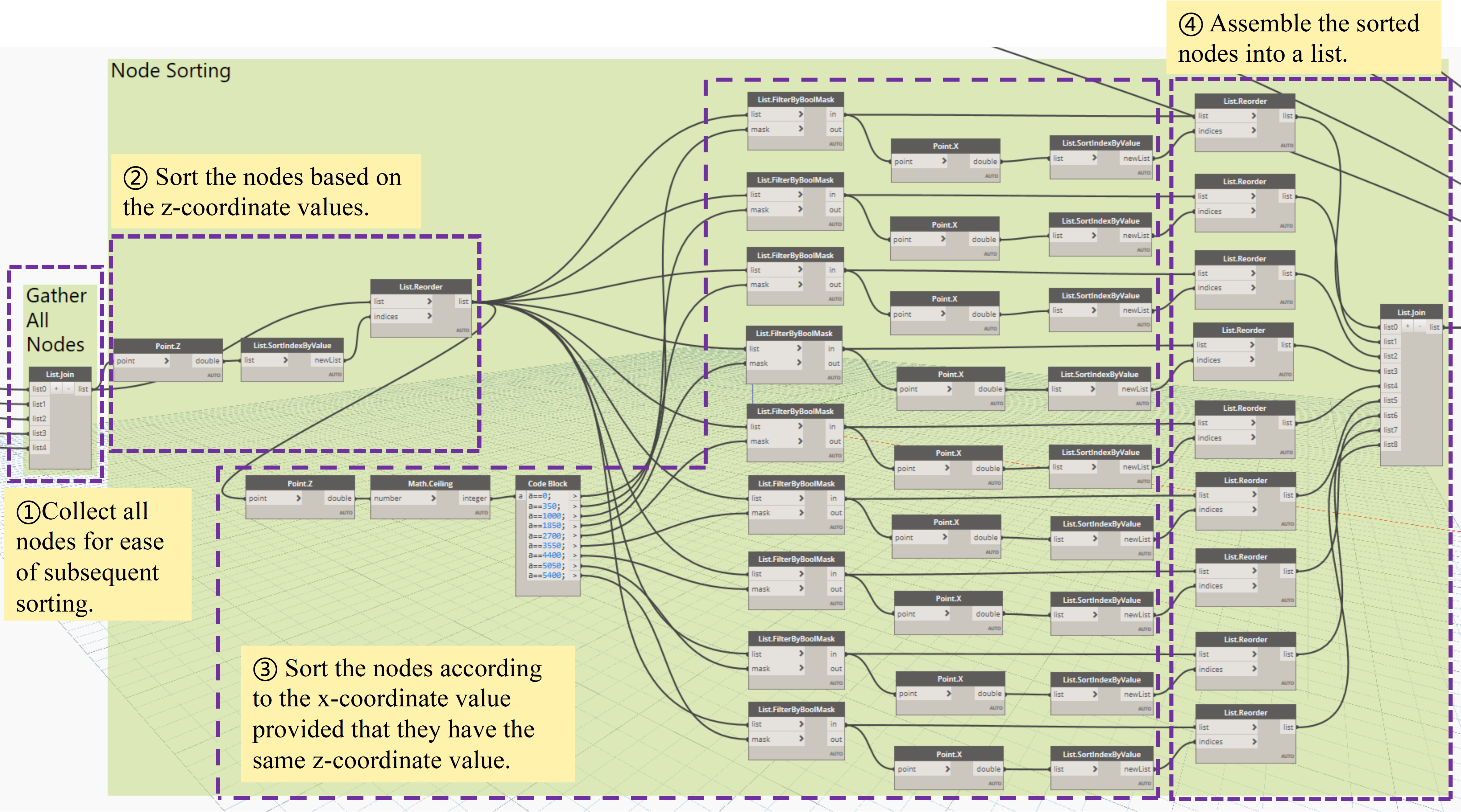
In Midas Civil, the establishment of elements is accomplished by connecting nodes; therefore, to better discern the relationship between elements and nodes, it is advisable to perform node sorting. Nodes are arranged according to the Cartesian coordinate system, and this process is also executed through Dynamo. The sorting rationale involves utilizing the “List.FilterByBoolMask” node to filter points with identical z-coordinate values and then retrieving the x-coordinate values. The nodes are sorted by their x-coordinates using the “List.SortIndexByValue” node, which returns the corresponding index values. The “List.Reorder” node is then used to reorder the input list based on the provided index list, thereby accomplishing the sorting of nodes. The specific node-sorting Dynamo program is depicted in
Figure 8.
Nodes that have been sorted are divided into three parts: mid-span units for the top and bottom slabs; support and mid-span units for the top and bottom slabs with variable cross-section elements; and the middle columns of the side columns. After assigning material and section numbers, the information is formatted according to the MCT command stream data format and then exported to Excel.
Figure 9 presents a segment of the Dynamo program utilized for element acquisition.
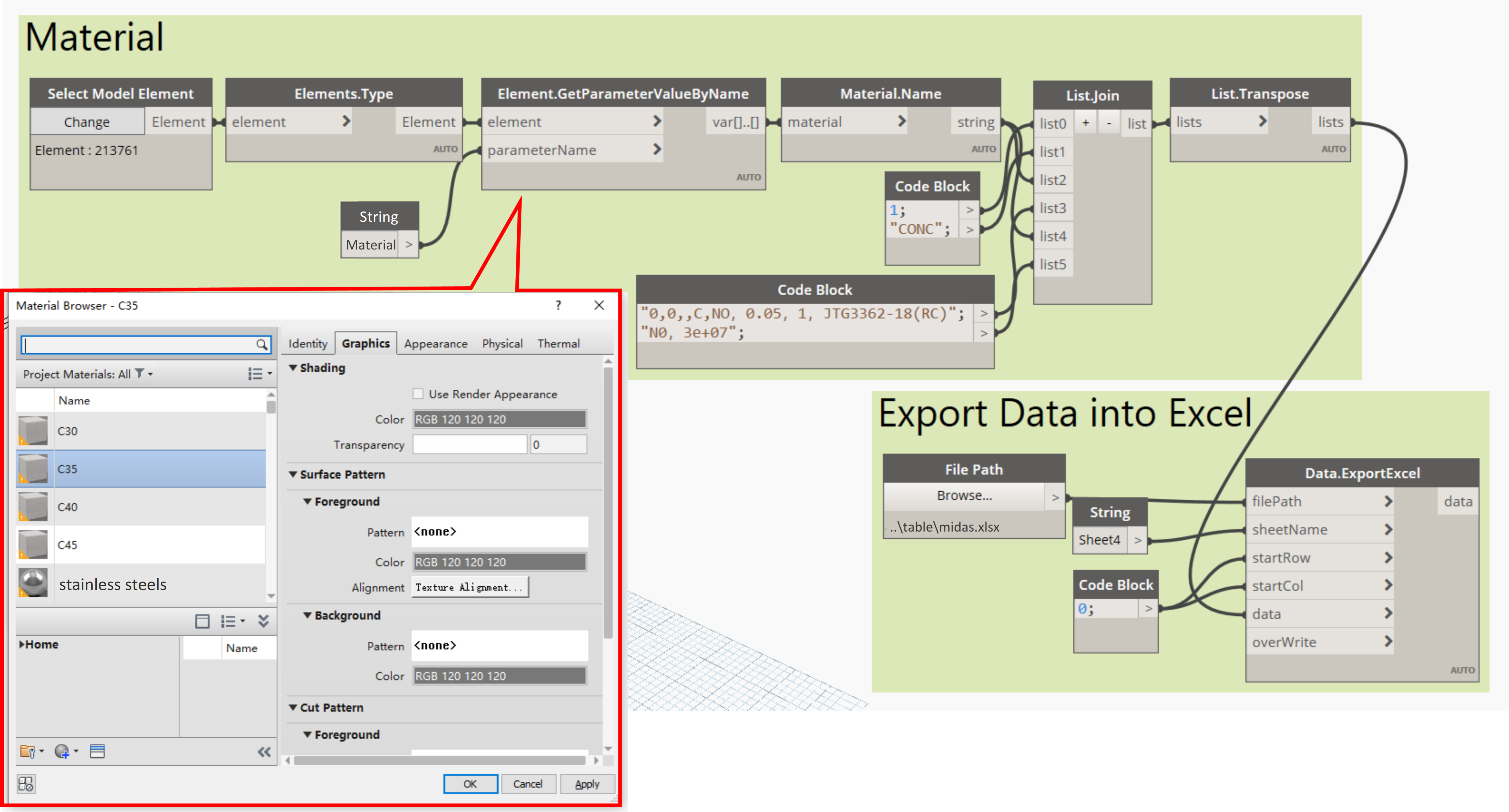
Material properties can be assigned to family components in Revit by setting the relevant material attributes as type parameters. Dynamo is used to extract the material information from the family components, ensuring that any subsequent changes to the material properties are captured by the program. The acquired data are organized according to the data format of the MCT command flow and then exported to Excel. The specific Dynamo program for material acquisition is shown in
Figure 10.
(2) File Conversion: The content of the MCT command flow was previously stored in an Excel file. This Excel file must be converted into an .mct file, a process that is executed using C#. The specific steps involved are as follows: (1) Change the file extension of the .xlsx file to .txt. (2) Remove non-essential header rows such as sequence numbers and section names. (3) Insert the corresponding command at the beginning of the file. (4) Replace all spaces between data with commas. (5) Save the file and change the file extension to .mct.
Upon completion of these steps, an MCT file can be generated with a single click. Subsequently, within the Midas Civil software, one can navigate to “Tools”, click on “MCT Command Window”, and open the corresponding .mct file to complete the creation of the finite element model. This process facilitates the importation of a parametric box culvert model from BIM into Midas Civil, enabling further structural analysis.
(3) Finite Element Structural Analysis: The model serves as a vehicle for structural computations, necessitating the establishment of boundary conditions, the application of loads, and the delineation of construction stages. After these conditions are set, the program is executed to carry out finite element structural analysis.
2.2.2. Visualization of Internal Forces in Box Culvert Model Based on BIM and Midas
FEA effectively captures the values of internal forces within sections, and these values can provide an intuitive representation of the stress states in structural components, thereby facilitating the assessment of their safety conditions. In alignment with the objective of guiding construction, it is imperative that the computational results are presented to designers and construction personnel efficiently and intuitively [
38,
39,
40]. The learning curve for finite element software operation is steep, creating a disconnect with practical application. To address this issue and enhance the information capacity and integration of BIM models, a method based on Dynamo was proposed to feed FEA results back into the BIM environment, thus realizing the visualization of internal forces in box culvert structures.
Revit offers tools for an analytical visualization framework with the function of replacing traditional, redundant data visualization processes. It enables the direct display of computational analysis results within the Revit project environment, streamlining the analysis process and avoiding compatibility issues with data transfer between different software applications. Currently, the analytical visualization framework can be utilized to create colored surfaces, markers with text, diagrams with text, vectors with text, and deformed shapes.
In this study, the visualization of internal forces in culvert structures is achieved through programming in Dynamo software. The specific steps are as follows:
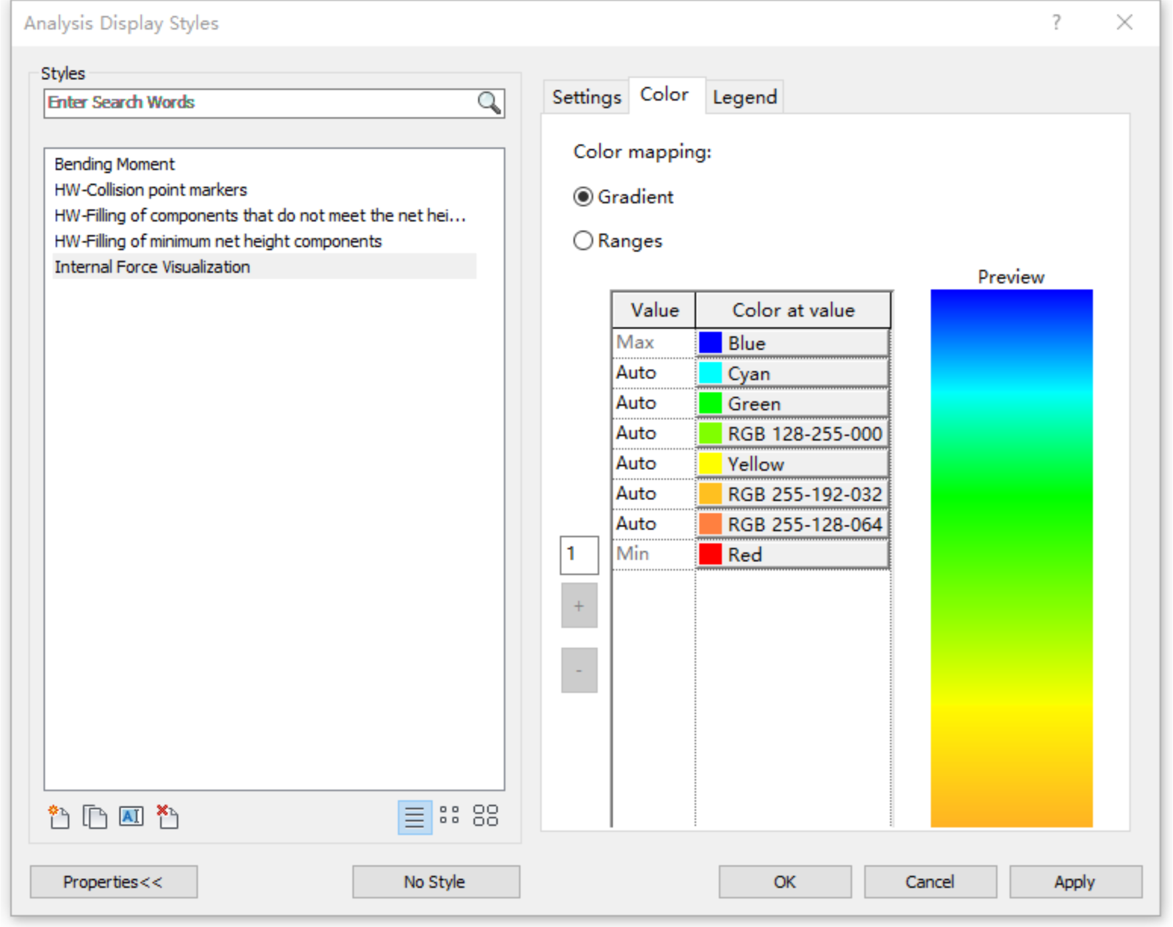
Step 1: Creation of Analysis Display Style. An analysis display style named “Internal Force Visualization” is established, as depicted in
Figure 11. This style utilizes a gradient mode with no defined threshold. When new value–color pairs are added to the default maximum and minimum settings, the automatically assigned colors are interpolated between the colors above and below them (using a linear RGB interpolation). The precise numerical values corresponding to the “automatic” values vary in accordance with the analysis results.
Step 2: Acquisition of Visualization Space Analysis Manager. The representation method for the analysis results is configured, and the Legend Setting node is used to set the related legend information, including display units, display names, text types, and legend dimensions, to elucidate the meaning of the internal force values represented by colors, as illustrated in
Figure 12.
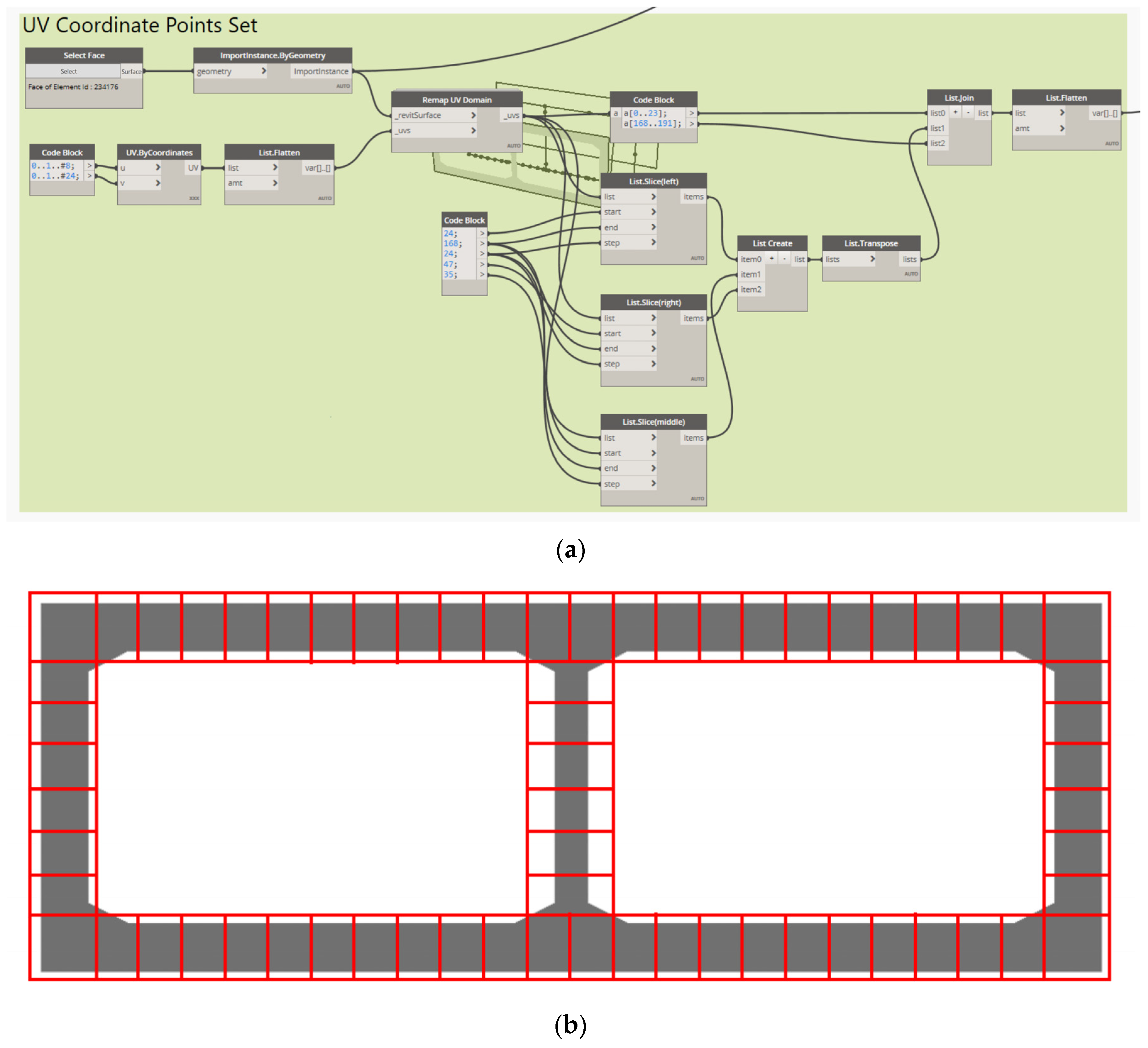
Step 3: Creation of Analysis Result Data. A colored-surface-based visualization mode is employed to exhibit the internal force analysis results. Initially, a specific surface, which acts as a visualization medium, is associated. The BoundingBoxUV of this surface is obtained and then segmented according to the arrangement of the internal force measurement points, as illustrated in
Figure 13. Post-cutting, each segment is utilized to exhibit the analysis results of the corresponding internal force measurement points.
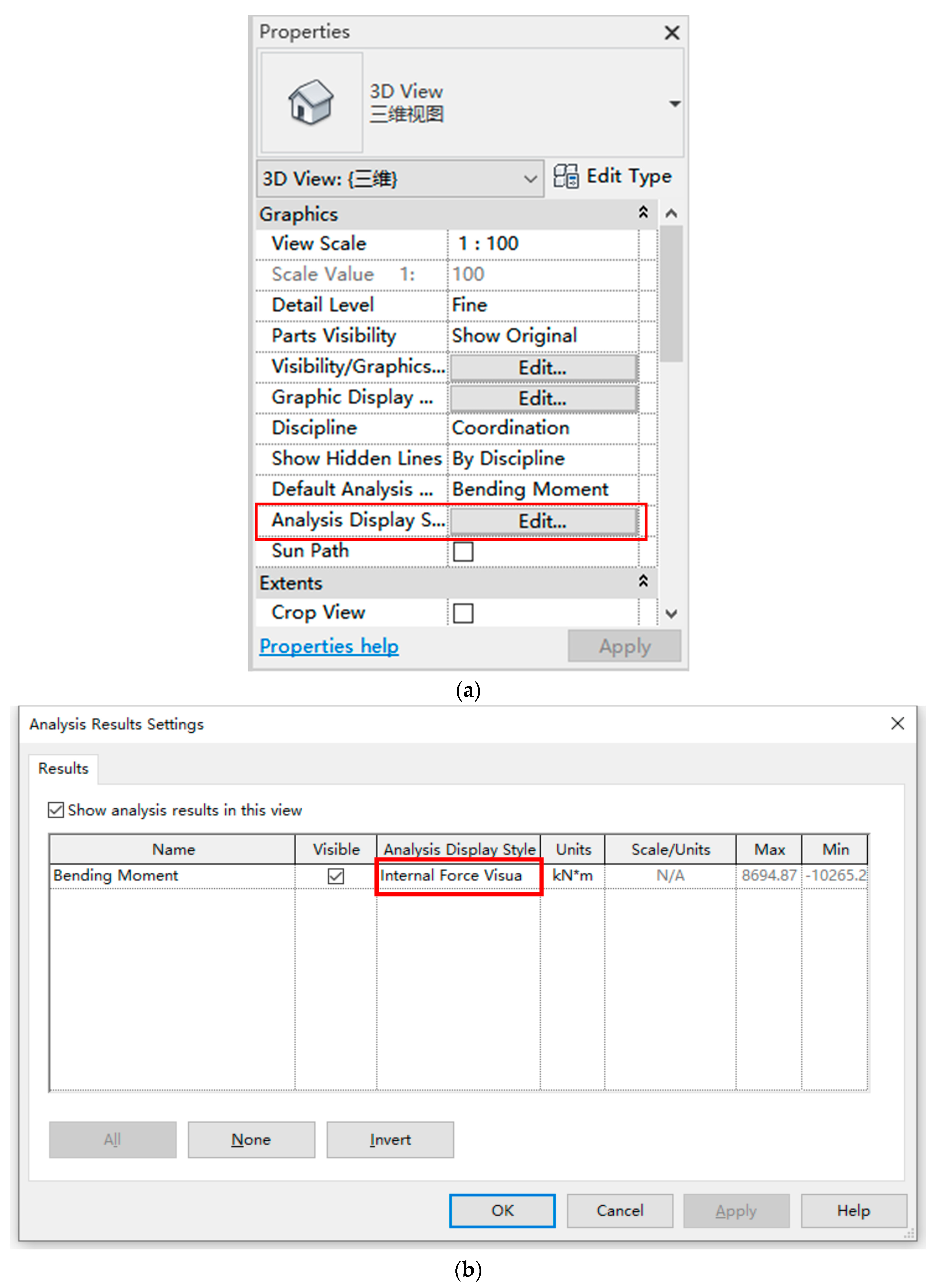
Step 4: Updating Spatial Analysis and Setting View Analysis Display Style. The internal force calculation results from Midas Civil are exported to Excel. Dynamo is then utilized to acquire and organize the data in the table. These data are combined with the previously acquired coordinates of the associated surface UV domains. The Colored Surface Display Style node from the archi-lab package is used to update the spatial analysis results. In order to apply the analysis display style to the view, the current view’s analysis display settings must be configured to the predefined analysis display style, as shown in
Figure 14.
3. Case Study
3.1. Project Background
In a certain urban expressway, a box culvert passing beneath a highway is precast in four segments. The box culvert spans an overall length of 41.5 m and employs a design consisting of a two-chamber, non-pressurized box culvert, with each chamber measuring 15.9 m in width and 5.4 m in height. The culvert stands at an overall height of 5.4 m and is embedded 1.5 m underground. The physical dimensions of the culvert structure are as follows: the top and bottom slabs each have a thickness of 0.7 m, the central wall is 0.5 m thick, the side walls have a thickness of 0.7 m, and the edges of the culvert are chamfered with dimensions of 0.6 m by 0.3 m.
3.2. Parametric BIM Model of the Box Culvert
In Revit, based on the method described in
Section 4, a box culvert model was developed utilizing Dynamo node programming.
Step 1: Formulate Box Culvert’s Centerline
Adopting the principle of connecting dots to institute a line, the centerline of the culvert was concocted after acquiring the culvert’s center point.
Step 2: Construct Box Culvert Profile Family
Eight geometrical details—the width, height, top slab thickness, bottom slab thickness, sidewall thickness, middle wall thickness, chamfer horizontal thickness, and chamfer vertical thickness—were employed as modeling parameters to construct the box culvert cross-sectional profile family. The cross-sectional profile family is shown in
Figure 15.
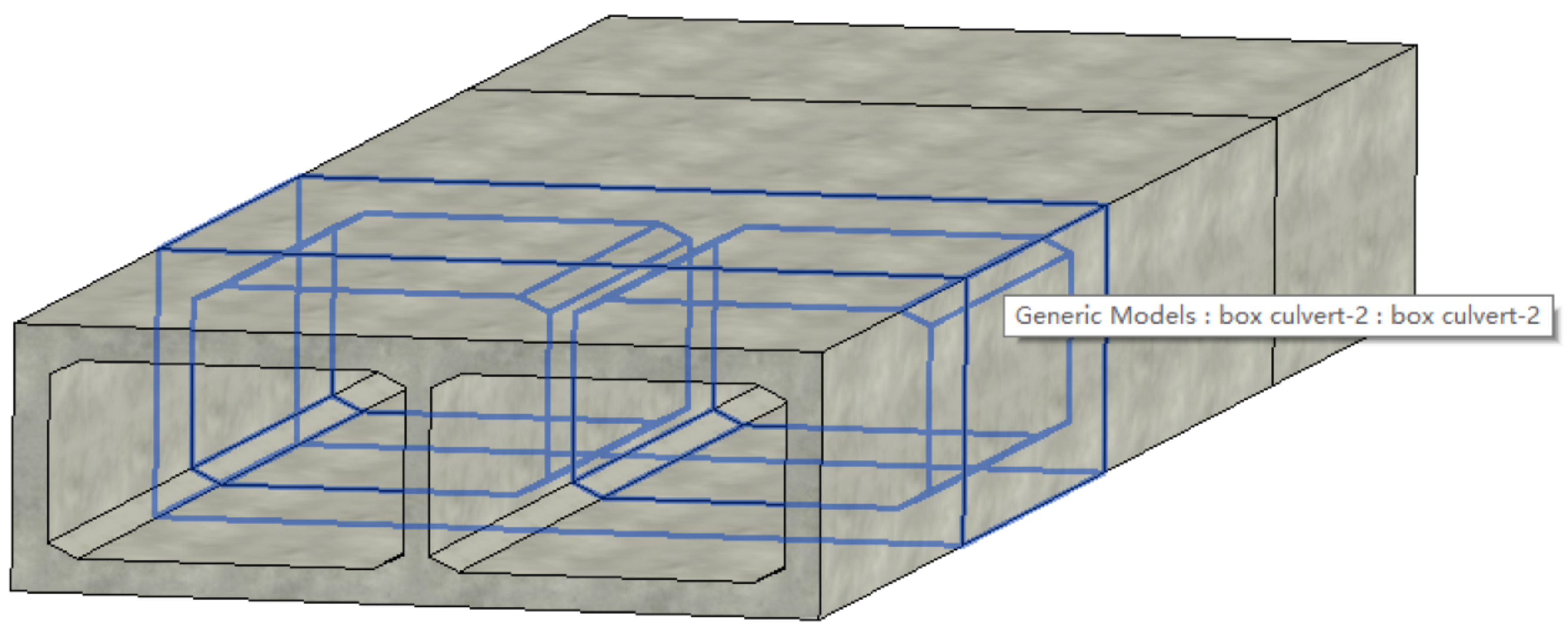
Step 3: Create Box Culvert BIM Model
The interior and exterior profile lines of the section were selected, and through lofting fusion, one solid exterior profile and two solid interior profiles were generated. Employing the Boolean difference operation between the two entities, two hollow interior profiles were sequentially formed, constructing the box culvert. The box culvert BIM model is depicted in
Figure 16.
3.3. BIM–Midas-Based Verification of Box Culvert Structure
Structural calculation is one of the key processes in box culvert design. Utilizing finite element simulation analysis generates theoretical values for the structural stress and deformation of a box culvert. These calculated values not only assure structural safety during the design phase but also serve as a guide for maintaining quality and safety measures during construction.
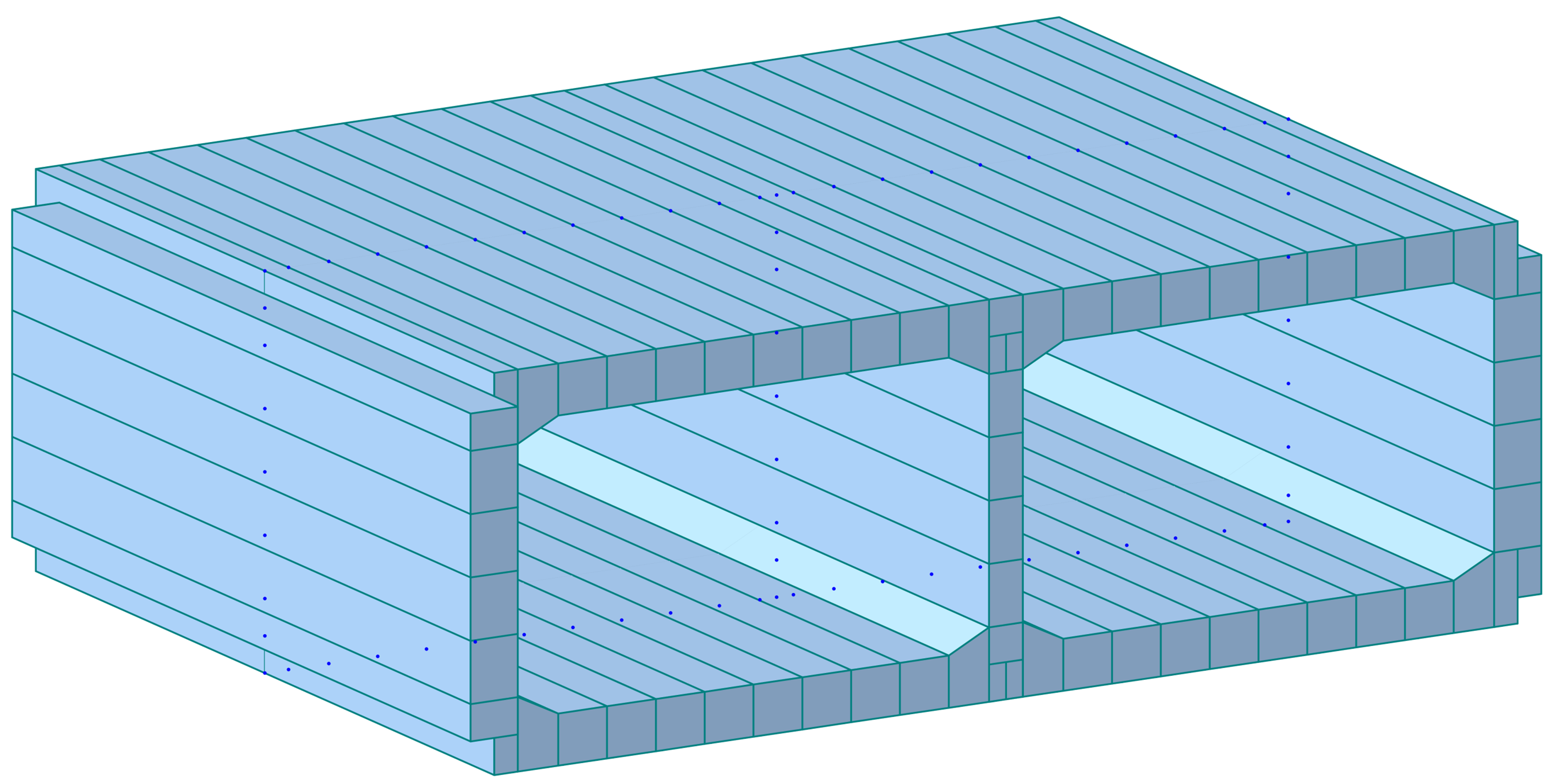
Step 1: Conversion to Box Culvert Finite Element Model
On the basis of the model established in the previous section, we continued to run the Dynamo node program according to the method described in
Section 2.2.1 to enable the BIM model to generate the Midas finite element model in one click with the assistance of information flow by converting to an .mct file. Taking the second section of the box culvert as an example, the conversion result in Midas Civil is illustrated in
Figure 17.
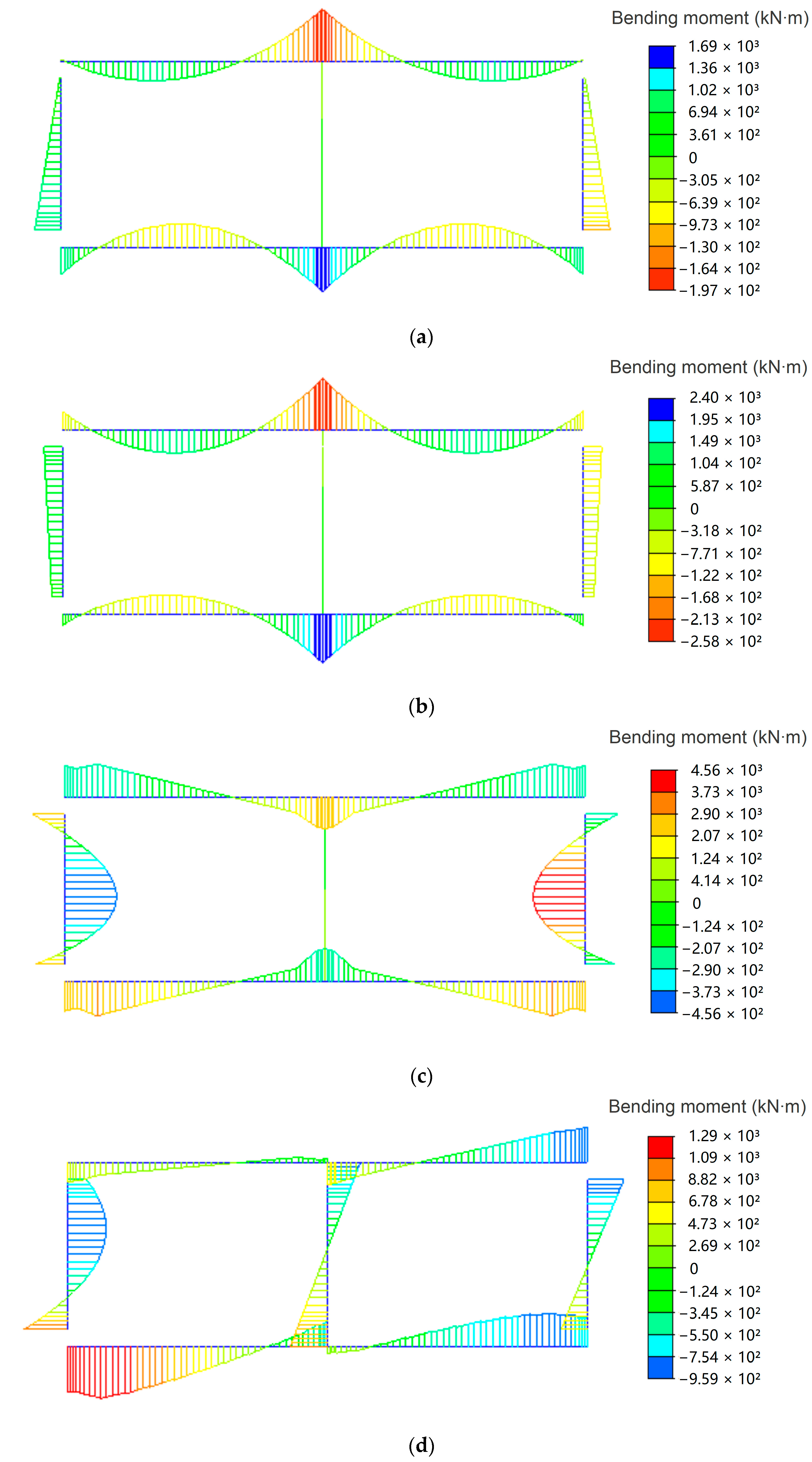
Step 2: Internal Force Analysis of Box Culvert Finite Element Model
The box culvert was simulated using beam elements with the properties of C35 concrete material. In the model, except for the position of the intersection between the middle web and the bottom plate, which was considered a consolidation, the other bottom plate units were simulated as elastic connections connected with the foundation. The main loads considered in the calculation and analysis of the box culvert were self-weight, vertical overburden pressure, lateral earth pressure, vehicle load (excluding impact force), and additional earth pressure caused by vehicle load.
After establishing boundary conditions and implementing loads, the software was executed to carry out an FEA on the box culvert.
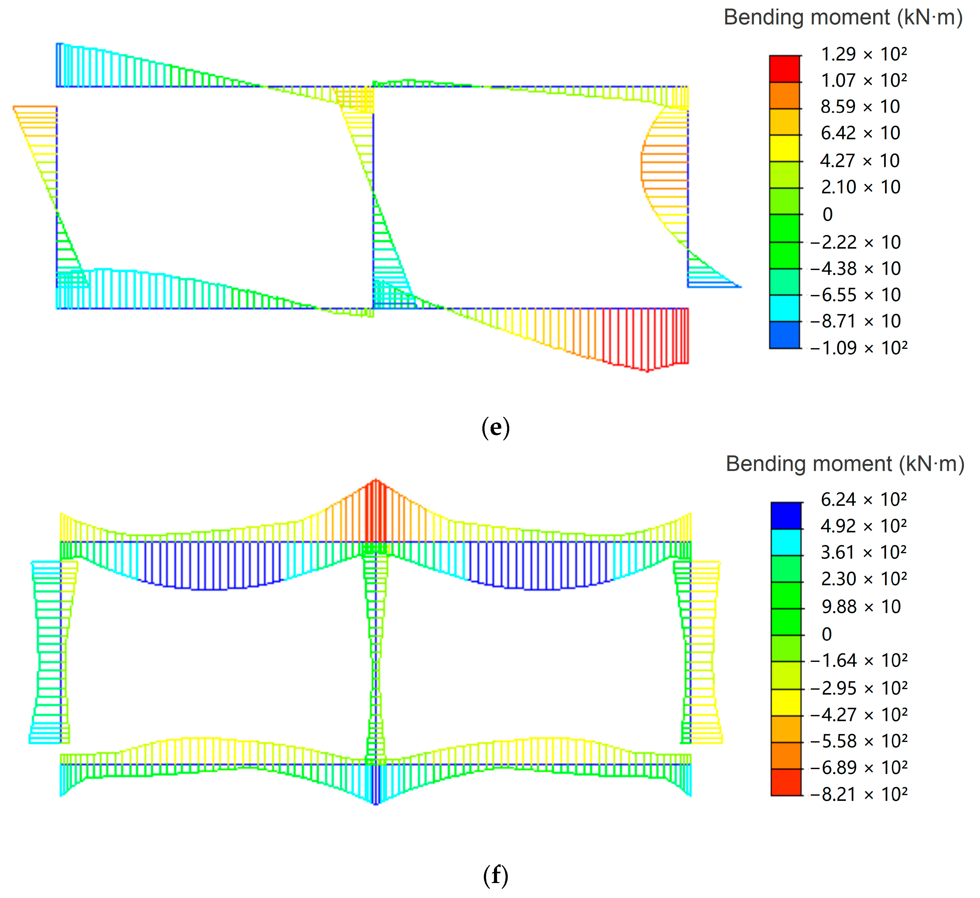
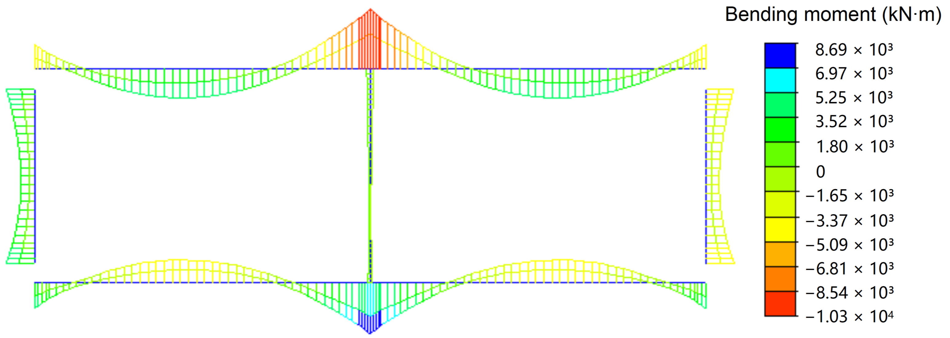
Figure 18 depicts internal force diagrams representing the bending moments of the box culvert under various working conditions. In particular, the bending moment envelope under the load-bearing capacity limit state of the box culvert is illustrated in
Figure 19. A summary of the maximum bending moment values of the corresponding control sections is presented in
Table 2.
As shown in
Figure 19 and
Table 2, the maximum negative bending moment of the box culvert’s top slab was −10,265.23 kN∙m, and the maximum positive bending moment was 4813.96 kN∙m. For the bottom slab, the maximum negative bending moment was −8694.87 kN∙m, and the maximum positive bending moment was 3996.91 kN∙m. Given the symmetry of the double-chambered box culvert structure and the boundary conditions, the bending moment distribution was also symmetrical under symmetrical loads. In accordance with the principles of structural mechanics, these results align with the actual scenarios. In conclusion, the finite element model is capable of effectively simulating the concrete box culvert structure, accurately reflecting the characteristics of the structural stress response.
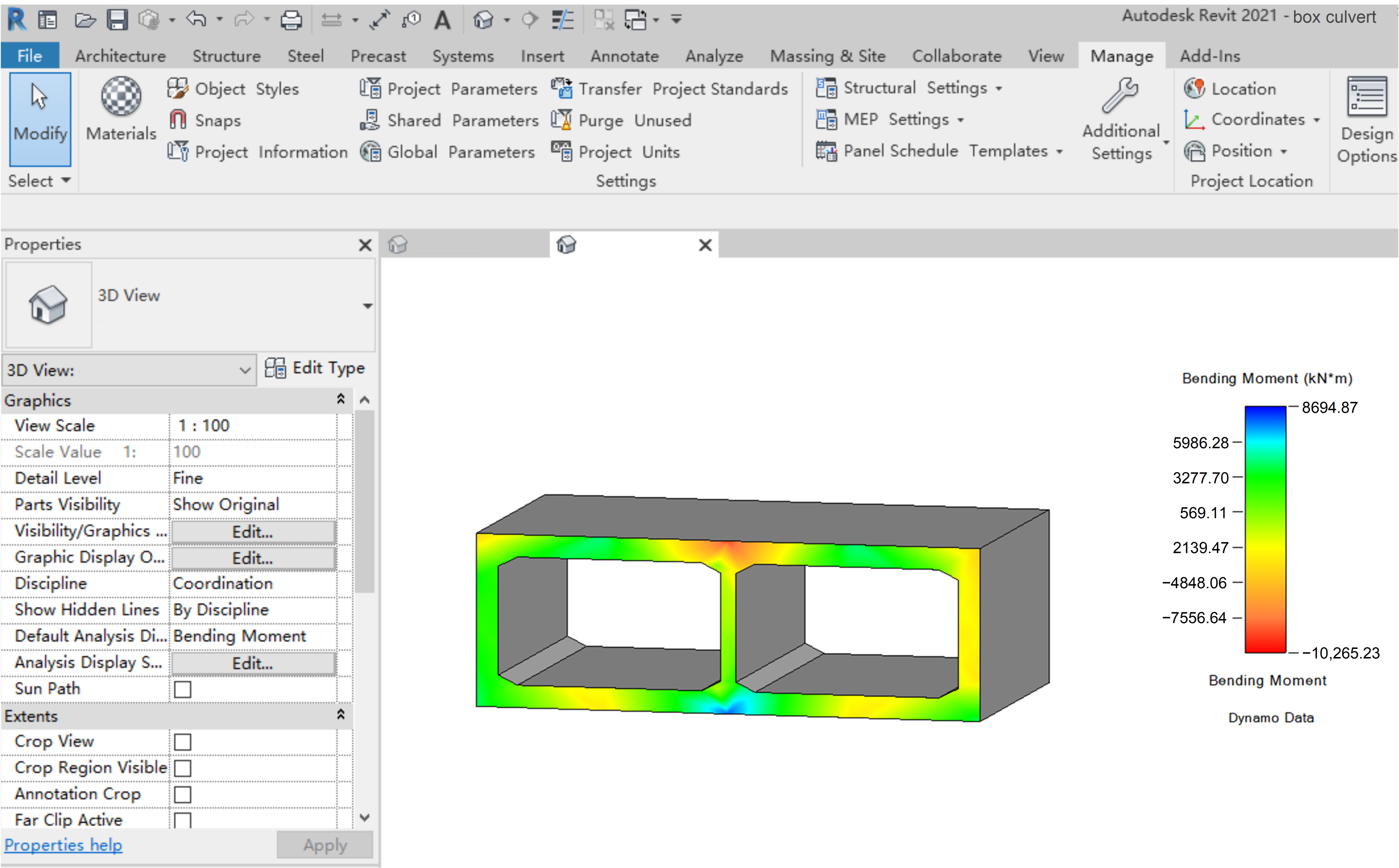
Step 3: Visualization of Internal Forces in Box Culvert BIM Model
The above FEA internal force results were exported from Midas Civil to Excel for storage. Following the method described in
Section 2.2.2, the “Internal Force Visualization” display style was established, the legend style was set, and the UV coordinate values of the stress points were determined. The internal force results data stored in Excel were extracted and processed to align with the corresponding stress measurement locations. The ‘Colored Surface Display Style’ node in Dynamo was employed to achieve the visualization of the box culvert model’s internal forces. Taking the second section of the box culvert as an example,
Figure 20 presents the distribution of bending moments in the box culvert BIM model under the fundamental combination. Design engineers and construction personnel can access computational analysis results within the BIM environment, which decreases time expenditure and offers theoretical backing for their tasks, thereby capitalizing on the multi-use efficiency of BIM and actualizing the value of BIM for information sharing and data integration.
4. Discussion
This paper presents a BIM parametric modeling methodology for box culverts, enabling the automatic generation of BIM culvert models. Its core advantage lies in its powerful parametric capabilities and high adaptability and flexibility. By incorporating a multitude of adjustable parameters, it can quickly generate box culvert models of various sizes with different numbers of holes and different intersection angles, thus significantly enhancing modeling efficiency.
In terms of the integration of BIM and FEA, this study advances the automation of the structural analysis of box culverts. By developing the conversion between the box culvert BIM model and the finite element model, it facilitates the FEA of box culverts of existing BIM models for engineers, significantly reduces the workload caused by repeated modeling, and offers new insights and methods for the effective integration of BIM technology and FEA technology in the field of culvert engineering.
Furthermore, this study promotes BIM technology integration by displaying the results of finite element structural analysis directly on the BIM model. This means that once a structural analysis is completed, the analysis results can be quickly mapped back to the BIM model for intuitive visualization of the internal force distribution. This approach enhances the interaction between design and analysis, allowing engineers and designers to gain a deeper understanding of structural behavior through enhanced visual feedback in the BIM environment.
Although this study made significant progress in the automated generation of BIM for box culverts, finite element model conversion, and internal force visualization, demonstrating great potential for broad application in underground engineering design, there is a clear need for further research and improvement related to the following aspects: First, the current modeling method primarily focuses on box culverts. Parametric modeling has not yet been carried out for other crucial components in culvert engineering, such as wing walls, wing wall foundations, inlet and outlet structures, manhole pads, coping stones, cones, and drainage beds. Future research should be extended to the parametric modeling of these components. Second, the method of obtaining and transmitting data, such as boundary conditions and loading parameters, during the model conversion process should be further improved, and a more efficient and comprehensive program for BIM model to finite element model conversion will be developed. Lastly, regarding the visualization of internal forces in the Revit project environment, the current achievements are limited to two-dimensional representations on a single plane, without a comprehensive visualization of the three-dimensional internal force state. Future work should move in this direction to provide a more comprehensive analytical perspective for engineering personnel.


