Review

A Review of Friction Dissipative Beam-to-Column Connections for the Seismic Design of MRFs

Department of Engineering, University of Palermo, 90128 Palermo, Italy
*
Authors to whom correspondence should be addressed.
Appl. Sci. 2024, 14(6), 2291; https://doi.org/10.3390/app14062291
Submission received: 22 December 2023 / Revised: 22 February 2024 / Accepted: 2 March 2024 / Published: 8 March 2024
(This article belongs to the Special Issue Feature Review Papers in Applied Physics)

Abstract

:
The use of friction-based beam-to-column connections (BCCs) for earthquake-resistant moment-resistant frames (MRFs), aimed at eliminating damage to beam end sections due to the development of plastic hinges, has been prevalent since the early 1980s. Different technical solutions have been proposed for steel structures, and some have been designed for timber structures, while a few recent studies concern friction joints employed in reinforced concrete structures. Research aimed at characterizing the behavior of joints has focused on the evaluation of the tribological properties of the friction materials, coefficient of friction, shape and stability of the hysteresis cycles, influence of the temperature, speed of load application, effects of the application method, stability of preload, the influence of seismic excitation characteristics on the structural response, statistical characterization of amplitude, and frequency of the slip excursion during seismic excitation. Studies aimed at identifying the design parameters capable of optimizing performance have focused attention mainly on the slip threshold, device stiffness, and deformation capacity. This review compiles the main and most recent solutions developed for MRFs. Furthermore, the pros and cons for each solution are highlighted, focusing on the dissipative capacity, shape, and stability of hysteresis loops. In addition, the common issues affecting all friction connections, namely the characteristics of friction shims and the role of bolt preload, are discussed. Based on the above considerations, guidelines can be outlined that can be used to help to choose the most appropriate solutions for BCCs for MRFs.

1. Introduction

For many decades, engineers have tried to protect structures from hazardous seismic events by establishing effective design and retrofitting strategies. Housner [1] placed the foundations of seismic design based on the energy balance between the energy transmitted by the earthquake (input energy) and the energy absorbed and dissipated by the structure. In order to reduce the energy transmitted to the structure, seismic isolation devices can be placed at the base of the structure (base isolation system (BIS)) [2], or vibrating barriers (ViBas) can be buried in the soil, detached from surrounding buildings, that exploit the soil structure interaction (SSI) and are able to absorb a large proportion of the seismic energy transferred by the ground motion [3]. Thus, the limitation of the input energy requires complex devices that modify the structural behavior and therefore require advanced design criteria. In more conventional framed system design practice, an appropriate calibration of the overall stiffness and resistance of the structure can allow a modest reduction in input energy [4]. Thus, the most common anti-seismic design techniques are oriented towards providing the structure with characteristics and devices capable of dissipating the energy transmitted with limited damage [5,6]. The main energy dissipation source for standard moment-resisting frames (MRFs), according to the capacity design approach, is to provide plastic hinges at beam-to-column connections (BCCs). To avoid beam end damage, increase the dissipation capacity, and moderate the energy and displacement seismic demand, the use of additional energy dissipation devices inside [7] or outside [8] the structure has been proposed and investigated. Some pioneering designs of braces equipped with friction dampers for seismic response control include the Concordia University library building [9], the seismic rehabilitation of the ten-story Eaton’s building, built in 1925 and retrofitted in 2000, using friction dampers in steel bracings [10], and the most recent application at Torres Cuarzo in Mexico City. The use of bracings with friction dissipative devices for the seismic protection of structures is now common in technical practice; their use in the creation of seismic-resilient nodes is growing rapidly, as demonstrated by the first application of the technology to the design of the eleven-story Bellagio Apartment Building in Taranaki Street, Wellington [11], the Te Puni Village Tower Building of the Victoria University of Wellington student accommodation [12], to more recent ones for the adaptation of existing structures [13], or the retrofitting of the Oxford Terrace in Christchurch (New Zealand) using self-centering and flat-plate friction dampers [14] for connecting the seismic walls to the foundations.
The reason why so many innovative solutions for beam-to-column connections have been developed for steel structures over the last 25 years lies in the poor performance of some of them, as shown during the Northridge (1994) and Kobe (1995) earthquakes. These events were a game-changer for the structural engineering community. As a matter of fact, pre-Northridge beam-to-column connections of steel MRFs were usually realized by welding beam flanges onto the column flanges. The plastic hinge was supposed to form a starting point from the welds connecting the beam and column. This constructional detail led to unpredicted stress concentration, causing numerous premature failures and limited connection ductility. For this reason, all post-Northridge connections have the common goal of avoiding any damage to the elements connecting the beam and column. With regard to energy dissipation, this can be ensured, for instance, by the formation of ordinary plastic hinges in the beam segment, sufficiently distanced by column flanges and characterized by a dogbone section, or by introducing more innovative systems. This type of solution, although limiting fragile breakages due to the presence of welds, does not protect the beam from damage caused by exceeding the elastic limit, allowing a potential accumulation of damage capable of causing the element to collapse due to low-cyclic fatigue. Therefore, solutions that involve the concentration of damage in specifically designed special portions of the beam [15,16,17] or in devices added with the aim of dissipating energy, which was first proposed in the 1970s [7], have become increasingly successful.
Firstly, supplementary energy dissipation devices are grouped into two broad categories: hysteretic devices with displacement-dependent behavior and devices with velocity dependent behavior, such as viscoelastic and fluid viscous ones.
Hysteretic devices with displacement-dependent behavior have been widely studied and adopted in the construction sector, since they appear to be the simpler types of dampers. Their performance is not significantly influenced by the loading amplitude, frequency, or operating temperature and is only influenced to a limited extent by the number of cycles [18,19]. Hysteretic dissipation in the mechanics field can be obtained from two main distinct sources, plastic behavior or friction, namely metallic or friction dampers. It should be noted that several hybrid solutions have been proposed that combine in different ways some of the various dissipation mechanisms described above [20,21,22]. Recently, devices linked to the use of shape memory alloys have become increasingly successful [23,24].
The use of friction dampers placed within the bracing was investigated by [25], on the basis of a working phenomenon similar to that of automotive braking. These friction dampers activate or start to yield before the yielding of the main components of the structure. Thus, in other words, these friction dampers work on the principle of braking instead of breaking [10,26]. The friction dampers dissipate more energy than normal hysteretic devices because of well-developed rectangular force–displacement hysteretic loops, as reported in [20,27]. Also, friction dampers have repeatable behavior, higher initial stiffness, and early energy dissipation under small displacement [28,29]. Thanks to their great versatility in wide application fields, these dampers can be used in simple moment-resisting frames (MRFs) for aviation and the mechanical industry [30,31,32]. As previously noted, friction dampers can also be used in conjunction with other dampers like viscoelastic ones [33] and with metallic dampers [20,21,34,35,36,37], etc.
Research on the use of displacement-dependent dissipative devices for seismic protection of buildings can be classified according to many different criteria, depending on the characteristics of the devices, the structure in which the devices are inserted, and the aim and the method used in the research.
A general review of friction damping modeling can be found in [38], while recent reviews on friction dampers and their applications are reported in [19]. The work in [39] only concerns application to steel braces, and that in [40] concerns BCCs for composite special MRFs. In [41] and [42], respectively, there are reviews of seismic protection technologies and MR BCCs for timber structures, while in [43] the long-term performance of wood friction connectors is discussed. Regarding the use of friction dampers in reinforced concrete (RC) MRFs, the application is limited to prefabricated frame prestressed reinforced concrete (PRC) BCCs [44,45,46,47,48], while some recent solutions have been proposed for (RC) MRFs having columns cast in situ connected with hybrid steel trussed concrete beams (HSTCBs) [49,50]. Although most research on friction devices for BCCs concerns device designed for steel MRFs, to date a comprehensive review is not available.
In this review paper, attention is focused on research devoted to the design and testing of friction devices for BCC for seismic protection of MRFs, based mainly on laboratory tests. In this connection, FEM analyses performed with powerful multi-physics programs, such as Abaqus or Adina, are of great interest both to identify and compare the effectiveness of design choices and to conduct parametric analyses to define the optimal characteristics of systems of which only a single prototype has been experimentally tested. However, the reliability of the results obtained in the absence of experimentation is controversial, related to the difficulty of modeling epistemic and random uncertainties, and its discussion is beyond the scope of this paper.
Moreover, some experimental results regarding the behavior of the whole structure are also reported [51], aiming at highlighting the potential sources of device damage through tests on large-scale structures.

2. Research and Devices Categorization

The categorization of research on friction devices for BCCs can be carried out according to different criteria (Figure 1), with numerous correlations between them.
Research can be divided into two broad categories, in relation to the aims with which it is conducted. In the first group, the device is designed, the operating scheme is optimized, and the behavior under the action of cyclic loads is scrutinized in detail, through experimental or numerical analyses, most of the latter performed by means of the FEM or micro-modeling. In the second group, aimed at optimizing structural behavior, the seismic behavior of the structures in which the devices are inserted is analyzed, favoring the use of macro-modeling in the analysis, although an FEM analysis on a small portion of the structure, typically a single one-story one-bay frame, is often performed.
Concerning classification on the basis of the characteristics of the structure in which the devices are inserted, besides characterization related to the material of the structure, namely steel, reinforced concrete, timber, or mixed, further classification of the research and devices can be established in relation to the structural typology in which the devices are inserted, such as braced frames [39], moment-resistant frames [52], wall, or wall-equivalent dual systems [53,54].
Regarding structural behavior optimization, fundamental research topics are more interconnected with each other, like the identification of the optimal values of the stiffness and resistance of the device (the latter termed as optimal slip load), the distributions of the latter in the plane and in elevation in the structure, the positions in which to place the device, and the prediction of performance in relation to the characteristics of the earthquake. In this context, since detailed FE modeling to trace device moment–curvature behavior is impractical for analyzing a complete structure, techniques using macro-modeling (e.g., Bouc–Wen model [55], and a suitably adapted [56] polygonal hysteretic model [57]), are often proposed and exploited for parametric analyses [22,58,59,60].
Research focused on the design and optimization of devices can be roughly differentiated into experimental research and research conducted using numerical models. Concerning experimental research, it should be noted that in many cases research using FEM models is preparatory to the design of the device, which will subsequently undergo experimental testing [22,61,62]; just as often, further extensive FEM research is conducted downstream of the experimental analysis, also used to validate the FEM model and to investigate the effects of variations in the geometric and mechanical parameters that characterize the model [22]. In the experimental approach, key research topics are the tribological behavior of the friction material used [63,64,65,66,67,68], the methods of application and control of the preload applied to the devices (generally by means of bolts) [64,69,70,71,72], the design solutions used to create the device, the shape and stability of the resulting hysteresis loops, and the recentering capacity of the devices [22,44,45,46,58,59,61,73,74,75,76,77]. For friction devices for BCCs, of particular interest is the reliability with which the activation load of the device can be estimated, and its time evolution related to durability issues. The fact is that these characteristics determine the overstrength [78] with which the beam connected to the connection must be designed. For devices that ensure recentering behavior, equally important is the evaluation of the relationship between the moment that activates the dissipative device and the moment provided by the recentering device at the allowable residual rotation.
Regarding the classification of research focused on friction device design and refinement, a recent review paper [19] classified devices in relation to the progenitor technological solution, which inspired solutions derived from them through a process of optimization. Thus, the authors attributed to the friction device for bracing frames proposed by Pall and Marsh [26] a preeminent role as it can be considered the progenitor of all devices that have been devised since then to the present day. The devices are grouped in the form of a slotted bolted connection (SBC) [79], symmetric friction connection (SFC) [80], asymmetric friction connection (AFC) [81], Sumitomo friction damper (SFD), energy dissipating restraint (EDR), rotational friction damper (RFD) [82], cylindrical friction damper (CFD) [83], and free from damage (FREEDAM) joint [84].
Here, the above classification is reviewed, starting by differentiating those devices in which the sliding surface is circular [33,58,85], which will be termed rotational devices, from the multitude of devices in which the use of one or more linear friction dissipators, characterized by a translational motion of the sliding surfaces, often coupled with other traditional connection systems, allows a beam–column node with resilient behavior to be obtained. Regarding the layout of translational devices, the major relevant characteristics affecting the resultant force–displacement cyclic relationship, the internal action and the damage of the bolt are symmetry and simplicity.
Symmetric connections (Figure 2a) have steel plates which transfer the friction forces between the beam and column with aligned axes and resultant forces (so that the bolts are not subjected to prying forces). They make it possible to obtain perfectly regular and highly dissipative cycles (Figure 2b), e.g., [44,61,76,77,80,86,87,88,89,90,91]; the bolts are subjected to simple axial action during the sliding phase, to which shear action is only added when they touch the edge of the slot at the end of the sliding stroke, generally protecting it from possible damage. They have a greater complexity and cost and are widespread mainly in Europe. Asymmetric connections (Figure 2c) are those in which the axes of the elements that transfer the forces to the column and to the beam are not aligned. Due to the asymmetry of the connection, the bolts, used to apply the preload, at the end of the sliding stroke, or when the bolt makes contact with the lateral surfaces of the slotted hole, are also subjected, in addition to axial preload, to shear and bending actions which are potential sources of damage.
The simple asymmetric connection is characterized by a single sliding surface and a sliding force Fs = μ × Fp (Figure 2c) where μ is the friction coefficient and Fp is the resulting bolt preload. Often a single sliding surface is not enough to transfer the design sliding force; thus, the joint comes equipped with a cap plate (Figure 2d) that doubles the sliding surface, but it modifies the shape of the force–displacement relationship, which is characterized by two sliding thresholds, the first corresponding to the sliding of the friction shim connected to one side of the joint (usually to the beam) on the plate of the other side (usually to the column), and a second threshold corresponding to sliding of the second surface of the friction shim on the cap plate. This behavior is schematically shown in Figure 2e.
Asymmetric connections are designed with a simple and efficient scheme, and they are popular in New Zealand, where the high seismicity of the territory and the consequent frequency with which seismic events occur favors the diffusion of simple, low-cost systems in which, due to the asymmetry of the connection, the hysteresis cycles present pinching, which can cause damage in the presence of a further element on the external side; the latter, once a certain sliding threshold is exceeded, is dragged, generating friction (e.g., [71,74,75,81,84,87,92,93,94,95]).
Finally, a further classification of devices can be made according to the position of the center of rotation, which can be fixed or variable. In the former case, it can be placed at the external side of the top flange of the beam [56], on the beam axis [58,85], or at the bottom flange of the beam. The position of the center of rotation has a major influence on the expected damage to the slab, for which a suitable device is designed to avoid cracking and unsuitable failure [13].
In the following sections, the technical solutions recently proposed by two of the most accredited research groups in the two geographical areas, Europe and New Zealand, will be examined in detail [70,71,74,75,84,87,88,89,93,94,95,96]. These groups have conducted systematic research on the characterization of the seismic behavior of different types of dissipators.
To describe recent developments in the design of friction devices for BCCs supported by experimental tests, this review paper is divided into two main sections. The first part describes some of the most relevant technical solutions designed, focusing on the global behavior of the devices. These are grouped in relation to the layout of the sliding element that influences the shape of the hysteresis cycle and on the operating conditions briefly described above. According to what is reported in the literature, four different categories depending on the layout and position of the friction sliding surface can be considered:
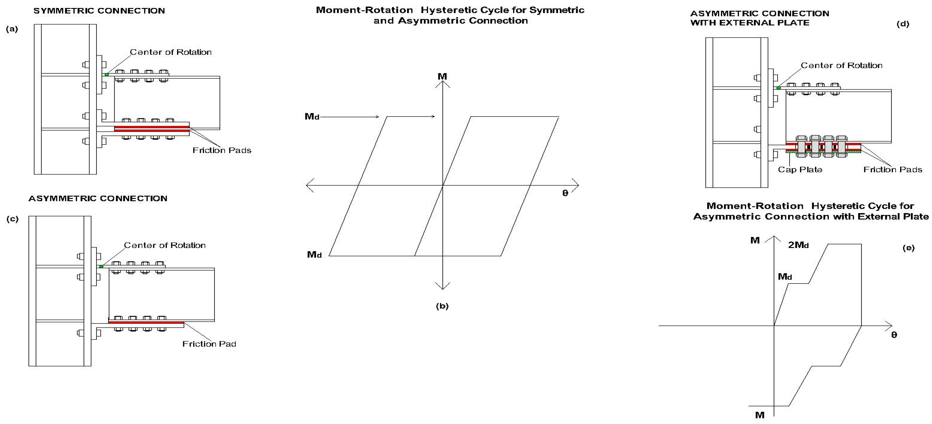
  • Symmetric friction connections (SFC);
  • Asymmetric friction connections (AFC);
  • Asymmetric friction connections with cap plate (AFCCP);
  • Rotational friction devices.
The second part of the paper addresses the common factors affecting the performance of friction-based beam-to-column devices. Thus, firstly the emphasis is on the role of the friction materials (brass, steel, thermal sprayed aluminum, brake materials) [69]. Then, the factors affecting the performance of the devices, mainly the methods of application (torque wrench) and control (disc spring) of the bolt preload, are analyzed. Both are usually investigated by testing uniaxial friction dissipative devices.

3. Symmetric Friction Connections (SFC)

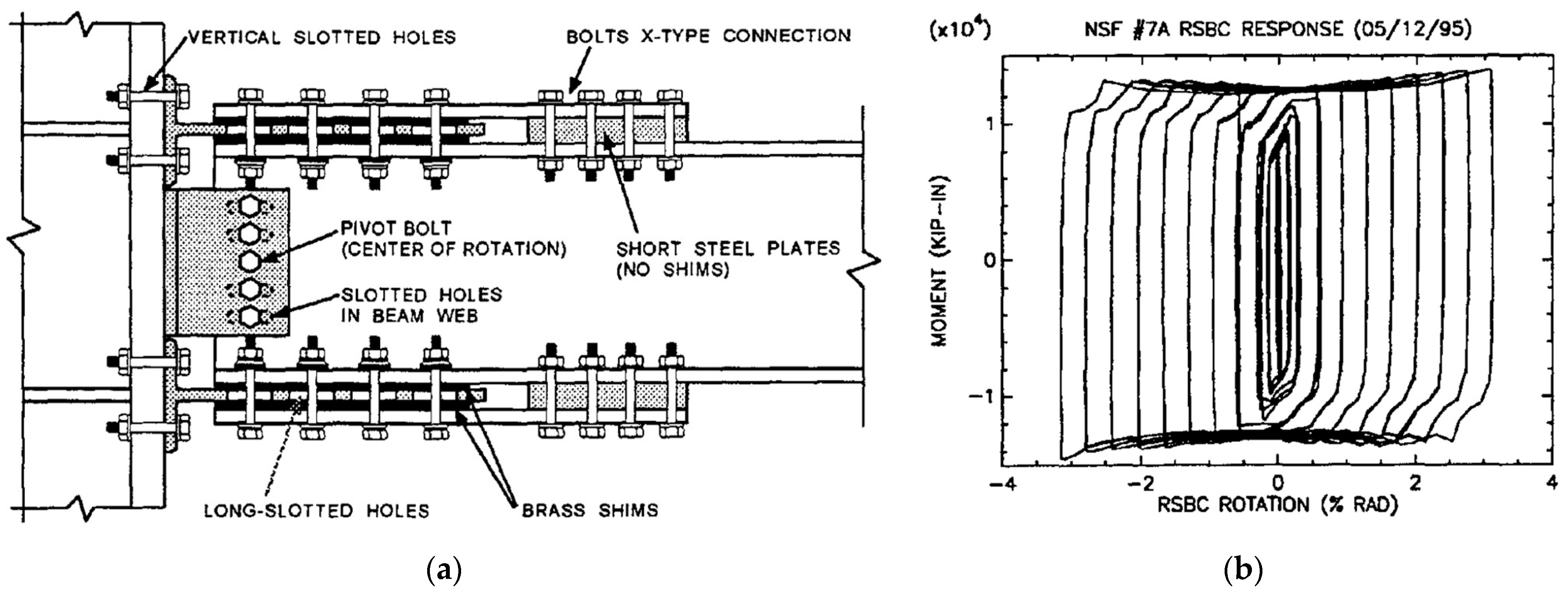
3.1. Rotational Slotted Bolted Connection

One of the pioneer symmetric friction devices applied to BCCs was reported in [80,86] (Figure 3a) by Grigorian and Popov, and Yang and Popov, respectively. The system comprises T-stubs, each of these bolted to the beam flanges and covered by a cap plate. A friction shim is inserted at each interface of the T-stub-cap plate and T-stub-beam flange, in order to form two linear friction devices. On the column flange, a beam web is bolted via vertical steel angles, in which the central bolt acts as the fixed center of rotation, while the other bolts are inserted through slotted holes.
One of the advantages of this solution is that, having a properly defined center of rotation, the kinematic of the connection is readily predictable. However, the position of the center of rotation causes a sensible gap opening during rotation between the column flange and top beam flange, leading to potential damage to the slab. In addition, particular attention should be given to the design of the bolt representing the center of rotation, named the pivot bolt, as well as the plates connected by it.
As a matter of fact, the first of the two specimens tested by [80] showed that no element constituting the connection was damaged at the end of the test, except for the pivot bolt, whose shank was bent by shear. In addition, reversed cyclic action enlarged the hole on the beam web through which the pivot bolt was inserted. For this reason, for the second specimen a larger pivot bolt was adopted, and the beam web was reinforced.
The experimental tests employed brass as the friction shim material. The results showed that, although the brass provided exceptionally stable cyclic behavior, as shown in Figure 3b, its friction coefficient was quite low and required building a connection with many friction surfaces and bolts to obtain proper moment strength. Furthermore, the moment of the connection during the sliding phase showed a slight hardening behavior.
This can be explained by the fact that, once the connection started to rotate, the T-stubs were bent, and the bending moment acting on them contributed to increase the moment of the whole connection. With regard to the shape of the corners of the hysteresis loops, this is due to slippage of the brass pads during load reversal, caused by the clearance hole.
Despite the several flaws affecting the proposed solution, it can be stated that the tested connections behaved outstandingly well. It is worth remembering that this solution was a pioneering one and the application of such friction connections to structural engineering was at the very beginning.

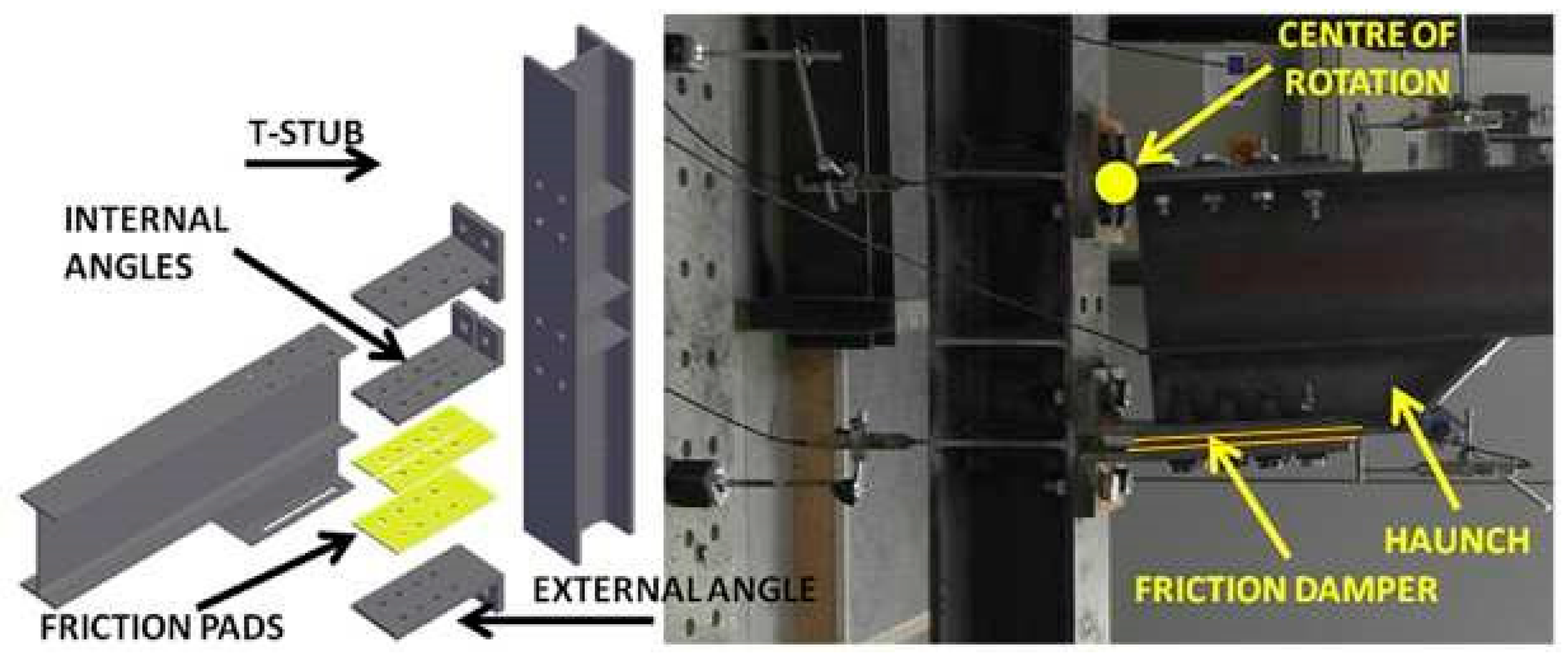
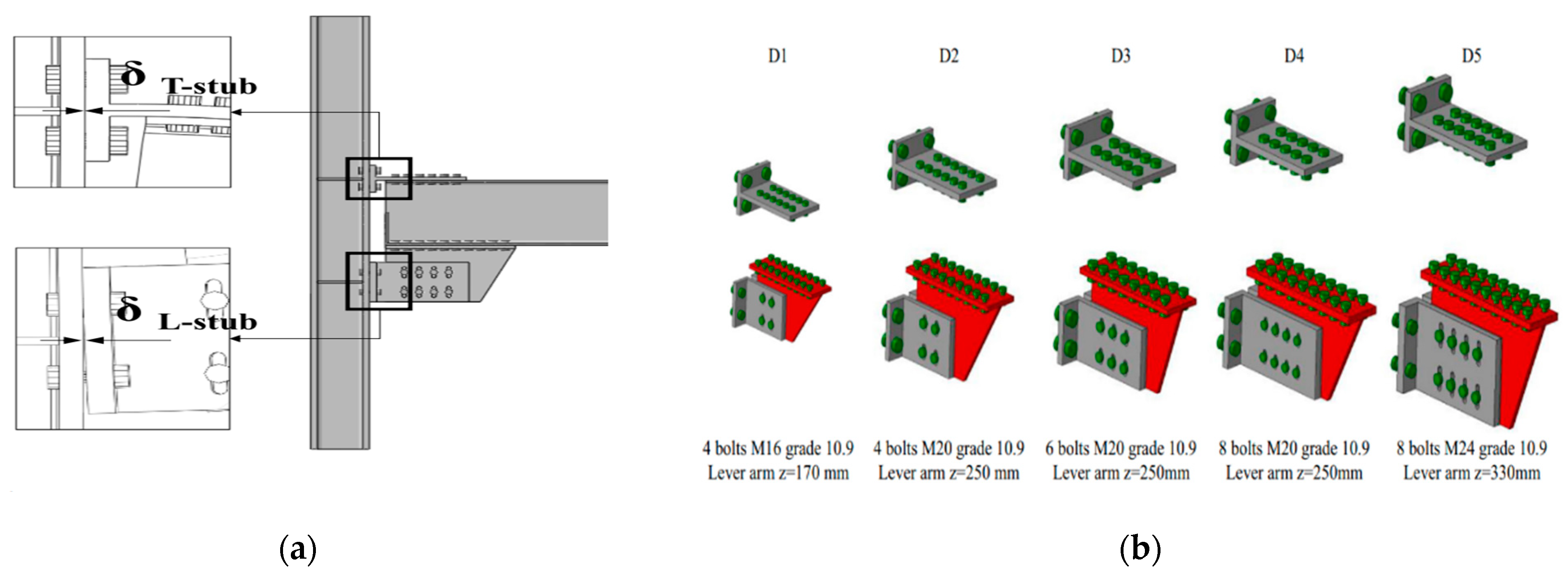
3.2. Removable Friction Dampers for Low-Damage Connections

The research group of the University of Salerno (Italy), in collaboration with the Federico II University of Naples, Italy, has proposed two other solutions. In the first one, the dissipative friction plates slide in the horizontal direction (Figure 4), while in the other the sliding is in the vertical direction [88] (Figure 5). These solutions aim at solving three main flaws of a previously proposed asymmetric solution [84], i.e., the lack of a center of rotation, the asymmetric configuration of the friction connections, and the relatively small moment capacity, which is due to a combination of the small internal lever arm of the connection and the small number of friction surfaces for each side (i.e., equal to 1).
In both of these solutions, an additional steel element (I-shaped for a horizontal dissipative device, while it is T-shaped in the case of a vertical one) is bolted to the bottom beam flange in order to increase the internal lever arm of the joint and reduce the forces acting on the panel zone.
Another advantage provided by the additional steel element is that it makes it possible to double the surfaces on which friction forces are generated, considerably improving the performance of the connections. A T-stub is bolted to the column and upper part of the beam to establish a connection. In both solutions, the center of rotation is expected to form at the base section of the upper T-stub. The solution with the horizontal dissipative device is made by using three steel angles which are bolted to the I-shaped section, having one friction pad for each steel angle (Figure 4).
The solution with the vertical dissipative device needs two steel angles, requiring two groups of slotted holes, one vertically oriented on the steel angles, and the other one horizontally oriented on the T-shaped profile as shown in Figure 5, so the bolts are allowed to move in both directions. By contrast, in the solution with a horizontal dissipative device, the displacement component in the vertical direction is absorbed by deformation of the lower steel angles. It is different from the horizontal system, in which low damage to the lower steel angles is admitted; the vertical one prevents any damage of the friction connection. However, bolts belonging to the friction device are subjected to plastic deformations due to the contact between the horizontal slotted holes of the T-shaped profile and the bolt shanks. The fact is that these bolts have to be dragged up and down by the T-shaped profile, in the vertical direction, to allow connection rotation.
With regard to mechanical behavior, the horizontal system shows an increment of the moment capacity, in both directions, due to the progressive plasticization of the lower steel angles (Figure 6a). As for the vertical system, the contact between bolt shanks and horizontal slotted holes causes an increment of the moment capacity, which depends on the amount of bolt shanks dragged by the T-shaped profile. For this reason, the backbone curve of the moment–rotation behavior shows a sawtooth-like shape (Figure 6b).
The moment capacity increment due to these phenomena has to be properly taken into account when designing the members connected to the friction connection with the aim of avoiding damage formation.
Therefore, it is worth outlining the design procedure of the above connection. The force Fd for which the connection starts to slide can be calculated as follows:
Fd = Md/z
in which Md is the design bending moment and z is the lever arm, being the distance between the center of rotation and the axis of sliding. According to [96], the sliding force Fd can be obtained as
Fd = (Ksnbnsµ/γM3) × Fpc
where Ks = a coefficient that depends on the shape of the slotted hole, nb = the number of bolts, ns = the number of surfaces in contact, µ = the friction coefficient, γM3 = a safety factor, and Fpc = the preloading force of each bolt. Fpc can be assessed as follows:
Fpc = 0.7 ts fub Ares
where fub = the ultimate strength of steel, Ares = the resisting area of the bolt, and ts = a parameter ranging between 0.3 and 0.6, introduced to keep the bolt within the elastic range and thus limit preload losses due to creep phenomena [70,71,72].
Tartaglia et al. [89] conducted a parametric study by using the finite-element simulation and modeling of a steel beam-to-column joint. To this aim, a set of five friction dampers based on the steel profiles used in Eurocode-compliant multi-story moment-resisting frames were used shown in Figure 7. Experimental tests were performed in a previous study [88], and the FEM models were calibrated against those tested before.
The aim of this research was to extend the findings of the experimental results, investigating the behavior of different damping connections. The surface interaction of the plate to plate and bolt to plate were modeled using the tangential and normal behavior. For normal behavior, “Hard Contact” is taken, while tangential behavior is modeled differently for friction pads to steel and steel to steel interfaces.
For friction dampers, the dynamic friction coefficient is taken as 0.59 [97] and for steel-to-steel surfaces it is taken as 0.3. Pre-tensioning of the bolts was performed in order to apply bolt preload according to the recommendation of EN1993:1–8 [96]. The column was allowed to deform along its own axis by pinning it at the bottom end and by allowing all flexural rotations, as well as vertical displacements at the upper end. The beam tip was simply pinned while it was restrained by means of lateral-torsional buckling in accordance with [96]. Both cyclic and monotonic displacement histories were applied at the beam tip in accordance with [98].
The following results can be derived from the simulations.
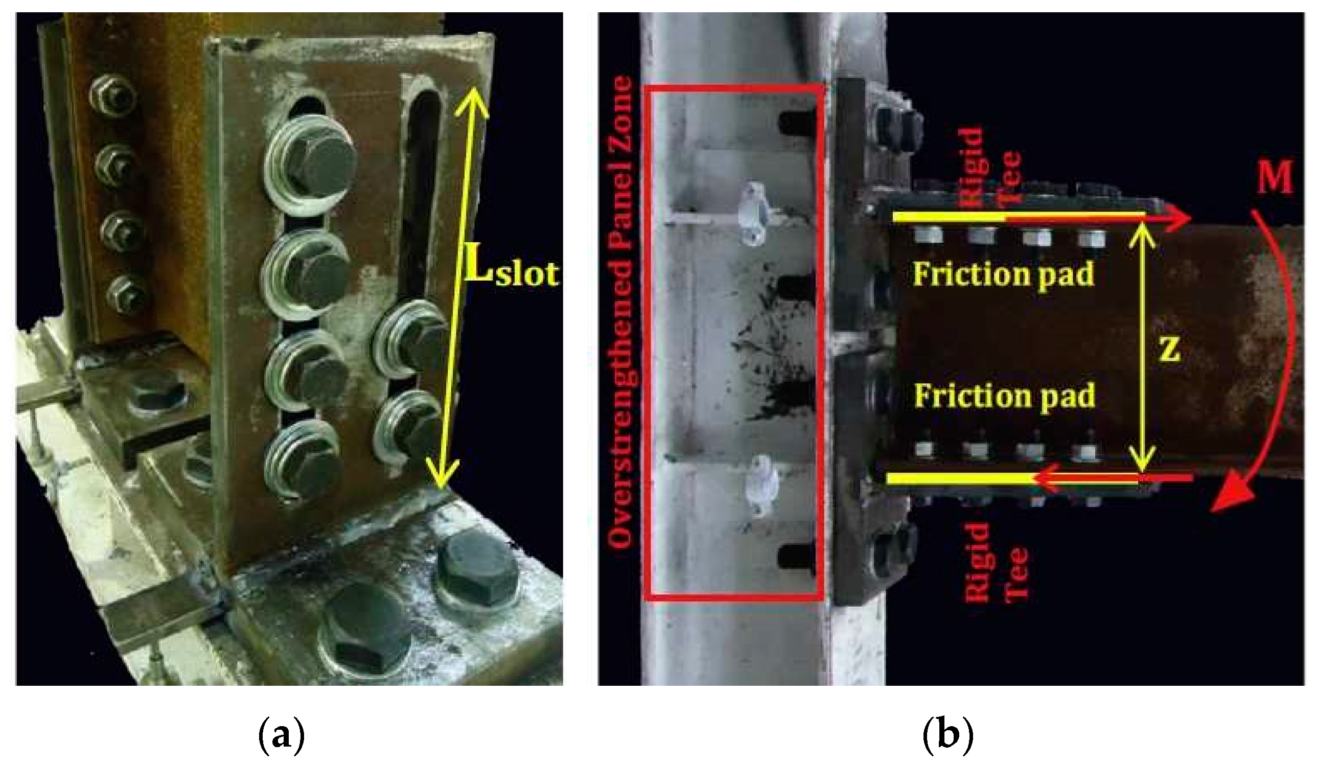
  • The rotational capacity and ductility of the friction connection is dependent on some of the factors like the lever arm of joint, the length of the slotted holes in the rib, and the gap between the beam’s tip and column flange, which restrains contact between the connected members under hogging flexure, while it permits plastic hinge formation at the base of the T-stub web;
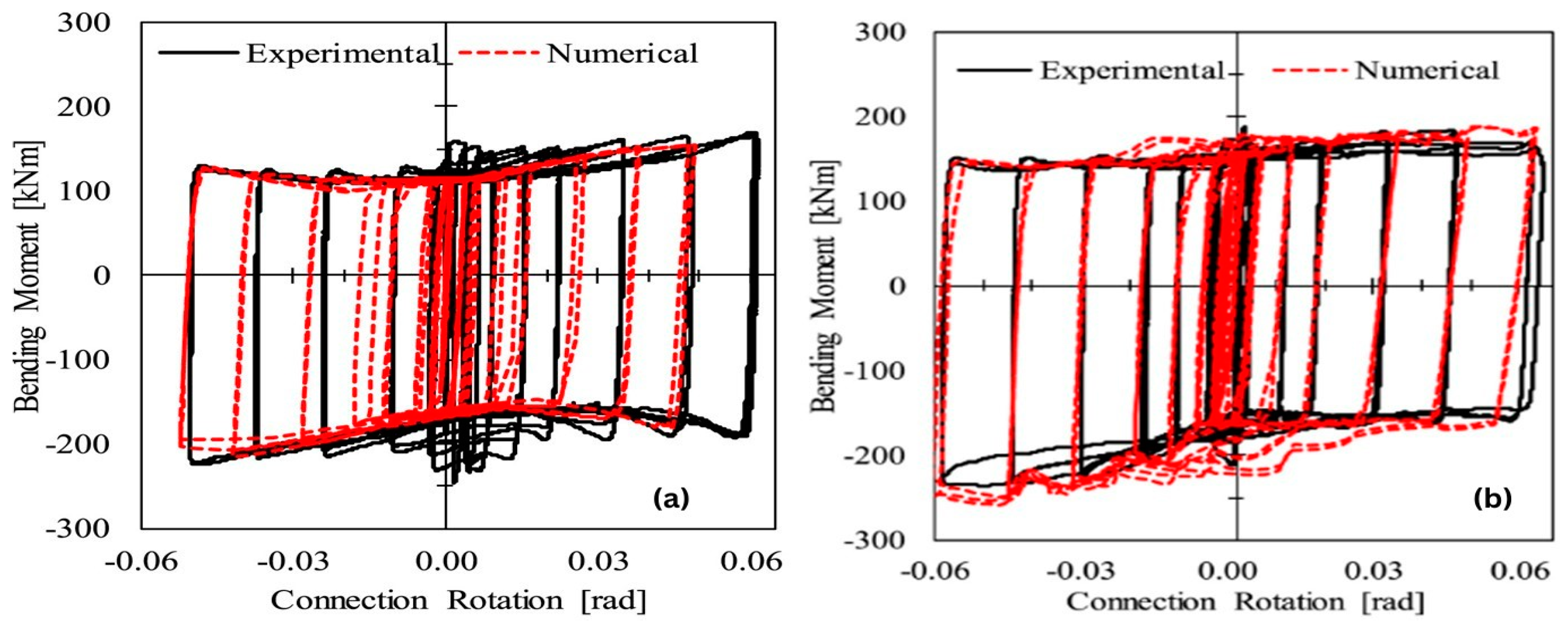
  • It was found that the effectiveness of friction joints is not dependent on the size of the connected members because the hysteretic and monotonic response of all joints was almost the same;
  • The friction dampers and connections give a rotation capacity of about 0.07 rad, which fulfills the minimum rotation capacity criteria given in [99] for dissipative joints;
  • The flexural response of the joints having the proposed dampers is not symmetric, and for the chord rotation of 0.04 rad the hogging resistance is about 25% greater than the sagging resistance. This is mainly due to the higher deformability of L-stubs under the sagging moment, which causes a higher loss of bolt preload as compared to the loss when the L-stubs are in compression.
In order to find the seismic response of low-damage/FREEDAM joints, the authors of [51] tested a large scale two-story building mock-up having two equal frames equipped with low-damage FREEDAM joints having friction dampers as shown in Figure 8.
To simulate seismic event effects, a sequence of five accelerograms was applied by pseudo-dynamic testing. The geometrical details of the tested FREEDAM joint are shown in Figure 9.
The experimental results confirmed that low-yielding friction joints provide enough energy dissipation and rotation supply without any damage. These experimental results were verified by a numerical method.
It was also found that the connection did not suffer any damage but there was minor yielding, as in the results provided by [52] for beam-to-column joints’ sub-assemblages. At the end of tests, the friction pads needed to be repaired because of friction and energy dissipation. There was a slight degradation of the connection’s flexural resistance during the experimental campaign, which proves that friction pads can resist the seismic event, but minor repair may still be needed.

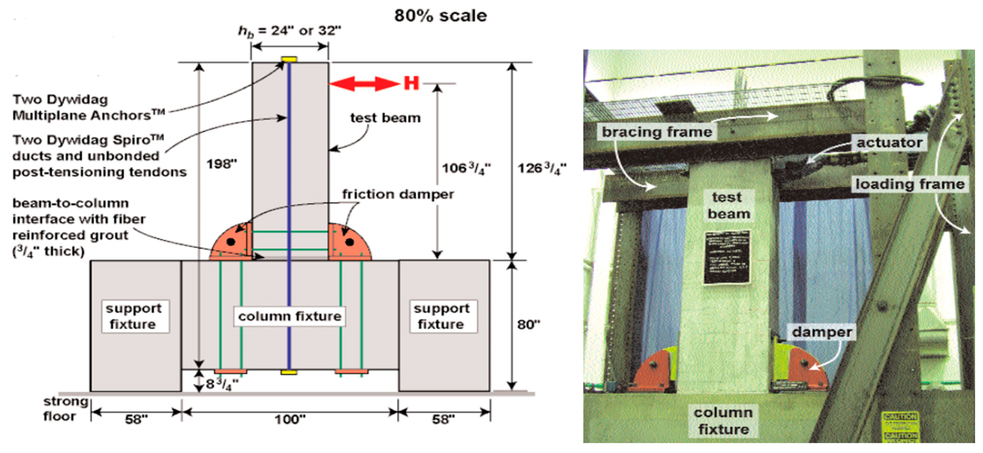
3.3. Self-Centering Friction Connection for PRC MRFs

As underlined in the introduction, in order to obtain devices that guarantee full functionality of the structure after an earthquake, a significant characteristic of the device is recentering capacity. In the literature, various devices are designed according to the methods that characterize the recentering behavior of the device proposed in [44,45,46]. The device shown in Figure 10 was developed for PRC structures.
The connection between the beam and column is established by using two bolts inserted through curved slotted holes. Each dissipative device is constituted by four friction shims (Figure 11).
The beam and column are connected with one or more unbounded post-tensioned tendons, which are placed at the mid-height of the beam cross-section, providing self-centering behavior to the connection. Figure 12 shows the theoretical moment–rotation curve of the self-centering connection, as well as the contribution provided by friction devices and post-tensioned tendons. The latter are characterized by bilinear-elastic behavior, in which the moment value Mbp is tuned by means of the preload force acting on the tendons, while second branch stiffness is ruled by the axial stiffness of the tendons. It should be noted that the theoretical contribution made by post-tensioned tendons does not dissipate energy, with these behaving elastically.
Yet this is not fully confirmed by experimental tests, as can be seen in Figure 13, which shows two moment–rotation curves of a subassembly endowed with post-tensioned tendons and including or not including friction dampers. In both cases, the greater the rotation achieved by the connection, the lower the moment value for which the gap at the beam-to-column interface opens (i.e., without dampers it equals Mbp, Figure 13a; with dampers it equals Mbd, Figure 13b).
This phenomenon was due to concrete cracking and crushing at the beam and column interface. As a matter of fact, this contact is required to transfer the shear force between the beam and column: otherwise, in the presence of friction connections, these would withstand this force and their functioning would be hampered.
Moreover, progressive damage to concrete also leads to hysteretic cycles with a small amplitude in the case of a subassembly without dampers. On a final note, the results provided by post-tensioned tendons are promising in terms of dissipative and self-centering capacities. However, it has to be stressed that this structural typology requires tensioning the tendons in the construction site once the PRC members are put in place, limiting its use to large constructions only.

3.4. Symmetric Vertical Friction Connection for RC Columns and Hybrid Beams

The friction-based BCC proposed in [49,90,91,100] is the only one in the literature designed for connecting RC columns cast in situ connected with HSTCBs. The need to design such a device was highlighted by experimental tests conducted on traditional connections between RC columns and HSTCBs, which highlighted the loss of stiffness caused by the cracking of the joint panel in connections with beams characterized by a high percentage of longitudinal reinforcement [101,102].
The device was designed to connect an HSCTB having dimensions of 300 × 250 mm2 and longitudinal rebars of 4ϕ24 (top) + 2ϕ24 (bottom), taking advantage of the steel plate on the bottom side of the beam, which acts as a mold in the casting phase and as a reinforcing element at the serviceability limit states (SLS) and ultimate limit states (ULS). The transverse reinforcement of the beam was ϕ8/6 cm. A major issue in the design of the devices was the shear strength that had to be provided to the beam, which was calculated as 350 kN using the analytical model of [103], which develops that proposed in [104].
The device specimen is represented in Figure 14b; the T-stub is made of an HEB300 profile, and the connection between the T-stub and HSTCB was made with eight M20 bolts Class 10.9, while the connection between the column and T-stub was made of four M24 bolts Class 10.9. The steel angles were coated with thermal sprayed aluminum and used as friction pads, as shown in Figure 14c. Thermal sprayed aluminum was chosen as the friction material based on its excellent performance as tested by [69]. The connection between the vertical central plate and thermal sprayed aluminum steel angles was established by five M20 bolts Class 10.9 and the thermal sprayed aluminum steel angles were connected with the column with four M24 bolts Class 10.9. In total, 500 kN of axial load was applied on the column to replicate the dead load effect.
Displacement controlled tests were performed on HSTCBs at a distance of l = 1.31 m (from the center of rotation to the point of applied displacement). The displacement history was considered as suggested by ACI 374.2R-13 (2013) [105]. Two cycles of five amplitudes of maximum displacement of ± 2 mm, ± 5 mm, ± 10 mm, ± 20 mm, and ± 40 mm were applied. Several tests were performed, with joint strength equal to 0.35, 0.5, 1, and 1.5 of the ultimate bending strength of the HSTCBs, equal to 105 kN-m. In Figure 14a, the result of the test with the lower strength, namely 36.75 kN-m, is reported, where a torque was applied on the bolts to achieve a preload of 17 kN, and an expected sliding force equal to Fsl = 29 kN. The results showed that the beam–column connection provides stable and wide hysteresis loops without any damage or cracking. There were different values of the sliding force in the case of the sagging moment and hogging moment due to a change in the lever arm. It was also found that the sliding force reduces during the test because of the wearing of the surface and loss of preload force due to the stick and slip phenomenon.

4. Asymmetric Friction Connections (AFC)

4.1. Dissipative Double Split Tee Connection

A solution named the dissipative double split tee connection (DDSTC) [84] was developed at the University of Salerno, Italy. The connection is established by using two T-stubs, which are bolted to the beam flanges having slotted holes in order to permit the bolts to slide (Figure 15). A friction shim is inserted between the beam flange and T-stub in order to provide energy dissipation capacity. The connection is designed in order to allow displacement of the vertical component due to the rotation by means of the deflection of T-stubs. The latter are supposed to undergo plastic deformations at the base section and then to be replaced after the seismic event. This configuration has a variable center of rotation, leading to potential significant damage to the slab.
The experimental tests showed remarkable performance characterized by adequate dissipative capacity and slight hardening behavior due to the bending moment acting on the T-stub flanges, as already seen in the RSBC (Figure 16). The solution simplifies the configuration of the RSBC by removing cap plates and pivot bolt.
The reduction in the number of surfaces on which friction forces are generated, which would lead to a lower moment capacity of the connection, is compensated by using friction shims having a higher friction coefficient. However, by doing so the friction connections become asymmetric and the bolts are subjected to a combined axial force-shear force-bending moment that might lead to plastic deformations of the bolt shanks, potentially causing decreasing clamping forces and a poor cyclic performance of the connection.
Latour et al. [95] conducted an experimental campaign on asymmetric beam-to-column joints and derived an analytical model on the basis of the component method [96]. The main aim of this research was to predict the cyclic behavior of partial-strength BCCs, which helps researchers to correctly analyze the nonlinear response of connections in seismic time-history analyses and to precisely predict the degradation of the sliding properties of friction connections.
The tested beam-to-column joint is like a conventional double split tee connection. However, some modifications are made. In traditional double split tee connections, the bottom T-stub is used to connect the column with the lower flange; but here it is replaced with a friction device in order to have two different geometrical configurations, as shown in Figure 17.
In Configuration 1 (Figure 17a), the symmetrical friction pads are parallel to the beam flange. Here, the device consists of friction shims, 10.9 high-strength preloaded bolts, a couple of L-stubs, and a slotted stainless-steel haunch which allows sliding of the device. To help the transfer of bolt forces and clamp the friction shims and the haunch together, the L-stub is used to connect the assembly with a column flange.
In Configuration 2 (Figure 17b), there is a relative movement of L-stubs and rib plates in friction shims which produce sliding, so all of these elements have slotted holes.
The friction device consists of a stainless-steel plate (lower part of the haunch in Configuration 1 and rib plate in Configuration 2). One of the interesting things is that the damper performs the same way in both cases but a relative decrease or increase in the bolt preloading forces can occur for Configuration 1 due to the flexibility of the L-stubs and rigid beam rotation, while there is no such increase or decrease for Configuration 2 as there is no variation in bolt forces because it is independent of L-stub deformation.
The experimental analysis confirmed that the response of the Configuration 1 joint was asymmetric and caused fluctuations of the bolt preload. This is because of the different deformability of the L-stubs in compression and tension and also due to the non-uniform pressure distribution in the friction interface because of the incompatibility between the bending of L-stub and joint rotation in Configuration 1.
When the specimen is cruciform, the asymmetry disappears at the same time because at the same nodal point one of the connections is under a sagging bending moment while the other is in hogging. Thus, it can be deduced that locally the behavior of the friction joints is asymmetric while the overall response of the moment-resisting frame will be symmetrical for any direction of the seismic forces. This is due to the same number of connections in both bending (hogging and sagging).
The results also show that in Configuration 2, the friction joints are less prone to variation in the bolt forces, which show a less asymmetric response as compared to Configuration 1.

4.2. Two-Level Friction-Yielding System

Among the hybrid solutions mentioned previously, to address the requirements at both the damage limit state (DLS) and ultimate limit state (ULS), Asgari et al. [22] proposed a beam–column node for steel structures made with a “two-stage” damper for BCCs by combining two separate control systems with different strengths and stiffnesses. The system includes one asymmetric friction and one yield damper on the top plate of the beam-to-column joint. In this control system, the frictional damper acts as the first member for dissipating the energy transmitted by an earthquake, and in the case of insufficient capacity, the yielding damper comes into action and dissipates the energy using plastic deformations. The cyclic behavior of these systems was subjected to a nonlinear analysis with ABAQUS 2017 software. Parametric FEM analyses investigate the effect of different values of the length-to-thickness ratio of the friction plate of the upper wing, the ratio between the areas of the plate to be yielded and the section of the beam with elastic behavior, and the force that activates plate sliding. Two specimens were subjected to laboratory tests. The results confirmed the absence of cracking or failure of the welds, or significant variation in the preload bolts, highlighting the effectiveness of the sizing of the proposed rigid connection. Finally, the effectiveness of the device in limiting damage to a steel portal subjected to seismic excitation at the foot, characterized by two different intensity levels, was verified through step integrations of the equation of motion in the nonlinear field by again employing the FEM code.

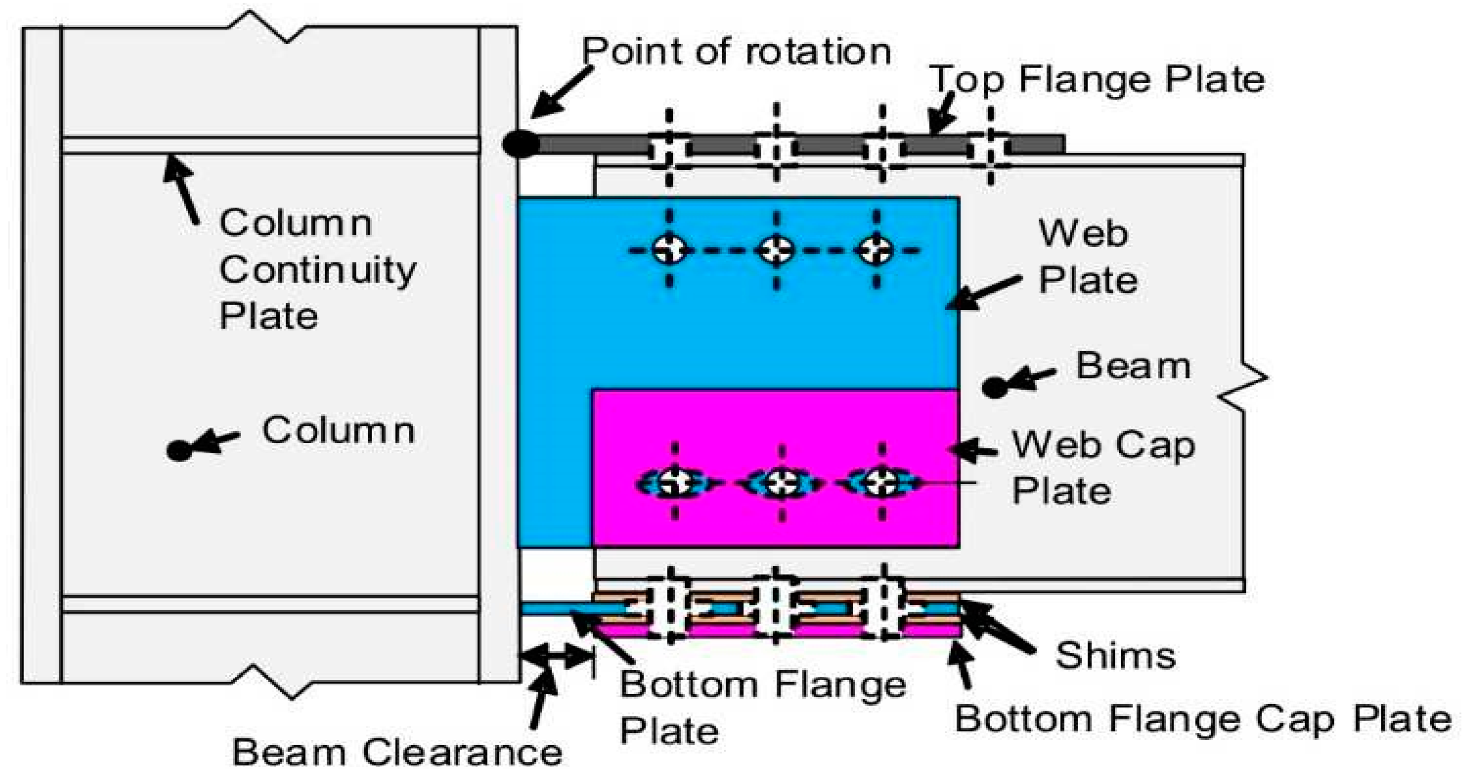
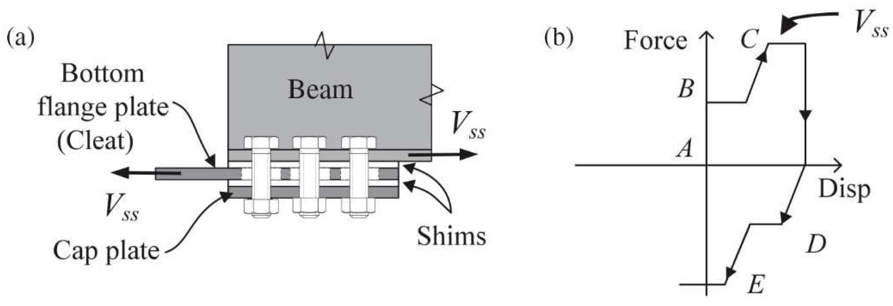
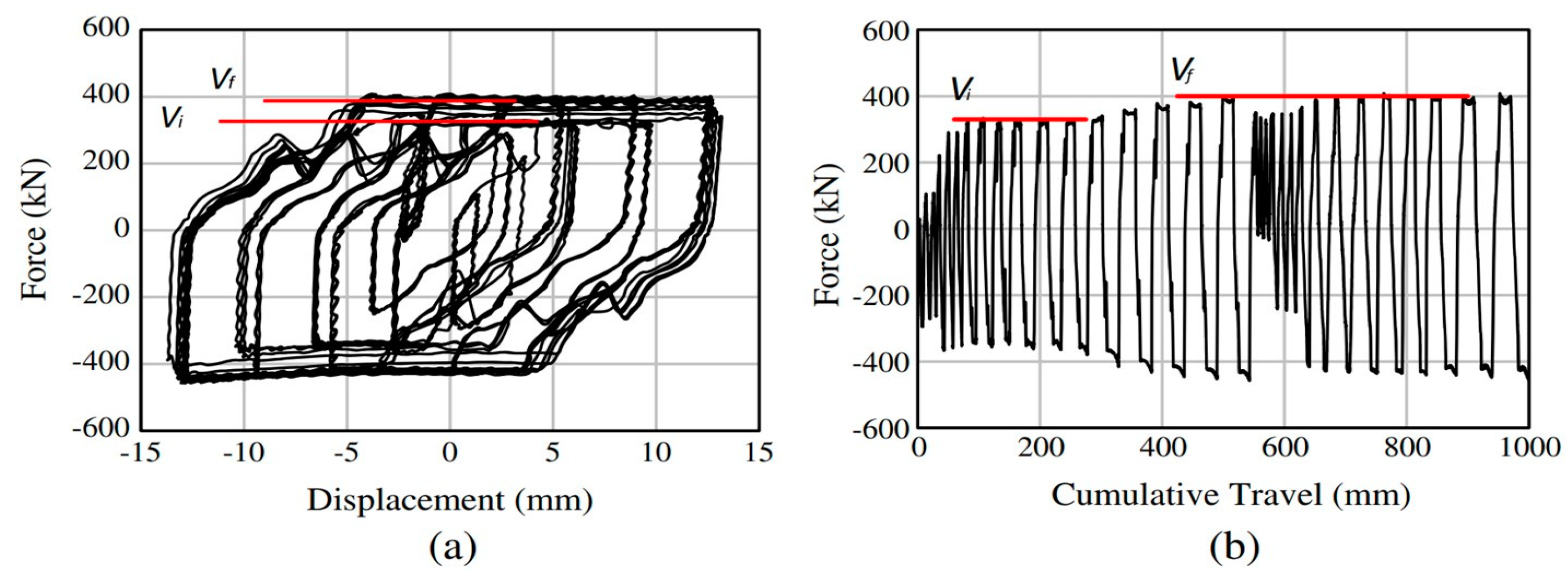
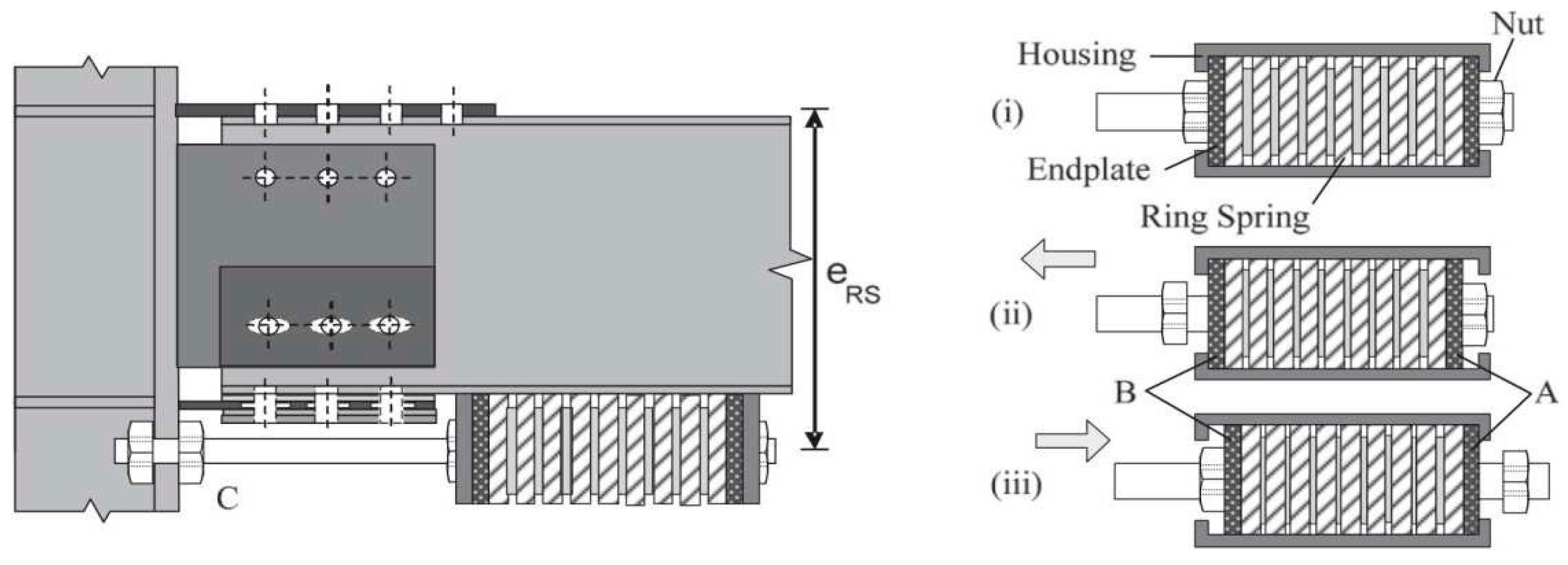
5. Asymmetric Connections with Cap Plate

Sliding Hinge Joint with Asymmetric Friction Connection

Among the most recent connections developed at the University of Auckland and University of Canterbury, an important role is played by the connection named the sliding hinge joint with asymmetric friction connection (SHJAFC) shown in Figure 18 [81,92,93].
The solution solves two main drawbacks affecting the RSBC, namely the center of rotation constituted by a pivot bolt, to which particular attention has to be paid during structural design to avoid any damage to the bolt itself and to the plates connected by it, and the gap opening between the top flange of the beam and the column flange, which could potentially lead to damage to the slab. In SHJAFC, the connection between the beam and column is established by using two horizontal steel plates welded to the flange of the column. The connection between the beam and these plates is established by bolts; the one above is a standard bolted friction connection, while in the one below these are inserted through the slotted holes in order to permit beam rotation.
Another friction shim is placed at the bottom connection by using a cap plate. A vertical plate is welded to the column flange and bolted to the beam web by means of two horizontal rows of bolts. The top one is a standard bolted connection, while the bottom one has horizontal slotted holes which permit beam rotation. Moreover, with the aim to increase the dissipative capacity of the connection, a cap plate is bolted to the outer side of the web plate. Between the cap plate and web plate, and between the web plate and the beam web, two friction shims are inserted.
The rotation of connection starts when the friction forces of the shims inserted between the bottom beam flange and bottom plate, beam web and web plate, are achieved. Increasing the rotation of the system, the total friction force doubles when the friction shims inserted between the bottom and web plates and the cap plates begin to slide (Figure 19).
During the design step of the SHJAFC, special attention must be paid to the serviceability limit state and to wind loads. As a matter of fact, due to the above-mentioned moment–rotation behavior, the connection could start to rotate when subjected to loads different from those caused by the design earthquake. Furthermore, the asymmetric arrangement of the friction device leads to bolts contemporarily subjected to moment, shear, and axial load, which, in early versions of this connection, caused plastic deformations of the bolt shanks. This phenomenon decreased clamping force leading to hysteretic cycles characterized by a progressive reduction in the sliding force. To solve this issue, bolts have to be kept within the elastic range and coupled with disc springs able to absorb the elongation undergone by bolt shanks [94].
When an SHJAFC is endowed with friction pads having a much higher hardness than that of constructional steel, it provides wide and stable hysteretic cycles, with a slight progressive increase in sliding force (Figure 20). This phenomenon is due to the formation of asperities on the surfaces in contact.
From the pioneering configurations developed at the end of the last century, during the last decade the sliding hinge joint (SHJ) has been further developed in order to be self-centering [74,75]. This behavior is obtained by adding to the bottom beam flange a stack of preloaded ring springs inserted in a box-shaped case. A bar is inserted through the ring springs and is bolted to the column flange. The system is designed to deform the ring springs in compression only for both hogging and sagging moment (Figure 21).
Experimental tests carried out on different combinations of moment strength provided by the AFC and the stack of disc springs pointed out that the higher the percentage of moment strength provided by the AFC on the whole moment strength of the connection, the lower the self-centering capacity of the connection itself.
For instance, Figure 22 shows the moment–rotation curve of a self-centering SHJAFC characterized by a percentage of moment capacity provided by preloaded ring springs PRS of 52.4%. It can be seen that, despite PRS being more than half of the whole moment capacity of the connection, significant residual drift was still obtained. Therefore, PRS should be increased by using a better performing and thus more expensive self-centering system. In addition, the connection behaved according to design requirements for rotation of up to 25 mrad.
Above this value, the vertical component of the displacement due to the rotation was no longer negligible and the moment strength increased rapidly. This is due to the fact that the connection was not designed to accommodate large displacements in the vertical direction; thus, some damage could have been experienced by the connection. Moreover, in the case of seismic events leading to rotation well above 25 mrad, the increment in the moment strength of the connection could have led to the formation of a plastic hinge at the beam end or, worse, to damage to the column. For this reason, a real application of this connection should select an appropriate overstrength factor to design the members surrounding the connection to prevent any damage.

6. Rotational Friction Devices

The rotational friction devices shown in Figure 23 were designed in [33,82] to connect the braces and beam of BF, while the work in [106] developed a dissipative connection. In the late 1980s [6], a rotational friction devices was placed between two small link elements placed close to a BCC and orthogonally to the beam and column of a precast reinforced concrete industrial frame, in order to obtain a device.
Regarding the friction BCC of PRCs, most of the dissipative connections use post-tensioned tendons [45,107], which can provide frame recentering capabilities but can be affected by loss of prestressed load for concrete, creep and shrinkage, and steel relaxation. To overcome this problem, one must avoid modification of the stiffness of the elements due to prestressing action and ensure that the resistance level of the connection can be easily adjusted. In [85], the dry-connected rotational friction dissipative BCC for precast concrete (PC) frames based on the principles that characterize the operation of steel structure BCCs was proposed (Figure 24) and tested. The device consists of friction pads (D), a pin (E), pre-tensioned tightening bolts (F), and connectors at the column and beam ends (B1, B2, and C). The friction hinge is connected to the embedded elements (A and G) of the PC beam and the column with bolts. The friction pads are compressed by the tightening bolts.
Recently, in Ma et al. [58] the results of numerical analysis preparatory to the experimental verification of device capabilities were reported, aiming at verifying the performance of a PRC MRF using a prefabricated self-centering concrete beam-to-column joint. The joint was equipped with a controllable plastic hinge consisting of a rotational friction damper able to withstand a bending moment and provide dissipative behavior, a pin shaft to carry the shear force, and disc spring self-centering devices as shown in Figure 25. A numerical analysis performed by a macromodel implemented in Opensees (https://opensees.berkeley.edu/ (accessed on 6 February 2024)) [59] proved the efficiency and energy dissipation capacity of the system. The device is characterized by a flag-shaped moment–rotation relationship, and the optimal value of the ratio α between the bending moment provided by the disc spring self-centering prestressing force 2Fs0 and the bending moment required to activate the damper Mf should be chosen in the range of 1.00–1.30, while the overstrength ratio between the ultimate moment of the beam and the activation moment of the damper should be chosen in the range of 1.3–1.4. It has to be emphasized that the aforementioned values must be confirmed by experimental testing.
In [62], a rotational friction connection for steel MRFs able to control the load-displacement relation at different performance levels is proposed and tested. The connection is characterized by a rotational hinge with a fixed rotation center at the level of the beam axis, obtained by two π-shaped plates with a central pin shaft, and radial slotted holes, and two steel plate linear friction dampers at the top and bottom flanges of the beam. The connection is designed in order to be easily recovered if, in the presence of seismic action, damage to the surface of the steel plate damper or reduction in the bolt preload is detected, as specific tests aimed at simulating a maintenance intervention on the device after a major seismic event have demonstrated.

7. Common Issues Affecting Friction Connections

To obtain optimal behavior for friction devices with low slipping strength, it is very important to have a stable friction coefficient (CoF) between the friction damper interfaces, and precise control over the value and the variation in the bolt preload. Thus, all of the above-mentioned structural solutions are highly influenced by two issues:
  • Characteristics of the friction shim;
  • Values and control of the bolt preload.
As for the former, since the research of [25] where a simple bolted steel plate was adopted, or [26] where the behavior of asbestos brake lining pads was investigated, over the last four decades many research groups have focused their attention on research on materials whose characteristics are optimal for this type of use.
Concerning the application of brake pads, Chan [65] analyzed the performance of automotive brake friction materials taking into account that asbestos-based brake pads are no longer used given the environmental and health implications, while Golondrino et al. [66] performed quasi-static testing of full-scale AFC specimens using different shim materials—mild steel, aluminum, brass, bisalloy of different grades—showing that stable hysteretic behavior and minimum degradation effects can be achieved using shim materials with high Brinell hardness values. Subsequently, they noticed that metal sliding surfaces can develop metal-to-metal corrosion that impairs their performance and friction resistance, and they suggested privileging nonmetallic sliding surfaces, such as bonded non-asbestos D3923 brake pads [67].
Recently, in [63], the behavior of six distinct couplings of materials were analyzed, namely steel–steel, brass–steel, sprayed aluminum–steel, and three interfaces implementing distinct friction rubber-based materials.
Figure 26 shows a typical experimental test for assessment of the friction properties of materials. The specimen is composed of two steel plates, one with a normal clearance holes and the other one with slotted holes, joined by a double cover butt joint. Two friction shims are inserted between the cover plates and two steel plates. The test is carried out by imposing a displacement history on one of the two steel plates.
For instance, in Figure 27, the force–displacement curve of a specimen employing non-superficially treated steel for friction shims is reported.
It can be noticed that by increasing the number of cycles, the required force to activate the slippage of the slotted steel plate increased considerably, tripling the initial value during the last cycles. This phenomenon was due to the increasing roughness of the surfaces in contact, which led to a higher friction coefficient. On the other hand, when superficially treated steel is used for friction shims, the test outcomes can be the opposite, i.e., flattening of the superficial asperities which leads to a lower friction coefficient and, consequently, to decreasing the resistance of the friction connection. It is clear that these phenomena may hamper the cyclic behavior of dissipative friction connections.
For this reason, the optimal friction material has to provide a high friction coefficient in order to maximize the connection performance, whose value remains stable during the cycles. Moreover, materials which might show relaxing phenomena (e.g., polymeric ones) should be avoided. Lastly, material durability must be taken into account, because the environmental conditions in which the connection is used could change the material properties during its life cycle.
It has to be emphasized that Chan and Tang [68] investigated durability issues, stressing that in the literature most of the studies were conducted on the new friction dampers. They performed an experimental campaign in order to investigate the long-term performance of dampers, proving that they are mainly affected by corrosion and contamination by foreign bodies, which ultimately affects the energy dissipation capacity. They found that, with reference to the serviceability limit state, in the worst scenario the beneficial effects of added friction dampers are entirely removed if rust and grease are allowed to build up on friction surfaces.
Regarding the second issue, i.e., bolt preload, this is influenced by the procedure used to apply the preload and short- and long-term loss of preload. As a matter of fact, by using the common procedures to apply the preload (e.g., torque method) it is impractical to apply exactly the required preload. In Figure 28, the effective preload applied to a group of 15 bolts M20 Class 10.9 is shown. The applied preload is measured by using a donut cell load between the bolt head and the steel plate through which the bolt is inserted. As can be seen, the variation is remarkable, having preloads at fractiles 95% and 5% equal to 212 kN and 182 kN, respectively. Therefore, such a variation in the bolt preload affects the cyclic behavior of friction connections. Other than the above-mentioned uncertainties, many studies have investigated the short- and long-term loss of bolt preload, which are mainly due to creep phenomena and flattening of asperities of the surfaces in contact. With the purpose of minimizing these issues, as already mentioned before, several authors, e.g., [70,71], suggest limiting the bolt preload to between 30% and 60% of the maximum value calculated by means of [96].
D’Antimo et al. [72], in order to evaluate the loss of bolt preload under sliding and the possibility of maintaining the bolt preload using Belleville disk springs, carried out three different types of tests, i.e., long-term, mid-term, and short-term ones, and investigated the possibility of reducing the preload loss by different arrangements of conical spring washer; they calibrated an analytical model that attempted to predict the load loss over time. In order to achieve a stable friction coefficient (CoF) between the friction damper interfaces, and precise control over the value and variation in bolt preload, Francavilla et al. [64] worked on innovative friction materials having a stable hysteretic response along with a higher, less varied friction coefficient and predictable/stable slip resistance. The internal surface of the device was made of the stainless steel AISI 304 (chosen for its corrosion resistance) having a superficial hardness of roughly 130 HV, while a coupled material exhibiting higher superficial hardness was chosen. To analyze the variation in the friction coefficient of the tested materials, the experimental layout was as in [71]. To this aim, the uniaxial device shown in Figure 29 was tested.
Specifically, it was connected to the testing machine via a slotted plate made of AISI 304 stainless steel and a steel plate. Pre-stressed external steel plates and friction pads were bolted to these plates using assemblies composed of M20 Class 10.9 high-strength bolts and washers. The friction value along with its degradation over time was determined. The bolt preload values were calibrated at 60% of the proof preloading load. The load protocol was taken according to EN15129 [108], and the specimens were tested under cyclic loading progressively increasing to 25%, 50%, and 100% of the device’s maximum design displacement. Initial tests indicate that, regardless of the surface treatment technique used for the friction surfaces, there is no considerable increase in the performance of the friction devices. On the contrary, when assessing an unproven device, the hysteric behavior is considerably more stable, showing resistance degradation of less than 15%. This enhancement is due to a combination of a friction coefficient with a nearly constant value throughout the entire test, due to a more cohesive interface between the two friction faces during earlier testing, and minimal preload losses in the bolts. This conclusion is verified by an analysis of hysteretic behavior by various test configurations, including the analysis of degradation of actual and effective friction coefficients. As a matter of fact, due to an unsuitable choice of the material coupled at the friction damper interface, at the end of the test a value three times more than the value recorded at the beginning of the test was exhibited.
Pagnotta et al. [69] conducted an experimental study and FEM analysis on uniaxial dissipative devices with different types of friction materials, i.e., steel, brass, and thermal sprayed aluminum. The main aim of the research was to analyze the dissipative capacity, to check the variation in the friction coefficient, and to find the effect of disc spring and bolt preload variation. The tested specimen was configured similar to that proposed by [63] as shown in Figure 30. It is composed of two upper and bottom central steel plates with an S355 profile having a thickness of 15 mm, one plate with standard clearance holes and another with slotted holes. Two friction pads are sandwiched on both sides of the plates with cover plates. Six M12 Class 10.9 bolts are used on the fixed side and four preloaded bolts are on the other sliding side. The design of this uniaxial device was performed according to [109]. The device was tested under cyclic displacements of 7.5 mm, 15 mm, and 30 mm. A total of 40% of the code-consistent bolt preload (24 kN) was applied on each bolt.
The experiment results revealed that thermal sprayed aluminum has a constant friction coefficient after a few initial cycles. The coefficient remains between 0.57 and 0.6, and less bolt preload variation occurs because of the presence of disc springs. By contrast, when brass was used as a friction material large fluctuations of the bolt preload and friction coefficient were observed. The results proved that thermal sprayed aluminum friction pads provide a higher energy dissipation and stable results as compared to brass. FEM analysis was carried out to verify the effectiveness of the uniaxial dissipative device and ability of disc springs. The results also confirmed the effectiveness of uniaxial devices in terms of energy dissipation and proved that disc springs are necessary in order to avoid variation in the bolt preload and the maintenance of contact pressure.

8. Conclusions

On the basis of an analysis of the research devoted to the design and testing of friction devices for BCCs for the seismic protection of MRFs, based mainly on laboratory tests, the following considerations are drawn, which can be used to define solutions for beam-to-column connections, which are the topic of the present research.
  • Symmetric dissipative systems ensure a stable response in terms of bending moment capacity, at the same time reducing the stresses experienced by the bolts; by contrast, they have greater complexity and cost and are widespread mainly in Europe, where the relatively low seismicity makes the use of these solutions attractive for buildings of a certain importance, for which the higher costs for the device are justified;
  • The introduction of a vertical web at the end of the beam, on which the friction forces are exerted, allows the arm of the internal couple to be enlarged, increasing the moment of resistance of the connection; this effective structural solution clashes with the need to reduce the overall dimensions of the device;
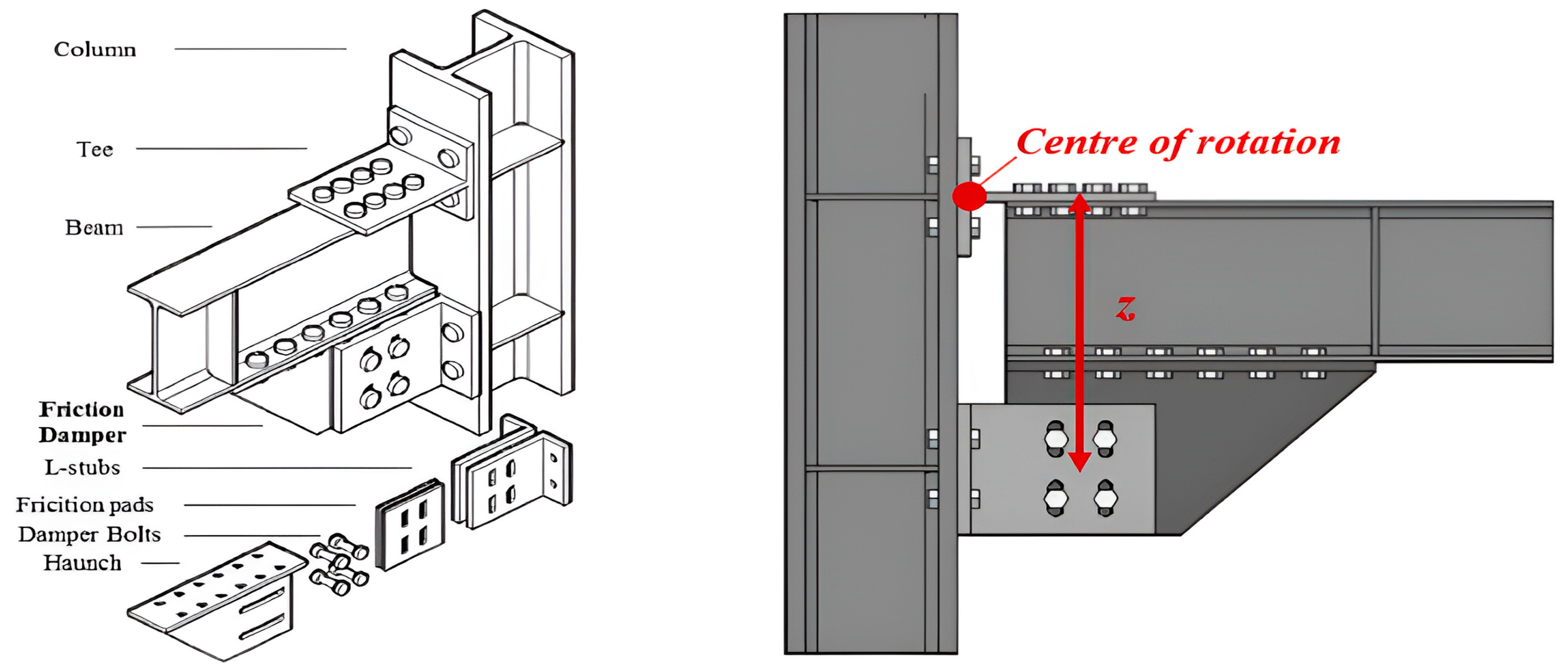
  • The kinematic behavior of the beam-to-column connection is predictable only if it is known prior to the position of the center of rotation;
  • The dissipative device used only at the lower part of the beam ensures identification of a fixed center of rotation, reducing variations in the strength of the connection; its location near the extrados of the beam reduces or avoids damage to the slab;
  • The steel angles connected to the vertical dissipative device remain within the elastic range, simplifying the constructional system with respect to the horizontal dissipative device;
  • T-stubs and/or L-stubs of horizontal dissipative device(s) provide a bending moment contribution during the sliding phase;
  • The vertical dissipative device with two groups of slotted holes, one vertically oriented on the steel angles and the other one horizontally oriented on the friction shims, exhibits an undesired contribution as well, provided by the bolts of friction device which have to be dragged up and down during the sliding phase;
  • Separating the beam end section and the column face prevents damage occurring at this interface.
Thus, among the several solutions presented in this section, symmetric connections with a friction sliding plate in the vertical direction on an added element, with a fixed center of rotation on the top “flange” of the beam, recentering action ensured by pre-compressed ring spring, might seem to be the most balanced ones, being characterized by wide and stable hysteresis loops, bolts subjected to symmetric forces, the ease of realization, and cost-effectiveness. SHJ is an unquestionably excellent solution for beam-to-column connection, and AFC compactness does not introduce any obstacle to architectural layout design. However, the doubling of the sliding force during the functioning of the connection raises some concerns during the design procedure. In addition, the asymmetric configuration of the friction device calls for paying particular attention to the design of the bolts. The fact is that these are subjected to a combined axial force, shear force, and bending moment, and bolt shanks are particularly prone to plastic deformations. Indeed, the latter should be avoided since they could reduce the clamping force of bolts and thus deteriorate the cyclic performance of the connection.
Regarding the self-centering version of the SHJAFC, it seems to provide an effective performance which is linked to a significant increment of the cost of the whole connection. Despite their promising results, the use of friction connections coupled with unbounded post-tensioned tendons in PC structures requires specific procedures during the construction process, which could significantly raise construction costs and make using other structural typologies of recentering system competitive.
The use of hybrid connection devices, with multiple dissipation and recentering systems often connected in series, seems a promising strategy for seismic response control based on multilevel performance criteria, although the higher costs of the device only justify its use for strategic or high-quality buildings.
Regarding the tribological properties of the materials at the interface of the sliding surfaces, research has demonstrated that a steel-on-steel interface showed a high friction coefficient, but quite variable behavior, with an initial hardening phase, followed by a rapid decay of the friction coefficient. A steel-on-brass interface shows stable behavior but is characterized by a low friction coefficient. Steel on thermal sprayed aluminum is characterized by a high value of the friction coefficient and stable behavior if the surface is initially treated to reduce the irregular asperity due to the manual spraying process, minimizing the variability of the friction coefficient with respect to the applied pressure.
The use of nonmetallic sliding surfaces, such as bonded non-asbestos brake pads is a solution capable of ensuring high friction coefficient values but involves reduced durability problems linked to environmental conditions.
Regarding the application and the control of the bolt preload, research has shown that this is influenced by the procedure used to apply the preload, and short and long-term loss of preload. By using the common procedures to apply the preload (e.g., torque method), it is impractical to apply exactly the required preload. In order to ensure minimum dispersion of the applied compressive load, it is recommended to strictly define the torque application procedure, the type of bolts used, and the materials at the interface of the sliding surfaces and at the bolt–washer–plate interface and the type of disc spring used and perform experimental tests for the statistical characterization of the applied preload.
However, the bolt preload is also affected by short- and long-term loss mainly due to the creep phenomenon and flattening of asperities of the surfaces in contact, which are almost unpredictable, but can be efficiently limited both by the use of disc springs and limiting the bolt preload to between 30% and 60% of the maximum value calculated by means of EN1993:1–8 [96].

Author Contributions

Conceptualization, bibliographic researches, methodology, writing—original draft preparation, and review and editing were performed by all authors with the same contribution; funding acquisition, P.C. All authors have read and agreed to the published version of the manuscript.

Funding

The studies presented here were carried out as part of the activities envisaged by the RETURN Extended Partnership and received funding from the European Union Next-Generation EU (National Recovery and Resilience Plan—NRRP, Mission 4, Component 2, Investment 1.3—D.D. 1243 2/8/2022, PE0000005).

Institutional Review Board Statement

Not applicable.

Informed Consent Statement

Not applicable.

Data Availability Statement

Not applicable.

Conflicts of Interest

The authors declare no conflicts of interest.

References

  1. Housner, G.W. Limit Design of Structures to Resist Earthquakes. In Proceedings of the World Conference on Earthquake Engineering, Berkeley, CA, USA, June 1956; pp. 5–13. [Google Scholar]
  2. Kelly, J.M. Aseismic Base Isolation: Review and Bibliography. Soil Dyn. Earthq. Eng. 1986, 5, 202–216. [Google Scholar] [CrossRef]
  3. Cacciola, P.; Tombari, A. Vibrating Barrier: A Novel Device for the Passive Control of Structures under Ground Motion. Proc. R. Soc. A 2015, 471, 20150075. [Google Scholar] [CrossRef] [PubMed]
  4. Colajanni, P.; Papia, M. Hysteretic Behavior Characterization of Friction-Damped Braced Frames. J. Struct. Eng. 1997, 123, 1020–1028. [Google Scholar] [CrossRef]
  5. Akiyama, H. Earthquake-Resistant Limit-State Design for Buildings; University of Tokyo Press: Tokyo, Japan, 1985; ISBN 4-13-068111-7. [Google Scholar]
  6. Martinez-Rueda, J.E.; Elnashai, A.S. A Novel Technique for the Retrofitting of Reinforced Concrete Structures. Eng. Struct. 1995, 17, 359–371. [Google Scholar] [CrossRef]
  7. Skinner, R.I.; Kelly, J.M.; Heine, A.J. Hysteretic Dampers for Earthquake-resistant Structures. Earthq. Eng. Struct. Dyn. 1974, 3, 287–296. [Google Scholar] [CrossRef]
  8. Cao, X.-Y.; Shen, D.; Feng, D.-C.; Wang, C.-L.; Qu, Z.; Wu, G. Seismic Retrofitting of Existing Frame Buildings through Externally Attached Sub-Structures: State of the Art Review and Future Perspectives. J. Build. Eng. 2022, 57, 104904. [Google Scholar] [CrossRef]
  9. Pall, A.S. Friction Devices for Aseismic Design of Buildings. In Proceedings of the Fourth Canadian Conference on Earthquake Engineering: Proceedings; University of British Columbia: Vancouver, BC, Canada, 1983; pp. 475–484. [Google Scholar]
  10. Pasquin, C.; Leboeuf, N.; Pall, R.T.; Pall, A. Friction Dampers for Seismic Rehabilitation of Eaton’s Building, Montreal. In Proceedings of the 13th World Conference on Earthquake Engineering, Vancouver, BC, Canada, 1–6 August 2004; pp. 1–2. [Google Scholar]
  11. Gledhill, S.; Sidwell, G.; Khoo, H.H.; Clifton, G.C. Steel Moment Frames with Sliding Hinge Joints—Lessons Learnt during Implementation. In Proceedings of the Steel Innovations Conference, Christchurch, New Zealand, 21–22 February 2013; pp. 21–22. [Google Scholar]
  12. Gledhill, S.M.; Sidwell, G.K.; Bell, D.K. The Damage Avoidance Design of Tall Steel Frame Buildings-Fairlie Terrace Student Accommodation Project, Victoria University of Wellington. In Proceedings of the New Zealand Society of Earthquake Engineering Annual Conference, Taupo, New Zealand, 11–13 April 2008; pp. 11–13. [Google Scholar]
  13. Ansal, A. (Ed.) Perspectives on European Earthquake Engineering and Seismology: Volume 2; Geotechnical, Geological and Earthquake Engineering; Springer International Publishing: Cham, Switzerland, 2015; Volume 39, ISBN 978-3-319-16963-7. [Google Scholar]
  14. Oxford Terrace Christchurch, New Zealand. Available online: https://www.Tectonus.Com/Projects/Oxford-Terrace (accessed on 6 February 2024).
  15. Benfratello, S.; Palizzolo, L.; Vazzano, S. A New Design Problem in the Formulation of a Special Moment Resisting Connection Device for Preventing Local Buckling. Appl. Sci. 2021, 12, 202. [Google Scholar] [CrossRef]
  16. Benfratello, S.; Caddemi, S.; Palizzolo, L.; Pantò, B.; Rapicavoli, D.; Vazzano, S. Targeted Steel Frames by Means of Innovative Moment Resisting Connections. J. Constr. Steel Res. 2021, 183, 106695. [Google Scholar] [CrossRef]
  17. Benfratello, S.; Cucchiara, C.; Palizzolo, L.; Tabbuso, P. Fixed Strength and Stiffness Hinges for Steel Frames. In Proceedings of the 23rd Conference of the Italian Association of Theoretical and Applied Mechanics (AIMETA 2017), Salerno, Italy, 4–7 September 2017; Volume 1, pp. 1287–1296. [Google Scholar]
  18. Jaisee, S.; Yue, F.; Chen, L.; Yin, W.; Gong, H.; Wang, C. Shaking Table Investigations on the Seismic Performance of a Steel Frame with Optimized Passive Energy Dissipation Devices. IOP Conf. Ser. Earth Environ. Sci. 2019, 330, 022081. [Google Scholar] [CrossRef]
  19. Jaisee, S.; Yue, F.; Ooi, Y.H. A State-of-the-Art Review on Passive Friction Dampers and Their Applications. Eng. Struct. 2021, 235, 112022. [Google Scholar] [CrossRef]
  20. Roh, J.-E.; Hur, M.-W.; Choi, H.-H.; Lee, S.-H. Development of a Multiaction Hybrid Damper for Passive Energy Dissipation. Shock Vib. 2018, 2018, 5630746. [Google Scholar] [CrossRef]
  21. Kim, J.; Shin, H. Seismic Loss Assessment of a Structure Retrofitted with Slit-Friction Hybrid Dampers. Eng. Struct. 2017, 130, 336–350. [Google Scholar] [CrossRef]
  22. Asgari, H.; Zahrai, S.M.; Vajdian, M.; Mirhosseini, S.M. Cyclic Testing of Two-Level Control System Using Friction-Yielding Top Plates in Beam-to-Column Rigid Connections. Structures 2024, 59, 105696. [Google Scholar] [CrossRef]
  23. Janke, L.; Czaderski, C.; Motavalli, M.; Ruth, J. Applications of Shape Memory Alloys in Civil Engineering Structures—Overview, Limits and New Ideas. Mater. Struct. 2005, 38, 578–592. [Google Scholar]
  24. Higazey, M.M.; Alshannag, M.J.; Alqarni, A.S. Numerical Investigation on the Performance of Exterior Beam–Column Joints Reinforced with Shape Memory Alloys. Buildings 2023, 13, 1801. [Google Scholar] [CrossRef]
  25. Pall, A.S.; Marsh, C.; Fazio, P. Friction Joints for Seismic Control of Large Panel Structures. J. Prestress. Concr. Inst. 1980, 25, 38–61. [Google Scholar] [CrossRef]
  26. Pall, A.S.; Marsh, C. Response of Friction Damped Braced Frames. J. Struct. Div. 1982, 108, 1313–1323. [Google Scholar] [CrossRef]
  27. Chen, W.-F.; Lui, E.M. Handbook of Structural Engineering; CRC Press: Boca Raton, FL, USA, 2005; ISBN 1-4200-3993-8. [Google Scholar]
  28. Soong, T.T.; Dargush, G.F. Passive Energy Dissipation Systems in Structural Engineering; Wiley: Chichester, UK; New York, NY, USA, 1997; ISBN 978-0-471-96821-4. [Google Scholar]
  29. Symans, M.D.; Charney, F.A.; Whittaker, A.S.; Constantinou, M.C.; Kircher, C.A.; Johnson, M.W.; McNamara, R.J. Energy Dissipation Systems for Seismic Applications: Current Practice and Recent Developments. J. Struct. Eng. 2008, 134, 3–21. [Google Scholar] [CrossRef]
  30. Perkowski, W. Dry friction damper for supercritical drive shaft. J. KONES Powertrain Transp. 2016, 23, 389–396. [Google Scholar] [CrossRef]
  31. Pesaresi, L.; Stender, M.; Ruffini, V.; Schwingshackl, C.W. DIC Measurement of the Kinematics of a Friction Damper for Turbine Applications. In Dynamics of Coupled Structures, Volume 4: Proceedings of the 35th IMAC, A Conference and Exposition on Structural Dynamics 2017; Springer: Berlin/Heidelberg, Germany, 2017; pp. 93–101. [Google Scholar]
  32. Csaba, G. Modelling of a Microslip Friction Damper Subjected to Translation and Rotation. In Turbo Expo: Power for Land, Sea, and Air; American Society of Mechanical Engineers: New York, NY, USA, 1999; Volume 78613, p. V004T03A012. [Google Scholar]
  33. Sanati, M.; Khadem, S.E.; Mirzabagheri, S.; Sanati, H.; Khosravieh, M.Y. Performance Evaluation of a Novel Rotational Damper for Structural Reinforcement Steel Frames Subjected to Lateral Excitations. Earthq. Eng. Eng. Vib. 2014, 13, 75–84. [Google Scholar] [CrossRef]
  34. Lee, C.-H.; Kim, J.; Kim, D.-H.; Ryu, J.; Ju, Y.K. Numerical and Experimental Analysis of Combined Behavior of Shear-Type Friction Damper and Non-Uniform Strip Damper for Multi-Level Seismic Protection. Eng. Struct. 2016, 114, 75–92. [Google Scholar] [CrossRef]
  35. Titirla, M.D.; Papadopoulos, P.K.; Doudoumis, I.N.; Katakalos, K.V. Cyclic Response of an Antisesmic Steel Device for Building–an Experimental and Numerical Study. In Proceedings of the 16th World Conference on Earthquake Engineering, Chilean Association on Seismology and Earthquake Engineering (ACHISINA), Santiago, Chile, 9–13 January 2017; pp. 1–11. [Google Scholar]
  36. Titirla, M.D.; Papadopoulos, P.K.; Doudoumis, I.N. Finite Element Modelling of an Innovative Passive Energy Dissipation Device for Seismic Hazard Mitigation. Eng. Struct. 2018, 168, 218–228. [Google Scholar] [CrossRef]
  37. Bagheri, S.; Barghian, M.; Saieri, F.; Farzinfar, A. U-Shaped Metallic-Yielding Damper in Building Structures: Seismic Behavior and Comparison with a Friction Damper. Structures 2015, 3, 163–171. [Google Scholar] [CrossRef]
  38. Gagnon, L.; Morandini, M.; Ghiringhelli, G.L. A Review of Friction Damping Modeling and Testing. Arch. Appl. Mech. 2020, 90, 107–126. [Google Scholar] [CrossRef]
  39. Titirla, M.D. A State-of-the-Art Review of Passive Energy Dissipation Systems in Steel Braces. Buildings 2023, 13, 851. [Google Scholar] [CrossRef]
  40. Lai, Z.; Fischer, E.C.; Varma, A.H. Database and Review of Beam-to-Column Connections for Seismic Design of Composite Special Moment Frames. J. Struct. Eng. 2019, 145, 04019023. [Google Scholar] [CrossRef]
  41. Ugalde, D.; Almazán, J.L.; Santa María, H.; Guindos, P. Seismic Protection Technologies for Timber Structures: A Review. Eur. J. Wood Prod. 2019, 77, 173–194. [Google Scholar] [CrossRef]
  42. Rebouças, A.S.; Mehdipour, Z.; Branco, J.M.; Lourenço, P.B. Ductile Moment-Resisting Timber Connections: A Review. Buildings 2022, 12, 240. [Google Scholar] [CrossRef]
  43. Wakashima, Y.; Ishikawa, K.; Shimizu, H.; Kitamori, A.; Matsubara, D.; Tesfamariam, S. Dynamic and Long-Term Performance of Wood Friction Connectors for Timber Shear Walls. Eng. Struct. 2021, 241, 112351. [Google Scholar] [CrossRef]
  44. Morgen, B.G.; Kurama, Y.C. A Friction Damper for Post-Tensioned Precast Concrete Moment Frames. PCI J. 2004, 49, 112–133. [Google Scholar] [CrossRef]
  45. Morgen, B.G.; Kurama, Y.C. Seismic Design of Friction-Damped Precast Concrete Frame Structures. J. Struct. Eng. 2007, 133, 1501–1511. [Google Scholar] [CrossRef]
  46. Morgen, B.G.; Kurama, Y.C. Seismic Response Evaluation of Posttensioned Precast Concrete Frames with Friction Dampers. J. Struct. Eng. 2008, 134, 132–145. [Google Scholar] [CrossRef]
  47. Huang, L.; Zhou, Z.; Clayton, P.M.; Zeng, B.; Qiu, J. Experimental Investigation of Friction-Damped Self-Centering Prestressed Concrete Beam-Column Connections with Hidden Corbels. J. Struct. Eng. 2020, 146, 04019228. [Google Scholar] [CrossRef]
  48. Huang, L.; Clayton, P.M.; Zhou, Z. Seismic Design and Performance of Self-Centering Precast Concrete Frames with Variable Friction Dampers. Eng. Struct. 2021, 245, 112863. [Google Scholar] [CrossRef]
  49. Pagnotta, S.; Monaco, A.; Colajanni, P.; La Mendola, L. Experimental Characterization of Friction Properties of Materials for Innovative Beam-to-Column Dissipative Connection for Low-Damage RC Structures. Procedia Struct. Integr. 2023, 44, 1909–1916. [Google Scholar] [CrossRef]
  50. Colajanni, P.; La Mendola, L.; Monaco, A.; Pagnotta, S. Design of RC Joints Equipped with Hybrid Trussed Beams and Friction Dampers. Eng. Struct. 2021, 227, 111442. [Google Scholar] [CrossRef]
  51. Di Benedetto, S.; Francavilla, A.B.; Latour, M.; Piluso, V.; Rizzano, G. Experimental Response of a Large-Scale Two-Storey Steel Building Equipped with Low-Yielding Friction Joints. Soil Dyn. Earthq. Eng. 2022, 152, 107022. [Google Scholar] [CrossRef]
  52. Francavilla, A.B.; Latour, M.; Piluso, V.; Rizzano, G. Design Criteria for Beam-to-Column Connections Equipped with Friction Devices. J. Constr. Steel Res. 2020, 172, 106240. [Google Scholar] [CrossRef]
  53. Guo, T.; Wang, L.; Xu, Z.; Hao, Y. Experimental and Numerical Investigation of Jointed Self-Centering Concrete Walls with Friction Connectors. Eng. Struct. 2018, 161, 192–206. [Google Scholar] [CrossRef]
  54. Cho, C.; Kwon, M. Development and Modeling of a Frictional Wall Damper and Its Applications in Reinforced Concrete Frame Structures. Earthq. Engng. Struct. Dyn. 2004, 33, 821–838. [Google Scholar] [CrossRef]
  55. Ramirez, J.M.; Tirca, L. Numerical Simulation and Design of Friction-Damped Damped Steel Frame Structures. In Proceedings of the 15th World Conference on Earthquake Engineering 2012 (15WCEE), Lisbon, Portugal, 24–28 September 2012; p. 15052, ISBN 978-1-63439-651-6. [Google Scholar]
  56. Colajanni, P.; La Mendola, L.; Monaco, A.; Pagnotta, S. Seismic Performance of Earthquake-Resilient RC Frames Made with HSTC Beams and Friction Damper Devices. J. Earthq. Eng. 2022, 26, 7787–7813. [Google Scholar] [CrossRef]
  57. Sivaselvan, M.V.; Reinhorn, A.M. Hysteretic Models for Deteriorating Inelastic Structures. J. Eng. Mech. 2000, 126, 633–640. [Google Scholar] [CrossRef]
  58. Ma, L.; Shi, Q.; Wang, B.; Tao, Y.; Wang, P. Research on Design and Numerical Simulation of Self-Centering Prefabricated RC Beam-Column Joint with Pre-Pressed Disc Spring Devices. Soil Dyn. Earthq. Eng. 2023, 166, 107762. [Google Scholar] [CrossRef]
  59. McKenna, F. OpenSees: A Framework for Earthquake Engineering Simulation. Comput. Sci. Eng. 2011, 13, 58–66. [Google Scholar] [CrossRef]
  60. Huang, L.; Qian, Z.; Meng, Y.; Jiang, K.; Zhang, J.; Sang, C. Parametric Investigation of Self-Centering Prestressed Concrete Frame Structures with Variable Friction Dampers. Buildings 2023, 13, 3029. [Google Scholar] [CrossRef]
  61. Colajanni, P.; La Mendola, L.; Monaco, A.; Pagnotta, S. Dissipative Connections of Rc Frames with Prefabricated Steel-Trussed-Concrete Beams. Ing. Sismica 2020, 37, 51–63. [Google Scholar]
  62. Liu, R.; Wu, J.; Yan, G.; Lai, Q.; Wang, H. Seismic Performance of Earthquake-Resilient Beam-to-Column Connection Considering Friction-Slip Mechanism. J. Build. Eng. 2023, 75, 107055. [Google Scholar] [CrossRef]
  63. Latour, M.; Piluso, V.; Rizzano, G. Experimental Analysis on Friction Materials for Supplemental Damping Devices. Constr. Build. Mater. 2014, 65, 159–176. [Google Scholar] [CrossRef]
  64. Francavilla, A.B.; Latour, M.; Rizzano, G. Prototype Test of Resilient Friction Materials for Seismic Dampers. Materials 2023, 16, 7336. [Google Scholar] [CrossRef]
  65. Chan, D.; Stachowiak, G.W. Review of Automotive Brake Friction Materials. Proc. Inst. Mech. Eng. Part D J. Automob. Eng. 2004, 218, 953–966. [Google Scholar] [CrossRef]
  66. Golondrino, J.C.; MacRae, G.; Clifton, C. Behaviour of Asymmetrical Friction Connections Using Different Shim Materials. In Proceedings of the New Zealand Society for Earthquake Engineering Conference, Christchurch, New Zealand, 13–15 April 2012. [Google Scholar]
  67. Chanchi Golondrino, J.C.; MacRae, G.A.; Chase, J.G.; Rodgers, G.W.; Clifton, G.C. Hysteretic Behaviour of Asymmetrical Friction Connections Using Brake Pads of D3923. Structures 2018, 16, 164–175. [Google Scholar] [CrossRef]
  68. Chan, R.W.K.; Tang, W. Serviceability Conditions of Friction Dampers for Seismic Risk Mitigations. Structures 2022, 35, 500–510. [Google Scholar] [CrossRef]
  69. Pagnotta, S.; Ahmed, M.; Colajanni, P. Experimental and finite element analysis of the cyclic behaviour of linear dissipative devices. In COMPDYN Proceedings; Eccomas Proceedia 2023; National Technical University of Athens: Athens, Greece, 2023; pp. 3077–3090. ISSN 2623-3347. [Google Scholar]
  70. Ferrante Cavallaro, G.; Francavilla, A.; Latour, M.; Piluso, V.; Rizzano, G. Experimental Behaviour of Innovative Thermal Spray Coating Materials for FREEDAM Joints. Compos. Part B Eng. 2017, 115, 289–299. [Google Scholar] [CrossRef]
  71. Ferrante Cavallaro, G.; Latour, M.; Francavilla, A.B.; Piluso, V.; Rizzano, G. Standardised Friction Damper Bolt Assemblies Time-Related Relaxation and Installed Tension Variability. J. Constr. Steel Res. 2018, 141, 145–155. [Google Scholar] [CrossRef]
  72. D’Antimo, M.; Latour, M.; Cavallaro, G.F.; Jaspart, J.-P.; Ramhormozian, S.; Demonceau, J.-F. Short- and Long- Term Loss of Preloading in Slotted Bolted Connections. J. Constr. Steel Res. 2020, 167, 105956. [Google Scholar] [CrossRef]
  73. Belleri, A.; Marini, A.; Riva, P.; Nascimbene, R. Dissipating and Re-Centring Devices for Portal-Frame Precast Structures. Eng. Struct. 2017, 150, 736–745. [Google Scholar] [CrossRef]
  74. Khoo, H.-H.; Clifton, C.; Butterworth, J.; MacRae, G.; Gledhill, S.; Sidwell, G. Development of the Self-Centering Sliding Hinge Joint with Friction Ring Springs. J. Constr. Steel Res. 2012, 78, 201–211. [Google Scholar] [CrossRef]
  75. Khoo, H.-H.; Clifton, C.; Butterworth, J.; MacRae, G. Experimental Study of Full-Scale Self-Centering Sliding Hinge Joint Connections with Friction Ring Springs. J. Earthq. Eng. 2013, 17, 972–997. [Google Scholar] [CrossRef]
  76. Iyama, J.; Seo, C.-Y.; Ricles, J.M.; Sause, R. Self-Centering MRFs with Bottom Flange Friction Devices under Earthquake Loading. J. Constr. Steel Res. 2009, 65, 314–325. [Google Scholar] [CrossRef]
  77. Tsai, K.-C.; Chou, C.-C.; Lin, C.-L.; Chen, P.-C.; Jhang, S.-J. Seismic Self-centering Steel Beam-to-column Moment Connections Using Bolted Friction Devices. Earthq. Eng. Struct. Dyn. 2008, 37, 627–645. [Google Scholar] [CrossRef]
  78. Campione, G.; Cannella, F. Overstrength Requirements to Avoid Brittle Shear Failure in RC Slender Beams with Stirrups. Eng. Fail. Anal. 2020, 118, 104815. [Google Scholar] [CrossRef]
  79. FitzGerald, T.F.; Anagnos, T.; Goodson, M.; Zsutty, T. Slotted Bolted Connections in Aseismic Design for Concentrically Braced Connections. Earthq. Spectra 1989, 5, 383–391. [Google Scholar] [CrossRef]
  80. Yang, T.-S. Experimental and Analytical Studies of Steel Connections and Energy Dissipators; University of California: Berkeley, CA, USA; U.S. Department of Commerce, National Technical Information Service: Alexandria, VA, USA, 1995; PB 97-186803.
  81. Khoo, H.; Clifton, C.; MacRae, G.; Zhou, H.; Ramhormozian, S. Proposed Design Models for the Asymmetric Friction Connection. Earthq. Engng. Struct. Dyn. 2015, 44, 1309–1324. [Google Scholar] [CrossRef]
  82. Mualla, I.H.; Belev, B. Performance of Steel Frames with a New Friction Damper Device under Earthquake Excitation. Eng. Struct. 2002, 24, 365–371. [Google Scholar] [CrossRef]
  83. Mirtaheri, M.; Zandi, A.P.; Samadi, S.S.; Samani, H.R. Numerical and Experimental Study of Hysteretic Behavior of Cylindrical Friction Dampers. Eng. Struct. 2011, 33, 3647–3656. [Google Scholar] [CrossRef]
  84. Latour, M.; Piluso, V.; Rizzano, G. Free from Damage Beam-to-Column Joints: Testing and Design of DST Connections with Friction Pads. Eng. Struct. 2015, 85, 219–233. [Google Scholar] [CrossRef]
  85. Yang, C.; Xie, L.; Li, A.; Wang, X. A Dry-Connected Rotational Friction Dissipative Beam-to-Column Joint for Precast Concrete Frame: Full-Scale Experimental and Numerical Investigations. J. Build. Eng. 2022, 54, 104685. [Google Scholar] [CrossRef]
  86. Grigorian, C.E. Energy Dissipation with Slotted Bolted Connections; University of California: Berkeley, CA, USA, 1994; ISBN 9798208467978. [Google Scholar]
  87. Latour, M.; Piluso, V.; Rizzano, G. Experimental Analysis of Beam-to-Column Joints Equipped with Sprayed Aluminium Friction Dampers. J. Constr. Steel Res. 2018, 146, 33–48. [Google Scholar] [CrossRef]
  88. Latour, M.; D’Aniello, M.; Zimbru, M.; Rizzano, G.; Piluso, V.; Landolfo, R. Removable Friction Dampers for Low-Damage Steel Beam-to-Column Joints. Soil Dyn. Earthq. Eng. 2018, 115, 66–81. [Google Scholar] [CrossRef]
  89. Tartaglia, R.; D’Aniello, M.; Campiche, A.; Latour, M. Symmetric Friction Dampers in Beam-to-Column Joints for Low-Damage Steel MRFs. J. Constr. Steel Res. 2021, 184, 106791. [Google Scholar] [CrossRef]
  90. Colajanni, P.; Pagnotta, S. Friction-Based Beam-to-Column Connection for Low-Damage RC Frames with Hybrid Trussed Beams. Steel Compos. Struct. 2022, 45, 231–248. [Google Scholar] [CrossRef]
  91. Colajanni, P.; La Mendola, L.; Monaco, A.; Pagnotta, S. Low-Damage Friction Connections in Hybrid Joints of Frames of Reinforced-Concrete Buildings. Appl. Sci. 2023, 13, 7876. [Google Scholar] [CrossRef]
  92. Chanchi Golondrino, J.C.; MacRae, G.A.; Chase, J.G.; Rodgers, G.W.; Clifton, G.C. Asymmetric Friction Connection (AFC) Design for Seismic Energy Dissipation. J. Constr. Steel Res. 2019, 157, 70–81. [Google Scholar] [CrossRef]
  93. Ramhormozian, S.; Clifton, G.C.; MacRae, G.A.; Khoo, H.H. The Sliding Hinge Joint: Final Steps towards an Optimum Low Damage Seismic-Resistant Steel System. KEM 2018, 763, 751–760. [Google Scholar]
  94. Ramhormozian, S.; Clifton, G.C.; MacRae, G.A.; Davet, G.P. Stiffness-Based Approach for Belleville Springs Use in Friction Sliding Structural Connections. J. Constr. Steel Res. 2017, 138, 340–356. [Google Scholar] [CrossRef]
  95. Latour, M.; Santos, A.F.; Santiago, A.; Ferrante Cavallaro, G.; Piluso, V. Component Modelling of Low-Damage Beam-to-Column Joints Equipped with Friction Dampers. Structures 2022, 46, 1561–1580. [Google Scholar] [CrossRef]
  96. CEN EN1993:1–8; Eurocode 3: Design of Steel Structures: Part 1.8: Design of Joints, 2005. European Committee for Standardization: Bruxelas, Belgium, 1993.
  97. Zimbru, M.; D’Aniello, M.; Martino, A.D.; Latour, M.; Rizzano, G.; Piluso, V. Investigation on Friction Features of Dissipative Lap Shear Connections by Means of Experimental and Numerical Tests. Open Constr. Build. Technol. J. 2018, 12, 154–169. [Google Scholar] [CrossRef]
  98. ANSI/AISC 341-16; Seismic Provisions for Structural Steel Buildings. Seismic Provisions for Structural Steel Buildings. American Insititute of Steel Construction: Chicago, IL, USA, 2016; p. 60601.
  99. CEN EN 1998-1; Design of Structures for Earthquake Resistance-Part 1: General Rules, Seismic Actions and Rules for Buildings. European Committee for Standardization: Brussels, Belgium, 2004.
  100. Monaco, A. Numerical Prediction of the Shear Response of Semi-Prefabricated Steel-Concrete Trussed Beams. Constr. Build. Mater. 2016, 124, 462–474. [Google Scholar] [CrossRef]
  101. Colajanni, P.; La Mendola, L.; Monaco, A.; Spinella, N. Cyclic Behavior of Composite Truss Beam-to-RC Column Joints in MRFS. KEM 2016, 711, 681–689. [Google Scholar]
  102. Colajanni, P.; La Mendola, L.; Monaco, A. Stiffness and Strength of Composite Truss Beam to R.C. Column Connection in MRFs. J. Constr. Steel Res. 2015, 113, 86–100. [Google Scholar] [CrossRef]
  103. Colajanni, P.; Pagnotta, S.; Recupero, A.; Spinella, N. Shear Resistance Analytical Evaluation for RC Beams with Transverse Reinforcement with Two Different Inclinations. Mater. Struct. 2020, 53, 18. [Google Scholar] [CrossRef]
  104. Colajanni, P.; Recupero, A.; Spinella, N. Shear Strength Degradation Due to Flexural Ductility Demand in Circular RC Columns. Bull. Earthq. Eng. 2015, 13, 1795–1807. [Google Scholar] [CrossRef]
  105. ACI374.2R-13; Guide for Testing Reinforced Concrete Structural Elements under Slowly Applied Simulated Seismic Loads; American Concrete Institute Committee 374. ACI: Farmington Hills, MI, USA, 2013.
  106. Martinelli, P.; Mulas, M.G. An Innovative Passive Control Technique for Industrial Precast Frames. Eng. Struct. 2010, 32, 1123–1132. [Google Scholar] [CrossRef]
  107. Huang, L.; Zhou, Z.; Huang, X.; Wang, Y. Variable Friction Damped Self-Centering Precast Concrete Beam–Column Connections with Hidden Corbels: Experimental Investigation and Theoretical Analysis. Eng. Struct. 2020, 206, 110150. [Google Scholar] [CrossRef]
  108. CEN 15129; Anti-Seismic Devices. European Committee for Standardization: Brussels, Belgium, 2009.
  109. EN 1993-1-1; Eurocode 3: Design of Steel Structures: Part 1-1: General Rules and Rules for Buildings. European Committee for Standardization: Brussels, Belgium, 2005.
Figure 1. Flowchart of the categorization of research on friction devices for BCCs.
Applsci 14 02291 g001
Figure 2. Configuration of linear friction dissipative BCCs. (a) Symmetric connection; (b) moment–rotation hysteretic cycle for both symmetric and asymmetric connections; (c) asymmetric connection; (d) asymmetric connection with external plate; (e) moment–rotation hysteretic cycle for asymmetric connection with external plate.
Applsci 14 02291 g002
Figure 3. (a) Symmetric connections with two or more friction shims per side: rotational slotted bolted connection (RSBC); (b) RSBC experimental moment–rotation curve (taken from [80]).
Applsci 14 02291 g003
Figure 4. Symmetric connections with additional steel element(s) and two or more friction shims arranged horizontally (taken from [87]).
Applsci 14 02291 g004
Figure 5. Symmetric connections with additional steel element(s) and two or more friction shims arranged vertically (taken from [88]).
Applsci 14 02291 g005
Figure 6. (a) Moment–rotation behavior of the horizontal system; (b) the vertical system (taken from [88]).
Applsci 14 02291 g006
Figure 7. (a) L-stub configuration; (b) five symmetric friction dampers with their configuration (taken from [89]).
Applsci 14 02291 g007
Figure 8. (a) Tested moment resisting frame equipped with a FREEDAM joint; (b) configuration of the tested FREEDAM joint (taken from [51]).
Applsci 14 02291 g008
Figure 9. Geometrical configuration and details of a low-damage design (FREEDAM) joint (taken from [51]).
Applsci 14 02291 g009
Figure 10. Symmetric connections with two or more friction shims per side for PRC structures (taken from [44]).
Applsci 14 02291 g010
Figure 11. Friction device layout (taken from [44]).
Applsci 14 02291 g011
Figure 12. Theoretical moment−rotation curves of (a) a self-centering friction connection; (b) friction dampers only; (c) post-tensioned tendons only (c) (taken from [45]).
Applsci 14 02291 g012
Figure 13. Experimental moment−rotation curve of the beam-to-column joint endowed with (a) post-tensioned tendon only; (b) and coupled with friction dampers (taken from [44]).
Applsci 14 02291 g013
Figure 14. (a) Force−displacement curve of HSTCB and column with a friction dissipative device (taken from [69]); (b) specimen endowed with friction device; (c) friction device.
Applsci 14 02291 g014
Figure 15. Asymmetric connections with one friction shim per side: dissipative double split tee connection (DDSTC). (a) Bottom view; (b) side view (taken from [84]).
Applsci 14 02291 g015
Figure 16. DDSTC experimental moment–rotation curve (taken from [84]).
Applsci 14 02291 g016
Figure 17. (a) Damper plane parallel to beam flange (Configuration 1); (b) damper plane parallel to beam web (Configuration 2) (taken from [95]).
Applsci 14 02291 g017
Figure 18. Asymmetric connections with one or more friction shims: sliding hinge joint (SHJ) (taken from [81]).
Applsci 14 02291 g018
Figure 19. (a) Asymmetric friction connection (AFC); (b) its moment–rotation curve (taken from [81]).
Applsci 14 02291 g019
Figure 20. (a) Asymmetric friction connection force−displacement curve; and (b) force−cumulative travel (b) (taken from [81]).
Applsci 14 02291 g020
Figure 21. Self-centering sliding hinge joint (SCSHJ): (C) Steel rod establishing connection between ring springs and column; (A,B) end plates; (i) neutral position; (ii) in tension; and (iii) in compression (taken from [75]).
Applsci 14 02291 g021
Figure 22. SCSHJ experimental moment–rotation curve (taken from [75]).
Applsci 14 02291 g022
Figure 23. (a) Components of RFD [82]; (bd) energy dissipation device [106]; (b) local incorporation; (c) front view; and (d) section view detail.
Applsci 14 02291 g023
Figure 24. Configuration of a rotational friction dissipative BCC for precast concrete (PC) frames: (a) 3-D view; (b) top view; (c) components list [85].
Applsci 14 02291 g024
Figure 25. Self-centering prefabricated RC beam-to-column joint: (a) under compression; (b) neutral position; (c) in tension [58].
Applsci 14 02291 g025
Figure 26. Typical experimental test for assessment of the friction properties of materials (taken from [63]).
Applsci 14 02291 g026
Figure 27. Force–displacement curve of a specimen employing non-superficially-treated steel for friction shims (taken from [63]).
Applsci 14 02291 g027
Figure 28. Effective preload applied to a group of 15 bolts M20 Class 10.9 (taken from [71]).
Applsci 14 02291 g028
Figure 29. (a) Geometrical details of uniaxial friction device; (b) Tested specimen (taken from [64]).
Applsci 14 02291 g029
Figure 30. (a) Geometrical details of the uniaxial friction device; (b) tested specimen; (c) thermal sprayed aluminum and cover plates after test (taken from [69]).
Applsci 14 02291 g030
Disclaimer/Publisher’s Note: The statements, opinions and data contained in all publications are solely those of the individual author(s) and contributor(s) and not of MDPI and/or the editor(s). MDPI and/or the editor(s) disclaim responsibility for any injury to people or property resulting from any ideas, methods, instructions or products referred to in the content.

