Article

An Improved Winkler Foundation Modulus for a Beam in a Full Space

1
The Key Laboratory of Urban Security and Disaster Engineering of Ministry of Education, Beijing University of Technology, Beijing 100124, China
2
Beijing Key Laboratory of Urban Underground Space Engineering, School of Civil and Resource Engineering, University of Science and Technology Beijing, Beijing 100083, China
3
School of Civil and Transportation Engineering, Beijing University of Civil Engineering and Architecture, Beijing 100044, China
4
Guangzhou Yingli Technology Ltd., Guangzhou 510663, China
*
Author to whom correspondence should be addressed.
Appl. Sci. 2024, 14(6), 2277; https://doi.org/10.3390/app14062277
Submission received: 2 February 2024 / Revised: 26 February 2024 / Accepted: 3 March 2024 / Published: 8 March 2024
(This article belongs to the Section Marine Science and Engineering)

Abstract

:
The Winkler foundation modulus is key to evaluating the response of underground structures using the elastic foundation beam model. In this paper, an improved formula of the Winkler foundation modulus for a beam embedded in a full space is proposed to overcome the limitation of inconsistent assumptions in previous studies. To achieve this goal, the bending responses of the beam are obtained using the elastic foundation beam model and three-dimensional elastic continuum model, respectively, wherein a consistent assumption is proposed that tangential interactions at the beam–ground interface are ignored in the two models. In addition, as deformation of the site is an important source of the underground structure response, the beam is applied to standard soil displacement of the free field on the Winkler foundation to improve the accuracy of the Winkler modulus obtained by fitting solutions based on the concentrated force on the beam. The formula for the Winkler foundation is obtained by equating the first zero of the bending moment in the two models. The Winkler foundation modulus is verified by comparing the results with numerical solutions and previous studies.

1. Introduction

The responses of underground structures, especially for long, linear structures like tunnels and pipelines, are usually impacted by deformation of the free field. The elastic foundation beam model is an effective method for obtaining the structure’s response under the deformation of the free field, wherein the foundation is simplified as a series of Winkler foundation springs in the model. Thus, the Winkler foundation modulus is a critical factor in calculating the structure’s response.
The Winkler foundation modulus was first introduced by Winkler [1]. The model later aroused great interest among researchers. In situ and laboratory tests, numerical simulation, and theoretical analysis are the primary methods used to obtain the Winkler foundation modulus. In terms of the test method, Xu et al. [2] and Cheng et al. [3] used the K30 test to obtain the subgrade coefficient of granite in the Shenzhen Metro. By conducting static load tests, Zhang et al. [4] obtained the coefficient of the subgrade of fine sand and crushed stone layers based on data fitting. Zhang et al. [5] carried out consolidation tests and triaxial tests for the soft soil layers, obtaining the foundation coefficients of each layer of the soil, and proposed a correction formula for the foundation coefficient that was suitable for the soil layers in Ningbo by comparing the test values with empirical values from the regulations. Moreover, pile design often uses spring-foundation models based on the lateral force–displacement relationship. Li et al. [6] presented a series of field lateral load tests based on open-ended steel pipe piles in dense siliceous sand. Dash et al. [7] carried out 12 centrifuge tests to obtain the nonlinear Winkler foundation spring of liquefiable soil. Vakili et al. [8] conducted a 1 g model test to obtain the Winkler nonlinear spring of the pile group under the lateral load. Moreover, the nonlinear spring applicable to CFA and Franki piles was proposed [9,10] based on the test method. As for research on pipelines, based on model tests of buried pipelines, Sheldon et al. [11] evaluated the applicability of the existing vertical resistance coefficient and proposed modified vertical resistance coefficients for rigid pipelines and flexible pipelines, respectively. Numerical simulation is also an effective method for obtaining the Winkler foundation modulus. Zhang et al. [12] improved the foundation coefficients for sticky soil and sandy soil based on the settlement of foundations using ABAQUS 6.14 software. Li et al. [13] established an empirical calculation formula for the foundation coefficient based on the existing formula for a subgrade modulus and the finite element results. Evidently, the Winkler foundation modulus obtained by the tests is only applicable to a single geological condition, which makes it difficult to deal with different geological conditions in actual engineering. At the same time, the test method used to obtain the Winkler foundation modulus is time-consuming, labor-intensive, and costly. Numerical methods are generally used to correct the modulus of subgrade based on the existing Winkler foundation modulus formula. In this regard, the applicability of numerical methods is also limited. Thus, a theoretical method with wider applications and lower time and cost limitations should be proposed to obtain the Winkler foundation modulus.
Based on a theoretical method, Biot [14] obtained the formula of the Winkler foundation modulus by equating the maximum bending moment by the two models, which are an infinite beam on the elastic foundation and an infinite beam on the three-dimensional continuum foundation under a concentrated force, respectively. Terzaghi [15] provided the vertical resistance coefficient of a standard beam with a width of 0.3 m placed on the surface and obtained the modified coefficient for the beam width. Vesic [16] proposed the formula of the Winkler foundation modulus by improving the fitting method of Biot [14] based on the assumption that the overall distribution of displacements, bending moments, and shear forces was consistent from the two methods. Daloglu and Vallabhan [17] proposed the equivalent formula of the Winkler foundation modulus for a slab. Klar et al. [18] compared the closed-form solutions of pipeline responses under tunneling based on the elastic continuum model and elastic foundation beam model. The results indicated that the modulus of subgrade is two times or even more than that proposed by Vesic. Given that the underground structures are typically influenced by the free-field displacement, Yu et al. [19,20] obtained the Winkler foundation modulus for a pipe embedded in the ground with finite burial depth and infinite burial depth under free-field soil displacement using Vesic’s fitting method.
Most of the theoretical studies mentioned above were mainly concerned with the Winkler foundation modulus for a beam on the surface. In many cases, underground structures are embedded at great depths. The Winkler modulus of a semi-infinite space is not applicable to solving this problem. Although Yu et al. [20] proposed the formula of the full-space Winkler foundation modulus using a theoretical method, there are limitations in the research. When the beams and foundation are inseparable, there are two kinds of interaction between the beam and ground, including normal interactions and tangential interactions. The traditional elastic foundation beam model ignores the tangential interaction between a structure and the ground and only considers the normal interaction. Zhao et al. [21,22] improved the traditional elastic foundation beam model by considering the tangential interaction, wherein the normal and tangential interactions are solved independently, as represented by the Winkler foundation spring and rotation spring. In other words, when solving for tangential interactions, the effects of normal interactions should be ignored. Similarly, the effects of tangential interactions should be ignored when solving for normal interactions. In Yu’s method [20], the bending responses of an infinitely long beam on the Winkler foundation were derived without considering the tangential interaction between the beam and ground. The beam bending responses of an Infinitely long beam on the three-dimensional elastic foundation were obtained by taking into consideration the tangential interaction between the beam and the ground. The formula of the Winkler foundation modulus was then obtained by establishing a connection between the solutions from these two methods through fitting data. During the process of obtaining the Winkler foundation modulus, the tangential interaction is considered in Yu’s method. Thus, an improved Winkler foundation modulus should be proposed by ignoring the tangential interaction between the beam and soil in the elastic foundation beam model and the three-dimensional elastic continuum model.
In this paper, an improved expression of the Winkler modulus for a beam embedded in a full-space foundation is derived. First, the bending responses of the beam on the Winkler foundation and in the three-dimensional elastic foundation are obtained, respectively, wherein, the standard displacement is applied on the beams in the two methods and the tangential interaction at the beam–ground interface is ignored. Then, the formula for the Winkler foundation modulus is obtained by fitting the bending response from the two methods. Finally, the effectiveness of the Winkler foundation modulus is verified by comparing the results with numerical results and previous studies.

2. The Formula of the Winkler Foundation Modulus

In this section, the beam responses are obtained based on the models of a Euler beam on a Winkler foundation and a Euler beam on a three-dimensional elastic foundation, respectively. The formula of the Winkler foundation modulus is obtained by fitting the bending response from the two models.

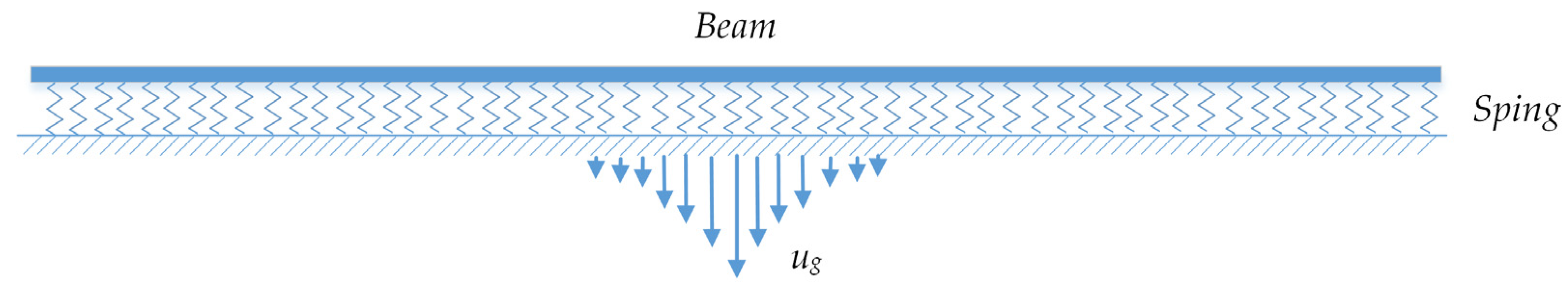
2.1. Beam Bending Response of the Beam on a Winkler Foundation

As shown in Figure 1, an arbitrary displacement of the free field can be discretized into the standard displacement ug. The response of the structure under an arbitrary displacement of the free field can be transformed into the superposition of a series of standard displacements, which has the form
u g x = 0 x < l g 0 l x l 0 x l
where g0 and l are the height and half the width of the standard displacement, respectively.
As illustrated in Figure 2, a long, linear underground structure embedded in a full-space foundation under the standard displacement can be simplified using a model of a Euler beam on a Winkler foundation. The Winkler elastic foundation model assumes that the foundation responds to the load on the beam in a linear elastic manner. For each position x along the beam axis, the beam experiences an elastic reaction force Fs(x) provided by the foundation. According to the Winkler model theory, the relationship between the elastic reaction force and the deflection is given by:
F s x = K h u g ( x ) u b x
where Kh is the Winkler foundation modulus, and ub is the beam displacement.
Based on Euler’s beam theory, the relationship between the bending moment of the beam and the deflection has the form
M x = E b I b d 2 u b x d x 2
where M(x) is the bending moment, Eb is the elastic modulus of the beam, and Ib is the moment of inertia of the beam’s cross-section.
The equilibrium equation of the beam element can be written as follows:
d Q x d x = F s
By using the relationship Q = dM/dx and combining Equations (2)–(4), the governing equation of the Euler beam on the Winkler foundation can be derived as follows:
d 4 u b d x 4 + 4 ξ 4 u b = 4 ξ 4 u g x
where
ξ = K h / 4 E b I b 4
Owing to the displacement of the free-field displacement from Equation (1) being divided into three segments, the response of the beam should be also represented by a three-segment function. However, this is not beneficial for the subsequent fitness to obtain the Winkler foundation modulus. Considering the displacement ug with a finite interval, it can be represented by the Fourier integral as follows:
u g x = g 0 π 0 2 sin λ l cos λ x λ d λ
Owing to assumptions that the beam and foundation deform within the linear range, the beam response can be solved using the linear superposition method. From Equation (7), it is clear that the response of the beam under the standard displacement ug(x) can be obtained by integrating the response of the beam under a cosine load g 0 π 2 sin λ l cos λ x λ . Thus, the free-field displacement can be assumed to be:
u g 1 x = a cos λ x
where a = g 0 π 2 sin λ l λ .
Substituting Equation (8) into Equation (4), the beam displacement under the free-field displacement from Equation (8) is obtained as follows:
u t 1 x = 4 a ξ 4 λ 4 + 4 ξ 4 cos λ x
Combining Equations (7)–(9), the beam displacement is obtained by
u t x = g 0 π 0 4 ξ 4 λ 4 + 4 ξ 4 2 sin λ l cos λ x λ d λ
The normalized displacement ut and normalized bending moment M of the beam have the forms
u t π g 0 = I b ξ x ¯ + κ I b ξ x ¯ κ
π M b 2 g 0 E b I = b ξ 2 J b ξ x ¯ + κ J b ξ x ¯ κ
κ = l b
x ¯ = x b
I x = 0 π 2 sin x tan t 2 tan t d t
J x = 0 π 2 sin x tan t 2 d t
Equation (12) can be solved using Gauss–Legendre numerical integration.

2.2. Beam Bending Response of the Beam on a Three-Dimensional Elastic Foundation

In this section, the response of the beam in the three-dimensional elastic foundation under the free-soil displacement is derived. The process of deduction is divided into three steps. In the first step, the displacement solution of the three-dimensional elastic foundation under the double cosine load q(x,y) is deduced. In the second step, the y-axis distributed force q0(y) of the dual cosine load q(x,y) is limited to a beam width range of [−b, b] and the relationship between the average force and displacement in a range of [−b, b] is obtained. In the third step, the beam is first subjected to an external cosine wave soil displacement. Then, based on the deformation relationship between the beam and the foundation, as well as the relationship obtained in the second step, the beam displacement under the external cosine wave soil displacement is derived. Finally, the beam response under standard displacement is obtained using a Fourier integral for the beam response under the cosine wave displacement.

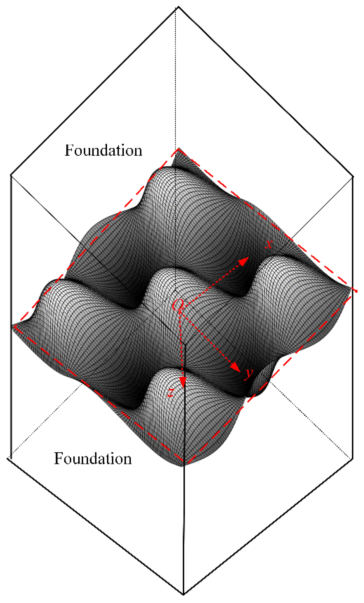
2.2.1. The Elastic Foundation under the Double Cosine Load

As shown in Figure 3, a double cosine load is applied on the middle plane of the full-space foundation, which is expressed as
q x , y = q 0 cos λ x cos ω y
The governing equation of the foundation has the form
Δ 2 u + 1 1 2 ν s e x = 0 Δ 2 v + 1 1 2 ν s e y = 0 Δ 2 w + 1 1 2 ν s e z = 0
where u, v, and w are the displacements along the x, y, and z axes, respectively, and νs is the Poisson’s ratio for the ground:
e = u x + ν y + w z
The solution of Equation (18) under the load expressed by Equation (17) should satisfy the following conditions: (1) the expression of the solution is the cosine function for x and y; (2) the shear stress and normal stress are zero and continuous, respectively, in the plane xoy; (3) the displacement along z is continuous in the plane xoy; (4) the stress reaches zero when z approaches infinity. According to the study by Yu et al. [19], the general solution has the form
u = U z sin λ x cos ω y
v = V z cos λ x sin ω y
w = W z cos λ x cos ω y
where
U z = a 1 + a 2 z e z λ 2 + ω 2 + a 3 + a 4 z e z λ 2 + ω 2
V z = U z ω λ
W z = 2 2 ν s λ λ 2 + ω 2 U 3 2 ν s λ U
where a1a4 are the undetermined coefficients.
The undetermined coefficients can be obtained using conditions (2)–(4). Substituting the undetermined coefficients into Equation (22), the solution can be expressed as follows:
w x , y , z = 1 + ν s 2 E s q 0 cos λ x cos ω x z + 2 2 ν s λ 2 + ω 2 e z λ 2 + ω 2
where Es is the elastic modulus of the ground.
It is evidently deduced that the relation between the displacement w0 and q at z = 0 has the form
w 0 = 1 ν s 2 E s q λ 2 + ω 2

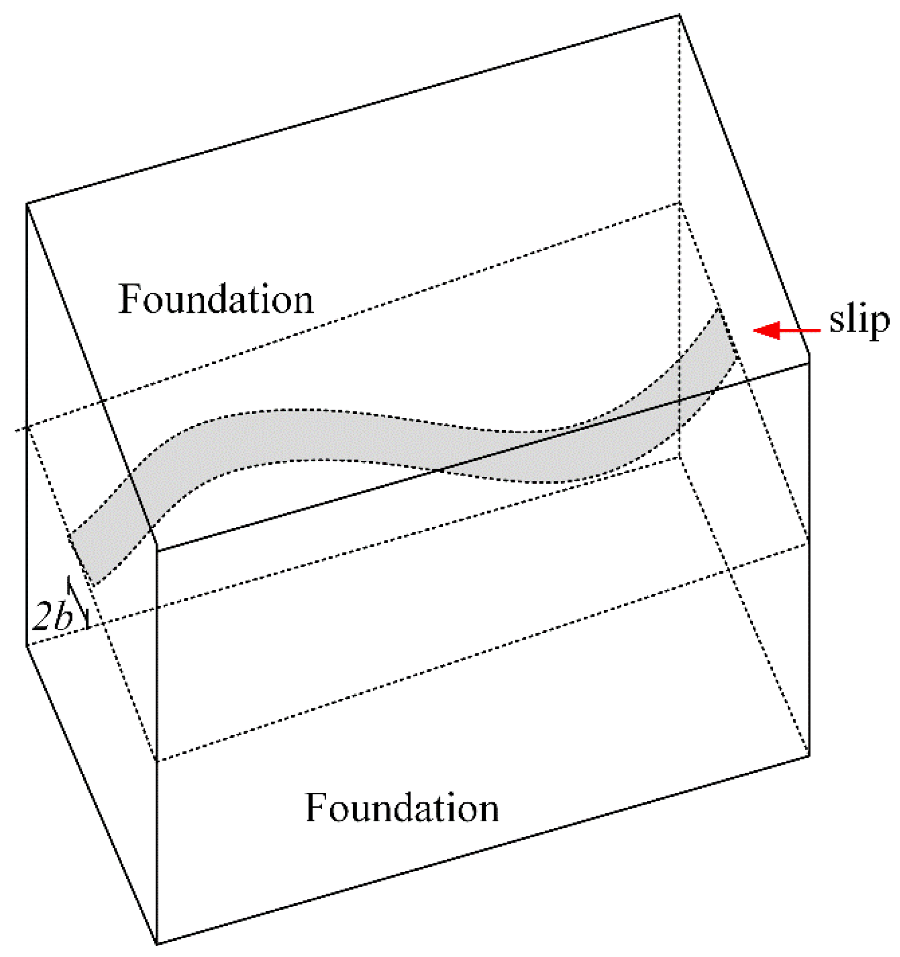
2.2.2. The Response of the Foundation under a Single Cosine Load

When considering a beam with a limited width, it is necessary to calculate the foundation response within the range of the beam’s width. The average value of the y-distributed force q0(y) of the double cosine load q(x, y) in the interval [−b, b] is calculated to obtain the single cosine load. As shown in Figure 4, the foundation is subjected to a single cosine load in the interval [−b, b], which can be written as follows:
q s x , y = q 0 y cos λ x
where
q 0 y = 0 y < b q 0 b y b 0 y > b
It should be noted that the term q0(y) can also be represented by the Fourier integral, as follows:
q 0 ( y ) = q 0 π 0 2 sin ( ω b ) cos ω y ω d ω
When a load by the expression in Equation (28) acts on the foundation, the displacement of the foundation should have a similar cosine expression, as follows:
w s x , y = w 0 y cos λ x
Moreover, the concentrated load Qavg and average displacement Wavg have the forms
Q a v g = b b q s x , y d y
W a v g = 1 2 b b b w s x , y d y
Combining Equations (27)–(33), the relationship between force Qavg and displacement Wavg can be obtained as follows:
Q a v g = W a v g 2 E s C 1 ν s 2 β ψ β
where C = 1.1, from the research by [14]; β = ; and
ψ x = π 2 0 π / 2 s i n 2 x t a n t x s i n t t a n t d t

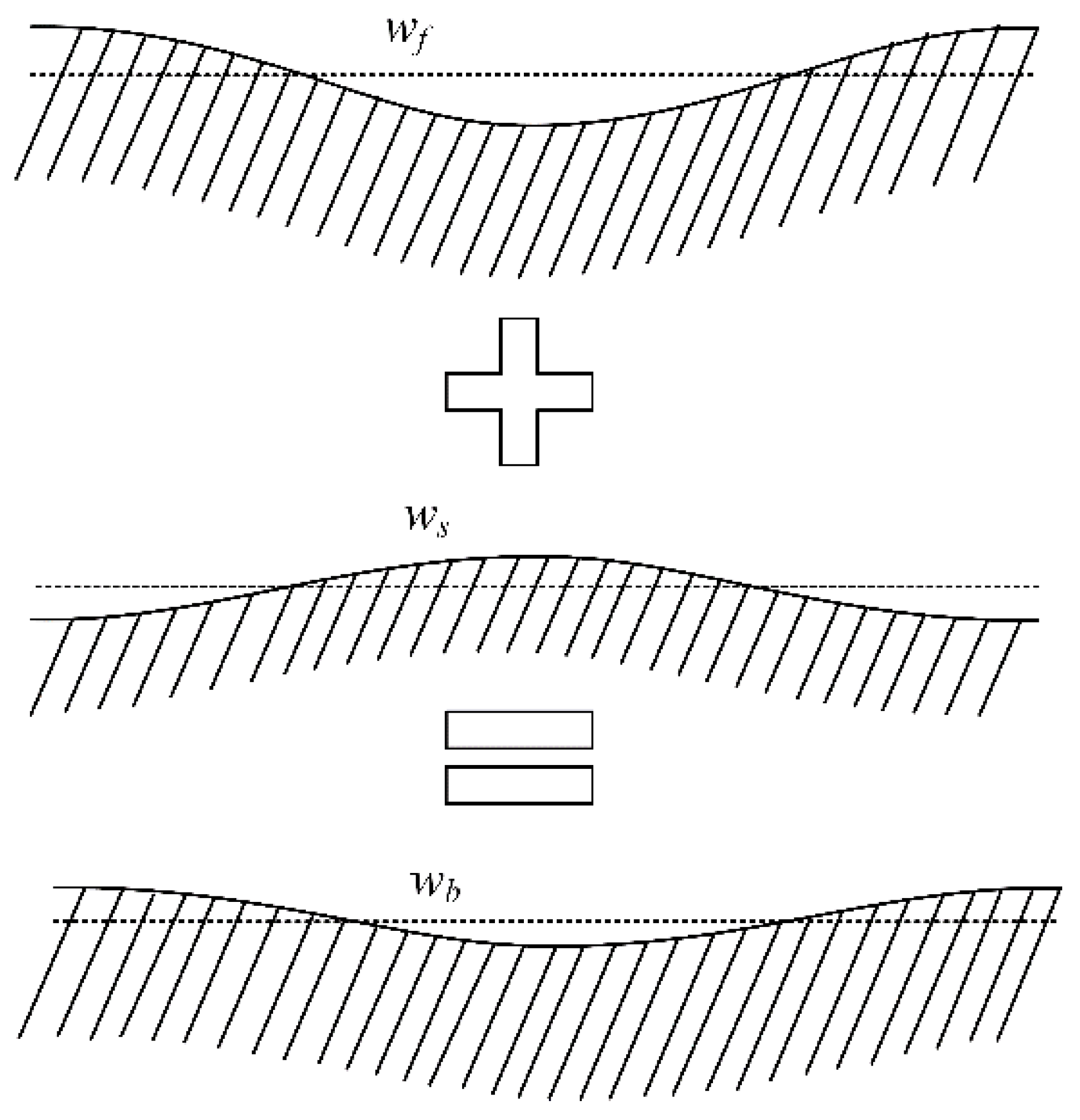
2.2.3. The Response of the Beam under Unit Bar Displacement

Underground structures, such as tunnels, are subject to free-field deformation. The displacement of the free field is assumed to be wf from Equation (8). The contact force at the interface of the beam and foundation has the form
Q a v g = Q a v g f c o s λ x
where Qavgf is amplitude.
According to the theory of the elastic beam, when the load expressed by Equation (36) is applied to the beam, the deformation of the beam satisfies the following expression:
w b = Q a v g E b I b λ 4
Using the relationship derived from Equation (34), the displacement of the ground under the force given by Equation (36) has the form
w s = Q a v g C 1 ν s 2 E s β ψ β
As shown in Figure 5, the displacement of the beam and ground should meet the displacement coordination. Thus, the following expression is given:
w b = w f + w s
The term Qavg is eliminated by combining Equations (37) and (38). By using the result in Equation (39), the displacement of the beam is obtained as follows:
w b = a cos λ x C 1 ν 2 E b I b E s β λ 4 ψ β + 1
By using Fourier integration on Equation (40), the displacement response of the beam under the unit bar displacement shown in Figure 1 can be written as follows:
w b x = g 0 π 0 1 λ 2 sin λ l cos λ x C 1 ν 2 E b I b E s 2 β λ 4 ψ β + 1 d λ
The normalized displacement and bending moment of the beam under displacement can be derived as follows:
w π s 0 = 0 2 sin m η κ cos m η x ¯ η 4 2 ψ m η + η d η
M π b 2 s 0 E b I b = m 2 0 2 sin m η κ cos m η x ¯ η 2 2 ψ m η + 1 η d η
where
c 3 = C 1 ν 2 E b I b E s b
m = E s b 4 / C 1 ν 2 E b I b 3
η = c λ

2.3. The Fitting Expression of the Winkler Foundation Modulus

A fitting method was adopted by Vesic [16] to obtain the Winkler foundation modulus. The detailed process can be divided into three steps. The core goal of Vesic’s method is to ensure that the displacements, rotations, bending moments, and shear forces obtained from the two methods have similar overall shapes, but it does not aim to achieve equal maximum bending moments. Since the second derivative of the bending moment is related to displacement, this fitting goal can be achieved by ensuring that the first zero of the bending moment obtained from the two methods is equal. It is worth noting that when κ is small enough, the first zero point of the bending moment derived from Equation (43) is independent of κ, which has been proved by Yu et al. [20].
The detailed process can be divided into three steps. In the first step, m is assumed to be within the range of 0.01 to 1. Based on the assumed m, the first zero point x ¯ 0 of the bending moment from Equation (43) is obtained. In the second step, is obtained using Equation (12) based on the given x ¯ 0 . In the third step, the relationship function between m and is established through data fitting, and the Winkler foundation modulus can be easily obtained by solving the relationship function. The related data are listed in Table 1.
Fitting the data in Table 1, the relationship function of m and is obtained as follows:
1.5873 E s b 4 / C 1 ν s 2 E b I b 3 0.85 = K h b 4 / ( E b I b ) 4
and C 1 ν s 2 0.13 approaches 1 for different ν s . Thus, Equation (37) can be simplified as follows:
K h = 4.02 E s 1 ν s 2 E s B 4 E b I 0.13
where B is the width of the beam, having the expression 2b.

3. Verification

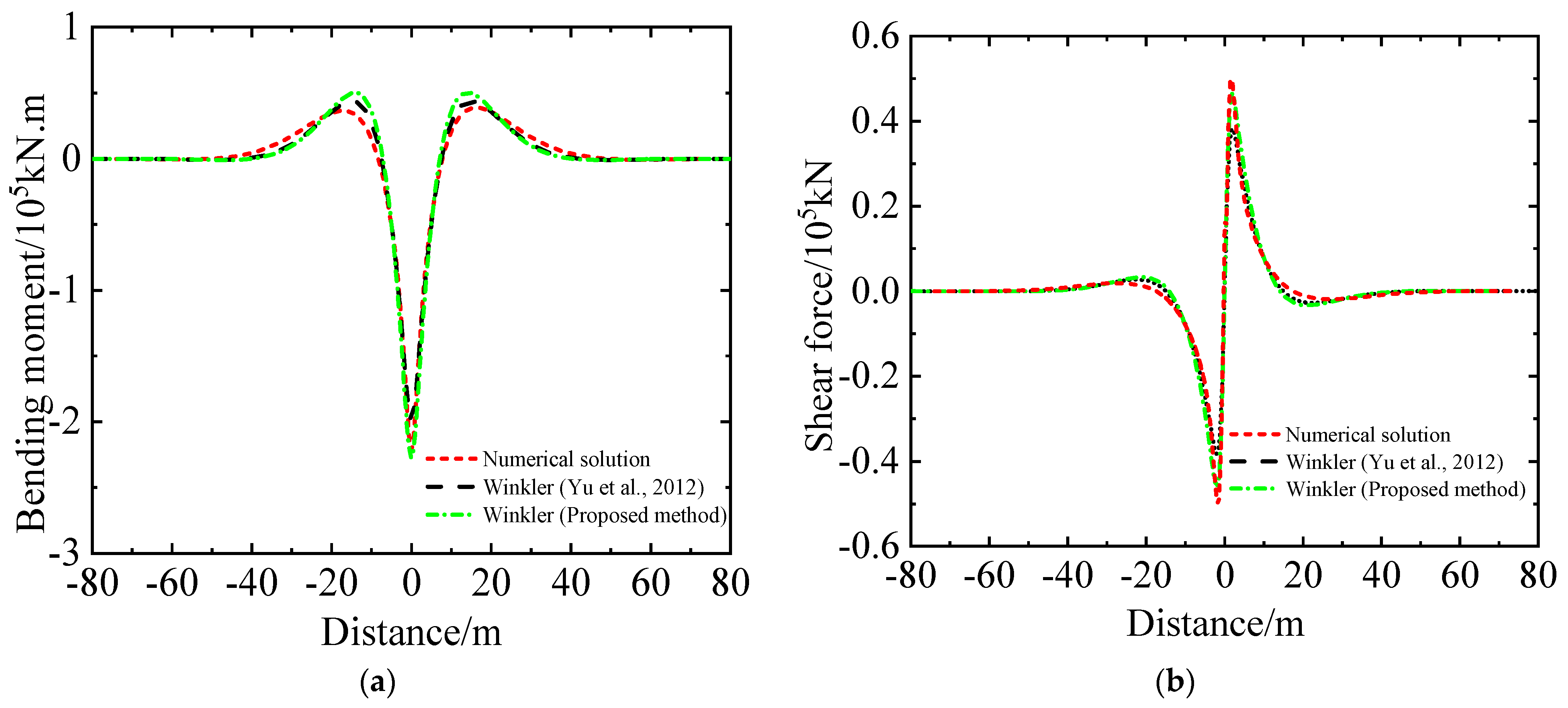
3.1. Numerical Verification

In this subsection, the solutionsfrom the beam–spring model using the proposed Winker foundation modulus and the Winker foundation modulus proposed by Yu et al. [20] are compared with three-dimensional solid finite element solutions obtained from ABAQUS.
As shown in Figure 6, a three-dimensional solid finite element model is built. The model has a length of 160 m, a width of 80 m, and a height of 80 m. Meanwhile, the beam has an outer diameter of 6.2 m and an inner diameter of 5.5 m. In the middle of the model, the model grid is set as 1 m along the x-axis. The other parts are sparsely meshed. The same mesh method is applied to the section grid of the model. The ground has a shear modulus of 50 Mpa and a Poisson’s ratio of 0.38. The elastic modulus and Poisson’s ratio of the beam are 34.5 Gpa and 0.2, respectively. The contact state at the beam–ground interface is a ‘slip’ state. The free-field displacement has the form u g x = 0.1 e 1 2 x 2 , which was obtained from the research of Zhang et al. [23] and is applied to the boundaries of the model.
The beam–spring numerical model obtained from ABAQUS is plotted in Figure 7, wherein the beam is modeled using a Euler beam, which rests on a series of springs. The beam is meshed at 0.1 m. The values of the spring are calculated using the proposed formula for the Winkler foundation modulus and that by Yu et al. [20]. The free-field displacement is input at the far end of the spring. The material parameters of the beam are the same as those used in the three-dimensional solid finite element model.
For further explanation, a relative error is defined as (CeCa)/Ce, in which Ce is the peak response of the beam from the numerical model, as well as the peak response Ca obtained from the model of an Euler beam on the Winkler modulus.
Figure 8 illustrates the displacement distribution along the beam axis. It is evident that compared with numerical solutions obtained using the solid finite element model, the displacement obtained using the proposed Winkler foundation modulus performs better than those from the Winkler foundation modulus of Yu. To be specific, the beam’s displacements using the proposed Winkler foundation modulus and Winkler foundation modulus by Yu have errors of 6.15% and 12.29%, respectively. Figure 9 shows the shear force and bending moment response of the beam obtained using different methods. Evidently, compared with the results obtained using the Winkler foundation modulus by Yu, the results adopting the proposed Winkler foundation modulus are closer to the numerical solutions, as for both bending moment and shear force. In detail, compared with the numerical solution, the errors for solutions using the Winkler foundation modulus obtained by Yu are 10.81% for the bending moment and 23.6% for the shear force, respectively. However, the corresponding errors using the proposed Winkler foundation modulus are 2.25% and 7.20%, respectively, which are quite small.

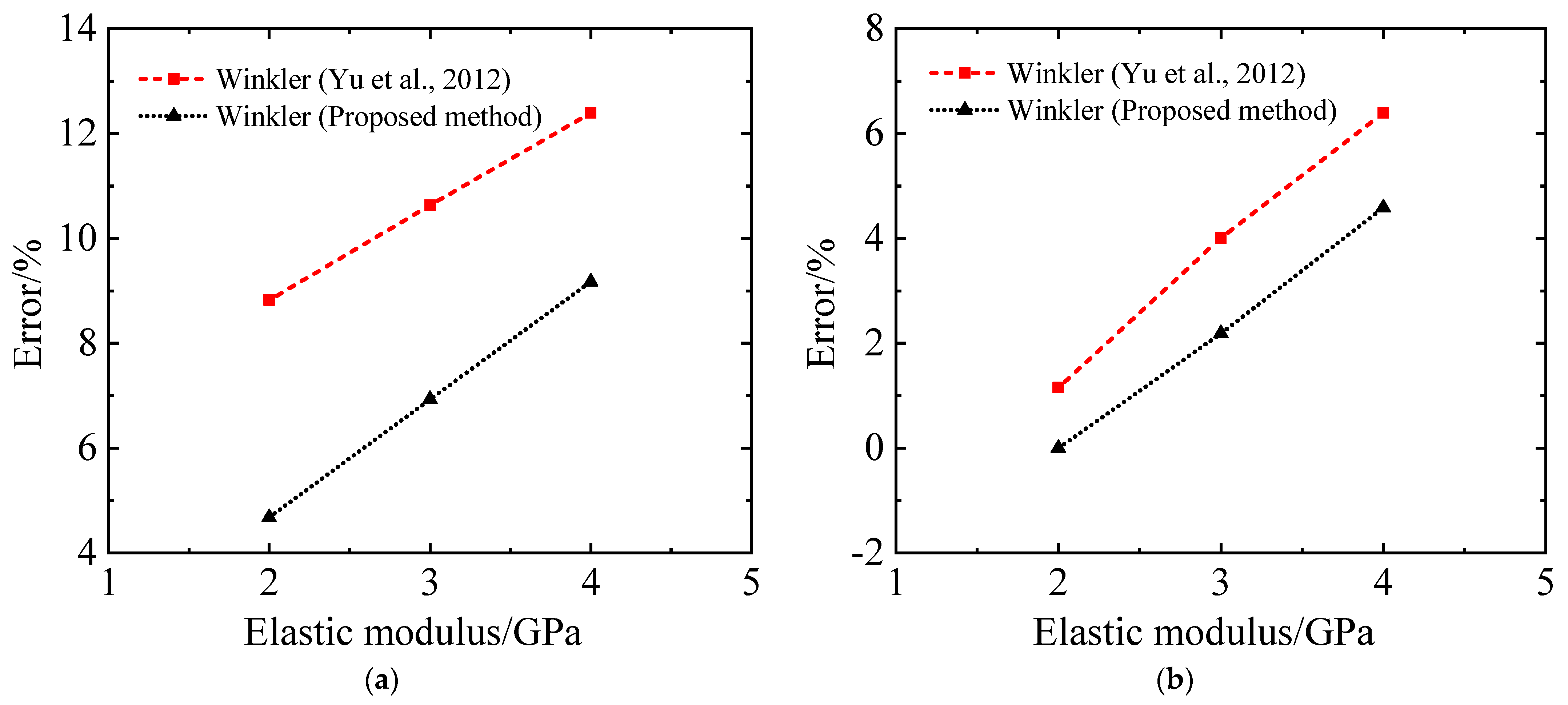
3.2. Comparison with Previous Research

An analytical solution for the tunnel’s response under fault creep was proposed by Zhao et al. [24], wherein a model with a Timoshenko beam resting on the Winkler foundation was used to obtain the analytical solution. The foundation modulus by Yu et al. [20] was used in Zhao’s research. In this subsection, the tunnel’s responses under fault creep are obtained based on the analytical solution obtained by Zhao using the proposed Winkler foundation modulus and Yu’s Winkler foundation modulus. Meanwhile, the corresponding numerical solutions obtained using the solid finite element model in ABAQUS are also given to calculate the errors.
The elastic modulus of the fixed and moving block is set to 2 GPa, 3 GPa, and 4 GPa, respectively. The corresponding Poisson’s ratio is set as 0.32. Meanwhile, the fault zone has an elastic modulus of 1 GPa and a Poisson’s ratio of 0.35. The tunnel has an outer radius of 3.1 m and a thickness of 0.35 m. The other parameters are the same as those in the work by Zhao et al. [24]. By comparing with the numerical solution, the errors of internal force from the analytical solutions are given below.
Figure 10 gives the errors of the peak internal force response of the tunnel along the tunnel’s axis under fault creep. Regardless of bending moment and shear force, the errors of the analytical solutions by the proposed Winkler foundation modulus are smaller than those of Yu’s Winkler foundation modulus. In detail, the error for the bending moment in Yu’s Winkler modulus exceeds 10% for elastic moduli of 3 GPa and 4 GPa. The errors for the bending moment using the proposed Winkler modulus are all less than 10% for different cases. In terms of shear force, the errors of the analytical solution obtained using the proposed Winkler foundation modulus slightly decrease.
Figure 8, Figure 9 and Figure 10 show that the accuracy of the Winkler foundation modulus determined by the fitting solutions of the Euler beam on the Winkler foundation and the beam on the three-dimensional elastic foundation, disregarding tangential interactions, is notably higher than that obtained using Yu’s method, in which the tangential interaction is ignored in the elastic foundation model but considered in the model with a beam on the three-dimensional elastic continuum foundation.

4. Conclusions

The elastic foundation beam model is widely used to obtain the responses of underground structures. The Winkler foundation modulus is key to determining the accuracy of the Winkler foundation modulus. In this paper, an improved Winkler foundation modulus using a full space is deduced, wherein the Winkler foundation modulus is obtained by fitting the bending moment from an elastic foundation beam model and a beam on a three-dimensional elastic foundation. Since the Winkler foundation modulus is only related to the normal interaction between the beam and the foundation, when solving the bending response based on the beam on the Winkler foundation and three-dimensional elastic foundation, only the normal action between the beam and the foundation should be considered, and the tangential action that affects the bending response of the beam should be ignored. By comparison with numerical solutions and previous studies, the proposed Winkler foundation modulus is verified. The proposed Winkler foundation modulus has a higher accuracy than the previous Winkler foundation modulus because the tangential interaction between the beam and the ground is ignored in the solution process. The proposed Winkler foundation modulus can be used to evaluate the responses of underground tunnels, especially tunnels with deep burial depths.

Author Contributions

Conceptualization, L.X. and X.D.; methodology, L.X., M.Z. and J.H.; software, L.X.; validation, L.X., J.H. and H.L.; data curation, J.H.; writing—original draft preparation, L.X. and J.H.; writing—review and editing, M.Z.; visualization, X.Z. and S.C.; supervision, X.D.; project administration, X.D. All authors have read and agreed to the published version of the manuscript.

Funding

This research was funded by the National Natural Science Foundation of China (52378475), the National Key Research and Development Program of China (2022YFC3004305, 2022YFC3004304), the Postdoctoral Research Foundation of China (2023M730200), and the Beijing Postdoctoral Research Foundation (2023-zz-A135), which are gratefully acknowledged.

Institutional Review Board Statement

Not applicable.

Informed Consent Statement

Not applicable.

Data Availability Statement

The relevant data are all included in the paper.

Conflicts of Interest

Author Shengtao Cao was employed by the company Guangzhou Yingli Technology Ltd. The remaining authors declare that the research was conducted in the absence of any commercial or financial relationships that could be construed as a potential conflict of interest.

References

  1. Winkler, E. Die Lehre von der Elastizität und Festigkeit; Dominicus: Prague, Czech Republic, 1867. [Google Scholar]
  2. Xu, Z.; Li, J.Q. Application of K30 test method in engineering survey of rock-soil for Shenzhen Metro. J. Railw. Eng. Soc. 2007, 12, 90–94. (In Chinese) [Google Scholar]
  3. Cheng, D.A.; Mao, J.F. Test methods for laboratory foundation bed coefficient. Chin. J. Geotech. Eng. 2011, 33, 281–284. (In Chinese) [Google Scholar]
  4. Zhang, W.; Zhang, B.; Zhang, S.Q. Evaluating coefficient of subgrade reaction by statically tests and its application. Geotech. Eng. Tech. 2016, 30, 78–84. (In Chinese) [Google Scholar]
  5. Zhang, J.J.; Guo, Z.; Zhang, L.H. The research on test method of laboratory subgrade coefficient. Geotech. Eng. Tech. 2017, 31, 289–293. (In Chinese) [Google Scholar]
  6. Li, W.; Igoe, D.; Gavin, K. Evaluation of CPT-based P—Y models for laterally loaded piles in siliceous sand. Geotech. Lett. 2014, 4, 110–117. [Google Scholar] [CrossRef]
  7. Dash, S.R.; Bhattacharya, S. Experimental p-y curves for liquefied soils from centrifuge tests. Earthq. Eng. Eng. Vib. 2021, 20, 863–876. [Google Scholar] [CrossRef]
  8. Vakili, A.; Zomorodian, S.M.A.; Totonchi, A. Small scale medel test on lateral behaviors of pile group in loose silica sand. Acta Geotech. Slov. 2021, 18, 41–54. [Google Scholar] [CrossRef]
  9. Siemaszko, P.; Meyer, Z. Static load test cure analysis based on soil field investigations. Bull. Pol. Acad. Sci. Tech. Sci. 2019, 67, 329–337. [Google Scholar]
  10. Santrac, P.; Susic, N.; Bajic, Z. Determination of the Pile Stiffness Matrix Based on the Pile Load Test Results and the Effect of Pile Interaction. Teh. Vjesn. 2020, 27, 2016–2023. [Google Scholar]
  11. Sheldon, T.; Sezen, H.; Moore, D. Beam-on-Springs Modeling of Jointed Pipe Culverts. J. Perform. Constr. Facil. 2016, 30, 04015002. [Google Scholar] [CrossRef]
  12. Zhang, L.; Gao, G.Y.; Gao, M. Discussion on the calculation method of coefficient of subgrade reaction. Chin. J. Undergr. Space Eng. 2011, 7, 812–818. (In Chinese) [Google Scholar]
  13. Li, Y.M.; Wang, L.; Liu, Y.B.; Liu, L.P. Analysis of methods for determining the spring constant of ground foundation in seismic design of underground structures. J. Earthq. Eng. Eng. Vib. 2012, 32, 106–113. [Google Scholar]
  14. Biot, M.A. Bending of an infinite beam on an elastic foundation. J. Appl. Mech. ASME 1937, 59, A1–A7. [Google Scholar] [CrossRef]
  15. Terzaghi, K. Evalution of conefficients of subgrade reaction. Geotechnique 1955, 5, 297–326. [Google Scholar] [CrossRef]
  16. Vesic, A.B. Bending of beams resting on isotropic elastic solid. J. Eng. Mech. Div. 1961, 87, 35–53. [Google Scholar] [CrossRef]
  17. Daloglu, A.T.; Vallabhan, C. Values of k for slab on Winkler foundation. J. Geotech. Geoenviron. Eng. 2000, 126, 463–471. [Google Scholar] [CrossRef]
  18. Klar, A.; Vorster, T.; Soga, K.; Mair, R.J. Soil—Pipe interaction due to tunnelling: Comparison between Winkler and elastic continuum solutions. Geotechnique 2005, 55, 461–466. [Google Scholar] [CrossRef]
  19. Yu, J.; Zhang, C.; Huang, M. Soil—Pipe interaction due to tunnelling: Assessment of Winkler modulus for underground pipelines. Comput. Geotech. 2013, 50, 17–28. [Google Scholar] [CrossRef]
  20. Yu, J.; Zhang, C.; Huang, M. Subgrade modulus of underground pipelines subjucted to soil movements. Chinses J. Rock Mech. Eng. 2012, 31, 123–132. (In Chinese) [Google Scholar]
  21. Zhao, M.; Jiao, H.; Huang, J.; Li, H.; Du, X.; Wang, J. Analytical solutions for circular tunnels under longitudinally propagating shear waves based on improved foundation beam models considering tangential interaction. Tunn. Undergr. Space Technol. 2022, 123, 104444. [Google Scholar] [CrossRef]
  22. Zhao, M.; Li, H.; Huang, J.; Du, X.; Wang, J.; Yu, H. Analytical solutions considering tangential contact conditions for circular lined tunnels under longitudinally propagating shear waves. Comput. Geotech. 2021, 137, 104301. [Google Scholar] [CrossRef]
  23. Zhang, K.Y.; Wang, Y.; Ai, Y.B. Analytical solution to interaction between pipelines and soils under arbitrary loads. Chin. J. Geotech. Eng. 2010, 32, 1189–1193. (In Chinese) [Google Scholar]
  24. Zhao, M.; Xu, L.; Huang, J.; Du, X.; Li, H. Analytical solutions of the tunnels under the fault creeping by elastic foundation beam model with considering tangential interaction. Soil Dyn. Earthq. Eng. 2023, 172, 108047. [Google Scholar] [CrossRef]
Figure 1. Displacement of the free field.
Applsci 14 02277 g001
Figure 2. Euler beam on the Winkler foundation.
Applsci 14 02277 g002
Figure 3. A double cosine load applied on the plane xoy.
Applsci 14 02277 g003
Figure 4. A simple cosine load acting on a foundation.
Applsci 14 02277 g004
Figure 5. Displacement coordination of the beam and ground.
Applsci 14 02277 g005
Figure 6. Three-dimensional solid finite element model.
Applsci 14 02277 g006
Figure 7. Beam–spring numerical model.
Applsci 14 02277 g007
Figure 8. Beam displacement along the axis obtained via different methods [20].
Applsci 14 02277 g008
Figure 9. Beam internal forces along the axis obtained using different methods (a) bending moment; (b) shear force [20].
Applsci 14 02277 g009
Figure 10. The errors of the tunnel’s peak internal forces along the axis using different elastic moduli: (a) bending moment; (b) shear force [20].
Applsci 14 02277 g010
Table 1. Fitting data from the two methods.
m x ¯ 0
0.0135.720.032
0.02516.730.067
0.0411.430.098
0.059.390.119
0.076.940.161
0.15.060.220
0.124.40.253
0.22.810.396
0.252.270.490
10.571.949
Disclaimer/Publisher’s Note: The statements, opinions and data contained in all publications are solely those of the individual author(s) and contributor(s) and not of MDPI and/or the editor(s). MDPI and/or the editor(s) disclaim responsibility for any injury to people or property resulting from any ideas, methods, instructions or products referred to in the content.

