Article

Spatial and Momentum Mapping Modes for Velocity Map Imaging Spectrometer

1
School Physical Science and Technology, ShanghaiTech University, Shanghai 201210, China
2
Center for Transformative Science, ShanghaiTech University, Shanghai 201210, China
*
Author to whom correspondence should be addressed.
Appl. Sci. 2024, 14(5), 2190; https://doi.org/10.3390/app14052190
Submission received: 4 February 2024 / Revised: 24 February 2024 / Accepted: 27 February 2024 / Published: 6 March 2024
(This article belongs to the Special Issue New Science Opportunities at Short Wavelength Free Electron Lasers)

Abstract

:
The velocity map imaging (VMI) technique is used to acquire the momentum distribution of charged particles. Here, we introduce two additional operation modes for our recently built velocity map imaging (VMI) spectrometer: the spatial mapping mode that magnifies the image of zero energy ions with different scales and the high-resolution momentum mapping mode that acquires the electron momentum distribution at the kinetic energy of about 100 eV. In simulations, the ion image is magnified with a factor of up to 7.6, and a relative resolution of 0.15% at 150 eV electron kinetic energy is predicted. Switching between these two modes helps reduce the alignment error to below 0.2 mm. In the test using the above-threshold ionization (ATI) of argon (Ar), the Ar+ ion image is magnified by a factor of up to 6.7, and a relative resolution of 1.3% at 44.6 eV electron kinetic energy is achieved.

1. Introduction

The velocity map imaging (VMI) technique aims to acquire the momentum distribution of charged particles. In 1987, Chandler and Houston introduced the ion imaging technique to project the 3D momentum distribution of CH 3 + onto a 2D image detector [1]. A 2D image detector typically consists of a microchannel plate (MCP) pair followed by either a phosphor screen with a camera or alternatively a delay line anode with electronic system. Ten years later, Eppink and Parker improved momentum resolution with a focusing lens [2]. With this lens, the charged particles with the same initial radial momentum will arrive at the detector at almost the same radius, insensitive to their initial positions. So, the blur on the image due to the source volume is significantly reduced and the momentum resolution is greatly improved. The maximum detectable energy is set by the voltages applied to the spectrometer electrodes. The VMI technique provides a 4 π solid collection angle, and the high efficiency is typically only limited by the detector. Based on the kinetic energy spectrum and angular distribution, the ionization and dissociation processes of atoms, molecules, and clusters can be explored. As a result, the VMI spectrometers have been widely used in the photoionization and photodissociation experiments over the past several decades [3,4,5,6,7,8]. Since achieving a higher imaging resolution and magnification capabilities is always desired, many lenses have been developed to improve the relative energy resolution at low kinetic energy [9] and extend the electron energy limit up to keV [10,11].
In the experiment, it is important to put the laser focus as close as possible to the VMI reaction center to improve the resolution. Moreover, the pump-probe technique has been employed for the real-time monitoring of reactions [12,13,14,15,16,17,18]. The difficulty of alignment is further increased because one needs to find the spatial–temporal overlap between the pump and probe pulse. Thus, it would be advantageous to view the focus points of two laser pulses directly from the detector as precisely as possible, especially during the very limited beamtime at a large research facility [19]. Even when a single laser pulse is used, the reaction rate can be sensitive to the intensity variation in the source region. Thus, a source-position resolved measurement will be more precise than a source-position integrated one [20,21]. In such cases, spatial map imaging mode is developed and detailed [22]. It would be beneficial to establish both velocity and spatial mapping of the ionization within the same spectrometer [23].
In the previous paper [11], we achieved a 1.5% relative electron energy resolution at 500 eV. To explore its performance at a lower but much more widely used kinetic energy, i.e., 100 eV, we develop two additional working modes for the velocity map imaging (VMI) spectrometer: the spatial mapping mode and high-resolution momentum mapping mode.

2. Apparatus

Since the spectrometer was detailed in ref. [11], we provide only a summary here. Figure 1 shows a diagram of the spectrometer. It consists of five chambers: (i) the source chamber, (ii) the first differential chamber, (iii) the second differential chamber, (iv) the main chamber, and (v) the jet dump chamber. A piezo valve (Amsterdam Cantilever ACPV2, Amsterdam, The Netherlands) [24] with a pinhole of 100 μm diameter is installed to produce a supersonic molecular beam in the source chamber. The piezo valve backing pressure is set at 1.0 bar. After passing the 1st and the 2nd differential chambers equipped with 1 mm diameter holes, the molecular beam enters the main chamber of the VMI spectrometer, where it encounters either the X-ray photon or femtosecond laser. The diameter of the gas jet is estimated as 1.2 mm according to the mechanical structure. A double-layered μ -metal shield is installed to reduce the residual magnetic field at the interaction region to 8 mGs. Particles from the interaction region are focused by the lens system onto the two vacuum imaging detectors (VID275) from Photek, East Sussex, UK.
Each detector consists of two multi-channel plates (MCPs) with an active diameter of 75 mm and a P46 phosphor screen. Two Andor Zyla 4.2 Plus cameras from Oxford Instruments, Oxford, UK (2048 × 2048) are used to capture images of ions and electrons, respectively.
The lens system consists of 27 electrodes with voltages that can be adjusted individually from outside the vacuum chamber. A work fixture is used to assemble all electrodes into a whole set so that the possible misalignment is below 0.1 mm. The detailed geometry of the lens system can be found in Ding et al. [11]. By adjusting electrode voltages individually, we can add more working modes without changing the VMI lens structure, and different working modes can be easily switched back and forth using a computer-controlled high-voltage supply. Unfortunately, because the center the ion detector is worn out, we have to use the electron arm to demonstrate all the operation modes. As shown in Figure 2, the electron arm consists of 15 electrodes. Although it is already known that meshes can degrade the ( p x , p y ) image due to the microlensing effect [2], we installed two ultrafine stainless-steel meshes at the repeller electrode and the ninth extractor electrode for three reasons: keep an effusive gas jet using a hollow needle, focus three-dimensional ( p x , p y , p z ) for the future upgrade, and run both the electron arm and the ion arm simultaneously. The mesh has a density of 180 lines per inch and a transparency of 80% to effectively alleviate the microlensing effect.

3. Simulation

We performed simulations using SIMION software (version 8.2) [25] to magnify the ion image and optimize the electron resolution, respectively.

3.1. Spatial Mapping Mode

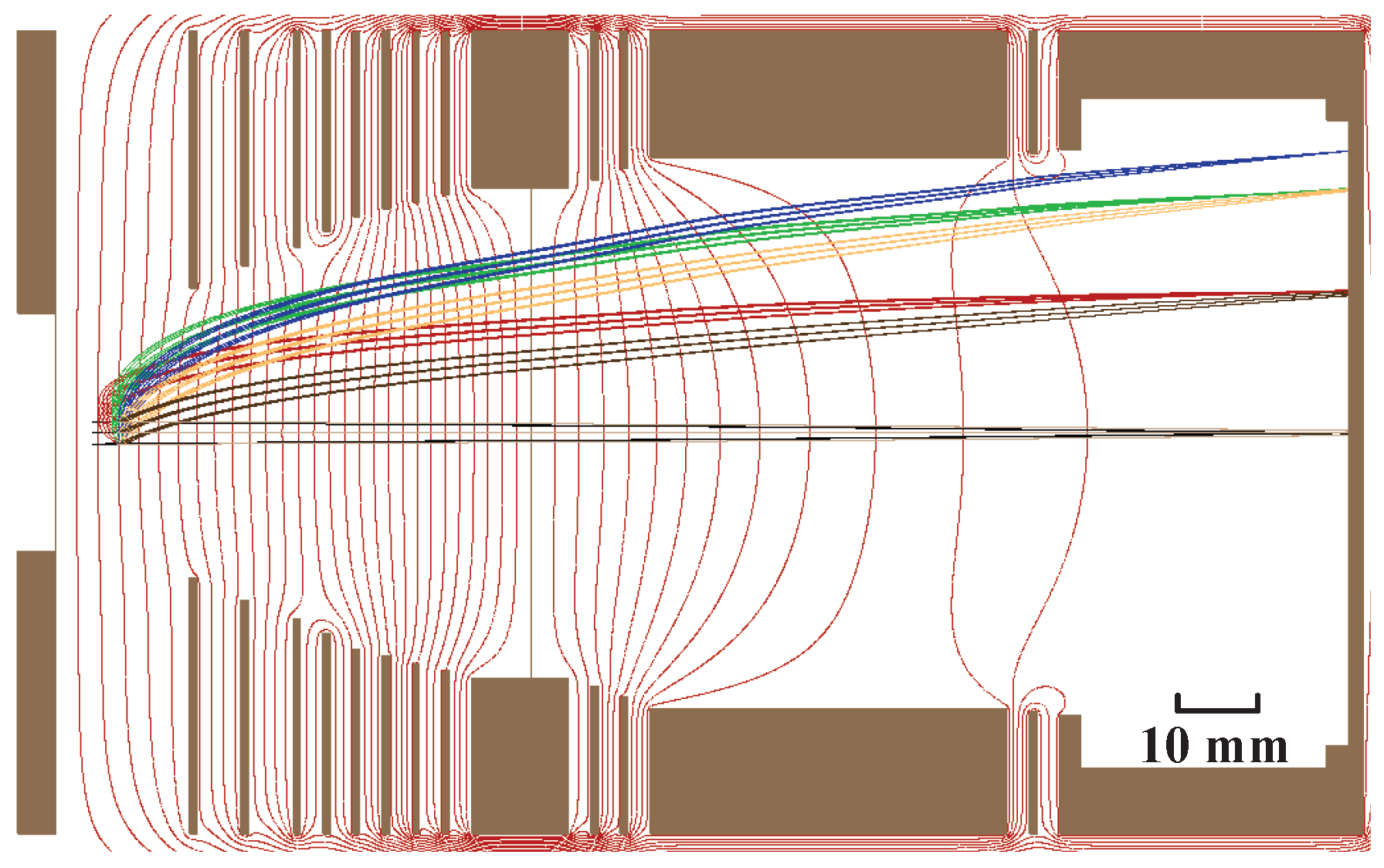
The spatial mapping mode is implemented to magnify the image of the zero kinetic energy ions with different scale factors. The interaction region is defined as a 3 × 9 point array in a 1 × 3 mm2 region, which is larger than the interaction region defined by the laser beam waist of 68 μm and the gas jet diameter of 1.2 mm. For a scaled factor, several hundred thousand iterations are needed to reach the linearly zoomed image. So, the simplified source definition is preferred rather than the various complicated distributions predefined in SIMION. Multiple simulations are conducted to achieve magnification factors of 2.2, 2.8, 5.9, and 7.6. The distance of the electrodes to the reaction region, the thicknesses and the inner diameter of each electrode, and the values of electrode voltages are summarized in Table 1. For larger scale factors, ions are decelerated more between electrodes 9 and 10, which may result in a larger microlens effect [26]. Figure 2 shows the simulated ion flight trajectory at the magnification factor of 7.6.
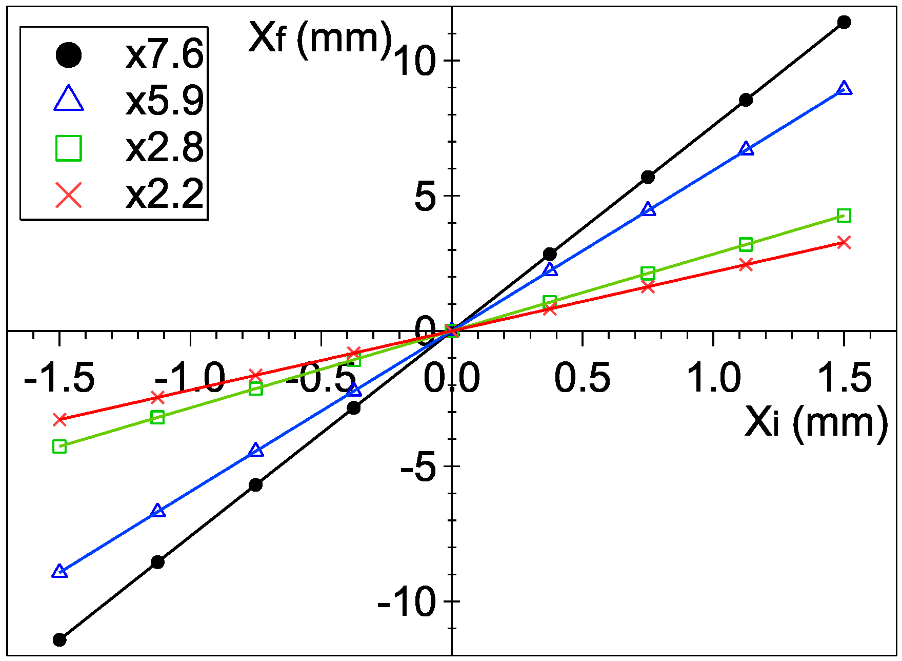
In order to check the linearity in the magnification, we plot the final position X f against the initial position X i in Figure 3 for all the magnification factors. Then, we fit each data set with a function:
X f = k 1 X i + k 2 X i 3 .
where k 1 and k 2 are the coefficients. The even-order terms are excluded due to the rotational symmetry. The fitting results are ( k 1 , k 2 ) = ( 2.18 , 1.03 × 10 3 ), ( 2.84 , 1.53 × 10 3 ), ( 5.93 , 1.15 × 10 2 ) and ( 7.58 , 1.54 × 10 2 ), respectively, which indicates excellent linearity in the magnification. The linear magnification in the spatial mapping mode guarantees low distortion in the acquired image.

3.2. High-Resolution Momentum Mapping Mode

The optimization in the previous paper [11] was for 1000 eV electrons, which is called high-energy mode. However, VMI is mainly used for measuring electrons within tens of eV kinetic energy. So, we add the working mode for the electrons with kinetic energy up to 150 eV, which is called the middle-energy mode. The resolution is sacrificed in high-energy mode due to the upper limit of the applicable high voltage. This sacrifice is unnecessary in the middle-energy mode, so we expect a better resolution. With the electron kinetic energy upper limit decreases, we can reduce all voltages proportionally.
Figure 4 illustrates the simulated electron-flying trajectory. The source region is defined by a 3 × 3 point array in a 1 × 3 mm2 region. The kinetic energy of electrons is 150 eV. The emission angle ranges from 0 to 180° with an interval of 30°. We calculate the spread of each electron cloud on the detector for every emission angle. The goal is set as the sum of them, and then we reduce this goal as much as possible in the optimization.
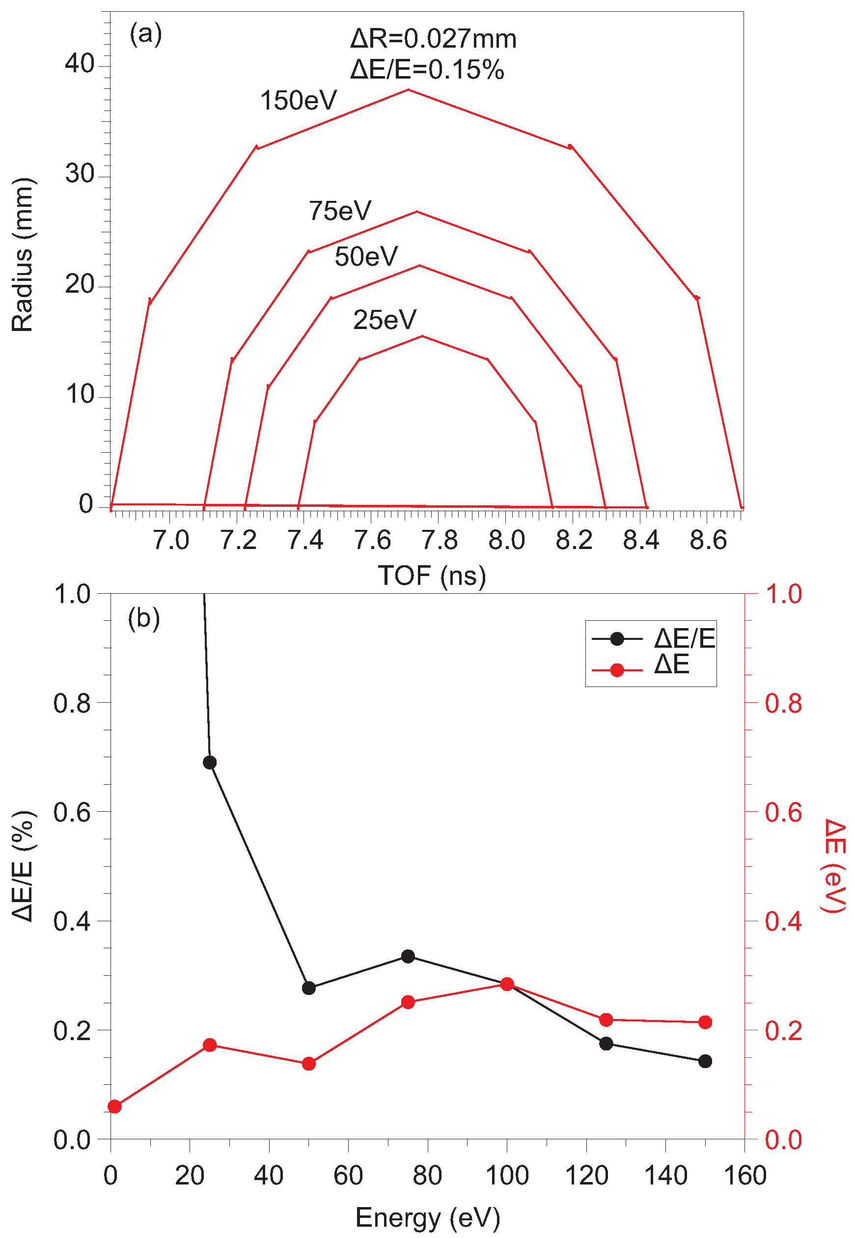
Figure 5a summarizes the simulation from Figure 4. The radius is plotted as a function of TOF for electrons with different kinetic energies. To obtain the simulated relative resolution, we calculated the average radius R and the maximum radius difference Δ R of the nine particles on the detector’s surface at an emittance angle of 90°. Then, the relative energy resolution is calculated as Δ E / E 2 Δ R / R . Figure 5b demonstrates the relative energy resolution at electron energies ranging from 0 to 150 eV in high-resolution momentum mapping mode. All the electrons at different kinetic energies and emission angles are nicely focused. Δ E depends weakly on the electron energy. The best relative energy resolution of 0.15% is predicted at 150 eV, which is the highest kinetic energy.

4. Experiment

We test the VMI spectrometer with above-threshold ionization (ATI) of argon (Ar). The supersonic Ar gas beam is ionized with a linearly polarized, 35 fs, 800 nm, 1 kHz Ti:Sapphire laser. The laser is focused to a peak intensity of 1.4 × 10¹⁴ W/cm2 through an optical lens with a focal length of 400 mm.
The supersonic jet, the reaction center of the VMI lens, and the laser focus may be misaligned from each other. This misalignment needs to be corrected at the beginning of the experiment. First, we put the laser focus on the reaction center of the VMI lens. The position of the laser focus and that of the reaction center of VMI lens are determined by checking the parent ion images of the residual gas in the uniform field mode and the focusing mode, respectively. Here, the residual gas molecules are preferred because they move isotropically. If the laser focus is misaligned from the reaction center, the center of the ion image will shift by switching the VMI lens between the uniform field mode and the focusing mode. Because the supersonic molecular beam possesses a specific mean velocity, it is not a suitable target for this alignment. By moving either the optical lens or the whole spectrometer, the distance between the laser focus and the reaction center can be reduced to below 0.5 mm, and then we believe the alignment quality is acceptable. Finally, by monitoring the ion counts, we switch on the supersonic molecular beam and move it to reach the maximum overlap with the laser focus. In the end, the laser and supersonic molecular beam intersect at the reaction center of the VMI spectrometer.
In order to further improve the resolution during the experiment, we set the exposure time of a single image to 50 ms, which can avoid the severe overlapping of fluorescence spots on the P46 screen. We enhance the contrast of each image using morphology [27]. Each energy spectrum generally needs to accumulate 20,000 images.

4.1. Spatial Mapping Mode

It is necessary to find the overlap between two laser focuses in a pump-probe experiment. This procedure could be pretty tedious if we do it in a vacuum chamber. Previously, the preliminary spatial overlap was found by either the optical mapping method [28] or the spatial mapping mode of VMI [19]. Here, we try to add magnification in the spatial mapping mode.
We capture spatial mode ion images, as shown in Figure 6. The absolute size is determined with reference to the 80 mm diameter of the phosphor screen. As indicated by the inserted diagram in Figure 6a, the supersonic molecular beam propagates up while the laser propagates to the right side. Through the adiabatic expansion, the supersonic molecular beam is cooled down to about 10 K with a mean speed higher than the room-temperature thermo-speed. In comparison, the residual gas is at room temperature. The laser is focused with a Rayleigh length of 4 mm and a beam waist of 68 μm. The diameter of the Ar jet is 1.2 mm. Upon interaction between the laser and Ar jet, the produced Ar+ ions are characterized by narrow velocity distribution and compact shape in the acquired image, shifting from a more dispersed image from the residual gas. So, the spot or narrower stripe with higher intensity in each subplot is attributed to Ar+, while the weaker and broader stripe is attributed to the ions from residual gas. It should be noted that since the ions from residual gas move isotropically, their image represents the reaction center better than the ion image from the jet does.
Figure 6a–e show the ion images with the simulated magnification factors: 1.0, 2.2, 2.8, 5.9 and 7.6, respectively. The actual magnification factors in the measurement are 1.0, 1.5, 1.8, 5.2 and 6.4, respectively. The jet image shifts more upward as the magnification factor increases. In the voltage setting of the higher magnification factor, the ions are retarded more, which leads to a longer ion time of flight and a larger jet image offset.
Spatial mapping mode is helpful for preliminarily overlapping two laser pulses in the Z-X plane in a pump-probe experiment. We compare the performance of spatial imaging of different spectrometers in Table 2. The best performance was achieved by Tsatrafyllis [21] using an ion microscope. Although we did not provide a high magnification factor, the magnified images help us to find good alignment. By monitoring the shift of ion image when switching the VMI lens between the spatial mapping mode and focusing mode, the alignment of the laser focus can be improved further to below 0.2 mm.
In Figure 6, the observed grids are from the metal mesh on the ninth electrode, where the microlens effect from the mesh cell can distort the ion images. This distortion is more severe at a larger magnification factor, which leads to a clearer grid pattern. Although Figure 6e is acquired at the simulated magnification factor of 7.6, the experimental magnification factor is 6.4. We speculate this is also due to the microlens effect beyond our simulation.

4.2. High-Resolution Momentum Mapping Mode

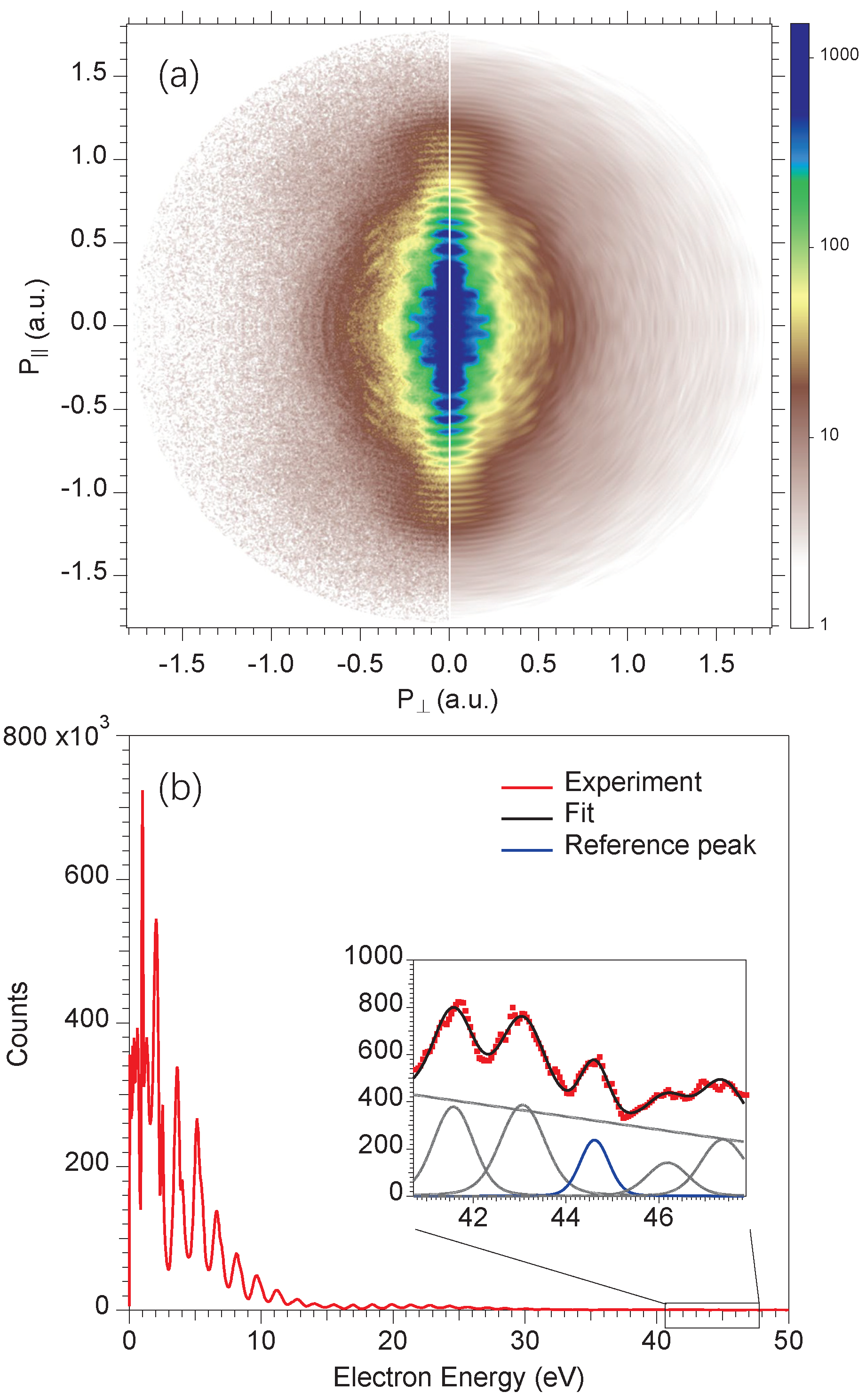
To evaluate the performance of the high-resolution momentum mapping mode of the VMI spectrometer, we measured the ATI image on Ar [29]. By scaling proportionally the VMI lens setting, the photoelectrons with an energy of up to 50 eV were covered. The measured 2D momentum spectrum is shown on the left side of Figure 7a and the reconstructed 2D-momentum distribution using polar-onion-peeling (POP) inversion [30,31] on the right side, respectively. The POP method was chosen here because it is very robust against low statistics and does not accumulate noise on the axis of the spectrum. Then, in order to show a high-energy structure, the electron energy spectrum was obtained by angular integrating the reconstructed image between the 0° and 12° with respect to the polarization axis and shown in Figure 7b.
To obtain the instrument’s resolution, we fit ATI peaks between 40.7 and 47.9 eV with Gaussian functions, as depicted by the black line in the inset of Figure 7b. As shown by Nandor et al. [32], the width of peaks at the plateau region may change. So, the fitting parameters are the peak width and height. A narrow ATI peak near 44.6 eV is chosen, and its full width half maximum (FWHM) is determined as 0.66 eV in the least square fitting. This width is contributed by the intrinsic width of the ATI peak and the instrument resolution. According to theoretical calculations [32], the intrinsic width of this ATI peak is about 0.3 eV. So, the energy resolution of the spectrometer is estimated as ( 0 . 66 2 0 . 3 2 ) = 0.59 eV, corresponding to 1.3% at 44.6 eV electron kinetic energy.
In Table 3, we have listed the performance of several VMI spectrometers designed for low, middle, and high kinetic energy, respectively. The results indicate that our VMI spectrometer works excellently in measuring both high-energy and middle-energy electrons.
There are several mechanisms that can deteriorate the energy resolution. Electric field distortions near the wire mesh can change the direction of passing charged particle [26]. The velocity change Δ v x in the x direction reaches a maximum at the wire, which is estimated as
Δ v x = q Δ E d 4 m v y .
Here, Δ E is the electric field difference between the two sides of the mesh, d is the mesh cell size, and v y is the particle velocity in the y direction. In the spatial mapping mode with the magnification factor of 6.4, Δ v x is estimated as 4.1 × 10 5 mm/ns. After the remaining time of flight of 5000 ns, the image distortion is about 0.2 mm. In the momentum mapping mode, Δ v x is estimated as 0.005 mm/ns. After the remaining time of flight of 10 ns, the image distortion is about 0.05 mm, which corresponds to a relative energy resolution of 0.33%. The estimated image distortions agree reasonably with the observed images in Figure 6 and Figure 7. In the original VMI paper by Eppink [2] that showed the microlens effect, two homogenous electric field regions are separated by a mesh. So, there is no focusing and the measured ion image is by far much worse than the one measured in VMI mode. After that, a mesh is often ascribed to be the principal killer of the resolution. However, the comparison was made between the ion image measured with the fine mesh grid with homogenous fields and that with imaging focusing lens. The destruction power of the mesh on the resolution may be overestimated.
Another factor that influence the resolution is the magnetic field, which is very difficult to estimate. The residual magnetic field strength in the main chamber was measured using a magnetometer. It varies from 6 mGs at the interaction region where the electron kinetic energy is several tens of eV to 50 mGs near the detector where the electron kinetic energy is about 800 eV. The distribution of the magnetic field is irregular due to the openings on the u-metal shield. So, we empirically simplify the current situation as a 300 eV electron flying for 140 mm in an 8 mGs magnetic field. As a result, the distortion is about 0.13 mm, corresponding to a relative energy resolution of 0.87%. If the electron kinetic energy is increased by a factor of 10, the magnetic distortion will be decreased by a factor of 10 .
With simulated relative resolution and the distortions by the mesh and the residual magnetic field into account, the total relative energy resolution is estimated as 0.94%, which reasonably agrees with the measurement. It is always striking to observe the shadow of the mesh on the measured images, while the effect from the residual magnetic field is not readily visible. Here, we believe that, in order to further improve the energy resolution of our spectrometer, the first priority is to reduce the residual magnetic field.

5. Summary

In this paper, we present a thorough demonstration of the performance of the velocity map imaging (VMI) spectrometer under different operation modes. We have confirmed that the spatial mapping mode of the VMI spectrometer can magnify the image of ions. The spatial mode with a larger magnification factor can help us to put the laser focus closer to the spectrometer axis. At the free electron laser facility, it will facillitate finding the spatial overlap between the fs laser pulse and free electron laser pulse. At 44.6 eV electron kinetic energy, we can achieve a relative resolution of 1.3%. Monochromatic X-ray radiation from synchrotron radiation would be necessary for a more quantitative estimation of the energy resolution.
Streaking [38] or RABBIT [39] methods prevail in attosecond experiments. The experiments were mainly conducted using an electron time-of-flight spectrometer due to the required resolution of 1% or better. In comparison, the use of VMI in this research is less active [40]. We expect to explore the angular dependence in the attosecond experiment by a further improved VMI spectrometer in the future.

Author Contributions

Conceptualization: X.L.; Data curation: Y.F., B.D., R.W., X.J., K.W., J.L. and J.H.; Investigation: Y.F., B.D., R.W., X.J., K.W., J.L. and J.H.; Funding acquisition: X.L.; Project administration: X.J. and K.W.; Supervision, X.L.; Writing, original draft: Y.F., B.D. and X.L.; Writing, review and editing: Y.F., B.D., R.W., X.J., K.W., J.L. and X.L. All authors have read and agreed to the published version of the manuscript.

Funding

This research was funded by the Double First-Class Initiative Fund of ShanghaiTech University and the National Natural Science Foundation of China (Grant No. 11574020).

Institutional Review Board Statement

Not applicable.

Informed Consent Statement

Not applicable.

Data Availability Statement

The data presented in this study are available on request from the corresponding author.

Conflicts of Interest

The authors declare no conflicts of interest.

References

  1. Chandler, D.W.; Houston, P.L. Two-dimensional imaging of state-selected photodissociation products detected by multiphoton ionization. J. Chem. Phys. 1987, 87, 1445–1447. [Google Scholar] [CrossRef]
  2. Eppink, A.T.J.B.; Parker, D.H. Velocity map imaging of ions and electrons using electrostatic lenses: Application in photoelectron and photofragment ion imaging of molecular oxygen. Rev. Sci. Instrum. 1997, 68, 3477–3484. [Google Scholar] [CrossRef]
  3. Garcia, G.A.; Nahon, L.; Harding, C.J.; Mikajlo, E.A.; Powis, I. A refocusing modified velocity map imaging electron/ion spectrometer adapted to synchrotron radiation studies. Rev. Sci. Instrum. 2005, 76, 053302. [Google Scholar] [CrossRef]
  4. Garcia, G.A.; Soldi-Lose, H.; Nahon, L. A versatile electron-ion coincidence spectrometer for photoelectron momentum imaging and threshold spectroscopy on mass selected ions using synchrotron radiation. Rev. Sci. Instrum. 2009, 80, 023102. [Google Scholar] [CrossRef]
  5. O’Keeffe, P.; Bolognesi, P.; Coreno, M.; Moise, A.; Richter, R.; Cautero, G.; Stebel, L.; Sergo, R.; Pravica, L.; Ovcharenko, Y.; et al. A photoelectron velocity map imaging spectrometer for experiments combining synchrotron and laser radiations. Rev. Sci. Instrum. 2011, 82, 033109. [Google Scholar] [CrossRef]
  6. Bodi, A.; Hemberger, P.; Gerber, T.; Sztáray, B. A new double imaging velocity focusing coincidence experiment: i2PEPICO. Rev. Sci. Instrum. 2012, 83, 083105. [Google Scholar] [CrossRef]
  7. Sztáray, B.; Voronova, K.; Torma, K.G.; Covert, K.J.; Bodi, A.; Hemberger, P.; Gerber, T.; Osborn, D.L. CRF-PEPICO: Double velocity map imaging photoelectron photoion coincidence spectroscopy for reaction kinetics studies. J. Chem. Phys. 2017, 147, 013944. [Google Scholar] [CrossRef] [PubMed]
  8. Rading, L.; Lahl, J.; Maclot, S.; Campi, F.; Coudert-Alteirac, H.; Oostenrijk, B.; Peschel, J.; Wikmark, H.; Rudawski, P.; Gisselbrecht, M.; et al. A Versatile Velocity Map Ion-Electron Covariance Imaging Spectrometer for High-Intensity XUV Experiments. Appl. Sci. 2018, 8, 998. [Google Scholar] [CrossRef]
  9. Cavanagh, S.J.; Gibson, S.T.; Gale, M.N.; Dedman, C.J.; Roberts, E.H.; Lewis, B.R. High-resolution velocity-map-imaging photoelectron spectroscopy of the O photodetachment fine-structure transitions. Phys. Rev. A 2007, 76, 052708. [Google Scholar] [CrossRef]
  10. Kling, N.G.; Paul, D.; Gura, A.; Laurent, G.; De, S.; Li, H.; Wang, Z.; Ahn, B.; Kim, C.H.; Kim, T.K.; et al. Thick-lens velocity-map imaging spectrometer with high resolution for high-energy charged particles. J. Instrum. 2014, 9, P05005. [Google Scholar] [CrossRef]
  11. Ding, B.; Xu, W.; Wu, R.; Feng, Y.; Tian, L.; Li, X.; Huang, J.; Liu, Z.; Liu, X. A Composite Velocity Map Imaging Spectrometer for Ions and 1 keV Electrons at the Shanghai Soft X-ray Free-Electron Laser. Appl. Sci. 2021, 11, 10272. [Google Scholar] [CrossRef]
  12. Glownia, J.M.; Cryan, J.; Andreasson, J.; Belkacem, A.; Berrah, N.; Blaga, C.I.; Bostedt, C.; Bozek, J.; DiMauro, L.F.; Fang, L.; et al. Time-resolved pump-probe experiments at the LCLS. Opt. Express 2010, 18, 17620–17630. [Google Scholar] [CrossRef] [PubMed]
  13. Krausz, F.; Ivanov, M. Attosecond physics. Rev. Mod. Phys. 2009, 81, 163–234. [Google Scholar] [CrossRef]
  14. Lépine, F.; Ivanov, M.Y.; Vrakking, M.J.J. Attosecond molecular dynamics: Fact or fiction? Nat. Photonics 2014, 8, 195–204. [Google Scholar] [CrossRef]
  15. Erk, B.; Boll, R.; Trippel, S.; Anielski, D.; Foucar, L.; Rudek, B.; Epp, S.W.; Coffee, R.; Carron, S.; Schorb, S.; et al. Imaging charge transfer in iodomethane upon x-ray photoabsorption. Science 2014, 345, 288–291. [Google Scholar] [CrossRef]
  16. Allum, F.; Anders, N.; Brouard, M.; Bucksbaum, P.; Burt, M.; Downes-Ward, B.; Grundmann, S.; Harries, J.; Ishimura, Y.; Iwayama, H.; et al. Multi-channel photodissociation and XUV-induced charge transfer dynamics in strong-field-ionized methyl iodide studied with time-resolved recoil-frame covariance imaging. Faraday Discuss. 2021, 228, 571–596. [Google Scholar] [CrossRef]
  17. Corrales, M.E.; González-Vázquez, J.; Balerdi, G.; Solá, I.R.; de Nalda, R.; Bañares, L. Control of ultrafast molecular photodissociation by laser-field-induced potentials. Nat. Chem. 2014, 6, 785–790. [Google Scholar] [CrossRef]
  18. Corrales, M.E.; de Nalda, R.; Bañares, L. Strong laser field control of fragment spatial distributions from a photodissociation reaction. Nat. Commun. 2017, 8, 1345. [Google Scholar] [CrossRef]
  19. Johnsson, P.; Rouzée, A.; Siu, W.; Huismans, Y.; Lépine, F.; Marchenko, T.; Düsterer, S.; Tavella, F.; Stojanovic, N.; Redlin, H.; et al. Characterization of a two-color pump–probe setup at FLASH using a velocity map imaging spectrometer. Opt. Lett. 2010, 35, 4163–4165. [Google Scholar] [CrossRef]
  20. Benis, E.P.; Xia, J.F.; Tong, X.M.; Faheem, M.; Zamkov, M.; Shan, B.; Richard, P.; Chang, Z. Ionization suppression of Cl2 molecules in intense laser fields. Phys. Rev. A 2004, 70, 025401. [Google Scholar] [CrossRef]
  21. Tsatrafyllis, N.; Bergues, B.; Schröder, H.; Veisz, L.; Skantzakis, E.; Gray, D.; Bodi, B.; Kuhn, S.; Tsakiris, G.D.; Charalambidis, D.; et al. The ion microscope as a tool for quantitative measurements in the extreme ultraviolet. Sci. Rep. 2016, 6, 21556. [Google Scholar] [CrossRef]
  22. Stei, M.; von Vangerow, J.; Otto, R.; Kelkar, A.H.; Carrascosa, E.; Best, T.; Wester, R. High resolution spatial map imaging of a gaseous target. J. Chem. Phys. 2013, 138, 214201. [Google Scholar] [CrossRef]
  23. Bastian, B.; Asmussen, J.D.; Ben Ltaief, L.; Czasch, A.; Jones, N.C.; Hoffmann, S.V.; Pedersen, H.B.; Mudrich, M. A new endstation for extreme-ultraviolet spectroscopy of free clusters and nanodroplets. Rev. Sci. Instrum. 2022, 93, 075110. [Google Scholar] [CrossRef]
  24. Irimia, D.; Dobrikov, D.; Kortekaas, R.; Voet, H.; van den Ende, D.A.; Groen, W.A.; Janssen, M.H.M. A short pulse (7 μs FWHM) and high repetition rate (dc-5kHz) cantilever piezovalve for pulsed atomic and molecular beams. Rev. Sci. Instrum. 2009, 80, 113303. [Google Scholar] [CrossRef] [PubMed]
  25. Jones, W.; Clark, J. Simion Ion Optics Simulation. Ver 8.2. Available online: https://simion.com/ (accessed on 3 February 2024).
  26. Bergmann, T.; Martin, T.P.; Schaber, H. High-resolution time-of-flight mass spectrometers: Part I. Effects of field distortions in the vicinity of wire meshes. Rev. Sci. Instrum. 1989, 60, 347–349. [Google Scholar] [CrossRef]
  27. Peters, R.A. A new algorithm for image noise reduction using mathematical morphology. IEEE Trans. Image Process. 1995, 4, 554–568. [Google Scholar] [CrossRef] [PubMed]
  28. Radcliffe, P.; Düsterer, S.; Azima, A.; Li, W.B.; Plönjes, E.; Redlin, H.; Feldhaus, J.; Nicolosi, P.; Poletto, L.; Dardis, J.; et al. An experiment for two-color photoionization using high intensity extreme-UV free electron and near-IR laser pulses. Phys. Res. Sect. A Accel. Spectrometers Detect. Assoc. Equip. 2007, 583, 516–525. [Google Scholar] [CrossRef]
  29. Werby, N.; Natan, A.; Forbes, R.; Bucksbaum, P.H. Disentangling the subcycle electron momentum spectrum in strong-field ionization. Phys. Rev. Res. 2021, 3, 023065. [Google Scholar] [CrossRef]
  30. Zipp, L.J.; Natan, A.; Bucksbaum, P.H. Probing electron delays in above-threshold ionization. Optica 2014, 1, 361–364. [Google Scholar] [CrossRef]
  31. Roberts, G.M.; Nixon, J.L.; Lecointre, J.; Wrede, E.; Verlet, J.R.R. Toward real-time charged-particle image reconstruction using polar onion-peeling. Rev. Sci. Instrum. 2009, 80, 053104. [Google Scholar] [CrossRef]
  32. Nandor, M.J.; Walker, M.A.; Woerkom, L.D.V. Angular distributions of high-intensity ATI and the onset of the plateau. J. Phys. B At. Mol. Opt. Phys. 1998, 31, 4617. [Google Scholar] [CrossRef]
  33. León, I.; Yang, Z.; Liu, H.T.; Wang, L.S. The design and construction of a high-resolution velocity-map imaging apparatus for photoelectron spectroscopy studies of size-selected clusters. Rev. Sci. Instrum. 2014, 85, 083106. [Google Scholar] [CrossRef]
  34. Schomas, D.; Rendler, N.; Krull, J.; Richter, R.; Mudrich, M. A compact design for velocity-map imaging of energetic electrons and ions. J. Chem. Phys. 2017, 147, 013942. [Google Scholar] [CrossRef]
  35. Ghafur, O.; Siu, W.; Johnsson, P.; Kling, M.F.; Drescher, M.; Vrakking, M.J.J. A velocity map imaging detector with an integrated gas injection system. Rev. Sci. Instrum. 2009, 80, 033110. [Google Scholar] [CrossRef] [PubMed]
  36. Ablikim, U.; Bomme, C.; Osipov, T.; Xiong, H.; Obaid, R.; Bilodeau, R.C.; Kling, N.G.; Dumitriu, I.; Augustin, S.; Pathak, S.; et al. A coincidence velocity map imaging spectrometer for ions and high-energy electrons to study inner-shell photoionization of gas-phase molecules. Rev. Sci. Instrum. 2019, 90, 055103. [Google Scholar] [CrossRef]
  37. Skruszewicz, S.; Passig, J.; Przystawik, A.; Truong, N.X.; Köther, M.; Tiggesbäumker, J.; Meiwes-Broer, K.H. A new design for imaging of fast energetic electrons. Int. J. Mass Spectrom. 2014, 365–366, 338–342. [Google Scholar] [CrossRef]
  38. Goulielmakis, E.; Uiberacker, M.; Kienberger, R.; Baltuska, A.; Yakovlev, V.; Scrinzi, A.; Westerwalbesloh, T.; Kleineberg, U.; Heinzmann, U.; Drescher, M.; et al. Direct Measurement of Light Waves. Science 2004, 305, 1267–1269. [Google Scholar] [CrossRef] [PubMed]
  39. Isinger, M.; Squibb, R.J.; Busto, D.; Zhong, S.; Harth, A.; Kroon, D.; Nandi, S.; Arnold, C.L.; Miranda, M.; Dahlström, J.M.; et al. Photoionization in the time and frequency domain. Science 2017, 358, 893–896. [Google Scholar] [CrossRef]
  40. Vrakking, M.J.J. Attosecond imaging. Phys. Chem. Chem. Phys. 2014, 16, 2775–2789. [Google Scholar] [CrossRef] [PubMed]
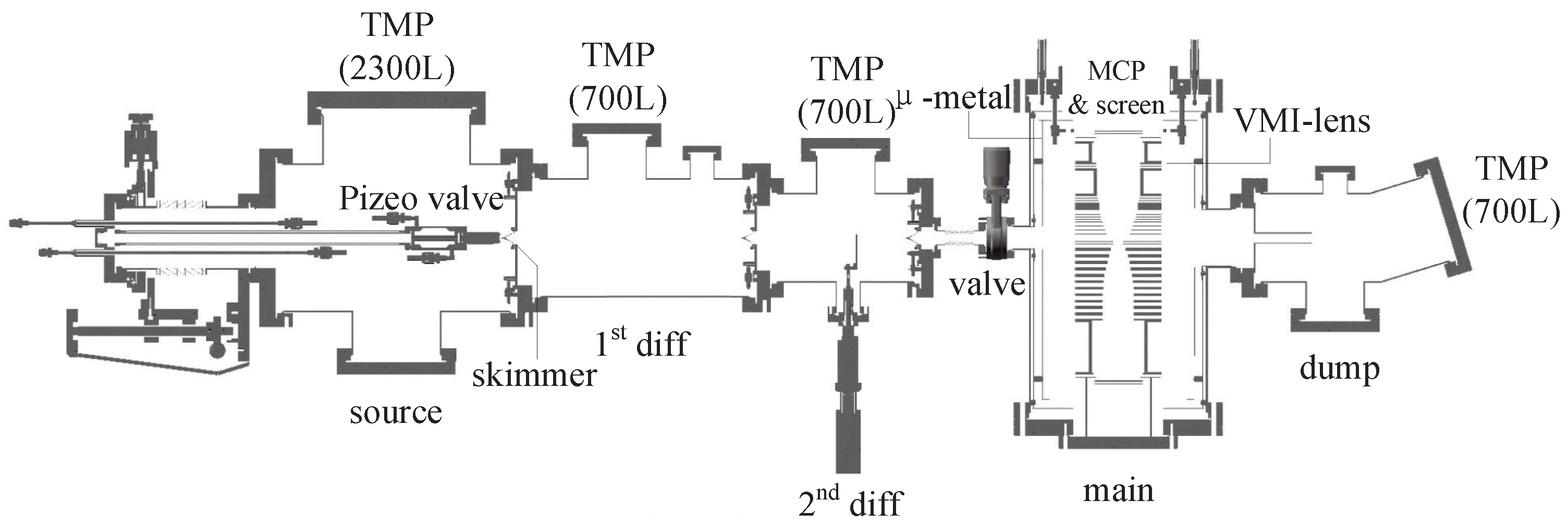
Figure 1. The overall structure of the velocity map imaging spectrometer. The supersonic molecular beam is generated in the source chamber, passes the first and second differential chambers, interacts with the photon beam in the main chamber, and finally is pumped out in the dump chamber. The generated electrons and ions are guided to the detectors on each end by the VMI lens in the main chamber.
Applsci 14 02190 g001
Figure 2. Simulation of the spatial mapping mode with a scale factor of 7.6. The source region is defined as 1 × 3 mm2. The black lines represent the trajectories of the ion and the red lines represent the equipotential curves of the electric field.
Applsci 14 02190 g002
Figure 3. The simulated linearity of the spatial mapping mode.
Applsci 14 02190 g003
Figure 4. Simulation of the high-resolution momentum mapping mode. The source region is defined as 3 × 3 points from a rectangular region of dimensions 1 × 3 mm2. The kinetic energy of electrons is 150 eV. The colors represent the different emission angles of the electrons. The emission angle ranges from 0 to 180° with an interval of 30°.
Applsci 14 02190 g004
Figure 5. Summary of the simulation results in the high-resolution momentum mapping mode. using SIMION 8.2 from Scientific Instrument Services, Palmer, MA, USA (a) Electron kinetic energies from outside to inside are 150, 75, 50, and 25 eV, respectively. (b) Simulated electron kinetic energy resolution Δ E/E and Δ E as a function of electron kinetic energy. The resolution of the high-resolution momentum mapping mode is around 0.22 eV (red line), and we can reach a relative resolution of 0.15% (black line) at 150 eV.
Applsci 14 02190 g005
Figure 6. Spatial mode ion images in spatial mapping mode with different magnification factors. The intensities are given in log scale to make the contribution from the residual gas visible. The simulated magnification factors are (a) 1.0, (b) 2.2, (c) 2.8, (d) 6.0 and (e) 7.6, respectively, while the measured magnification factors are (a) 1.0, (b) 1.5, (c) 1.8, (d) 5.2 and (e) 6.4, respectively.
Applsci 14 02190 g006
Figure 7. ATI measurement on Ar. (a) Raw 2D-momentum distribution of electrons is shown on the left side, and the 2D-momentum distribution reconstructed by the polar onion peeling method is shown on the right side. The intensity in the interaction region is 1.4 × 10¹⁴ W/cm2. (b) Photoelectron spectra of Ar ionized by 800 nm linearly polarized laser pulses. The photoelectron kinetic energy spectrum was obtained by integration of the momentum distribution within 0° to 12° with resect to the laser polarization axis. The red squares represent the photoelectron spectrum, and the peak at 44.6 eV is selected to represent the resolution, as shown by the blue line in the enlarged inserted picture.
Applsci 14 02190 g007
Table 1. The geometric configurations of the electron arm and the voltages (V) on the electrodes in spatial mapping mode and high-resolution momentum mapping mode. The voltages in the momentum mapping mode is scaled to the electron kinetic energy.
Geometry (mm)Voltages (V)
DISTTHID Ion Electron
×1.0×2.2×2.8×5.9×7.6150 eV
1−95320.000.000.000.000.000.00
29139−145.00−557.84−609.25−924.02−1026.46710.86
316145−215.00−630.63−655.37−806.86−856.111167.22
423150−285.00−713.68−717.52−741.05−748.711690.25
527154−325.00−725.84−725.75−725.23−725.051393.81
631158−365.00−856.60−856.23−853.94−853.191749.89
735160−405.00−1010.42−1010.02−1007.51−1006.702177.87
839162−445.00−1102.81−1102.72−1102.10−1101.912725.96
943164−485.00−1032.90−1147.87−1147.70−1147.653096.81
10471366−620.00−1147.79−1163.66−948.53−878.583583.11
1163168−685.00−1393.94−1394.95−1401.18−1403.203309.72
1267171−725.00−1499.74−1500.63−1506.08−1507.852819.75
13714874−1000.00−1610.91−1614.94−1639.63−1647.652282.31
14122175−1275.00−1636.33−1636.31−1636.18−1636.141654.07
151264176−1525.00−1715.00−1710.33−1692.93−1687.272000.00
DIST = the distance of the electrodes to the interaction region, TH = thicknesses, ID = inner diameter.
Table 2. List of the performance of spatial imaging measured in spectrometers.
AuthorMagnification FactorType
Tsatrafyllis [21]80.0Ion microscope
Stei [22]−14.6Ion microscope
Benis [20]6.8Ion microscope
Johnsson [19]−6.0Two-mode VMI
This work1.0, 1.5, 1.8, 5.2, 6.4Two-mode VMI
Table 3. List of the performance of the measured relative energy resolution in VMI spectrometers.
AuthorKE [eV]ΔE/EMeshYear
Cavanagh [9]0.870.38%NO2007
León [33]30.53%NO2014
Kling [10]601.5%NO2014
Schomas [34]653.0%NO2017
Ghafur [35]1001.8%NO2009
Ablikim [36]1003.8%NO2019
Skruszweicz [37]3004.0%NO2014
Ding [11]5001.5%YES2021
This work44.61.3%YES2023
Disclaimer/Publisher’s Note: The statements, opinions and data contained in all publications are solely those of the individual author(s) and contributor(s) and not of MDPI and/or the editor(s). MDPI and/or the editor(s) disclaim responsibility for any injury to people or property resulting from any ideas, methods, instructions or products referred to in the content.