1. Introduction
The rapid advancement of the global economy has led to a steep surge in humanity’s demand for energy. Simultaneously, the extensive use of fossil fuels has resulted in the generation and emission of significant quantities of greenhouse gases, exacerbating the increasingly severe issue of global climate change. The global climate change discourse has garnered worldwide attention. To address these challenges, governments worldwide have initiated measures towards energy transition for sustainable development, aiming to diminish reliance on petrochemical energy sources [
1]. They are pivoting towards the development and application of renewable energy [
2]. The trend toward sustainable energy development, aimed at reducing greenhouse gas emissions, has become imperative. Taiwan, too, is progressively promoting energy transition, with the development of renewable energy emerging as one of its future objectives.
Within Taiwan’s 2050 net-zero target, there are projections to elevate the proportion of renewable energy to 60% or 70% [
3]. Wind power and solar photovoltaics are envisioned as the primary power generation installations. However, both wind power and solar photovoltaics exhibit intermittent and challenging-to-predict generation characteristics [
4,
5]. With the integration of a substantial amount of renewable energy into the grid, its generation characteristics can impact grid operations, leading to congestion and posing a significant challenge to power system dispatch. The literature [
6,
7,
8,
9] indicates that the integration of large-scale renewable energy generation makes the system difficult to stabilize and control, significantly increasing the demand for system frequency regulation. If the instantaneous variation in renewable energy generation is excessive, it may cause a rapid increase or decrease in system frequency, severely affecting the power system’s supply security and reliability [
10,
11]. With the increasing penetration of renewable energy, nations aspire to mitigate the impacts arising from the large-scale integration of renewable energy into the grid. To achieve this, countries seek assistance from large-scale energy storage systems to stabilize power system operations [
12]. References [
13,
14] suggest that energy storage systems can alleviate the balance difficulties caused by renewable energy generation in power systems. The Taiwan Power Company (Taipower) has also implemented measures by introducing emerging technological resources and establishing a power trading platform. Auxiliary services and reserve capacity serve as driving factors for power trading, encompassing frequency regulation reserve, real-time reserve, and supplementary reserve services.
Reference [
15] proposes a method for evaluating the performance of energy storage systems and traditional generators in frequency regulation within a single-area power system. The case study results indicate that energy storage systems can reduce regulation requirements and are more effective in frequency regulation compared to traditional generators. In another study [
16], researchers primarily investigate the significant dynamic operational advantages of large battery energy storage facilities in the power utility sector, particularly in the realm of frequency regulation. The study examines the impact of a 30 MW battery on frequency regulation, emphasizing the importance of battery energy storage equipment in frequency regulation. Reference [
17] examines the technical application of flywheel energy storage systems in isolated power systems with high penetration of renewable energy. It discusses the advantages of using flywheel energy storage, different control schemes, and their impact on frequency regulation. In another study [
18], an approach named DaSOF is introduced, aimed at enhancing frequency response and regulation services in grids with high renewable energy. This method provides a unified frequency control framework for distributed and energy-constrained energy storage systems, complementing the frequency control of existing generators. Reference [
19] delves into the primary challenges of achieving 100% renewable energy penetration in low-inertia, isolated grids, including frequency control and stability. The study focuses on small island systems and proposes a solution using pumped hydro storage to enhance frequency regulation.
This paper is based on the E-dReg0.5 specification, an extension of the frequency regulation reserve auxiliary service dReg0.5. Taking into account the charging state of energy storage systems [
20,
21,
22], a sophisticated dynamic frequency reserve controller has been designed. Leveraging the rapid charging and discharging capabilities of energy storage systems [
23,
24], the controller manages the charge and discharge operations through controlled actions on the energy storage system within the power grid. This controller not only aids in maintaining the frequency drift caused by load fluctuations in the power system but also incorporates energy transfer functionality in addition to frequency regulation reserve. This ensures that the controller can operate with high performance quality, contributing to the stable and balanced operation of the power system. By considering the charging state of the energy storage system, this controller achieves controlled rapid charge and discharge, further ensuring stable performance quality.
The present dissertation comprises five chapters in total, structured as follows:
Section 2 elucidates the pertinent regulations concerning the auxiliary service products planned by the Taiwan Power Company, with a specific focus on elucidating and introducing E-dReg.
Section 3 introduces the hardware equipment and programming languages utilized in developing the enhanced dynamic frequency regulation controller, along with providing an exposition on the control strategies proposed for E-dReg in this paper.
Section 4 presents and discusses the results of the controller’s testing.
Section 5 summarizes the research findings of this dissertation. Finally, the references used are provided.
2. Introduction to Taipower Auxiliary Services
The Taipower power trading platform [
25] operates as a mechanism for power transactions, with a focus on auxiliary services [
26] and reserve capacity. Established for the auxiliary services market, the platform incorporates a greater number of rapidly responsive, flexible, and diverse distributed resources into the power system. Taipower’s auxiliary service products encompass a series of services aimed at ensuring the safe operation of the power system, restoring system security, and ensuring a stable power supply.
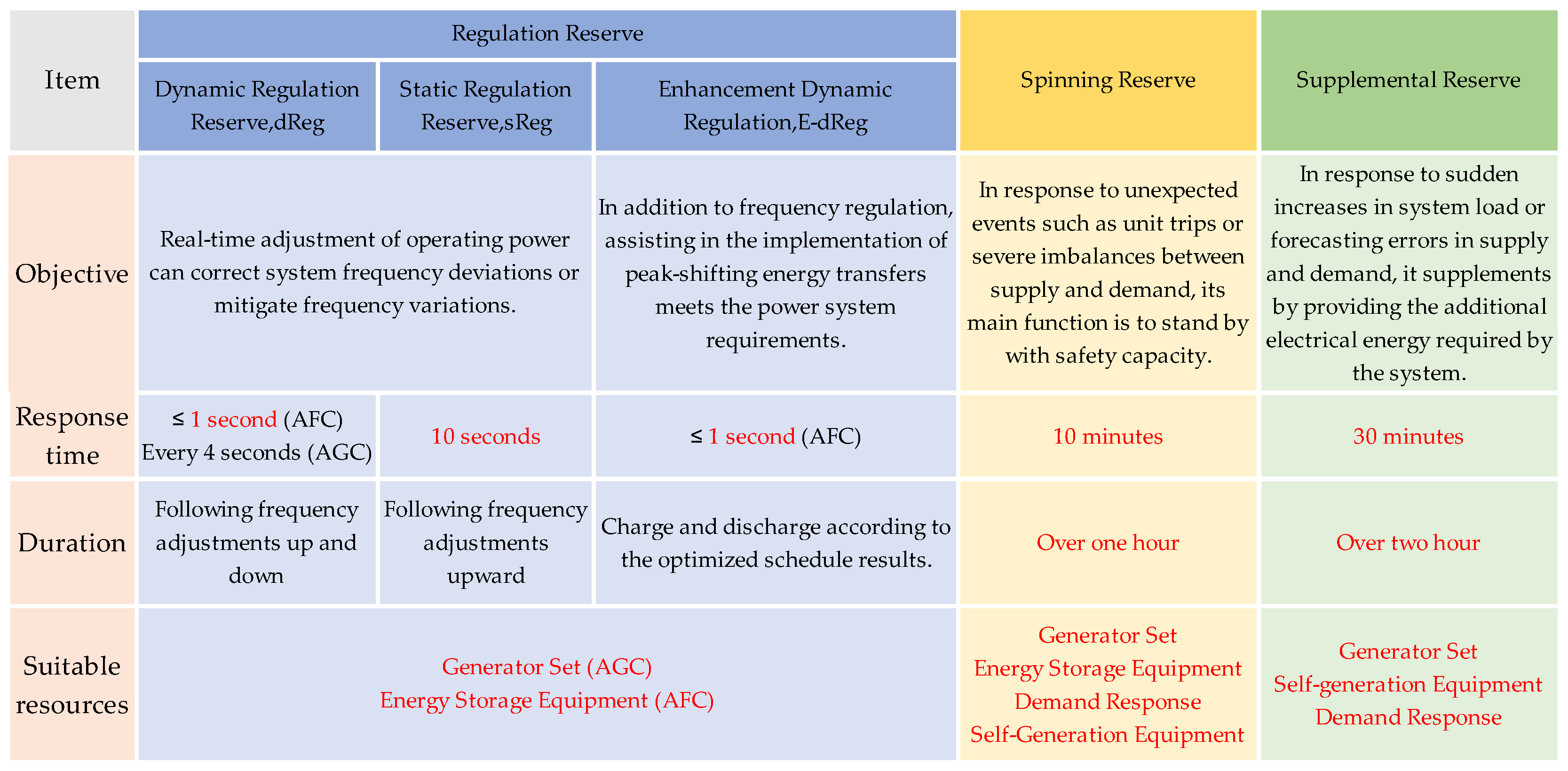
Figure 1 illustrates the current types of auxiliary services promoted and implemented by Taipower. Currently, there are three auxiliary service transaction projects in the market: regulation reserve, spinning reserve, and supplemental reserve.
Due to the variability in the power grid during the power generation process, significant fluctuations can lead to overall instability in grid frequency. Therefore, frequency regulation services are necessary to assist in stabilizing the grid frequency. Frequency regulation reserve services can be further divided into static regulation reserve (sReg) and dynamic regulation reserve (dReg). Within the dReg category, there are three technical specifications: dReg0.25, dReg0.5, and E-dReg. The technical specifications for E-dReg are introduced as follows.
Enhanced Dynamic Regulation Reserve (E-dReg)
E-dReg is a commodity traded on Taipower’s electricity trading platform, belonging to the category of frequency reserve capacity auxiliary services. It possesses dynamic frequency regulation and electricity transfer capabilities, aiding in enhancing the dispatch flexibility of the power system.
In typical circumstances, the primary operating range of dReg0.5 is usually less than ± 50%, while dReg0.25 is approximately ± 75%. Since the operating range of dReg usually does not reach 100%, as shown in
Figure 2, dReg0.25 can meet Taipower’s frequency regulation needs most of the time. Therefore, Taipower has introduced the enhanced dynamic regulation reserve (E-dReg) to optimize the usage efficiency of dReg0.5. E-dReg not only possesses the functionality of frequency regulation provided by dReg but also incorporates the peak-to-off-peak energy transfer feature, as shown in
Figure 3 and
Figure 4. E-dReg is envisioned to be the optimal operational tool for scheduling auxiliary services in completing the energy transition in the future. Compared to dReg, E-dReg not only assists in rapidly adjusting the power grid system frequency but also adds the functionality of peak-to-off-peak energy transfer. By storing excess electrical energy in energy storage systems and releasing it during peak demand moments, E-dReg aids in regulating peak and off-peak electricity demand effectively, enhancing the resilience of the grid and alleviating the pressure on Taipower’s supply during the nighttime second peak.
Table 1 is illustrated by a grid-connected energy storage resource with a capacity of 10 MW/25 MWh as an example.
Table 1 outlines the schematic operation of the enhanced dynamic regulation reserve (E-dReg) during actual operation. During the energy transfer scheduling period, the command for energy transfer must be executed simultaneously with the frequency regulation service. If the overall output capacity exceeds the contracted transaction capacity with Taipower, only the maximum transaction capacity will be output. In the event that the frequency surpasses the critical threshold of 60 Hz ± 0.5 Hz, the command for energy transfer must be temporarily suspended for 900 s. After the 900 s pause, the execution of the original energy command can resume.
In addition, the power trading platform has established a mechanism for emergency dispatch instructions to address unforeseen situations such as abnormal generator failures or sudden increases in system load that may occur on the scheduling day. The power dispatch unit will directly issue energy dispatch commands based on the needs of the power system through the telecommunication module. The telecommunication module sends real-time charging or discharging capacity commands every minute, and the execution of the dispatch command is completed within one minute of the command being issued. This mechanism ensures that the power system can promptly and effectively dispatch resources in special circumstances to ensure the stable operation of the power system.
3. Design of the Enhanced Dynamic Regulation Reserve Controller
3.1. Enhanced Dynamic Regulation Reserve System Architecture
The architecture of the enhanced dynamic regulation reserve system mainly consists of energy storage units and a monitoring and dispatch management system. It includes components such as the power grid (Grid), power conditioning system (PCS), battery energy storage system (BESS), energy management system (EMS), and controller. The schematic diagram of the system architecture is illustrated in
Figure 5. The power conditioning system and battery energy storage system form a bidirectional power system, while the controller establishes a communication link with the energy management system through Ethernet. The energy management system communicates with Taipower for data exchange, creating a comprehensive enhanced dynamic regulation reserve system.
This paper adopts Advantech Co., Ltd.’s (Taipei City, Taiwan) customized industrial PC (IPC) as the hardware equipment for developing a dynamic regulation modulation controller. In comparison to a personal computer (PC), industrial computers offer higher reliability, a longer lifespan, superior computing power, and capabilities such as dust resistance, waterproofing, and shock resistance. For the software aspect, the National Instruments (NI) LabVIEW programming language is employed for frequency control. LabVIEW, developed by National Instruments, is primarily used in engineering fields for testing, measurement, control, and automation. It provides an intuitive and user-friendly programming environment, allowing users to write complex programs in a graphical manner.
According to the full text of the power trading platform management regulations and operating procedures announced by Taipower on the power trading platform [
30], qualified traders participating in frequency regulation reserve capacity must independently set up system frequency detection equipment. Regarding the specifications for the frequency detection equipment, the minimum measurement accuracy for identifying changes in system frequency, i.e., the minimum resolution for system frequency, must be ≤0.01 Hz. Within the system frequency measurement range of 60.50 Hz to 59.50 Hz, the absolute value of the measured system frequency error should not exceed 0.01 Hz, ensuring that the measurement error of the system frequency is within 0.01 Hz. This thesis utilizes power sensing instrumentation developed and produced by ADTEK. To meet Taipower’s requirement for a frequency detection equipment reading of 10 frequency values per second, this paper selects the CPM-80 and CPM-72 multifunction power quality analyzers. The CPM-72 is used for reading other relevant power parameter measurement devices, while the CPM-80 serves as the frequency measurement equipment.
3.2. The Control Strategy of Enhanced Dynamic Regulation (E-dReg)
The control strategy proposed in this paper for E-dReg is designed and developed based on the foundation of a dynamic regulation reserve control strategy. E-dReg enhances the functionality of dynamic regulation reserve by incorporating energy transfer during peak and off-peak periods. The control strategy for enhanced dynamic regulation, as presented in this paper, operates within specified state-of-charge (SOC) conditions. It precisely controls the SOC of the energy storage system within the desired range while correctly executing frequency regulation functions. Simultaneously, during frequency regulation actions, it incorporates Taipower’s energy transfer schedules or commands. The designed control strategy not only maximizes the charge and discharge efficiency of the energy storage system’s limited battery capacity but also ensures the overall quality of frequency regulation and energy transfer execution.
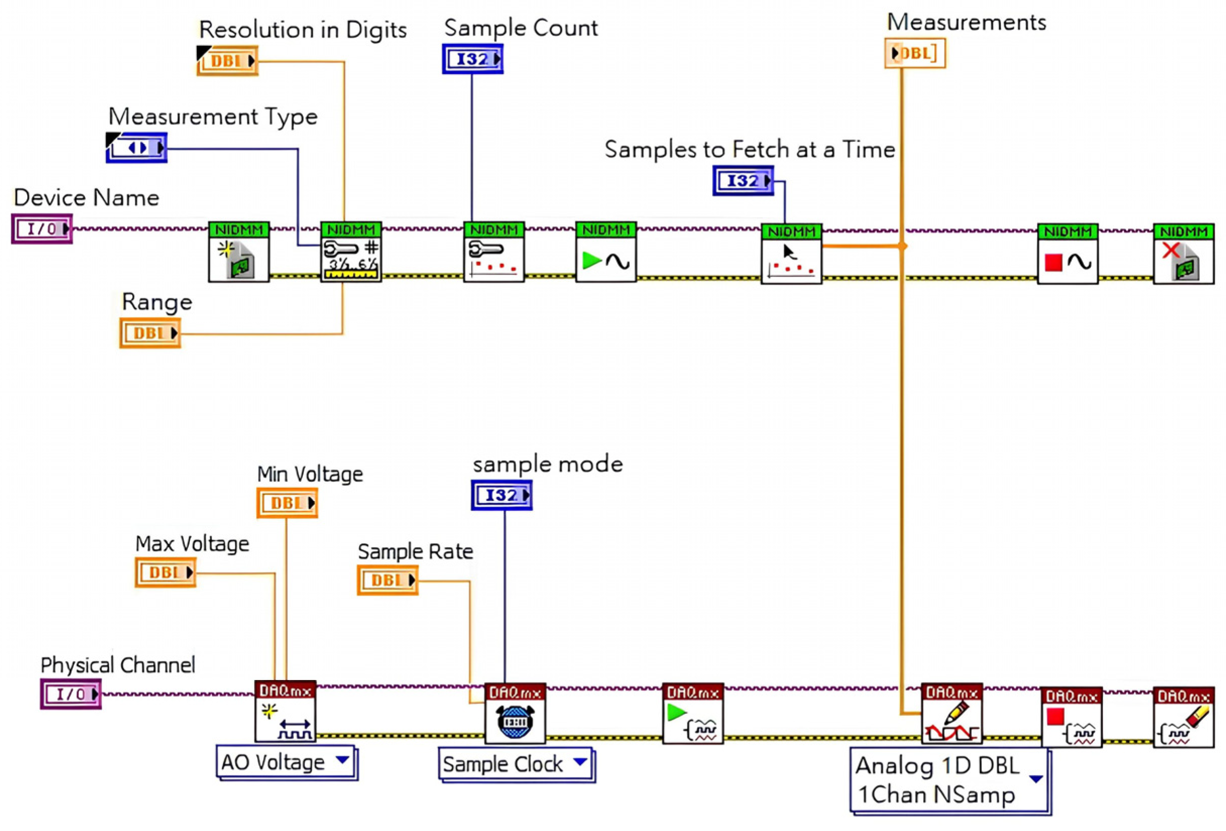
The control strategy designed in this paper utilizes LabVIEW as the programming language. Initially, this strategy employs a multifunctional power quality analyzer to measure the current frequency of the power system, and then the data are read into the LabVIEW program. The program will calculate the corresponding output power ratio based on the current SOC of the battery and the frequency status, in accordance with the control strategy. The schematic diagram of the control program is depicted in
Figure 6 and
Figure 7.
In this paper, simulations will be conducted using a 5 MW/12.5 MWh grid-connected energy storage capacity as an example. The designed control strategy for E-dReg will be tested to evaluate its effectiveness.
3.2.1. Control Flow Chart
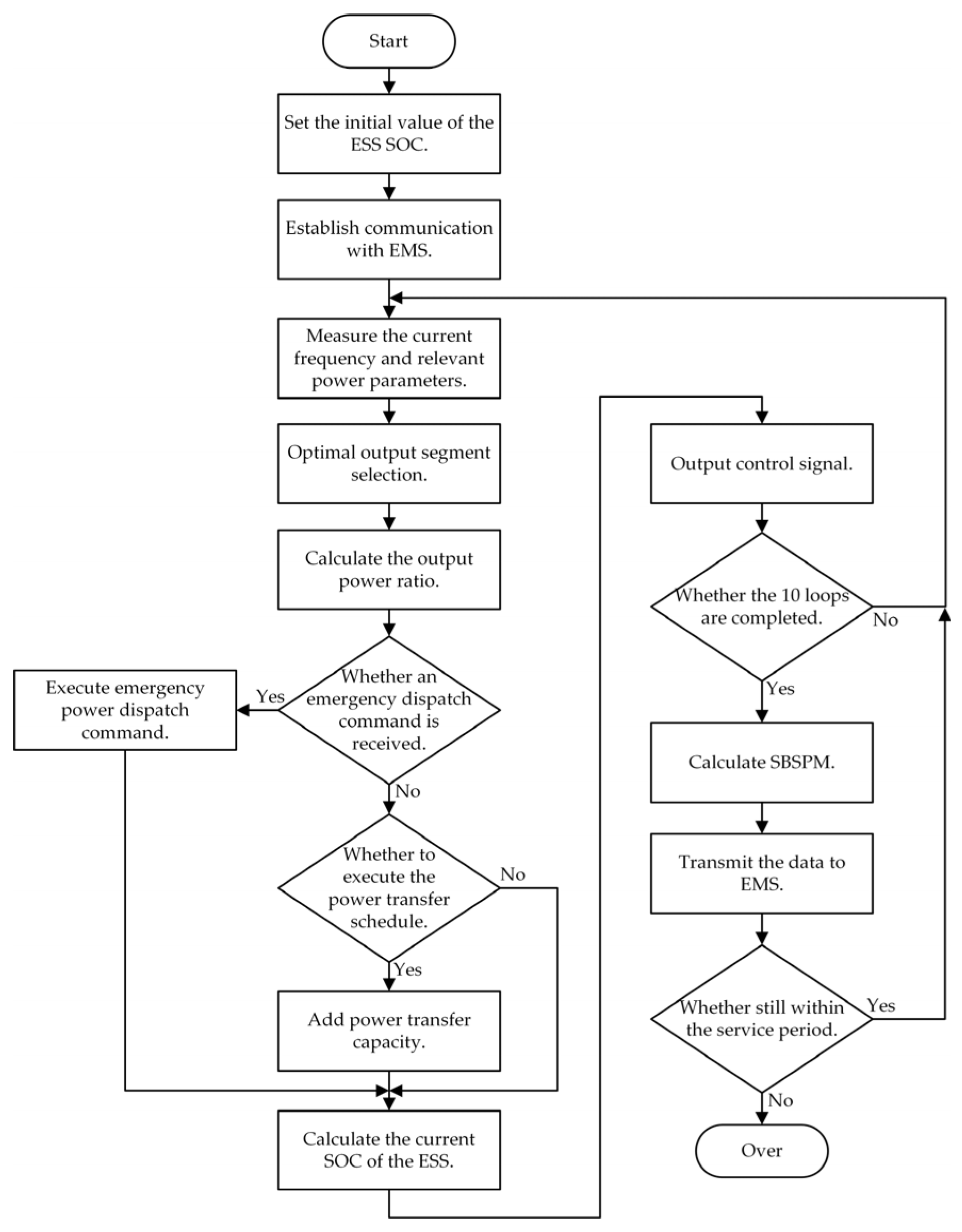
In the E-dReg control method proposed in this article, the program begins by assigning an initial SOC to the energy storage system and establishing communication with the EMS. A multifunctional electric meter measures the system’s current frequency and other necessary electrical parameters, which are then transmitted to the program. Based on this data, the program calculates the output power ratio for the current second and determines whether an energy transfer action is needed for the current period or if an emergency dispatch order from Taipower requires the execution of an energy transfer action. Control signals are then output through a data acquisition card (DAQ). After completing 10 loops, the electrical parameters required every 10 s are uploaded to Taipower by the EMS. The control flow chart is illustrated in
Figure 8.
3.2.2. State-of-Charge (SOC) Limitations of Battery Energy Storage System
To safeguard the battery energy storage system from situations where the SOC becomes excessively high or low due to prolonged charging or discharging, the proposed dynamic frequency regulation control strategy in this paper dynamically adjusts the output curve selection based on the current SOC of the energy storage system. This real-time scheduling helps prevent overcharging or over-discharging, thereby extending the lifespan of the battery energy storage system.
When the frequency of the power system is higher, the energy storage system must be charged to stabilize frequency (absorbing power from the power system), and the SOC may reach
. On the contrary, when the frequency of the power system is lower, the energy storage system must discharge (supplying power to the power system) to stabilize the frequency, and the SOC may reach
. In this paper, upper and lower limits have been imposed on the SOC to ensure that the charging and discharging actions of the energy storage system always operate within a safe range, as represented by Equation (1). Here,
denotes the output power,
represents the current SOC of the energy storage system,
denotes the upper limit set for the SOC, and
denotes the lower limit set for the
SOC.
In addition to the basic upper and lower limits imposed on the
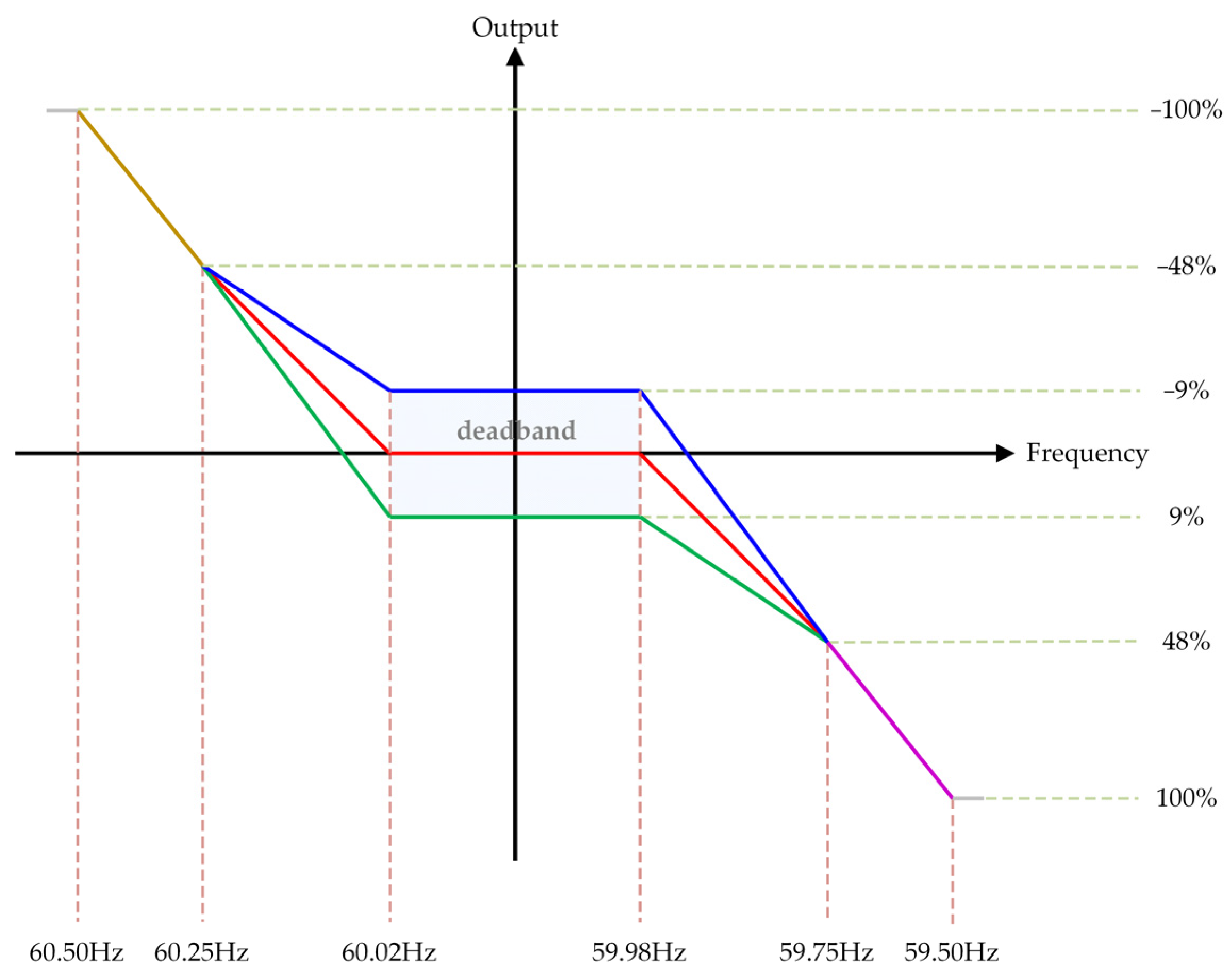
SOC to protect the energy storage system, the SOC control strategy in the E-dReg control strategy is defined within the range of 85% ± 2.5%. The program will assess the current SOC state and choose the most appropriate output/input power ratio slope curve. If the current SOC state is higher, it will select a slope range with a higher output and a lower input; conversely, if the SOC state is lower, it will choose a slope range with a higher input and a lower output. The selection of the output slope for each SOC range is illustrated in
Figure 9. Additionally, two new limiting conditions have been added for SOC during the execution of the energy transfer schedule for charging and discharging actions. The limiting conditions for charging and discharging protection are expressed in Equations (2) and (3). When the SOC is less than or equal to 82.5%, the slope for output calculation is determined based on the green segment. For SOC falling within the range of greater than 82.5% but not exceeding 87.5%, the slope for output calculation is based on the red segment. Finally, when the SOC exceeds 87.5%, the slope for output calculation is determined based on the blue segment.
The inclusion of the charging protection limiting condition is designed to protect against and prevent the controller from repeatedly initiating charging actions at the edge of the target SOC value during the charging schedule period. When executing the charging schedule, if the SOC reaches 85%, the charging action will be stopped. It will only be allowed to resume when the SOC drops below 80%. Here,
represents the scheduled amount of energy transfer for that second.
The discharge protection limiting condition is designed to protect against and prevent the controller from repeatedly initiating discharge actions at the edge of the target SOC value during the discharge schedule period. When executing the discharge schedule, if the SOC drops below 10%, the discharge action will be stopped. It will only be allowed to resume when the SOC rises above 15%.
In Equations (2) and (3), the output of the first two terms is both zero, resulting in seemingly identical outcomes. This design choice was made to prevent the controller from repeatedly starting and stopping discharging actions at the target SOC edge. These conditions provide a buffer space to prevent the controller from repeatedly discharging and stopping actions at the edge values of the SOC.
3.2.3. Charging/Discharging Control Computation
The E-dReg adds the function of energy transfer on top of the frequency regulation action in dynamic frequency regulation. Therefore, the charging/discharging control calculation of the E-dReg control strategy in this paper is developed and designed based on the technical specifications of dReg0.5. Taking 60.00 Hz as the frequency reference for frequency movement,
Table 2 provides a corresponding comparison between the charging/discharging calculation and the output setting values. The control strategy will calculate the charging/discharging control quantity based on the current grid frequency and SOC status, selecting different slope curves for computation. The calculation of the charging/discharging control quantity will be performed using the slope-intercept form to determine the slope and intercept of the curve, as shown in Equation (4). Here,
represents the output power,
represents the slope,
represents the current frequency, and
is a constant representing the intercept of the power axis.
When not within the time frame of the energy transfer schedule or without receiving an emergency dispatch directive, the charging/discharging actions of the enhanced dynamic frequency regulation reserve are the same as dynamic frequency regulation, involving only the execution of frequency regulation actions. However, during the energy transfer schedule or upon receiving an emergency dispatch directive, the charging/discharging control quantity at that moment is the sum of the frequency regulation control quantity and the scheduled energy transfer amount, as expressed in Equation (5). Here,
represents the dReg0.5 execution capacity for that second, and
represents the scheduled energy transfer amount for that second.
When dynamic frequency regulation actions and energy transfer are executed simultaneously, a conditional check needs to be added before the output, as shown in Equation (6). The purpose of this check is to avoid exceeding the daily awarded capacity when the execution capacity of frequency regulation actions is added to the scheduled energy transfer amount. If the sum of both exceeds the daily awarded capacity, the output is limited to the daily awarded capacity to ensure the safe operation of the system. Moreover, assuming a frequency reference of 60.00 Hz, if the current system frequency is below 59.50 Hz or above 60.50 Hz and there is an ongoing energy transfer scheduling action, the action needs to be paused for 900 s and directly switched to dReg0.5 mode. The energy transfer action can only resume after a 900 s delay, as shown in Equation (7). Here,
represents the awarded capacity for that hour.
3.2.4. Calculation of the Execution Quality for E-dReg
The execution quality of E-dReg and dynamic regulation reserve (dReg) is calculated using second-by-second performance measurement (SBSPM). The calculation is based on the sum of the dReg0.5 capacity and the energy transfer scheduling capacity that should be executed in that second, as shown in Equation (8) [
31], where
represents the measured value in the transaction table for that second.
Using
Figure 10 as an example, assuming the current frequency is
and considering the output scenario of
, the current output power should fall between points
and
. Therefore, if the current output power is at point
, the SBSPM at this moment is 100%, and if the current output power is at point
, the current SBSPM is
.
4. Test Results and Discussion
The developed E-dReg controller in this paper is designed and developed based on the relevant specifications provided by the Taiwan Power Company. Specific constraints and control strategies for E-dReg are proposed to enable the controller to adjust the grid frequency and control the transfer of electricity during peak and off-peak periods. In our research, LabVIEW predominantly functions within a tailored industrial computing ecosystem. LabVIEW 2018 software is deployed on the IPC, serving as the platform for code execution, data capture, and device control.
In the experimental testing of this paper, measurements were conducted using CPM-80 and CPM-72 to measure frequency and power parameters. The testing specifically included the complete control actions of E-dReg and the execution of emergency dispatch capacity instructions from the Taiwan Power Company. Through the analysis of various test results and data, the paper discusses and explains the entire execution process of E-dReg control for frequency regulation and electricity transfer.
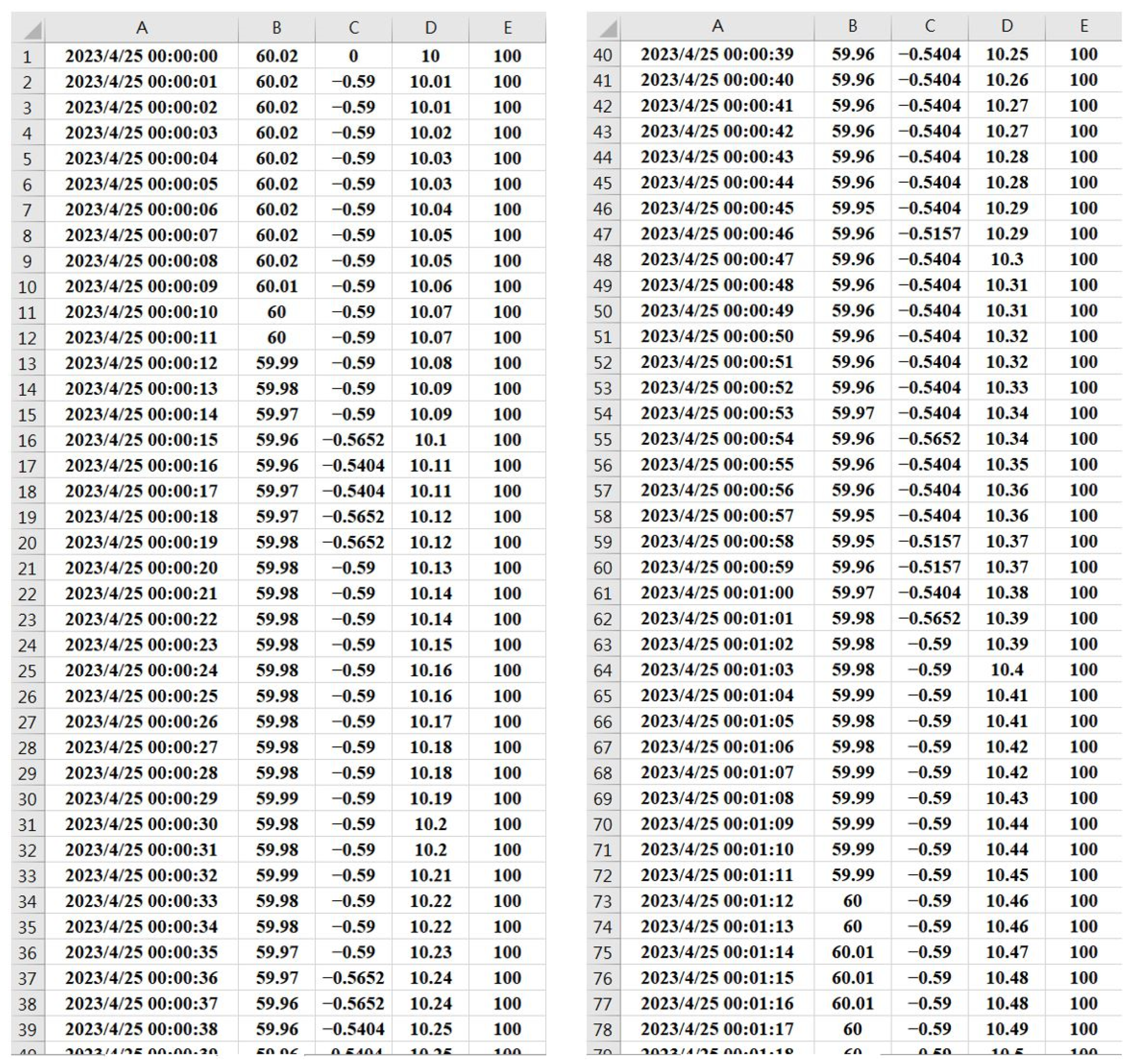
During actual testing, we utilize the programming archival function to record the frequency and corresponding output power ratio (
) every second for the entire day. The archived data include the frequency measurements, output power ratio, and other related electrical parameters collected throughout the testing period. The schematic diagram of the archived raw data is shown in
Figure 11. Subsequently, we will utilize these archived data to generate the waveform diagrams presented in
Section 4.
4.1. Test Results of E-dReg Control Strategy
To validate the proposed control strategy for E-dReg in this paper, the control strategy will be implemented within the controller in this section’s control tests. Through actual 24 h frequency regulation control and electricity transfer scheduling, data obtained from the real control tests will be analyzed to observe the data variations in frequency-corresponding output and SOC. Additionally, the execution efficiency of the E-dReg controller will be evaluated by examining the system benefit to schedule performance metric (SBSPM) at the end of the full-day operation.
In this test, the E-dReg controller was continuously operated for 48 h, spanning two days. The reference frequency for the test was based on the frequencies observed on April 27 and 28, 2023, throughout the entire day. The electricity transfer schedule was configured with a charging schedule from 00:00 to 04:00 and a discharging schedule from 16:00 to 20:00. The charging capacity was set to −2.5 MW, and the discharging capacity was set to 2.5 MW. The test involved scheduling the maximum electricity transfer capacity at 50% over four consecutive hours to observe the control performance and the overall variation in SOC resulting from the control strategy.
The actual control test results for E-dReg are presented in
Table 3 and
Figure 12,
Figure 13,
Figure 14 and
Figure 15.
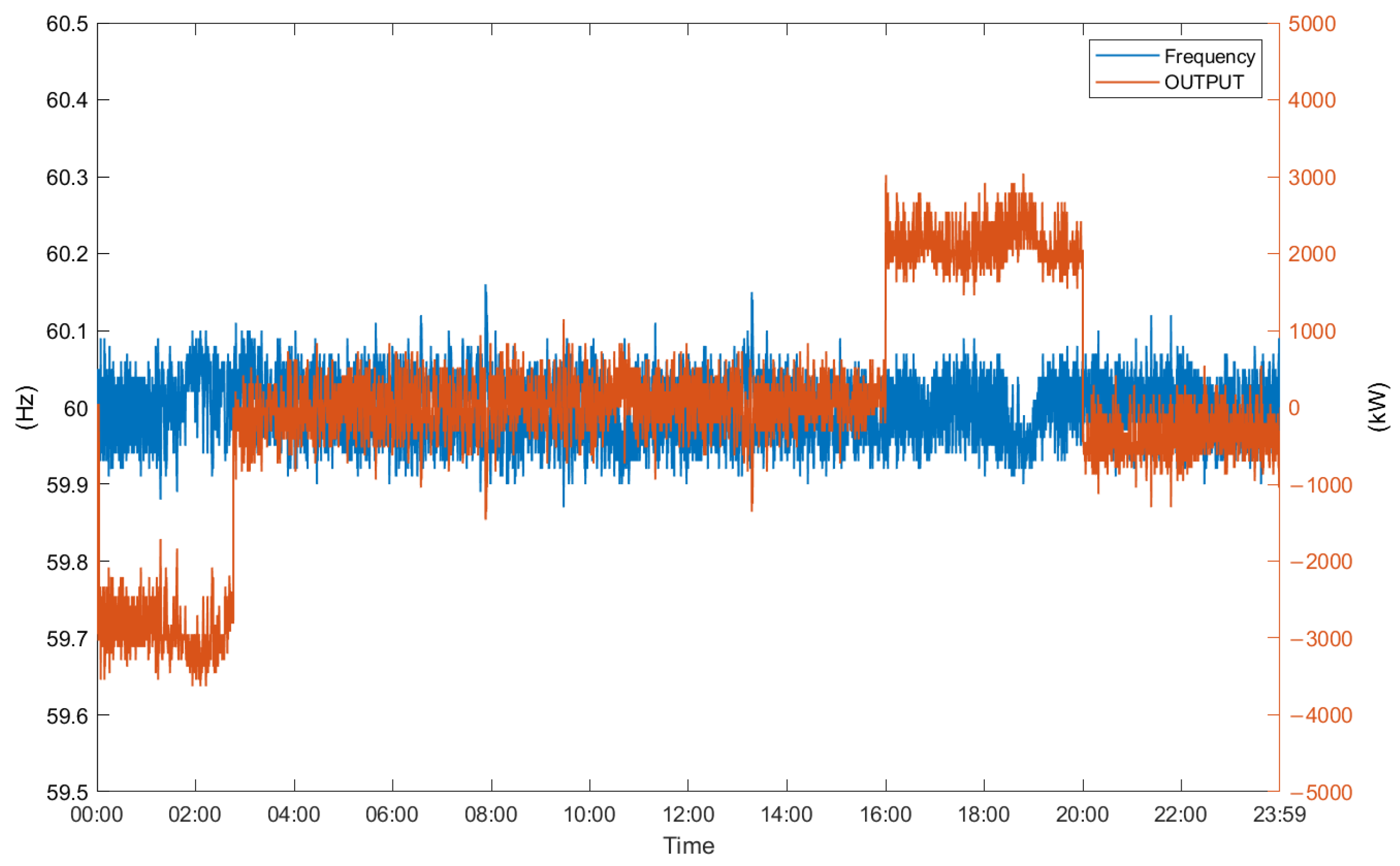
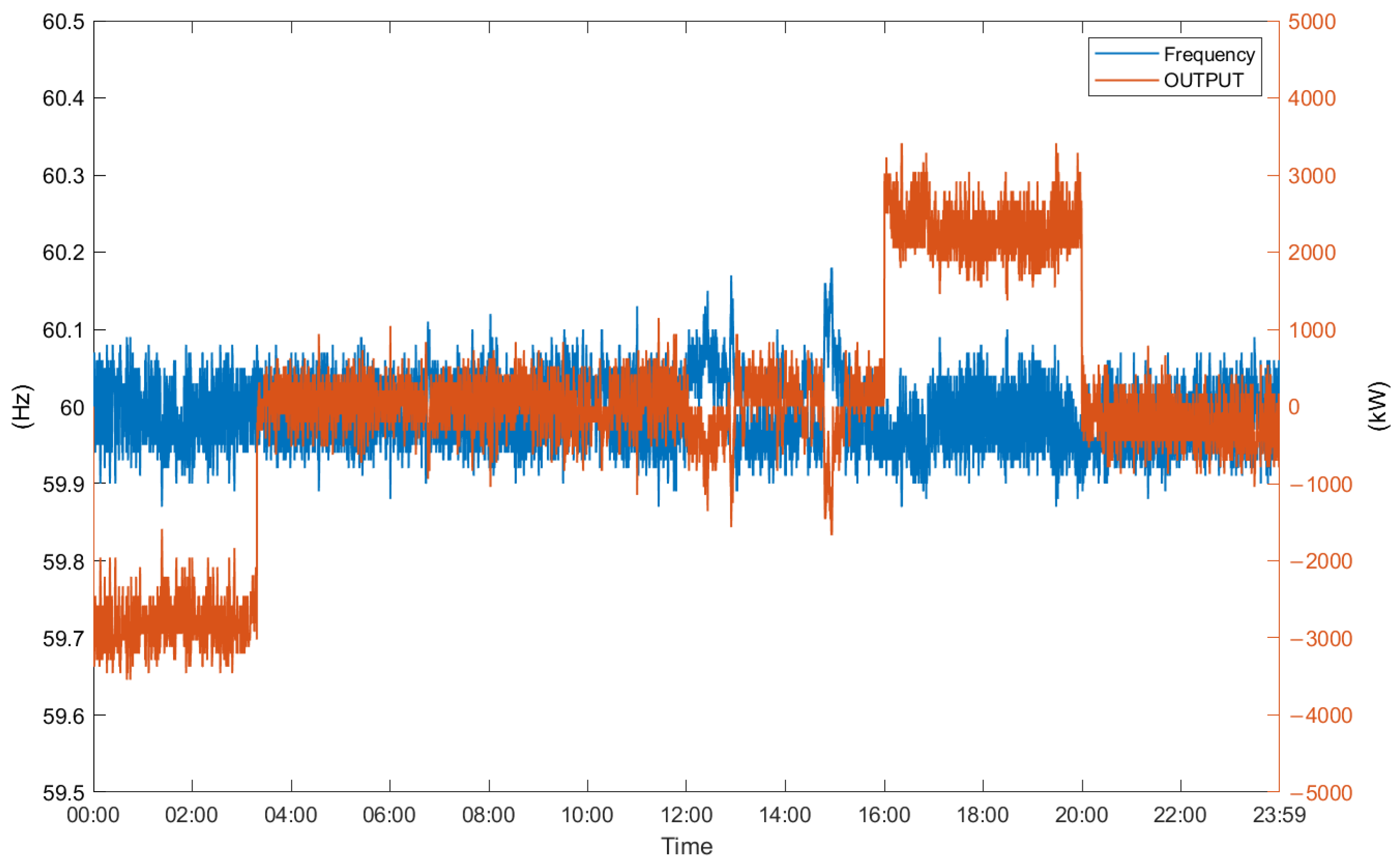
Figure 12 and
Figure 14 depict the curves of the actual measured frequency corresponding to the output power under the controller with the control strategy proposed in this paper. In both curve charts, the output power changes with the frequency every second. Within the scheduled energy transfer periods, as set, the baseline of the output power is observed to undergo upward and downward changes, indicating the execution of charging and discharging energy transfer control actions during the scheduled periods.
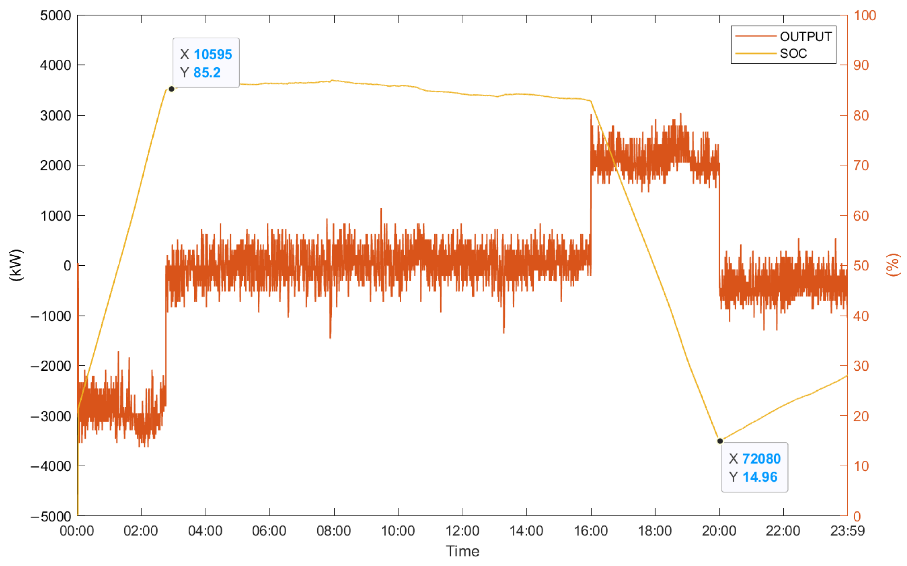
Figure 13 and
Figure 15, respectively, depict the curves of the output power corresponding to the SOC after testing. From these two charts illustrating the SOC variations, it can be observed that during the charging period, the SOC baseline is charged to the set 85% by the frequency regulation strategy before stopping the charging action. This clearly demonstrates the protective effect of the added SOC upper and lower limits. Additionally, after the discharge schedule ends, it can be observed that the SOC still remains at 13.15% and 14.96%. All fall within the range set by the control strategy. Finally, it can be clearly observed from
Table 3 that the SBSPM execution rates for the two control tests are consistently maintained at 100%, with no occurrences below 100%. This confirms that the E-dReg control strategy proposed in this paper can effectively perform dynamic frequency regulation and energy transfer scheduling for an extended period. It keeps the SOC within the designed range and ensures that the controller successfully maintains a 100% execution rate throughout the day.
4.2. Action for Receiving Emergency Dispatch Command
In this section, to test the control capability of the E-dReg controller when receiving an emergency dispatch capacity command from the Taiwan Power Company during the service period, a simulator will be used to send the emergency dispatch command signal. The signal will be initially received by the energy management system (EMS), and then, through MODBUS TCP, the dispatch command will be transmitted to the E-dReg controller. Upon receiving the emergency dispatch command, the E-dReg controller will perform emergency dispatch control actions according to the specified capacity and designated time.
This test involved continuously testing the E-dReg controller for 48 h over two days, referencing the frequency measurements taken throughout the day on April 29th and 30th, 2023. During the execution of service control actions, random emergency dispatch commands were sent for testing. Through the random dispatch commands, the test aimed to observe the control performance and execution quality of the E-dReg controller.
The actual control test results for the E-dReg controller receiving emergency dispatch commands are depicted in
Figure 16,
Figure 17,
Figure 18 and
Figure 19.
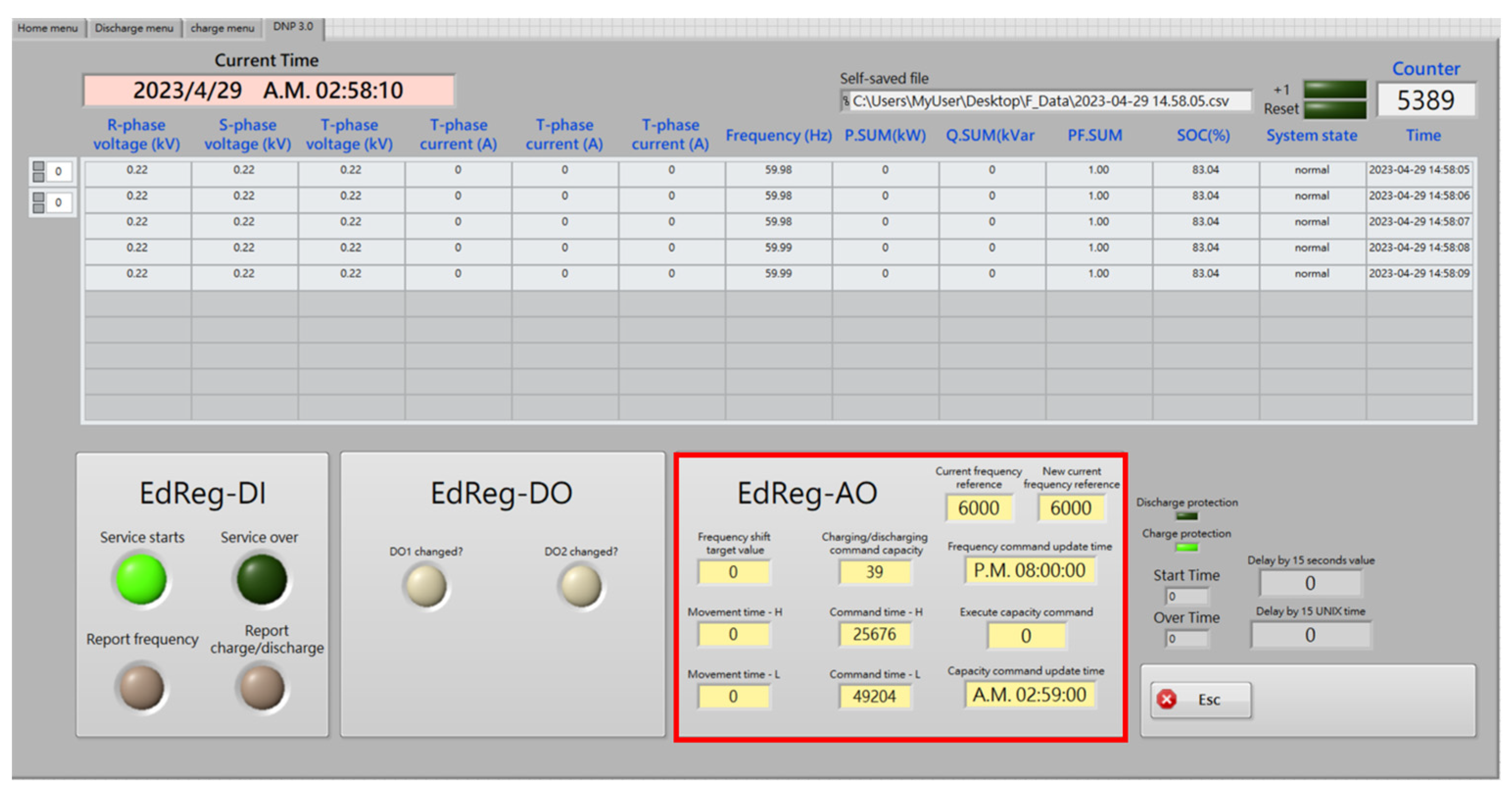
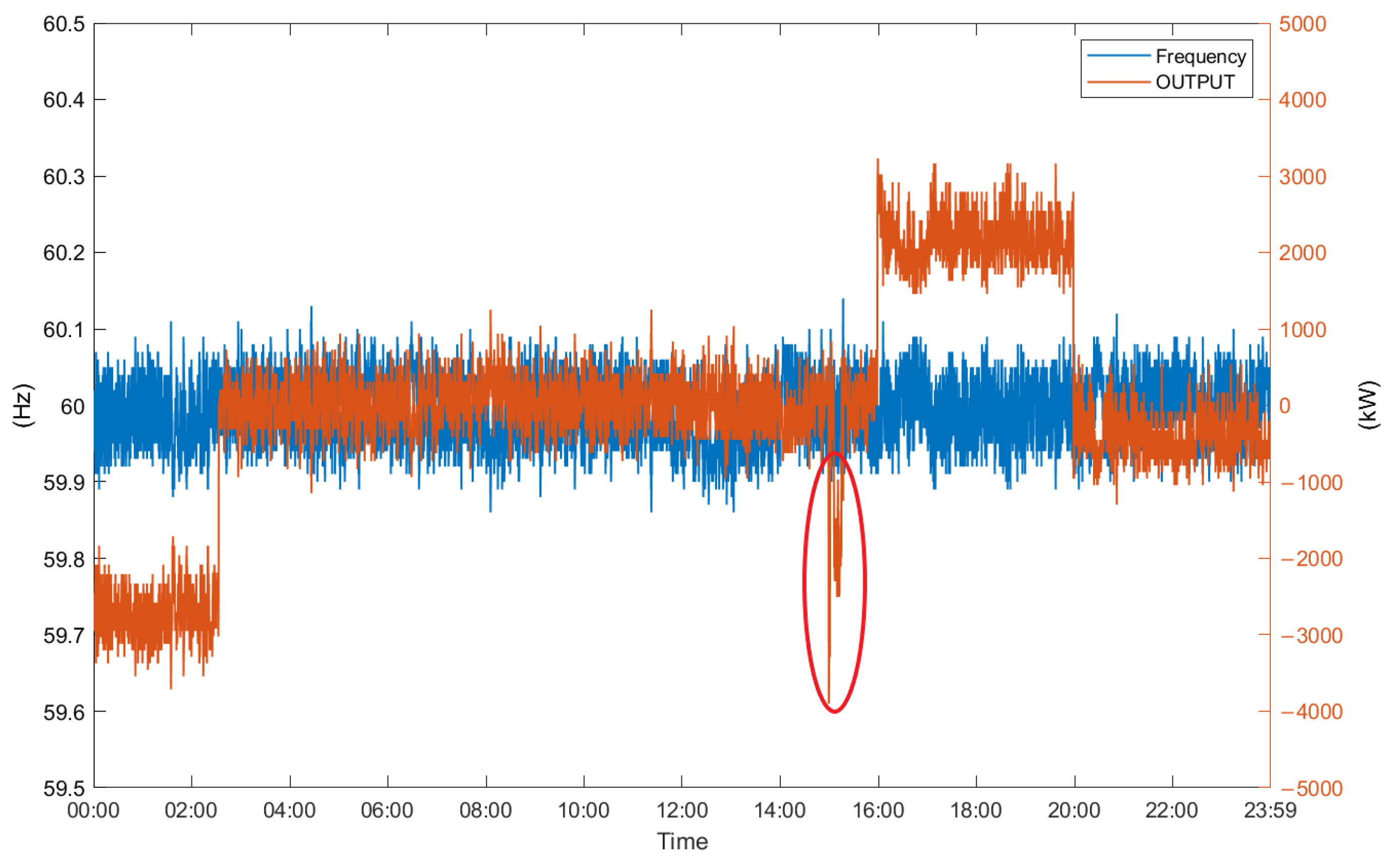
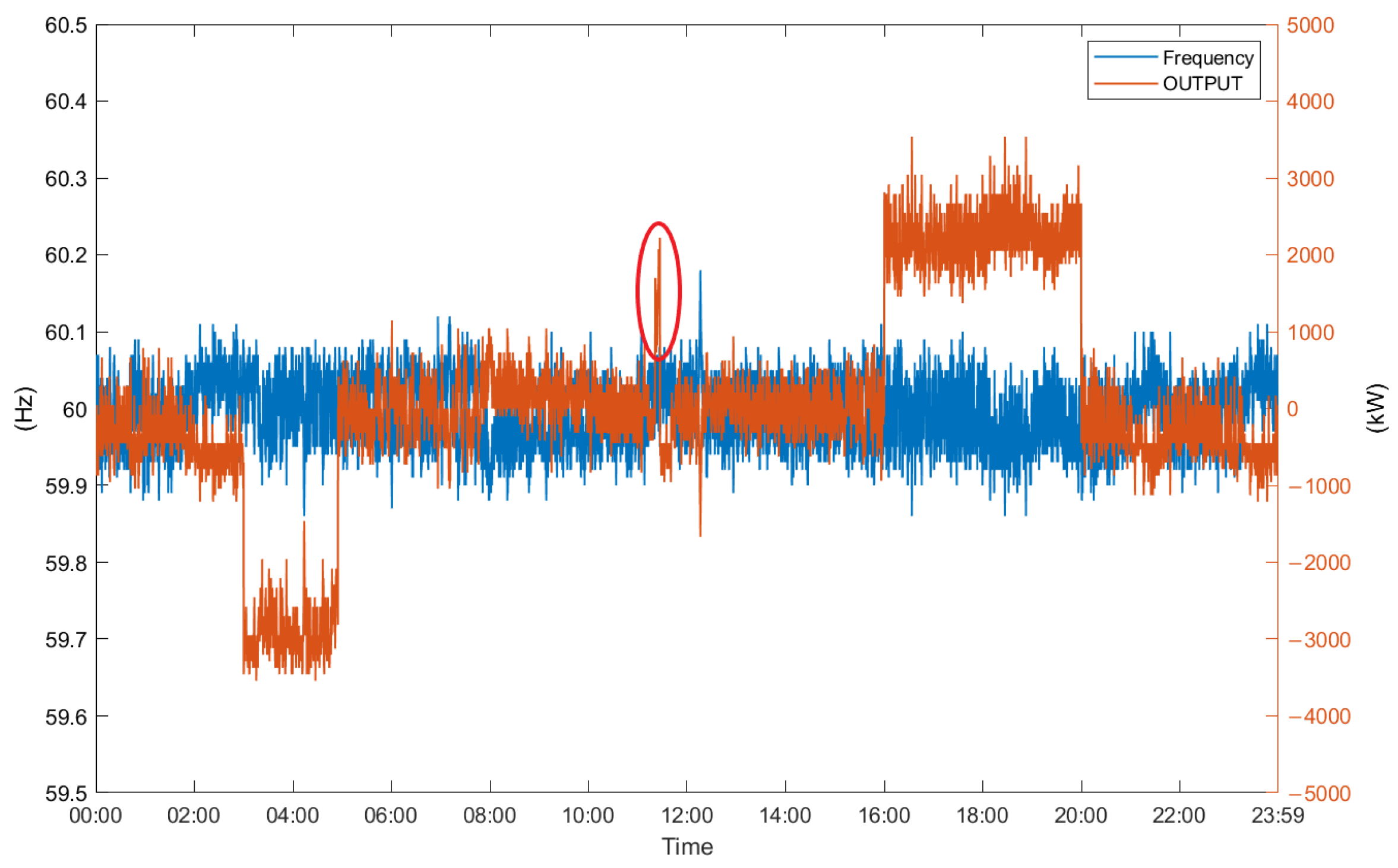
Figure 16 and
Figure 18 illustrate the human–machine interface (HMI) of the E-dReg controller in the EMS. From these two figures, it is evident that when the E-dReg controller receives the emergency dispatch command simulated by the emulator, the interface allows monitoring of the capacity to be executed and the commencement time of the execution. In
Figure 17 and
Figure 19, the curve charts of output power corresponding to frequency show a sudden change in the horizontal part highlighted by red circles. This change indicates that the controller is executing the emergency dispatch command. Similarly, the SBSPM execution rate consistently remains at the 100% level. This confirms that the E-dReg controller can receive emergency dispatch commands while in operation and successfully complete the control actions without affecting the execution quality.
5. Conclusions
In response to the potential impact of the gradual integration of intermittent renewable energy sources into the power grid, this study has developed a control system specifically for the E-dReg controller. The purpose of this controller is to effectively mitigate the potential impacts and disturbances caused by the integration of a large amount of renewable energy into the grid. This is crucial to maintaining a balance between power generation and load consumption, ensuring the stable operation of the power system.
In the E-dReg control system, a flexible energy transfer scheduling feature has been incorporated, building upon the foundation of dynamic regulation reserve (dReg0.5). The objective is to enhance the efficiency of dReg0.5 utilization and extend the primary operating range of the energy storage system. The E-dReg controller, developed in this paper, takes into account the charging state of the energy storage system. It can sense the frequency within one second and perform precise frequency regulation control actions. Moreover, it is equipped to execute peak-shifting energy transfer scheduling within specified time intervals. Furthermore, by integrating with an EMS capable of receiving emergency dispatch commands from the Taiwan Power Company through a telemetry communication module, the E-dReg controller can accurately execute the charge and discharge actions specified in the emergency dispatch instructions. The proposed E-dReg control strategy in this paper enables the controller to maintain the SOC of the ESS within a safe and ideal range while accurately performing frequency regulation, energy transfer, and emergency dispatch controls. Over extended periods of operation, the controller consistently achieves a high execution quality level of 100%, ensuring competitiveness in the future ancillary services market.


