1. Introduction
In an ever-evolving technological landscape, the development of new technologies demands the availability of rapid and efficient testing procedures. These procedures play a crucial role in expediting the validation process, ensuring the timely introduction of developed technologies to the market. This is essential to prevent the risk of technological obsolescence, which may occur if the testing procedures linger unnecessarily. In the context of rehabilitative robotics, over the past decade, several exoskeletons for upper limb rehabilitation were proposed (Float [
1], Alex [
2], Armeo [
3], CleverArm [
4] AnyExo [
5], Harmony [
6], Aramis [
7]). Despite their significant differences, these devices share a common technological foundation: design a device that can be coupled with the human body, closely resembling the physiological movements of the shoulder and scapular complexes. Some unconventional implementation attempts have been presented so far, such as the Limpact [
8] hydraulic exoskeleton, which remained in a stage of prototype development. Most of the rehabilitation devices on the market (Armeo Power [
3], Harmony [
6]), or in an advanced stage of development (Anyexo [
5], Float [
1]), are equipped with brushless DC motors, harmonic drive transmission and SEAs (Series Elastic Actuators).
Several of the aforementioned devices followed a Rapid Control Prototyping (RCP) approach in their early stages of development. Literature offers a variety of platforms for the control design: ARMin [
9] runs on MATLAB/Simulink XPC target (now known as Simulink Real-Time), ANYexo runs on a control PC running a Linux operating system and interfaces with the hardware by EtherCAT communication; Harmony is operated by a real-time control system running Linux patched with RT-Preempt and communicates via EtherCAT. Furthermore, these exoskeletons share a similar system architecture, with a central control unit overseeing the coordinated actions of various motor control boards distributed throughout the robotic structure. In terms of control strategies, a remarkable consistency can be observed. These systems offer a range of control modes, from precise position control for passive mobilizations to more sophisticated and adaptable approaches like impedance and admittance control, commonly used in rehabilitative robotics to guarantee a compliant human-machine interaction [
10]. In the development process of rehabilitative devices, RCP and Hardware In the Loop (HIL) emerge as pivotal approaches, allowing the quick implementation and testing of complex control strategies.
RCP approach enables early testing on hardware, even in a prototype stage, allowing for a swift assessment of how the control algorithms perform in a real-world setting. Additionally, RCP facilitates code reusability across different testing platforms, leveraging flexibility in hardware integration. The real-time application allows quick modifications to the control architecture.
By combining HIL and RCP, the developed software can be deployed and tested in a realistic environment. This approach allows for an early validation of both hardware and software characteristics, encompassing the testing of potential faults. The synergy between HIL and RCP supports parallel development of hardware and software, with continuous updates and testing. This concurrent approach increases the number of design and test iterations, expediting the definition of final device characteristics and, in turn, reducing time consumption and overall costs.
Several platforms are available for RCP and HIL applications. Among the commercial development environments there are: (i) dSPACE RCP by dSPACE [
11], which exploits hardware and software tools to expedite the prototyping, testing, and iteration of control strategies in diverse domains; (ii) MathWorks, through MATLAB/Simulink Real-Time, enables real-time execution of Simulink models on dedicated hardware like Speedgoat’s real-time target machines [
12], making it ideal for comprehensive model-based control testing; (iii) National Instruments (NI) VeriStand [
13] provides a software solution for configuring real-time testing applications. Additionally; (iv) Opal-RT (RT-LAB) [
14], ETAS (LABCAR) [
15] and Quanser [
16] offer real-time simulation platforms tailored for both HIL and RCP applications, serving as crucial tools for testing embedded control systems.
In this work, authors propose a RCP-HIL methodology targeted at rehabilitative robotics applications. The testing of the control architecture performances for an upper-limb exoskeleton prototype are presented. The peculiarity of the proposed method lies in the early adoption of a unified development environment and a single programming language. In the context of this project, the authors exploited MATLAB tools by MathWorks (Natick, MA, USA). However, the same methodology can be leveraged in any other RCP development environment.
2. Hardware Platform for RCP-HIL Test
2.1. Exokeleton Prototype
The hardware platform is a 6-Degrees-of-Freedom (DoFs) prototype of an upper limb exoskeleton (
Figure 1 and
Figure 2). The prototype consists of two joints for the scapular complex (J1, J2), three joints for the shoulder complex (J3, J4, J5), and one joint for the elbow (J6). The mechatronics includes Series Elastic Actuators (SEA [
17]) and motor control driver boards (EPOS4 Compact 50/8 (Maxon Group)). The control boards, mounted directly on the joints, are then connected, as well as the SEA sensors, via CAN (Controller Area Network) to the central control unit (Speedgoat Baseline real-time target machine [
18]). This is further connected to a panel PC where the control interface is displayed.
2.2. Central Control Unit: Real Time Target Machine for RCP Development
To facilitate real-time simulations, a Real-Time Target machine has been employed, with Speedgoat serving as the platform for all conducted test. Speedgoat offers high performances thanks to multi-CPU target computers. It can be adopted in different areas like RCP and HIL systems. It is specifically designed to integrate with Simulink and Simulink Real-Time tools from MathWorks. This machine enables the execution of real-time applications developed within the MATLAB Simulink environment. The incorporation of Speedgoat Simulink driver blocks within the model streamlines the process, allowing for the automatic generation of real-time applications. Subsequently, these applications are downloaded and executed on the machine with ease. The target machine has integrated communication ports that enable the device to interact with the outside world. Speedgoat can communicate with other devices trough external ports, for the purpose of our experiments the CAN and Ethernet ports have been used, but many others communication protocols are available meeting the designer preferences (EtherCAT, PWM, SPI, I2C, SENT and more [
18]).
3. Control Design Methodology
The control strategy involves implementing all control levels (low, medium, high levels) within the same environment (MATLAB R2021b). Thanks to the use of various tools, it is possible to obtain a unique control model that includes setting up control drivers, acquiring and processing data from the mechatronic structure, and designing control algorithms (implemented following state machine logic). The steps of the proposed methodology are described below.
3.1. Geometric Model Description
The robotic kinematic chain can be described using the Denavit-Hartenberg convention (DH) or the modified Denavit-Hartenberg (mDH) convention [
19]. For each frame (corresponding to a joint), it is possible to assign dynamic properties such as mass, center of mass, and the inertia tensor. To compute these properties, a CAD model should be utilized to facilitate the calculation of inertial properties with respect to the different joint reference frames. Subsequently, a rigid body tree (RBT) model (a geometric model characterizing both the kinematics and inertial properties of the robot) can be designed. The authors propose, as an example, the adoption of CREO PTC [
20] as CAD software to obtain the dynamic characteristics and MATLAB Robotic Toolbox to build the exoskeleton rigid body tree model, as shown in
Figure 3a. This RBT model is imported into the Simulink model and utilized to real-time compute the direct and inverse kinematics and the gravity torques to be compensated at each joint. The aforementioned procedure is described in
Figure 4.
3.2. Design of the Low Level Control
The setup of the EPOS boards’ controllers is carried out with the following steps: (i) communication of the motor specifications (torque gain, resistance, etc), (ii) communication of the PID gains for the position, velocity and current loops (that operates at
kHz), (iii) communication of the desired operational limits. The communication protocol used to work with EPOS4 is the CANopen protocol. Inside the CANopen network the EPOS4 controllers are controlled as child nodes and coordinated by the Simulink model running on Speedgoat real time target machine. CAN protocol has been setup by employing IO614 reading and writing modules on Speedgoat Baseline Real-Time Target Machine [
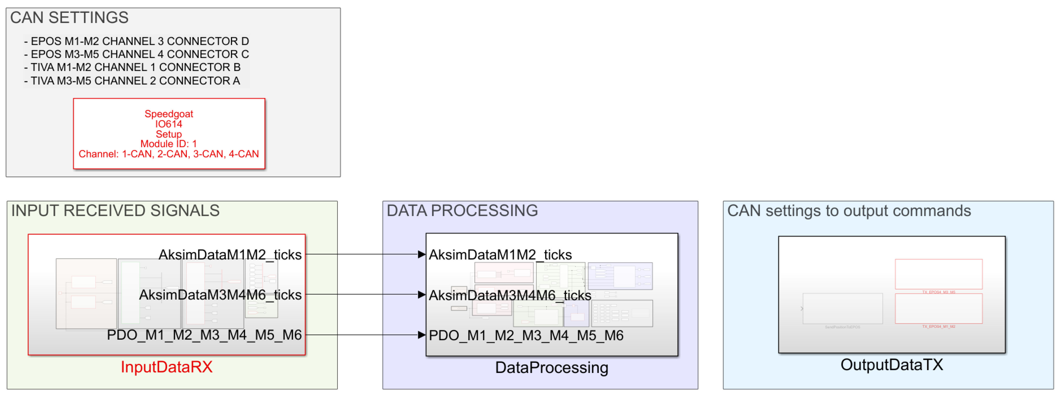
18]. With reference to the top layer of the model (
Figure 5), CAN SETTINGS module is built to set up CAN connection exploiting CANopen protocol; INPUT RECEIVED SIGNALS module manages the input signals from SEA sensors and EPOS boards (acquired at
kHz); CAN SETTINGS TO OUTPUT COMMANDS module sets up all the output control signals (computed and provided at
kHz) to communicate via CAN with the sensors and EPOS motor driver boards.
3.3. Design of the Mid-Level Control
Exploiting Simulink and Stateflow enables the straightforward implementation of multiple state machines to characterize the operational modes of the exoskeleton and potential state transitions. With reference to
Figure 5, the dedicated module is DATA PROCESSING, that is the core module where all the control is implemented by means of control algorithms and state machines. The processing unit describes all the possible states transitions between the different behaviours of the device. The tasks performed in the Data Processing subsystem are: (I) Estimation of the SEAs torques; (II) Setup and reaching of the homing position (resting position of the exoskeleton); (III) Managing of the different working modes (passive exercises, exercise with compliance achieved thanks to impedance control, transparency, learn and replay); (IV) Computation of the pose of the exoskeleton end-effector; (V) Computation of the scapular elevation coupling following the method suggested in [
1] The scapular elevation is function of the shoulder flexion. Once the shoulder flexion overcomes 60°, refer to
Figure 3a, J2 is coupled with J5 with a ratio 1:3); (VI) Trajectory generation; (VII) Computation of the gravity torques from the robot dynamic model; (VIII) Torque control target generation (friction compensation, impedance, transparency).
Different control strategies can be implemented to treat and support patients during rehabilitative therapy. During the initial phases of rehabilitation, it is reported that rigid guidance can help the subject understand movement paths and maintain high training intensity [
21]; however, as the patient’s voluntary motor control increases, rigid control becomes less suitable, and collaborative forms of control strategies are suggested [
10,
22,
23].
Dealing with complex robotic systems that interact with the human body (Human-in-the-loop control) [
24], where the subject is considered the controller [
25], it is essential to develop control strategies capable of making the robot compliant with the user’s movement intention. Complex approaches based on modelling dynamic nonlinear interaction (which emphasize the importance of neuromuscular actuation mechanisms as a source of nonlinearity in the human controller) and on identifying movement intention have being explored [
25]. A more commonly used approach is the implementation of partially assistive control strategies, which enable human-machine interaction based on reading sensors placed at the user-device interface [
26,
27,
28].
Assistance-as-needed (AAN) [
29], control strategies allow active control of exoskeleton motion by the impaired subject, supporting patient movement based on the level of residual motor capabilities. A common solution to provide AAN to the impaired limb is to transition from rigid control to compliant control. These controls exploit impedance/admittance algorithms to make the device compliant to user movement [
26,
30]. Additionally, by modeling the dynamics of the interaction, these controls allow the implementation of variable levels of support selectable according to the patient’s condition, as proposed for the Harmony [
6] and AyExo [
5] devices. Moreover, in the work proposed by Proietti et al., the importance of good transparency implementation (specifically compensation for gravity and robot dynamics) is emphasized, as it directly correlates with the exoskeletons’ ability to provide correct assessment of the quality of human motion [
10].
Following the aforementioned insights provided by the literature, the authors decided to focus on three main control strategies: passive user mobilization, compliant and modular assistance, and transparency. Going from the first to the last modality, the goal is to increase the user engagement and decrease the exoskeleton assistance.
3.3.1. Passive User Mobilization
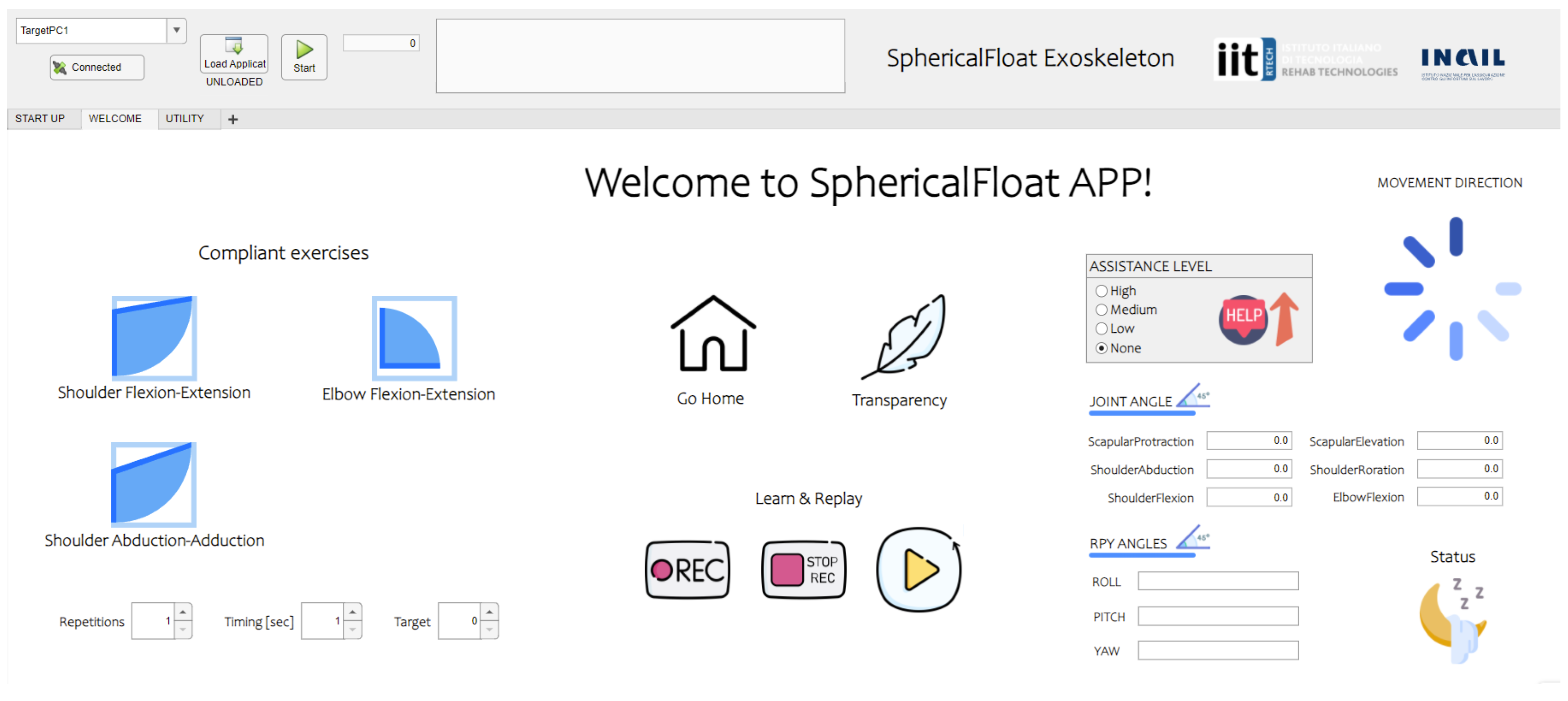
This working mode exploits the position control. The exoskeleton moves the human limb in a rigid way, without keeping into account the interaction forces. A target trajectory is provided for each joint. The possible exercises are: shoulder flexion-extension, shoulder abduction-adduction and elbow flexion-extension. By means of the graphic user interface (
Figure 6) it is possible to select the desired number of repetitions, timing (exercise duration) and maximum target angle. It is also possible to replicate, in position control, a recorded exercise. The model has a dedicated Stateflow state machine that can be used to perform the learn and replay. By exploiting the GUI buttons, it is possible to start the exercise recording (the exoskeleton goes in transparency mode and can be moved freely). Then joint position data are recorded, stored and used as target trajectory for the replay.
3.3.2. Compliant Exercises: Impedance Control to Provide Modular Assistance during Rehabilitative Exercises
Impedance control can be exploited to support the patient in performing voluntary movements. Impedance control manages the capacity to exchange force between the controlled system and the subject or the environment. Linear impedance parameters, like stiffness and viscosity, are described as second-rank twice covariant tensors [
31]. This impedance embodies the correlation between force and motion dictated by the supervisor, encompassing both the static force/displacement relationship and any dynamic terms necessary for controlled dynamic behavior [
31]. Essentially, it dictates whether the robot exhibits rigidity or compliance upon interaction with external objects or surfaces. It belongs to the category of partially assistive controls [
10], aiming to not only provide physical support but also to maintain the subject’s motivation, training intensity, confidence in using the affected limb, and prevent negative reinforcement [
21]. A tunable support level can be provided depending on the residual motor functionality of the user. The assistance level can be selected on the GUI, the target trajectories can be the ones of predefined exercises or a recorded complex trajectory stored during the learn-and-replay procedure. Impedance control can be used to ensure safety during human-machine interaction: it allows to dissipate torques and forces at joint level and not to the external environment.
By tuning stiffness (
) and viscosity (
), it is possible to provide a modular assistance increasing the user engagement while decreasing the provided support. The adopted impedance algorithm is developed in the joint space.
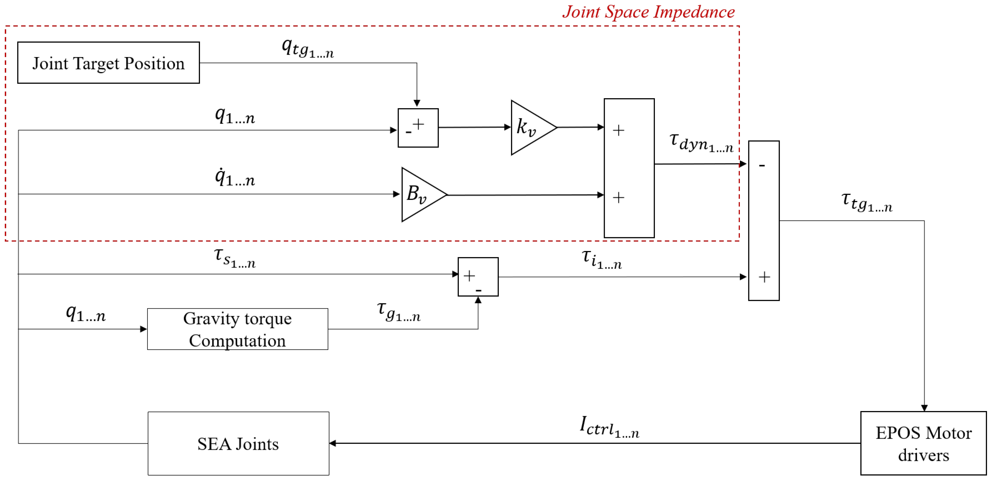
For each joint the control scheme shown in
Figure 7 is applied. Simulink allows to fully explore the potential of real time computation. With reference to
Figure 7, the Joint target position is real time computed for the standard exercises trajectory as a linear interpolation between the start and end position, set by the user into the GUI. This has to be performed in the desired amount of time and repeated for the selected number of repetitions. The trajectory can also be recorded during a learn process. The joint actual position and speed are provided from EPOS board. For this implementation a reference velocity
has been considered at all times. The sensed actual torque is computed by the model starting from the SEA sensor encoders readings (measure of the SEA spring deformation
), as explained in [
17]:
respectively
and
are: the angular displacements after and before the spring, the mounting encoder offset,
is the linear model intercept and
k is the stiffness of the adopted compliant element. The gravity torque is obtained from a dedicated Simulink block of the robotic toolbox as explained in
Figure 4. All the aforementioned information is compared and elaborated to generate the control signals for the motor boards.
3.3.3. Transparency: Gravity and Friction Compensation
Transparency mode is implemented in order to let the user perform free movements, exploring the working space minimizing the exoskeleton weight and friction effects that can interfere with the smoothness of the performed movement. The motor control is performed in torque (current), the control signal is computed from the sum of different components: the gravity torque, the friction compensation torque and the interaction torque (obtained from the SEA sensed torque). This control exploits two different layers:
Gravity compensation: it is needed to compensate the gravity effect to avoid that the structure collapses under its weight, thus a reliable gravity compensation model is needed. The obtained rigid body tree model (
Figure 4) is exploited in Simulink by the Gravity Torque block of the Robotic Toolbox allowing to real-time compute, given a certain joints’ configuration, the gravity torques to be compensated.
Friction compensation: frictions can result in a lack of smoothness during the movement, especially at low speeds when static frictions need to be won. A Stateflow state machine has been implemented to evaluate, based on the actual motor speed, a compensatory friction torque used to overcome friction dissipation. The friction contribute is computed as , with parameter evaluated by the state machine in a dynamic way following Algorithm 1. is evaluated at each interaction. The highest compensation for overcoming frictions occurs at low speeds when static frictions need to be overcome. The coefficient remains constant within an accepted speed range for movement in transparency. If the motor speed exceeds a specified threshold, indicating that the joint is moving too fast, takes on a different value, increasing the viscous effect until reaching the maximum set velocity, thereby implying minimal support in overcoming frictions.
| Algorithm 1 Friction compensation: the algorithm implemented in the dedicated state machine for friction compensation involves monitoring the rotational speed of the joint. Depending on the speed value, the compensation effect is determined, mirroring the behavior of a damper. Specifically, if the speed is below a minimum threshold, denoted as , it indicates that the joint is initiating movement. To overcome initial static friction, the compensation effects against friction are amplified. Within a predefined ideal speed range for device activities, the compensation contribution remains constant. However, if the speed exceeds a high threshold, denoted as , a gradual effect begins to compensate less against friction until minimal compensation is achieved at the predefined maximum speed, . |
if then
else
if and then
end if
if then
end if
end if |
3.4. Design of the High Level Control
The deployed control model is integrated with a Graphic User Interface created using the MATLAB App Designer Tool. The GUI will serve as interface between the user, the control model and the real time target machine. Through this GUI, users can dynamically select and customize the exoskeleton’s behavior, issuing commands (
Figure 6) and monitoring key data for the prototype performance evaluation.
4. Results
Experimental tests were conducted to assess the performance of the 6-DoF device prototype (shown in
Figure 1). The device was tested in its various control modes. In the control modalities in which physical interaction was required, an unimpaired individual took care of moving and interacting with the exoskeleton system. Specifically, the kinematic mode was tested with the execution of proposed exercises, the assistance mode with different levels of support provided, and the transparency mode aimed at using the device without the perception of friction and gravity forces.
4.1. HIL Testing: Validation of Gravity Compensation Model
Real-time experiments have been conducted to validate the dynamic model obtained form the characterization of the Rigid-Body-Tree shown in
Figure 3a.
The test aims to verify the consistency between the torque estimated by the SEA sensors (obtained by evaluating the deflection of the elastic element) and the torque calculated using the dynamic model of the exoskeleton obtained with the methodology presented in
Figure 4. To evaluate the performance of the exoskeleton, authors decided to explore a wide portion of the workspace by moving the robot in transparency mode and recording the executed movement (learn and replay mode). This recorded movement is then executed by the exoskeleton without the presence of a user, in position control (so that the SEA sensors detect only the gravity torque and not the interaction torque with the user). From the collected data of the experiment, it is possible to perform a comparison between the measurement of the gravity torque obtained from the SEA sensors and the one estimated using the MATLAB Gravity Torque Toolbox (based on the characterized dynamic model).
In
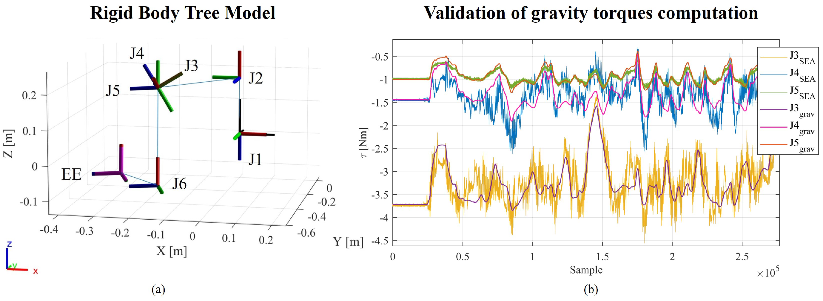
Figure 3b are shown the Gravity Torques computed from the dynamic model and recorded by SEAs for the spherical joint complex (J3, J4, J5). The computed RMSEs and absolute errors, between the SEA measure and the gravity compensation model are reported in
Table 1.
4.2. HIL Testing: Compliant Modular Assistance
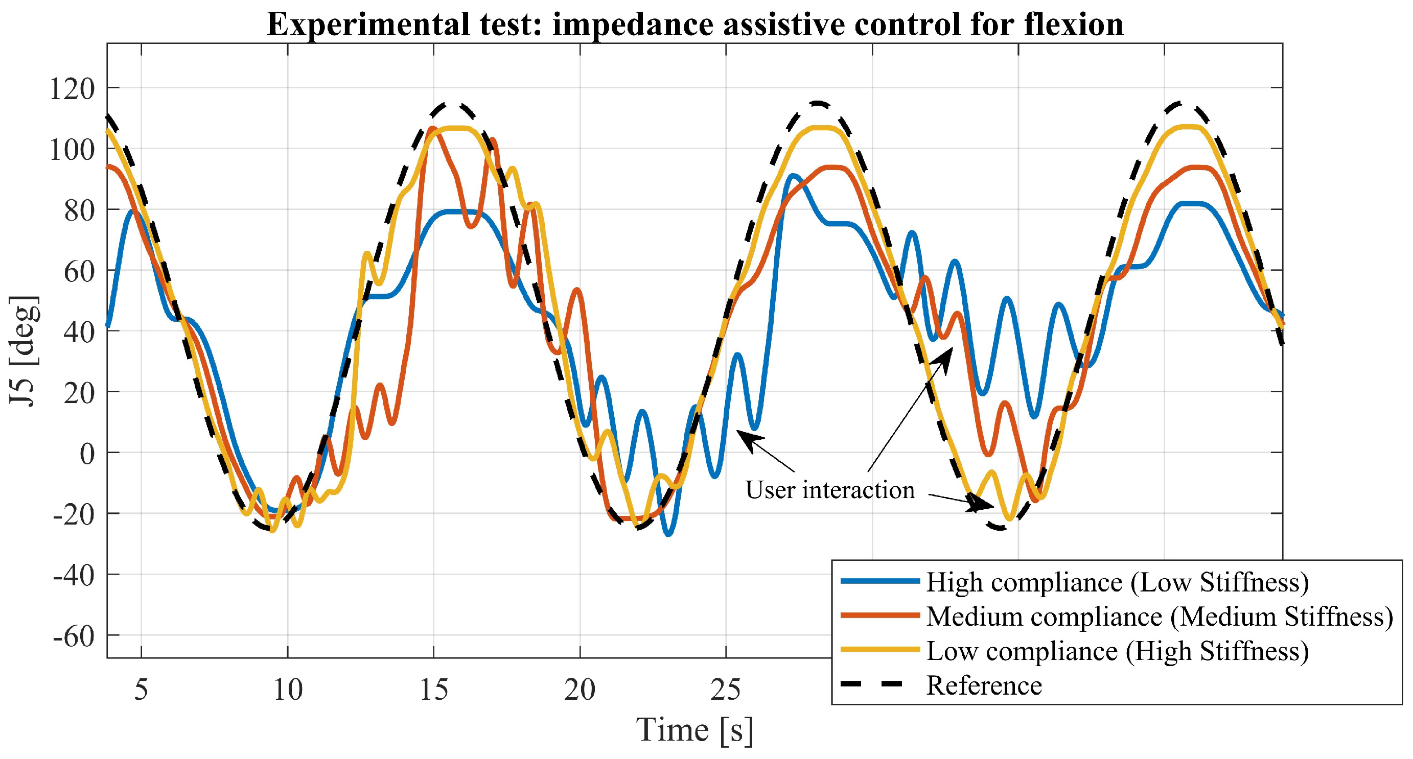
In the field of impedance control, a control has been developed with selectable levels of assistance (
Table 2) accessible through a graphical interface. The
Figure 8 illustrates test conducted at three different assistance levels during a shoulder flexion exercise, specifically focusing on joint J5, which plays a significant role in this movement. The graph in
Figure 8 displays both the target trajectory and the actual trajectories executed by the user, exploiting the dedicated joint, throughout the exercise in assistive mode.
5. Discussion
In this study, the authors introduced a methodology tailored for rapid control prototyping of control strategies in the field of rehabilitative robotics. Utilizing MATLAB-Simulink, the control architecture was exported and executed in real-time on the Speedgoat target machine: high-level code (Simulink) was automatically transformed into C/C++ (build duration: 0 h 5 m 15.516 s) code on a real-time target machine. Various control strategies, with a focus on those incorporating compliant control techniques such as transparent and impedance control, were tested to provide adaptable assistance to users.
The authors presented the hardware platform used to test the 6-DoFs upper limb exoskeleton (
Figure 1 and
Figure 2). The geometric model of the exoskeleton, obtained from CAD software, was utilized to design a rigid body tree model (
Figure 3a) encompassing both kinematic and dynamic properties.
Successively, the control model implemented in Simulink (
Figure 5), explaining its state machine logic and various functionalities, is presented. Additionally, they showcased the graphical interface designed to facilitate device usage and testing (
Figure 6).
Performance evaluation test (
Figure 3b) for SEA sensor readings and the dynamic model designed for gravity torque compensation yielded comparable results (see
Table 1). The observed errors can be attributed to inertial and viscous effects not accounted for in the proposed dynamic model, which relies on MATLAB’s Robotic Toolbox’s built-in function. The proposed model (as depicted in
Figure 4) only performs gravity compensation based on positions, neglecting inertial effects due to acceleration. However, within the context of rehabilitation, this compromise is acceptable given the typical low velocities and accelerations involved. Since the inertial properties of the system can be obtained from CAD, a future step could involve utilizing the rigid-body-tree to generate the mass matrix and also performing inertial component compensation.
Assistive control testing (
Figure 8), utilizing impedance in joint space (
Figure 7), was instrumental in selecting and testing various combinations of stiffness and viscosity. The objective was to achieve the tuning of modular assistance levels tailored to rehabilitation requirements.
The presented tests were conducted to evaluate the performance of the device, particularly to establish the exoskeleton’s ability to provide different levels of assistance to the user, thanks to the implementation of the proposed impedance control strategy. Experiments were conducted with three levels of assistance, adjusting stiffness-viscosity parameters of impedance control (values listed in
Table 2).
Figure 8 illustrates the results, with the black line representing the target trajectory for the joint, while the blue, orange, and yellow lines depict outcomes of tests conducted at different assistance levels. The observed oscillations result from human interaction with the robot. By assigning a different spring-damper behavior, variable assistance could be selected. Lower assistance (high compliance and low stiffness) permits increased interaction with the robot, allowing users to deviate significantly from the target trajectory. Conversely, higher assistance (low compliance and high stiffness) ensures better adherence to the target trajectory, albeit with limited interaction with the device.
In this context, RCP facilitated various interactions to experimentally evaluate suitable pairs of and by dynamically adjusting parameters in real-time and observing the device’s behavior.
While the proposed method offers simplicity and abstraction from low-level issues, facilitating rapid testing of control models, it has limitations. Specifically, its inability to access the underlying algorithms of the adopted functions and toolboxes. Despite this limitation, the authors believe that this method strikes a balance between ease of use and customization, prompting users to consider the trade-offs between simplicity, detailed control and flexibility.
A crucial aspect remains finding useful metrics to objectively evaluate the advantages brought by the RCP approach in the design of complex systems such as robotic rehabilitation devices. Moreover, we plan to track costs, involved individuals, number of used devices and software employed to develop and test the prototype. The idea is to establish a database to quantify how RCP optimizes device development.
Although making a comparison is not straightforward, based on the experience of our research center, we can compare the results of a traditional approach, followed for the development of the Float exoskeleton [
1], and the RCP methodology adopted for the design of the new exoskeleton. In terms of coding environments, we transitioned from three languages (C, C++, QML) and two programming environments (Qt Creator, Visual Studio) to a single environment and a single development language (MATLAB), effectively reducing the programming complexity and related need for different coding experts.
6. Conclusions
Developing an exoskeleton is a complex endeavor that demands a multidisciplinary engineering effort. Activities spanning from mechanical design to electronic and control software design can be highly time-consuming, often impeding the development of more sophisticated control strategies. Therefore, especially in the initial iterative phases, having a fast and effective method to develop a first prototype is essential.
The proposed method aimed to expedite control prototyping and hardware testing by consolidating the entire control architecture into a single interface. The results underscore how this objective was achieved through the integration of system modeling, low-level driver configuration, control strategy development, and user interface implementation using the same language within a unified development system. The availability of a real-time machine can play a crucial role in ensuring a high standard and efficiency in developing cutting-edge technologies. This approach facilitates rapid implementation and testing, a challenging task to achieve using conventional development tools, while also obviating the need to switch between different programming languages.
In the proposed case, the authors use the MATLAB/Simulink environment, but this is only one of the possible options. Overall, this approach enables most control systems to undergo testing in the RCP phase before transitioning to the real machine.
The presented results focused on validating the performance of the device (mechatronics and control). The effectiveness of the device on rehabilitation has not yet been investigated. Experimentation on subjects will be conducted in future work, evaluating both the effectiveness of the device and aspects related to user experience and user acceptance.
7. Open Source Repository
Author Contributions
Conceptualization, G.B.; Methodology, G.B. and F.T.; Software, G.B. and S.B.; Validation, G.B.; Writing—original draft, G.B.; Writing—review & editing, F.T. and S.B.; Supervision, F.T., S.B. and M.L.; Project administration, M.L. All authors have read and agreed to the published version of the manuscript.
Funding
This work was funded by the Istituto Nazionale per l’Assicurazione contro gli Infortuni sul Lavoro (INAIL) under grant agreements “PR19-RR-P2-RoboGYM” and “PR23-RR-P2-ClinicEXO”.
Informed Consent Statement
Informed consent was obtained from the subject involved in the test (technician of the laboratory).
Data Availability Statement
The raw data supporting the conclusions of this article will be made available by the authors on request.
Acknowledgments
Acknowledgment is owed to the RoboGym team within the Rehab Technologies Lab for their invaluable assistance in both the development and maintenance of the prototype throughout the testing phase. Special appreciation is extended to Luca De Guglielmo and Gianluca Capitta for their invaluable contributions in designing the prototype and setting up the hardware platform.
Conflicts of Interest
The authors declare no conflicts of interest.
References
- Buccelli, S.; Tessari, F.; Fanin, F.; De Guglielmo, L.; Capitta, G.; Piezzo, C.; Bruschi, A.; Van Son, F.; Scarpetta, S.; Succi, A.; et al. A Gravity-Compensated Upper-Limb Exoskeleton for Functional Rehabilitation of the Shoulder Complex. Appl. Sci. 2022, 12, 3364. [Google Scholar] [CrossRef]
- Kinetec, Alex Exoskeleton. Available online: http://www.wearable-robotics.com/kinetek/products/alex/ (accessed on 25 February 2024).
- Hocoma Website. Available online: https://www.hocoma.com/solutions/armeo-power/ (accessed on 25 February 2024).
- Zeiaee, A.; Soltani-Zarrin, R.; Langari, R.; Tafreshi, R. Design and kinematic analysis of a novel upper limb exoskeleton for rehabilitation of stroke patients. In Proceedings of the 2017 International Conference on Rehabilitation Robotics (ICORR), London, UK, 17–20 July 2017; pp. 759–764. [Google Scholar] [CrossRef]
- Zimmermann, Y.; Sommerhalder, M.; Wolf, P.; Riener, R.; Hutter, M. ANYexo 2.0: A Fully-Actuated Upper-Limb Exoskeleton for Manipulation and Joint-Oriented Training in all Stages of Rehabilitation. IEEE Trans. Robot. 2023, 39, 2131–2150. [Google Scholar] [CrossRef]
- Kim, B.; Deshpande, A.D. An upper-body rehabilitation exoskeleton Harmony with an anatomical shoulder mechanism: Design, modeling, control, and performance evaluation. Int. J. Robot. Res. 2017, 36, 414–435. [Google Scholar] [CrossRef]
- Pignolo, L.; Dolce, G.; Basta, G.; Lucca, L.F.; Serra, S.; Sannita, W.G. Upper limb rehabilitation after stroke: ARAMIS a “robo-mechatronic” innovative approach and prototype. In Proceedings of the 2012 4th IEEE RAS and EMBS International Conference on Biomedical Robotics and Biomechatronics (BioRob), Rome, Italy, 24–27 June 2012. [Google Scholar]
- Otten, A.; Voort, C.; Stienen, A.; Aarts, R.; van Asseldonk, E.; van der Kooij, H. LIMPACT:A Hydraulically Powered Self-Aligning Upper Limb Exoskeleton. IEEE/ASME Trans. Mechatron. 2015, 20, 2285–2298. [Google Scholar] [CrossRef]
- Nef, T.; Mihelj, M.; Kiefer, G.; Perndl, C.; Muller, R.; Riener, R. ARMin—Exoskeleton for Arm Therapy in Stroke Patients. In Proceedings of the 2007 IEEE 10th International Conference on Rehabilitation Robotics, Noordwijk, The Netherlands, 13–15 June 2007; pp. 68–74. [Google Scholar] [CrossRef]
- Proietti, T.; Crocher, V.; Roby-Brami, A.; Jarrasse, N. Upper-Limb Robotic Exoskeletons for Neurorehabilitation: A Review on Control Strategies. IEEE Rev. Biomed. Eng. 2016, 9, 4–14. [Google Scholar] [CrossRef] [PubMed]
- dSPACE Website. Available online: https://www.dspace.com/en/pub/home/applicationfields/portfolio/bussimulation/bussimulation_usecases/rapid_control_prototyping.cfm (accessed on 25 February 2024).
- Speedgoat RCP Website. Available online: https://www.speedgoat.com/solutions/simulink-real-time-workflow (accessed on 25 February 2024).
- National Instrument Website. Available online: https://www.ni.com/docs/en-US/bundle/labview-control-design-and-simulation-module/page/lvsimconcepts/sim_c_config.html (accessed on 25 February 2024).
- Opal-RT Website. Available online: https://www.opal-rt.com/rapid-control-prototyping/ (accessed on 25 February 2024).
- ETAS Website. Available online: https://www.etas.com/en/company/realtimes-2021-next-generation-large-scale-prototyping.php (accessed on 25 February 2024).
- Quanser Website. Available online: https://www.quanser.com/products/quanser-rapid-control-prototyping-toolkit-labview/ (accessed on 25 February 2024).
- Bodo, G.; Tessari, F.; Buccelli, S.; Guglielmo, L.D.; Capitta, G.; Laffranchi, M.; Michieli, L.D. Customized Series Elastic Actuator for a Safe and Compliant Human-Robot Interaction: Design and Characterization. In Proceedings of the 2023 International Conference on Rehabilitation Robotics (ICORR), Singapore, 24–28 September 2023. [Google Scholar]
- Speedgoat Website. Available online: https://www.speedgoat.com/products-services/real-time-target-machines/baseline-real-time-target-machine (accessed on 25 February 2024).
- Reddy, A.C. Difference between denavit—Hartenberg (D-H) classical and modified conventions for forward kinematics of robots with case study. In International Conference on Advanced Materials and Manufacturing Technologies (AMMT); JNTUH College of Engineering Hyderabad: Chandigarh, India, 2014; pp. 267–286. [Google Scholar]
- ptc® Website. Available online: https://www.ptc.com/it/products/creo (accessed on 25 February 2024).
- Winstein, C.J.; Kay, D. Chapter 16—Translating the Science into Practice: Shaping Rehabilitation Practice to Enhance Recovery after Brain Damage. In Sensorimotor Rehabilitation At the Crossroads of Basic and Clinical Sciences; Elsevier: Amsterdam, The Netherlands, 2015; Volume 218, pp. 331–360. [Google Scholar]
- Patton, J.; Mussa-Ivaldi, F. Robot-assisted adaptive training: Custom force fields for teaching movement patterns. TBME 2004, 51, 636–646. [Google Scholar] [CrossRef] [PubMed]
- Hogan, N.; Krebs, H.; Rohrer, B.; Palazzolo, J.; Dipietro, L.; Fasoli, S.; Stein, J.; Hughes, R.; Frontera, W.R.; Lynch, D.; et al. Motions or muscles? Some behavioral factors underlying robotic assistance of motor recovery. JRRD 2006, 43, 605. [Google Scholar] [CrossRef]
- Franceschi, P.; Pedrocchi, N.; Beschi, M. Adaptive Impedance Controller for Human-Robot Arbitration Based on Cooperative Differential Game Theory. In Proceedings of the 2022 International Conference on Robotics and Automation (ICRA), Philadelphia, PA, USA, 23–27 May 2022; pp. 7881–7887. [Google Scholar]
- Scibilia, A.; Pedrocchi, N.; Fortuna, L. Modeling Nonlinear Dynamics in Human-Machine Interaction. IEEE Access 2023, 11, 58664–58678. [Google Scholar] [CrossRef]
- Krebs, H.I.; Hogan, N.; Aisen, M.L.; Volpe, B.T. Robot-aided neurorehabilitation. IEEE Trans. Rehabil. Eng. 1998, 6, 75–87. [Google Scholar] [CrossRef] [PubMed]
- Krebs, H.I.; Palazzolo, J.J.; Dipietro, L.; Ferraro, M.; Krol, J.; Rannekleiv, K.; Volpe, B.T.; Hogan, N. Rehabilitation robotics: Performance-based progressive robot-assisted therapy. Auton. Robot. 2003, 15, 7–20. [Google Scholar] [CrossRef]
- Niyetkaliyev, A.; Hussain, S.; Ghayesh, M.; Alici, G. Review on Design and Control Aspects of Robotic Shoulder Rehabilitation Orthoses. IEEE Trans.-Hum.-Mach. Syst. 2017, 47, 1134–1145. [Google Scholar] [CrossRef]
- Wolbrecht, E.; Chan, V.; Reinkensmeyer, D.; Bobrow, J. Optimizing compliant, model-based robotic assistance to promote neurorehabilitation. TNSRE 2008, 16, 286–297. [Google Scholar] [CrossRef]
- Duschau-Wicke, A.; Von Zitzewitz, J.; Caprez, A.; Lunenburger, L.; Riener, R. Path control: A method for patient-cooperative robot-aided gait rehabilitation. IEEE Trans. Neural Syst. Rehabil. Eng. 2009, 18, 38–48. [Google Scholar] [CrossRef] [PubMed]
- Hogan, N. Impedance control: An approach to manipulation. ASME J. Dyn. Syst. Meas. Control 1985, 107, 8–16. [Google Scholar] [CrossRef]
Figure 1.
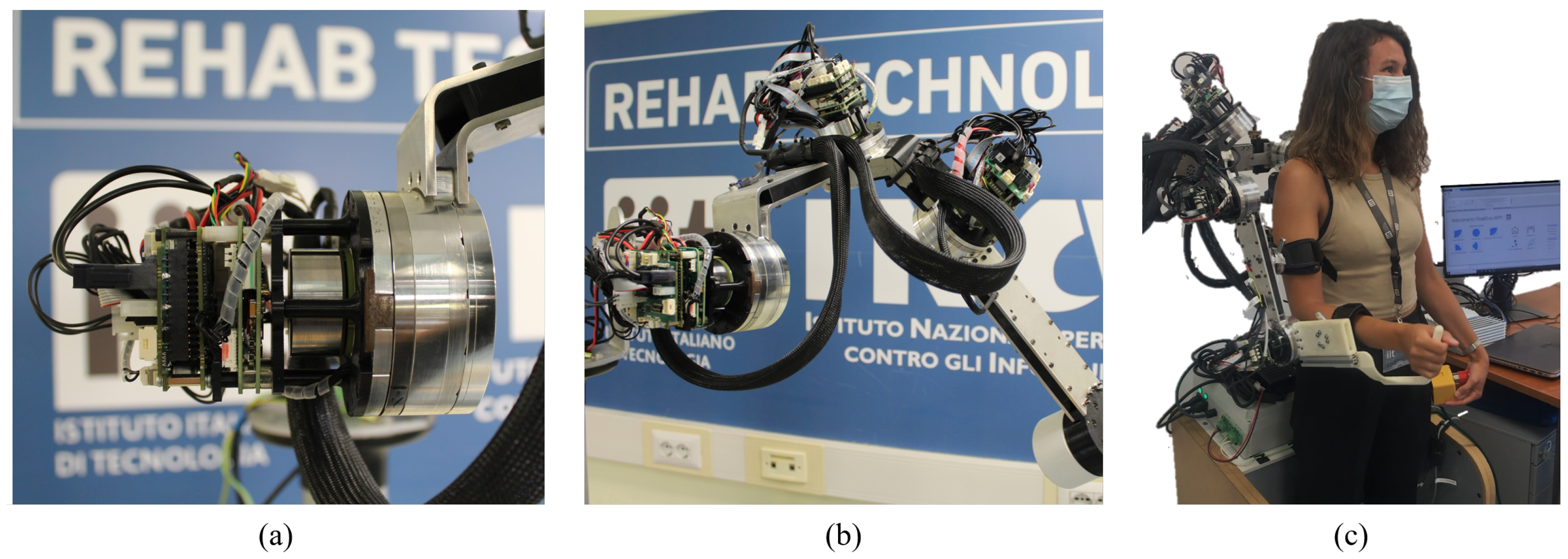
In the figure: (a) depicts the setup with EPOS boards for controlling the SEA joints and for the connection via CAN to the real-time target machine Speedgoat; (b) provides a close-up view of the spherical joint of the prototype used for real-time testing of developed control algorithms; (c) illustrates an example of the usability of the 6DoF prototype connected to Speedgoat, with control facilitated through a PC equipped with a GUI interface.
Figure 1.
In the figure: (a) depicts the setup with EPOS boards for controlling the SEA joints and for the connection via CAN to the real-time target machine Speedgoat; (b) provides a close-up view of the spherical joint of the prototype used for real-time testing of developed control algorithms; (c) illustrates an example of the usability of the 6DoF prototype connected to Speedgoat, with control facilitated through a PC equipped with a GUI interface.
Figure 2.
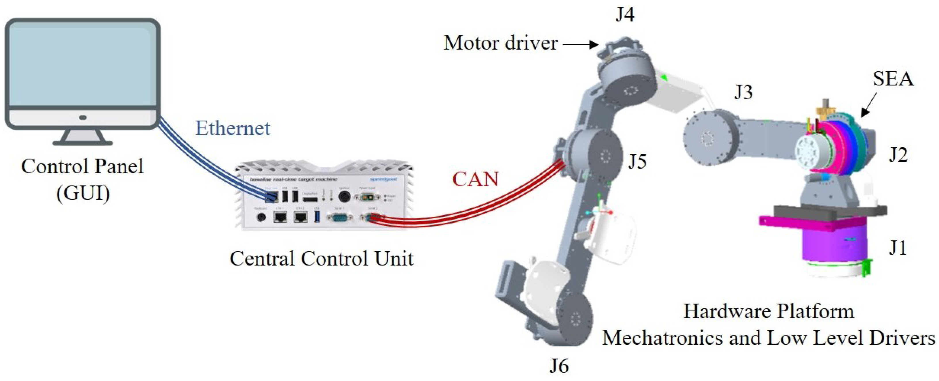
Hardware setup: EPOS motor controller and SEA sensors are connected via CAN to Speedgoat Baseline real time target machine. Speedgoat can communicate via ethernet with the host computer (Control Panel) receiving inputs from the GUI and providing feedback data about the running simulation.
Figure 2.
Hardware setup: EPOS motor controller and SEA sensors are connected via CAN to Speedgoat Baseline real time target machine. Speedgoat can communicate via ethernet with the host computer (Control Panel) receiving inputs from the GUI and providing feedback data about the running simulation.
Figure 3.
(a) Rigid body tree representing the kinematic chain of the 6-degree-of-freedom prototype. The Modified Denavit-Hartenberg (mDH) convention was followed for describing the kinematics. Each reference frame, representing a rotational degree of freedom, is associated with the dynamic properties of the body, including mass, center of mass coordinates, and the inertia tensor. (b) Graphical comparison between the torques estimated by the model and the ones measured by SEAs sensors. During the test the exoskeleton was moved in position control without a user or a load. In the plot are reported, for each joint, the torques estimated by the SEAs and the ones real-time computed from the model through the robotic toolbox.
Figure 4.
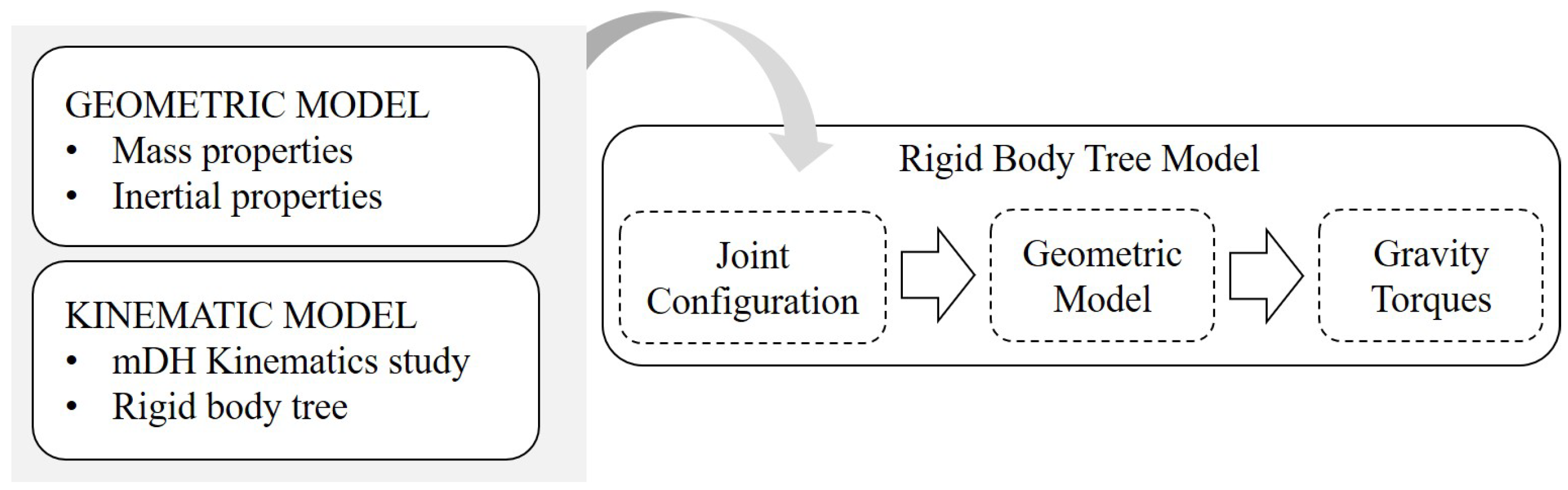
Workflow to develop the gravity torque estimation model: the dynamic model characterization for real-time gravity torque computation involves the utilization of various tools. In the CAD model of the prototype, the set of reference frames is redefined following the modified Denavit-Hartenberg (mDH) convention. Properties such as mass, center of mass, and inertia tensor for the different components of the device are then computed with respect to these reference frames. Using these dynamically derived properties, a rigid body tree model is constructed in MATLAB, adhering to the aforementioned mDH convention. This characterized model can be imported into the Gravity Torque function, which, in real-time, provides the joint torques necessary to maintain the robot at a specific configuration.
Figure 4.
Workflow to develop the gravity torque estimation model: the dynamic model characterization for real-time gravity torque computation involves the utilization of various tools. In the CAD model of the prototype, the set of reference frames is redefined following the modified Denavit-Hartenberg (mDH) convention. Properties such as mass, center of mass, and inertia tensor for the different components of the device are then computed with respect to these reference frames. Using these dynamically derived properties, a rigid body tree model is constructed in MATLAB, adhering to the aforementioned mDH convention. This characterized model can be imported into the Gravity Torque function, which, in real-time, provides the joint torques necessary to maintain the robot at a specific configuration.
Figure 5.
Top Layer of the Simulink control model. The model is built and then deployed on Speedgoat real time target machine. In this layer it is possible to identify four main blocks: CAN communication setup, readings of sensor data, processing of all the received data (this unit establishes the exoskeleton behaviour) and the output block that send over the CAN line the command signals.
Figure 6.
Graphical User Interface Welcome Panel: within this tab of the GUI, crafted using the App Designer MATLAB Tool, users can establish the preferred working mode of the exoskeleton. This includes initiating straightforward exercises under passive or compliant control (with selectable levels of assistance), configuring the number of repetitions, timing, and target positions for the exercises. Users can command the robot to return to the Home position or activate transparency mode. Additionally, functionalities such as learning and replaying are accessible. The GUI provides comprehensive information about the current phase of the exercise, the direction of the movement to be followed, the status of the machine (sleep, operative, fault), also, information about the joints position and the end-effector orientation angles are avaiable.
Figure 7.
The impedance control scheme employs the presented algorithm individually for each joint to compute the control signal. The reference target, representing the desired position, has to be reached by ensuring a certain compliance between the user and the device. The difference between the target and actual positions represents the delta displacement of a virtual spring, that multiplied by a virtual stiffness coefficient () provides the spring torsional torque. The actual joint speed introduces a viscous behavior, determined by the viscous coefficient (). The interaction torque, calculated as the difference between the estimated SEA torque and the gravity torque, serves as the feed−forward term. This ensures that the user can displace the exoskeleton in a compliant manner.
Figure 8.
Experimental results of impedance-based assistive control: three levels of assistance were tested by varying the stiffness-viscosity parameters of the impedance control (stiffness-viscosity couples are reported in
Table 2). In the figure, the black line indicates the joint reference target, while the blue, orange and yellow lines represent the results of three test at different assistance levels. The displayed oscillations are the consequences of human interaction with the robot. It is noticeable that lower assistance (high compliance, low stiffness) allows for greater interaction with the robot, enabling the user to deviate significantly from the target trajectory. Higher assistance (low compliance, high stiffness) leads to better adherence to the target trajectory, albeit restricting interaction with the device to some extent.
Table 1.
In the table, the maximum errors and root mean square errors (RMSE) and absolute errors () for the considered joints are computed by comparing the experimental measurements of SEA sensors with the output from the built-in gravity torque calculation function in the MATLAB Robotic Toolbox. The experiment conducted on the prototype involved the exoskeleton covering various zones within the workspace while operating in position control. This was carried out to validate the consistency of the SEA sensor readings with respect to the model characterized in MATLAB.
| Joint ID | RMSE [Nm] | [Nm] |
|---|
| J3 | 0.2877 | 0.8338 |
| J4 | 0.3101 | 0.8703 |
| J5 | 0.0649 | 0.3449 |
Table 2.
Pairs of stiffness and viscosity parameters ( and ) utilized in the impedance dynamic model to implement three different levels of assistance: decreasing corresponds to lower support and higher compliance.
Table 2.
Pairs of stiffness and viscosity parameters ( and ) utilized in the impedance dynamic model to implement three different levels of assistance: decreasing corresponds to lower support and higher compliance.
| Compliance | [Nm/rad] | [Nms/rad] |
|---|
| High | 30 | 1.2 |
| Medium | 10 | 1.2 |
| Low | 5.5 | 0.6 |
| Disclaimer/Publisher’s Note: The statements, opinions and data contained in all publications are solely those of the individual author(s) and contributor(s) and not of MDPI and/or the editor(s). MDPI and/or the editor(s) disclaim responsibility for any injury to people or property resulting from any ideas, methods, instructions or products referred to in the content. |
© 2024 by the authors. Licensee MDPI, Basel, Switzerland. This article is an open access article distributed under the terms and conditions of the Creative Commons Attribution (CC BY) license (https://creativecommons.org/licenses/by/4.0/).


