


SysML4GDPSim: A SysML Profile for Modeling Geometric Deviation Propagation in Multistage Manufacturing Systems Simulation


Abstract
1. Introduction
2. Modeling and Simulation of Product–Process–Resource Systems
2.1. PPR Systems Basis
2.2. Simulation System Modeling
- Generation of flow units based on a defined schedule or behavior: Objects with this functionality represent the beginning of the flow, and they have ports with which to send the data of the generated flow units.
- Processing flow units: Objects with this functionality have at least two ports with which to send and receive flow units. Moreover, a certain behavior can introduce changes in the data of the flow units. In the simulation of PPR systems, this function is mainly linked to the emulation of transforming resources (e.g., assembly or machining workstations) and logistic resources (stores or transportation resources).
- Destruction of flow units: Objects with this functionality represents the end point of the flow, where flow units are destroyed. These objects, generally named sinks, must have at least one port to receive flow units.
- Monitoring data and decisions making: Objects with this functionality have ports with which to receive data about key performance information. If they process data to make control decisions, they have ports with which to send data about these decisions. In a PPR systems simulation, these objects are linked to the control resources representation.
2.3. Representation and Calculation of Geometric Deviations
3. Proposed SysML4GDPSim Profile
3.1. Metamodel Description
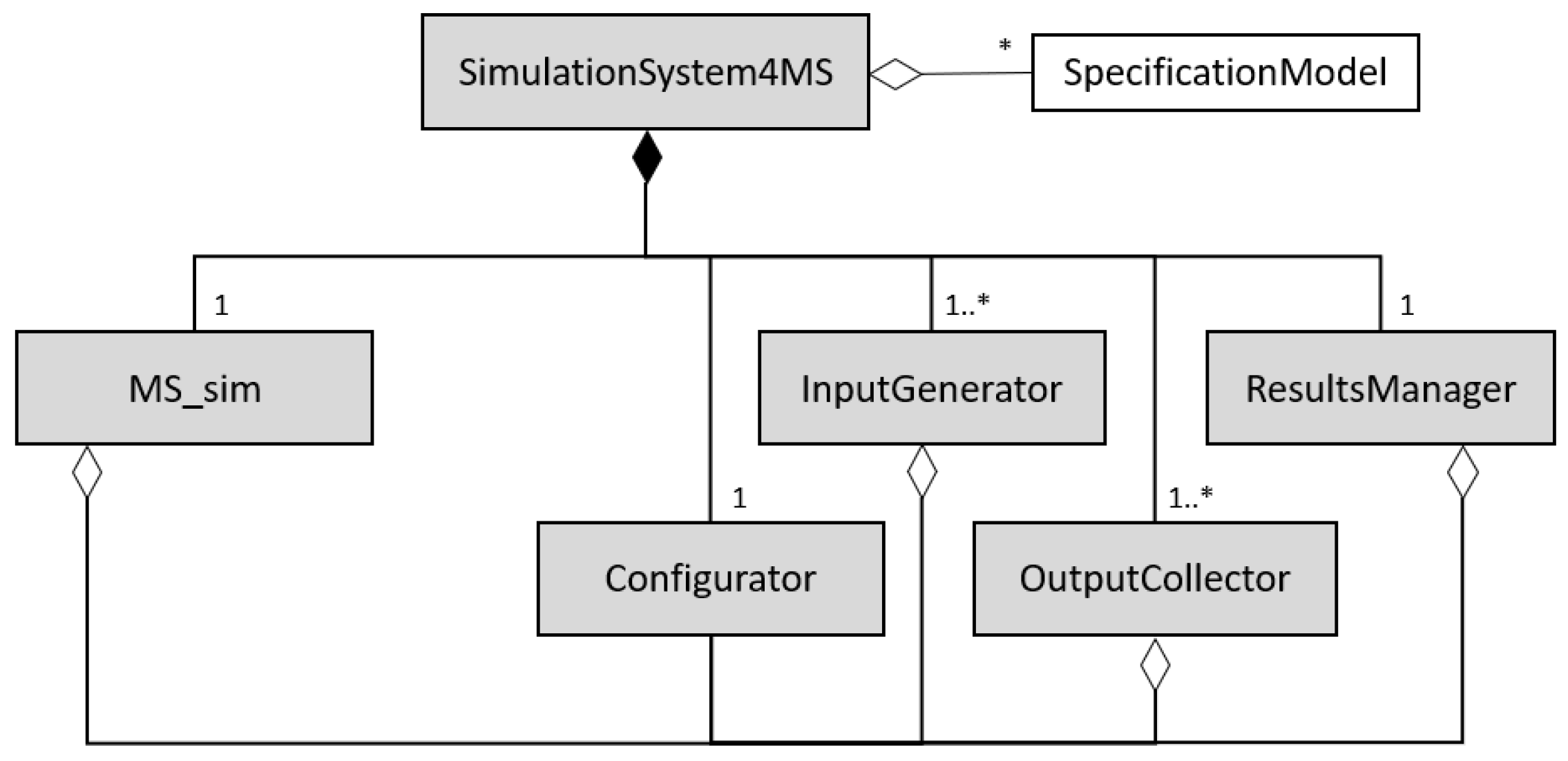
3.1.1. Simulation System Basic Structure
- Configurator identifies the component that groups all the characteristic parameters and offers them to the other components (MS_sim, InputGenerator, OutputCollector, etc.) through the reference relationships shown in Figure 1.
- InputGenerator represents components that create the FlowUnits, representing material supply (inputs for the MS_sim). An InputGenerator is the initial point of the data flow that represents the logistics flow.
- OutputCollector represents components that destroy FlowUnits; so, the OutputCollector is a sink or end point of the data flow that represents the materials flow.
- ResultsManager represents components that collect and process the information of simulation executions to compute the desired performance metrics.
3.1.2. The Manufacturing System in the Simulation System
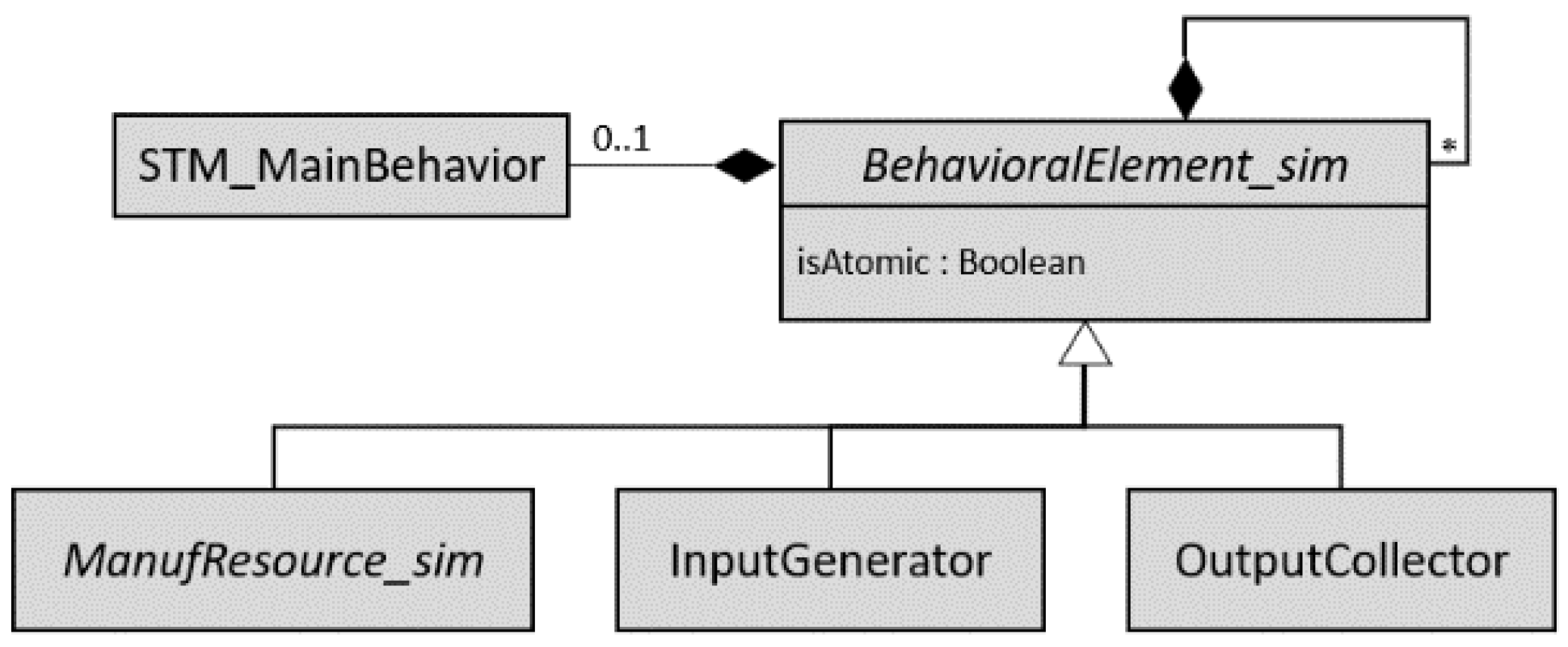
- ManufResource_sim (abstract) represents any resource of the simulated manufacturing system, i.e., both processor and control resources, ProcessingResource_sim and ControlResource_sim, respectively.
- ProcessingResource_sim is a specialization of the ManufResource_sim to emulate a resource through which batches of products flow, executing processes that modify some properties of the batches (e.g., location, flow times, etc.) or the contained products (e.g., its state or its geometric characteristics). A ProcessingResource_sim can be composed of other ManufResource_sim (i.e., both processing and control resources) and must have at least two FU_Ports to send and receive FlowUnits.
- TransformResource_sim is a specialization of the ProcessingResource_sim that emulates a transformer resource that modifies the properties of the FlowUnits; so, incoming FlowUnit type (input product) is different from the outgoing FlowUnit type (processed product).
- LogisticResource_sim is a specialization of the ProcessingResource_sim that emulates a logistical resource, participating in the materials flow without modifying FlowUnit properties so the type of incoming and outgoing FlowUnits is the same.
- ControlResource_sim is a specialization of the ManufResource_sim that emulates a control resource. ControlResource_sim does not participate in the logistics flow but exchanges data to support monitoring and decision making.
- FlowUnit represents a flowing unit, that is, a batch of products. Therefore, it will be composed of one or more Product_sim, which represents each material or product unit.
- DataPort represents a generic port as an interaction point to exchange data through connections that specify relationships between components of the simulation system.
- FU_Port is a specialization of the DataPort that supports the transfer of data on the simulated FlowUnits (product batches), supporting the logistics flow. As represented via a dependency relationship in Figure 2, this type of port must be typed by a FlowUnit.
- C_Port is a specialization of the DataPort that supports data transfer in the form of communication between resources to synchronize tasks and behaviors.
- Product_sim represents a simulated product unit characterized by properties that include the deviations for its key geometric characteristics. As a part of the FlowUnit, it supports geometric deviation propagation through the simulated manufacturing stages.
3.1.3. Behavior Modeling in the Simulation System
3.1.4. The Product in the Simulation System
3.1.5. Product–Resource Geometric Interaction in the Simulation System
3.2. SysML4GDPSim Profile
3.3. Developed Libraries
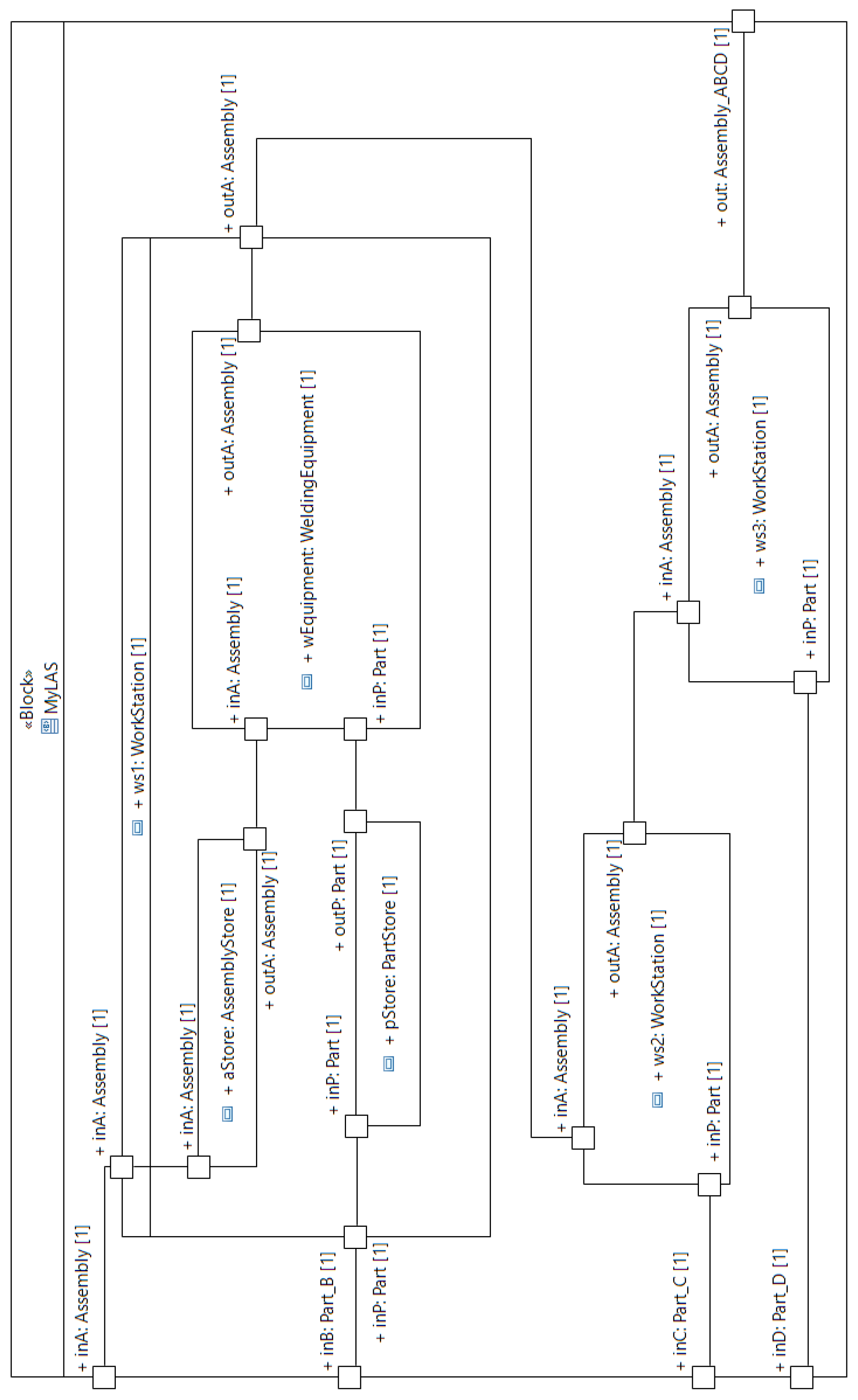
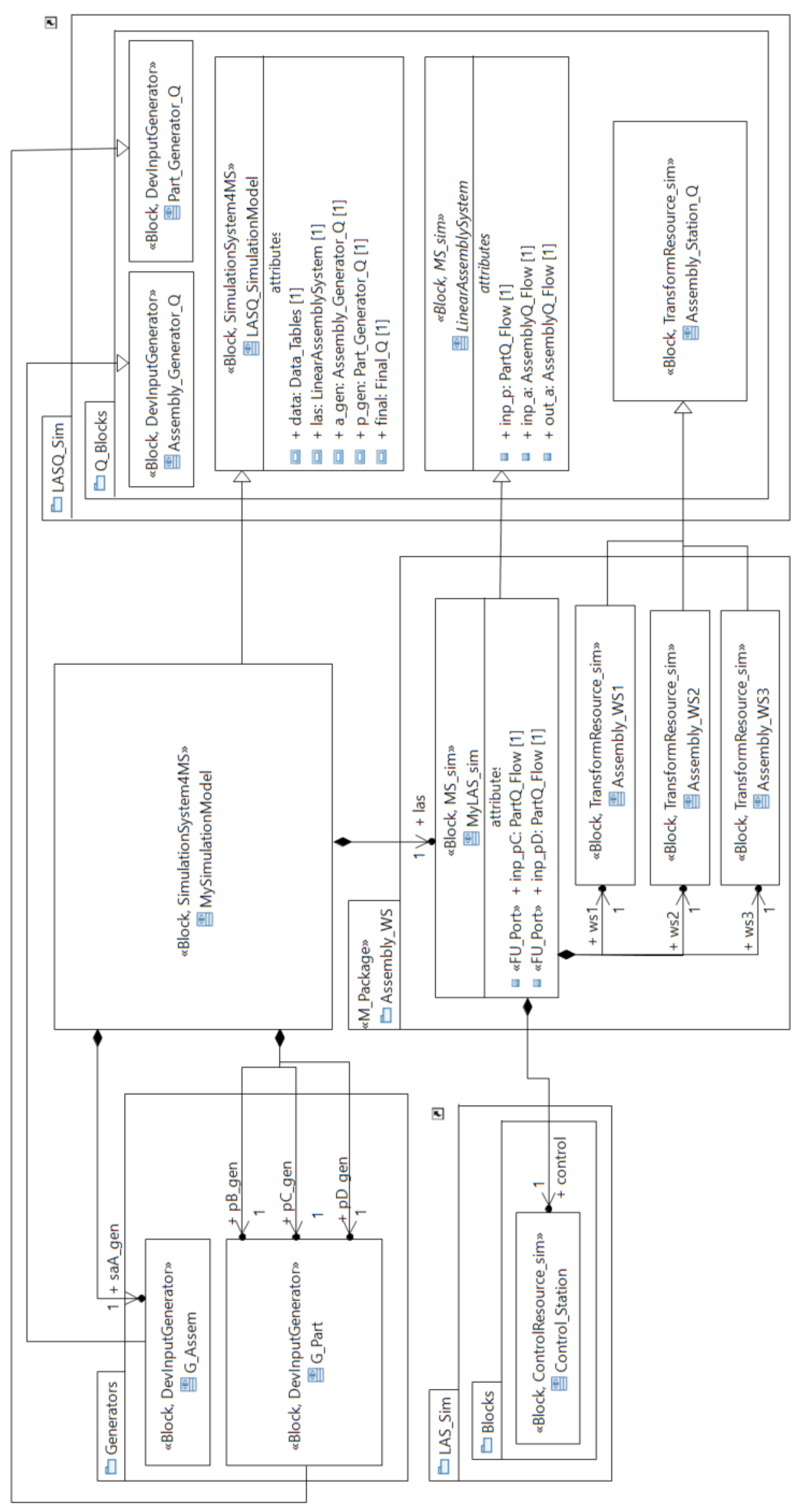
4. Case Study
4.1. Referent System Description
4.2. Simulation System Modeling
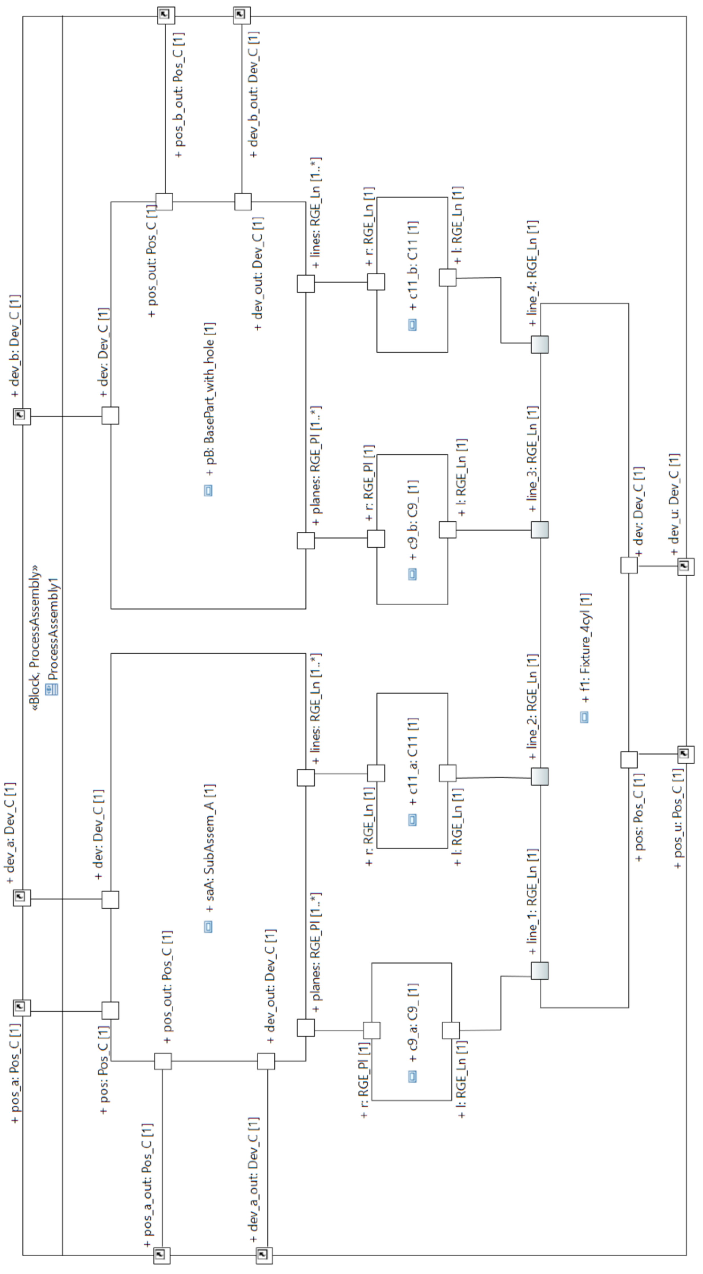
4.3. Geometric Artifact Modeling in the Simulation System
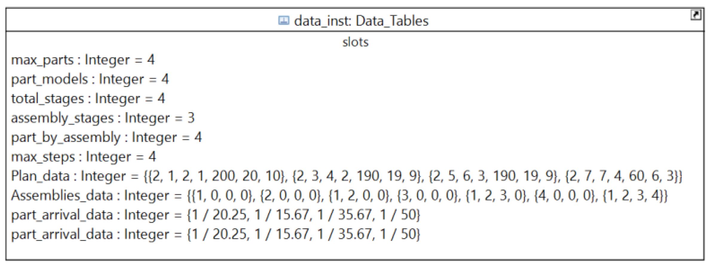
4.4. Experiment Definition and Model Transformation
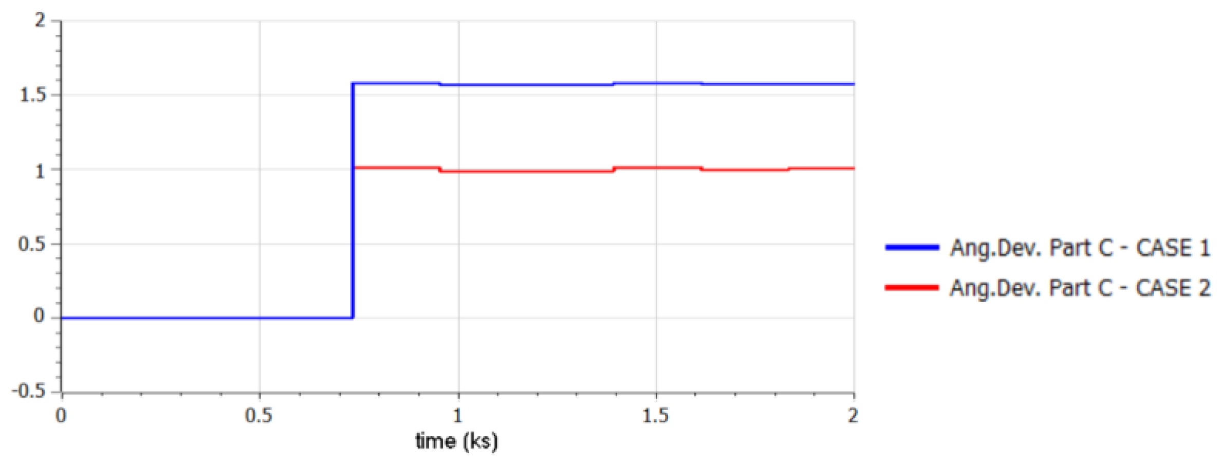
4.5. Experiment Results
5. Discussion
6. Conclusions and Future Work
Author Contributions
Funding
Institutional Review Board Statement
Informed Consent Statement
Data Availability Statement
Conflicts of Interest
Appendix A

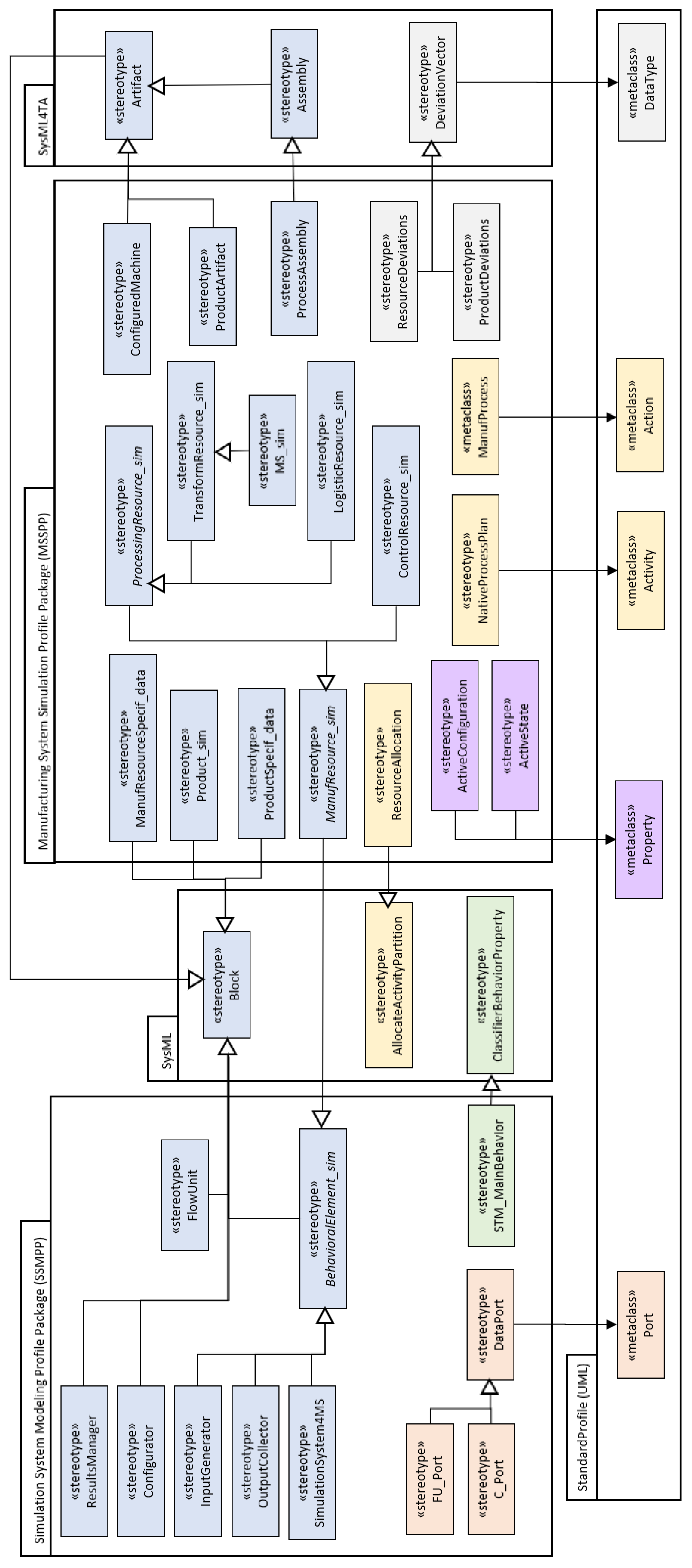
| Estereotype | Description |
|---|---|
| «BehavioralElement_sim» | Abstract stereotype that specializes the «Block» to represent any behavioral part of the simulation system (or the whole simulation system). A Boolean attribute (isAtomic) differentiates atomic and composite behavioral elements. Atomic behavioral elements have a «STM_MainBehavior» behavior (C1) and they cannot own behavioral parts (C2). Composite behavioral elements cannot have an explicitly defined behavior (C3) but they must own at least one behavioral part (C4). |
| «STM_MainBehavior» | «ClassifierBehaviorProperty» specialization to represent the behavior of an atomic «BehavioralElement_sim» Block, defined as a «StateMachine» (C5). |
| «SimulationSystem4MS» | «Block» representing the whole simulation system. A «SimulationSystem4MS» Block own a part typed by a «Configurator» block (C6), a part typed by a «ResultsManager» block (C7) a part typed by a «MS_sim» block (C8), at least one part typed by a «InputGenerator» block (C9), and at least one part typed by a «OutputCollector» block (C10). |
| «Configurator» | «Block» for data structuration and parameter definition in a simulation system. |
| «InputGenerator» | «BehavioralElement_sim» specialization to identify a block in which a flow unit starts, generating the unit flows with a periodicity defined in its behavior. An «InputGenerator» block must own at least one «FU_Port» port (C11). |
| «OutputCollector» | «BehavioralElement_sim» specialization to identify a block in which a Flow unit finishes. An «OutputCollector» block must own at least one «FU_Port» port (C12). |
| «ResultsManager» | «Block» defined to compute the performance measures from simulation data. A «ResultsManager» block must own at least one «DataPort» port (C13) to receive data from other simulation system parts. |
| «DataPort» | «Port» defined for the data exchange with other simulation system parts. |
| «FU_Port» | «DataPort» specialization to identify ports exchanging flow units. A «FU_Port» ports must be typed by a «FlowUnit» block (C14). |
| «C_Port» | «DataPort» specialization to identify ports defined for exchanging data related with the communication and processes synchronization. |
| «FlowUnit» | «Block» defined to represent a flow unit, representing a product batch. A «FlowUnit» block is composed by at least one part typed by «Product_sim» Block (C15). |
| Stereotype | Description |
|---|---|
| «ManufResource_sim » | Abstract stereotype that specializes the «BehavioralElement_sim» to identify any manufacturing resource. A block stereotyped by a «ManufResource_sim» specialization must have an aggregation relationship (reference) with a «ManufResourceSpecif_data» block (C16). |
| «ManufResourceSpecif_data» | «Block» defined to support specification data about a manufacturing resource type. A boolean property (isTransformer) identifies the specifications about transformer resources. A transformer resource specification (isTransformer = True) must have at least one part typed by a «ConfiguredMachine» block (C17). |
| «ConfiguredMachine» | «Artifact» specialization to define the TTRS_based representation of a specific configuration for a transformer resource. |
| «ProcessingResource_sim» | Abstract stereotype that specializes the «ManufResource_sim» to identify a processing resource definition, that is, a resource through which material units flow. A block stereotyped by a «ProcessingResource_sim» specialization must have at least two «FU_Port» ports (C18). |
| «TransformResource_sim» | «ProcessingResource_sim» specialization to represent transformer resources where product characteristics are modified. A «TransformResource_sim» block must own an «ActiveConfiguration» property (C19) and at least one part typed by «ResourceDeviations» data type (C20), and its two «FU_Port» ports must be typed by different blocks (C21). |
| «MS_sim» | «TransformResource_sim» specialization to identify the block that emulates the whole manufacturing system. |
| «ActiveConfiguration» | «Property» owned by a «TransformResource_sim» block (C22) identifying the current configuration of a transformer resource. |
| «ResourceDeviations» | «DeviationVector» specialization to define deviation values for the key geometric characteristics in a resource artefactual representation. |
| «LogisticResource_sim» | «ProcessingResource_sim» specialization to represent logistic. A «LogisticResource_sim» block cannot own any party typed by a «TransformResource_sim» block (C23), and its two «FU_Port» ports must be typed by the same block (C24). |
| «ControlResource_sim» | «ManufResource_sim» specialization to represent a control resource, that is, a resource that supports the monitoring, control and decision-making functionality. A «ControlResource_sim» block cannot have any «FU_Port» port (C25), but it must have at least one «C_Port» or «DataPort» port (C26). |
| «Product_sim» | «Block» defined to support data about product units. A «Product_sim» block have an aggregation relationship (reference) with a «ProductSpecif_data» block (C27) and an «ActiveState» property (C28). |
| «ProductDeviations» | «DeviationVector» specialization to define deviation values for the key geometric characteristics in a product artefactual representation. |
| «ActiveState» | «Property» of a «Product_sim» block (C29) used to define the current product state. |
| «ProductSpecif_data» | «Block» defined to support specification data about a product type considered in the simulation system. A «ProductSpecif_data» block must include a behavior defined by a «NativeProcessPlan» activity (C30) and at least two parts typed by different «ProductArtifact» blocks (C31) to support the artefactual representations of the product at different manufacturing states. |
| «ProductArtifact» | «Artifact» specialization to define the TTRS_based representation of a specific state for a product type. |
| «NativeProcessPlan» | «Activity» defined to stablish the manufacturing stages of a product and the resources where they are executed. All the activities included in a «NativeProcessPlan» activity must be stereotyped as «ManufProcess» (C32) and they must be contained in a «ResourceAllocation» allocate activity partition (C33). |
| «ManufProcess» | «Action» owned by a «NativeProcessPlan» activity (C34) representing a manufacturing stage. A Boolean attribute (isAtomic) identifies the atomic processes, in this case, the subphases. |
| «ResourceAllocation» | Specialization of the «AllocateActivityPartition» to assign particular resources to each «ManufProcess». It must be defined in a «NativeProcessPlan» Activity (C34). Every contained action must be stereotyped as «ManufProcess». |
| «ProcessAssembly» | «Assembly» specialization to define the TTRS_based representation of a process assembly, so a «ProcessAssembly» block has at least one reference to a «ProductArtifact» block and another reference to a «ConfiguredMachine» block. |
Appendix B
| Rule | OCL Expression |
|---|---|
| C2 | if self.isAtomic=true then self.base_Class.allAttributes()->select(a|a.type.oclIsKindOf(UML::Class)). type.oclAsType(UML::Class).getAppliedStereotypes().allParents()->select(b|b.name = ‘BehavioralElement_sim’)->isEmpty() endif |
| C5 | self.oclIsKindOf(UML::StateMachine) |
| C11 | self.base_Class.allAttributes()->select(a|a.type.oclIsKindOf(UML::Port)). getAppliedStereotypes()-> select(b|b.name = ‘FU_Port’).size() = 1 |
References
- Colledani, M.; Tolio, T.; Fischer, A.; Iung, B.; Lanza, G.; Schmitt, R.; Váncza, J. Design and management of manufacturing systems for production quality. CIRP Ann. 2014, 63, 773–796. [Google Scholar] [CrossRef]
- Psarommatis, F.; May, G.; Dreyfus, P.A.; Kiritsis, D. Zero-defect manufacturing: State-of-the-art review, shortcomings and future directions in research. Int. J. Prod. Res. 2020, 58, 1–18. [Google Scholar] [CrossRef]
- Zhang, L.; Zhou, L.; Ren, L.; Laili, Y. Modeling and simulation in intelligent manufacturing. Comput. Ind. 2019, 112, 103123. [Google Scholar] [CrossRef]
- Henderson, K.; Salado, A. Value and benefits of model-based systems engineering (MBSE): Evidence from the literature. Syst. Eng. 2021, 24, 51–66. [Google Scholar] [CrossRef]
- Ferreira, W.D.; Armellini, F.; Santa-Eulalia, L.A. Simulation in industry 4.0: A state-of-the-art review. Comput. Ind. Eng. 2020, 149, 106868. [Google Scholar] [CrossRef]
- Vještica, M.; Dimitrieski, V.; Pisarić, M.; Kordić, S.; Ristić, S.; Luković, I. An application of a DSML in Industry 4.0 production processes. In Proceedings of the IFIP International Conference on Advances in Production Management Systems (APMS), Novi Sad, Serbia, 30 August 2020. [Google Scholar]
- OMG Systems Modeling Language (SysML), v. 1.6. Available online: https://sysml.org/.res/docs/specs/OMGSysML-v1.6-19-11-01.pdf (accessed on 17 January 2024).
- OMG Object Constraint Language (OCL), v. 2.4. Available online: https://www.omg.org/spec/OCL/ (accessed on 13 January 2023).
- Gauthier, J.-M.; Bouquet, F.; Hammad, A.; Peureux, F. Tooled process for early validation of SysML models using Modelica simulation. In Proceedings of the Fundamentals of Software Engineering (FSEN 2015), Tehran, Iran, 22–24 April 2015. [Google Scholar]
- OMG, SysML-Modelica Transformation, Version 1.0, Object Management Group. Available online: https://www.omg.org/spec/SyM/1.0/PDF (accessed on 6 February 2024).
- Benavent-Nácher, S. Modelado y Simulación Híbrida de Sistemas de Fabricación Multietapa Orientado a la Evaluación de la Calidad Geométrica y la Productividad. Ph.D. Thesis, Universitat Jaume I, Castelló de la Plana, Spain, 2024. [Google Scholar]
- Höpfner, G.; Jacobs, G.; Zerwas, T.; Drave, I.; Berroth, J.; Guist, C.; Rumpe, B.; Kohl, J. Model-based design workflows for cyber-physical systems applied to an electric-mechanical coolant pump. In Proceedings of the 19th Drive Train Technology Conference (ATK 2021), Aachen, Germany, 9–11 March 2021. [Google Scholar]
- Wagner, H.; Zuccaro, C. Collaboration between system architect and simulation expert. In Proceedings of the IEEE International Symposium on Systems Engineering, Vienna, Austria, 24–26 October 2022. [Google Scholar]
- Benavent-Nácher, S.; Rosado, P.; Romero, F. Multidomain simulation model for analysis of geometric variation and productivity in multi-stage assembly systems. Appl. Sci. 2020, 10, 6606. [Google Scholar] [CrossRef]
- Lefeber, E.; Rooda, J.E. Modeling and analysis of manufacturing systems. In Handbook of Dynamic System Modeling, 1st ed.; Chapman and Hall/CRC: New York, NY, USA, 2007. [Google Scholar]
- Clément, A. The TTRSs: 13 Constraints for dimensioning and tolerancing. In Geometric Design Tolerancing: Theories, Standards and Applications; Springer: Boston, MA, USA, 1998; pp. 122–131. [Google Scholar]
- INCOSE. Systems Engineering Handbook: A Guide for Systems Life Cycle Processes and Activities, 4th ed.; John Wiley & Sons: Hoboken, NY, USA, 2015. [Google Scholar]
- Dictionary by Merriam Webster. Available online: https://www.merriam-webster.com/dictionary/supersystem (accessed on 6 February 2024).
- Gedell, S.; Claesson, A.; Johannesson, H. Integrated product and production model—Issues on completeness, consistency and compatibility. In Proceedings of the 18th International Conference on Engineering Design (ICED 11), Lyngby/Copenhagen, Denmark, 15–19 August 2011. [Google Scholar]
- Kathrein, L.; Meixner, K.; Winkler, D.; Lüder, A.; Biffl, S. A meta-Model for representing consistency as extension to the formal process description. In Proceedings of the 24th IEEE International Conference on Emerging Technologies and Factory Automation (ETFA), Zaragoza, Spain, 10–13 September 2019. [Google Scholar]
- Bifll, S.; Lüder, A.; Gerhard, D. Multidisciplinary Enginering for Ciber-Physical Production System; Biffl, S., Lüder, A., Gerhard, D., Eds.; Springer: Cham, Switzerland, 2017. [Google Scholar]
- Michaelis, M.T. Function and process modeling for integrated product and manufacturing system platforms. J. Manuf. Syst. 2015, 36, 203–215. [Google Scholar] [CrossRef]
- Souilah, M.; Tahan, A.; Abacha, N. A small displacement torsor model to evaluate machining accuracy in the presence of locating and machine geometric errors. In Proceedings of the Canadian Society for Mechanical Engineering International Congress 2021, Charlottetown, PE, Canada, 27–30 June 2021. [Google Scholar]
- Bruscas-Bellido, G. Modelo Basado en Elementos Característicos Para la Planificación Supervisora de la Inspección. Ph.D. Thesis, Universitat Jaume I, Castelló de la Plana, Spain, 2015. [Google Scholar]
- Law, A.M. Simulation Modeling and Analysis, 5th ed.; Mc Graw Hill: Tucson, AZ, USA, 2015. [Google Scholar]
- Kim, T.G.; Zeigler, B.P. The DEVS formalism: Hierarchical, modular systems specification in an object-oriented framework. In Proceedings of the 1987 Winter Simulation Conference, Atlanta, GA, USA, 14–16 December 1987. [Google Scholar]
- Tian, A.; Liu, S.; Chen, K.; Mo, W.; Jin, S. Spatial expression of assembly geometric errors for multi-axis machine tool based on kinematic Jacobian-torsor model. Chin. J. Mech. Eng. 2023, 36, 44. [Google Scholar] [CrossRef]
- Mu, X.; Yuan, B.; Wang, Y.; Sun, W.; Liu, C.; Sun, Q. Novel application of mapping method from small displacement torsor to tolerance: Error optimization design of assembly parts. J. Eng. Manuf. 2022, 236, 955–967. [Google Scholar] [CrossRef]
- Wang, H.; Lin, Y.; Yan, C. T-Maps-based tolerance analysis of composites assembly involving compensation strategies. ASME J. Comput. Inf. Sci. Eng. 2022, 22, 041007. [Google Scholar] [CrossRef]
- Jiang, Q.; Ou, Y.; Zou, Y.; Zhou, C.-G.; Huang, S.; Qian, C.-Q. Analysis and optimization of tolerance design for an internal thread grinder. Int. J. Adv. Manuf. Technol. 2023, 125, 5369–5383. [Google Scholar] [CrossRef]
- Umaras, E. A New Method of Rigid Assemblies Stochastic 3D Tolerance Analysis Including Thermal Performance. Ph.D. Thesis, Universidade de São Paulo, Sao Paulo, Brazil, 2022. [Google Scholar]
- Monica, F.D.; Patalano, S.; Choley, J.; Mhenni, F.; Gerbino, S. A hierarchical set of SysML model-based objects for tolerance specification. In Proceedings of the IEEE International Symposium on Systems Engineering, Edinburgh, UK, 3–5 October 2016. [Google Scholar]
- Benavent-Nácher, S.; Rosado Castellano, P.; Romero Subirón, F.; Abellán-Nebot, J.V. SYSML4TA: A SysML profile for consistent tolerance analysis in a manufacturing system case application. Appl. Sci. 2023, 13, 3794. [Google Scholar] [CrossRef]
- Aguilella-Antolí, D.; Rosado-Castellano, P.; Benavent-Nácher, S. A Modelica library to simulate geometrical and dimensional deviations in process assemblies. In Proceedings of the 10th Manufacturing Engineering Society International Conference, Sevilla, Spain, 28–30 June 2023. [Google Scholar]
- ASME. Dimensioning and Tolerancing. Y14.5; American Society of Mechanical Engineers: New York, NY, USA, 2019. [Google Scholar]
- Mourtzis, D. Simulation in the design and operation of manufacturing systems: State of the art and new trends. Int. J. Prod. Res. 2020, 58, 1927–1949. [Google Scholar] [CrossRef]
- Hallmann, M.; Schleich, B.; Wartzack, S. From tolerance allocation to tolerance-cost optimization: A comprehensive literature review. Int. J. Adv. Manuf. Technol. 2020, 107, 4859–4912. [Google Scholar] [CrossRef]
- Zhou, S.; Huang, Q.; Shi, J. State space modelling of dimensional variation propagation in multistage machining process using differential motion vectors. Trans. Robot. Autom. 2003, 19, 296–309. [Google Scholar] [CrossRef]
- Abellan-Nebot, J.V.; Liu, J.; Romero, F. Design of multi-station manufacturing processes by integrating the stream-of-variation model and shop-floor data. J. Manuf. Syst. 2011, 30, 70–82. [Google Scholar] [CrossRef]
- Delchamps, D.F. State Space and Input-Output Linear Systems; Springer: New York, NY, USA, 2011. [Google Scholar]
- Barbedienne, R.; Penas, O.; Choley, J.Y.; Rivière, A.; Warniez, A.; Della Monica, F. Introduction of geometrical constraints modeling in SysML for mechatronic design. In Proceedings of the 10th Europe-Asia Congress on Mechatronics, Tokyo, Japan, 27–29 November 2014. [Google Scholar]
- Kernschmidt, K. Interdisciplinary Structural Modeling of Mechatronic Production Systems Using SysML4Mechatronics. Ph.D. Thesis, Technische Universitat Munchen, Munchen, Germany, 2019. [Google Scholar]
- Nachmann, I.; Rumpe, B.; Wortmann, A.; Berroth, J.; Hoepfner, G.; Jacobs, G.; Spuetz, K.; Zerwas, T.; Guist, C.; Kohl, J. Modeling mechanical functional architectures in SysML. In Proceedings of the 23rd ACM/IEEE International Conference on Model Driven Engineering Languages and Systems, Virtual Event, Canada, 16–23 October 2020. [Google Scholar]


| Variable | Results |
|---|---|
| Finished products | 203 |
| Throughput (Prod./h) | 14.61 |
| Finished products meeting specifications | 164 |
| Throughput with products meeting specifications (Prod./h) | 11.81 |
Disclaimer/Publisher’s Note: The statements, opinions and data contained in all publications are solely those of the individual author(s) and contributor(s) and not of MDPI and/or the editor(s). MDPI and/or the editor(s) disclaim responsibility for any injury to people or property resulting from any ideas, methods, instructions or products referred to in the content. |
© 2024 by the authors. Licensee MDPI, Basel, Switzerland. This article is an open access article distributed under the terms and conditions of the Creative Commons Attribution (CC BY) license (https://creativecommons.org/licenses/by/4.0/).
Share and Cite
Benavent-Nácher, S.; Rosado Castellano, P.; Romero Subirón, F. SysML4GDPSim: A SysML Profile for Modeling Geometric Deviation Propagation in Multistage Manufacturing Systems Simulation. Appl. Sci. 2024, 14, 1830. https://doi.org/10.3390/app14051830
Benavent-Nácher S, Rosado Castellano P, Romero Subirón F. SysML4GDPSim: A SysML Profile for Modeling Geometric Deviation Propagation in Multistage Manufacturing Systems Simulation. Applied Sciences. 2024; 14(5):1830. https://doi.org/10.3390/app14051830
Chicago/Turabian StyleBenavent-Nácher, Sergio, Pedro Rosado Castellano, and Fernando Romero Subirón. 2024. "SysML4GDPSim: A SysML Profile for Modeling Geometric Deviation Propagation in Multistage Manufacturing Systems Simulation" Applied Sciences 14, no. 5: 1830. https://doi.org/10.3390/app14051830
APA StyleBenavent-Nácher, S., Rosado Castellano, P., & Romero Subirón, F. (2024). SysML4GDPSim: A SysML Profile for Modeling Geometric Deviation Propagation in Multistage Manufacturing Systems Simulation. Applied Sciences, 14(5), 1830. https://doi.org/10.3390/app14051830