Article

Optimization Design of Double Wishbone Front Suspension Parameters for Large Mining Dump Truck and Analysis of Ride Comfort

1
College of Mechanical Engineering, Inner Mongolia University of Science and Technology, Baotou 014010, China
2
Inner Mongolia Key Laboratory of Intelligent Diagnosis and Control of Mechatronic System, Inner Mongolia University of Science and Technology, Baotou 014010, China
3
Inner Mongolia North Hauler Joint Stock Co., Ltd., Baotou 014000, China
*
Author to whom correspondence should be addressed.
Appl. Sci. 2024, 14(5), 1812; https://doi.org/10.3390/app14051812
Submission received: 22 January 2024 / Revised: 20 February 2024 / Accepted: 20 February 2024 / Published: 22 February 2024

Abstract

:
With the advancement of technology, mining trucks are gradually becoming larger, imposing higher performance requirements on the front suspension. There is a need to transform the original integral non-independent front axle of mining dump trucks with a payload exceeding 300 tons into an independent front suspension with a double-wishbone suspension. The changing of the front suspension is bound to have an impact on the overall vehicle’s handling stability and ride comfort. Therefore, the following research is conducted to investigate and analyze these effects. Firstly, the paper proposes a method for optimizing the parameters of the double-wishbone front suspension. The double-wishbone front suspension is modeled, and a comparison with a kinematic model is conducted to validate the accuracy of the model. Secondly, unreasonable hardpoint parameters are optimized. Thirdly, a dynamic model of the entire vehicle is established based on the optimized parameters, and an analysis of handling stability and ride comfort for the entire vehicle is performed. Finally, simulation results are compared and analyzed against experimental data. The results indicate that the optimized positioning parameters not only effectively enhance the suspension performance of the mining dump truck but also meet the requirements for handling stability and smoothness. The overall smoothness of the vehicle is significantly improved after the modification. This study not only holds significant engineering value in reducing vibrations in dump trucks and enhancing driver comfort, but also provides theoretical support for subsequent research and development in the industry.

1. Introduction

The development of mining dump trucks is hindered by high technical difficulty, the need for substantial capital investment, and a lengthy research and development cycle, resulting in a scarcity of relevant studies. Additionally, due to the wide dimensions, heavy payload, and harsh working conditions of mining dump trucks, significant vibrations are easily generated, affecting both handling stability and ride comfort [1]. Suspension systems play a vital role as essential components in vehicles, primarily being tasked with dampening vibrations arising from road roughness. They are also responsible for transmitting forces to the vehicle body, thereby influencing ride comfort, handling, stability, and overall safety performance [2,3,4].
Currently, mining dump trucks mainly utilize integral front axles as their front suspension. However, due to the integral front axle being a non-independent suspension, the front wheels interfere with each other during operation, resulting in relatively lower handling stability and smoothness of the entire vehicle. Moreover, as the overall vehicle weight of dump trucks continues to increase, there is an urgent need to adopt a new type of independent suspension to meet design goals. The candle-type front suspension is relatively mature in the field of medium and small mining dump trucks. The structure of mining vehicles equipped with candle-type independent front suspension is more compact, allowing the engine’s assembly components to be easily adjusted to a lower position, thus lowering the vehicle’s center of gravity. However, since the kingpin is fixed on the frame, the front wheel track may be affected by the up-and-down movement of the piston rod of the oil-gas suspension, resulting in lateral tire slip, further increasing tire wear. Additionally, the contact surface between the rod and cylinder of this suspension often generates significant lateral forces, greatly reducing the service life of the front suspension components due to the significant effects of lateral forces. The double-wishbone front suspension, on the other hand, does not have these drawbacks. These wishbones can absorb lateral forces, enhancing the vehicle’s resistance to tilting during steering; the kingpin only needs to bear the weight of the vehicle. Additionally, the structural design of the double-wishbone front suspension allows the vehicle to correct its camber angle during operation, to some extent reducing the lateral slip of the wheels and decreasing tire wear. Furthermore, it can adjust the position of the wishbones to adapt to the road surface, enabling the tires to have a larger contact area with the ground, thereby improving ground adhesion performance. Therefore, this paper proposes to transform the integral front axle into a double-wishbone independent front suspension and conduct research on it.
Amir Afkar [5] utilized ADAMS software to model and optimize an off-road vehicle in 2012. By conducting simulation analyses on various subsystems of the entire vehicle, potential design issues were identified, leading to improvements in the overall handling stability and smoothness. The outcomes of this research not only serve as a reference for the design and optimization of off-road vehicles, but also offer valuable insights and experiences applicable to the design of other vehicle types. In 2014, Kang Yiting [6] and other scholars conducted a study on the ride comfort of a 190-ton mining truck, employing various front suspension systems, including double-wishbone independent suspension and candlestick suspension. The researchers utilized Maple Sim to model and simulate the different front suspension systems under various road conditions. Through comparative analysis of the wheel alignment parameters with changing wheel bounce, they ultimately concluded that the double-wishbone independent suspension and multi-link independent suspension exhibited superior kinematic characteristics. Global mining truck manufacturers have also actively pursued technological innovations, exploring various approaches to innovate and enhance the structural design of mining trucks to improve overall performance. The Liebherr Group, in its 600-ton mining truck, employs a double-wishbone front suspension and a multi-link rear suspension, significantly reducing the lateral forces experienced by the wheels. Various configurations are implemented to minimize tire wear, maximizing the lifespan of the tires to the greatest extent possible [7]. In recent years, scholars in the field have gradually shifted their research focus towards enhancing the handling stability and ride comfort of mining dump trucks. Wang et al. [8,9] applied the quasi-zero stiffness isolator to the vibration isolation of the car, established a vehicle-seat-human coupling dynamics model, and studied the impact excitation and random excitation of the model. The dynamic characteristics of the vehicle have effectively improved the vibration comfort of the vehicle. To meet the increasingly higher demands for vibration comfort, active vibration control [10] technology has begun to be applied in vehicle damping, including both active and semi-active suspension technologies. Xiao et al. [11] transformed the base between the cabin floor and the seat into a particle damper, establishing a discrete element model for the damper to analyze and determine the optimal solution. They successfully reduced the vibrations in the mining dump truck’s cabin, thereby improving vibration comfort. Zou et al. [12] proposed a hydraulic interconnected suspension system based on energy regenerative shock absorbers to simultaneously enhance ride comfort, traction capability, and energy recovery potential. They established a seven-degree-of-freedom whole-vehicle suspension model for modeling and driving analysis. The results indicate that the new suspension system can attenuate vibrations, maintaining excellent ride comfort. Kihan Kwon [13] improved vehicle ride comfort and stability by optimizing the parameters of the oil and gas suspension. Subsequently, they built a comprehensive vehicle model to analyze the vehicle’s performance. Proper suspension design is more crucial for heavy-duty vehicles than for passenger cars due to their different dynamic behaviors [14,15]. Due to the interdependencies among various performance parameters of suspension systems, to avoid situations where improving one performance aspect leads to a decline in others, multi-objective optimization should be conducted to determine design solutions that simultaneously optimize all performance indicators [16,17,18]. Additionally, accurate analysis of heavy-duty vehicle behavior, considering pitch and roll effects, requires a comprehensive vehicle model to achieve optimal suspension design.
In recent years, scholars in the field have primarily focused on active vibration control technology, optimization of oil and gas springs, and cabin damping for the suspension system of mining dump trucks. This research aims to enhance the handling stability and ride comfort of dump trucks. However, there is relatively limited research on the application of double-wishbone suspension in mining dump trucks; therefore, it is essential to modify, validate, analyze, and optimize the front suspension of a 300-ton-class mining dump truck. Subsequently, conducting a comprehensive comparison with actual data for the entire vehicle becomes necessary. This paper focuses on optimizing specific spatial parameters of the double-wishbone front suspension to enhance suspension performance, with noticeable effects. The modified vehicle’s ride comfort is then compared with experimental data to validate the improvement in ride comfort. The main content is as follows: Section 2 optimizes the parameters of the double-wishbone front suspension and conducts simulations; Section 3 establishes a whole vehicle model for verification of handling stability and ride comfort; Section 4 analyzes and compares the optimized results with empirical results; Section 5 provides a summary and discussion.

2. The Optimization Design of Parameters and Parallel Wheel Travel Simulation

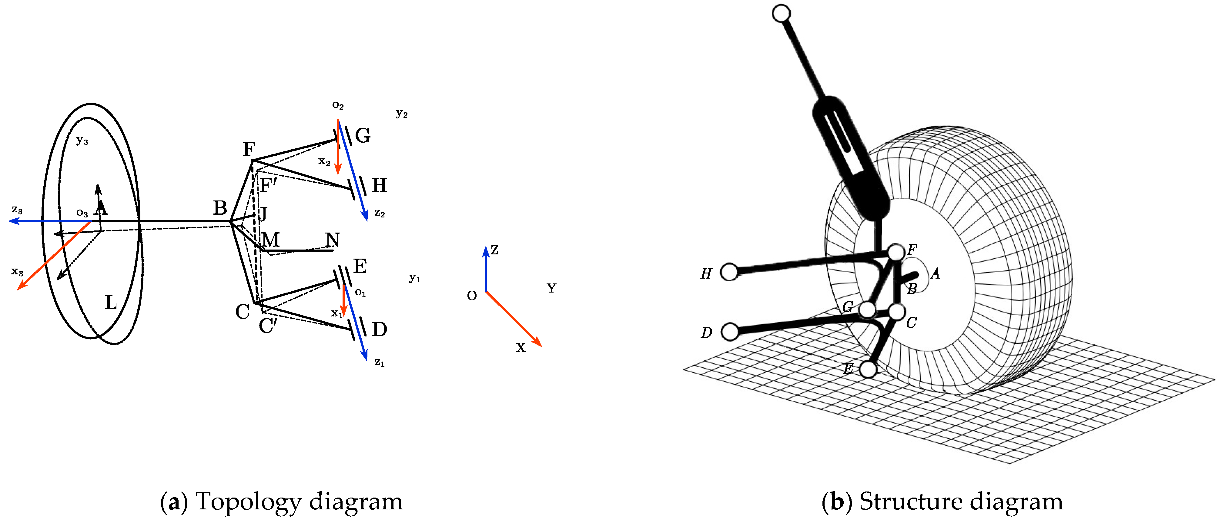
Figure 1a depicts the spatial topology diagram of a double-wishbone front suspension. In this diagram, CDE and FGH constitute the upper and lower control arms, respectively, rotating around the virtual axes Co1 and Fo2 at points o1 and o2. F and C are the connection points (outer points of the upper and lower arms) to the wheel-steering knuckle using ball joints. Point B represents the power input half-shaft end, MN denotes the steering tie rod, A is the center of the wheel, and L is the point of wheel contact with the ground. The origin o serves as the coordinate origin for the entire vehicle, and local coordinate systems are established at o1, o2, and the wheel center point A. Figure 1b provides a schematic diagram of a double-wishbone front suspension structure.
The quality of the suspension guidance structural performance is determined by the ability of the wheel and suspension parameters to remain within reasonable limits during the normal vertical travel of the wheel. The wheel and suspension characteristics of the suspension system shown in the figure can be calculated using the following formula [19,20]:
Defining the kingpin inclination angle as positive when the kingpin is inclined inward. When the kingpin is inclined backward, the caster angle is defined as positive. When the wheel is tilted outward, the camber angle is defined as positive. When the front toe is inclined towards the vehicle’s neutral plane, the toe angle is defined as positive.
During the vertical travel of the suspension, it is required to minimize the wheel’s camber angle, while keeping the lateral slip and toe angle as constant or changing it as minimally as possible. Simultaneously, when determining the suspension hard points’ positions, it is essential to ensure other suspension characteristics, such as roll height.
The lateral slip at the wheel center A  Δ S lat :
Δ S lat   = A y m a x A y m i n
Camber angle ψ :
ψ = a r c t a n L y A y L z A z
Toe angle θ :
θ = a r c t a n A x B x A y B y
Set z ˆ 1 and z ˆ 2 as the unit vectors along the Z axes in the coordinate system o 1 and o 2 . When the wheel undergoes vertical motion, the upper and lower arms rotate about the direction vectors z ˆ 1 and z ˆ 2 by angles α and β . As a result, points C and F rotate to C’ and F’.
Applying the finite rotation tensor, we get:
o 1 C = Z z ˆ 1 α o 1 C
o 2 F = Z z ˆ 2 β o 2 F
in which:
Z z ˆ 1 α = c o s α I + ( 1 c o s α ) z ˆ 1 z ˆ 1 + s i n α Z ˆ 1 Z z ˆ 2 β = c o s β I + ( 1 c o s β ) z ˆ 2 z ˆ 2 + s i n β Z ˆ 2
Solving the transcendental equation above reveals the relationship between the angles α and β :
β = 2 a r c t a n η ( α ) τ ( α ) ξ ( α ) + ζ ( α )
in which:
ξ ( α ) = o 1 o 2 Z z ˆ 1 α o 1 C I z ˆ 2 z ˆ 2 o 2 F η ( α ) = o 1 o 2 Z z ˆ 1 α o 1 C Q o 2 F ζ ( α ) = ξ ( α ) + o 1 o 2 + o 2 F Z z ˆ 1 α I o 1 C τ ( α ) = ξ 2 ( α ) + η 2 ( α ) ζ 2 ( α )
In order to analyze the characteristics of the wheel and suspension during vertical oscillations, it is necessary to determine the coordinates of each hard point in the suspension guidance mechanism shown in Figure 1a during the wheel’s vertical travel. During the wheel’s vertical travel, the suspension’s upper and lower swing arms are connected to the chassis via a sub-frame, allowing only rotation along the vectors z ˆ 1 and z ˆ 2 .
Therefore, the coordinates of each hard point are determined using the following method:
Point C, during the vertical motion of the wheel, consistently moves within a plane with o 1 as the center and z ˆ 1 as the normal. Specifically, at the lower swing arm o 1 :
z ˆ 1 · C o 1 = 0 E o 1 × D o 1 = 0
Subsequently, to determine the o 1 x ˆ 1 y ˆ 1 z ˆ 1 coordinate array E1 and the coordinates of point o 1 , we have:
C = A o , o 1 d i s × A z ˆ 1 r o t × A o 1 , o d i s
in which:
A z ˆ 1 rot   = E 1 1 × A z ˆ 1 α × E 1 A o , o 1 d i s :   the   displacement   transformation   matrix   from   o 1   to   o A o 1 , o d i s :   the   displacement   transformation   matrix   from   o   to   o 1
Similarly, applying the method used to solve for point C, we can solve for point F:
F = A o , o 2 d i s × A z ˆ 2 r o t × A o 2 , o d i s
in which:
A z ˆ 2 rot   = E 2 1 × A z ˆ 2 β × E 2 A o , o 2 d i s :   the   displacement   transformation   matrix   from   o 2   to   o A o 2 , o d i s :   the   displacement   transformation   matrix   from   o   to   o 2
In the process of vertical oscillation of the wheel, the projection of the main axle point J along the main axle CF is at a fixed ratio. The coordinates of point J are calculated using the fixed ratio point division formula:
Set the fixed ratio as λ = C J / C F , then the coordinates of point J  x J , y J , z J :
x J y J z J = x C y C z C + λ × x F x C y F y C z F z C
In the vertical oscillation process of the wheel, the longitudinal arm connecting point M constrains the spatial orientation of the wheel support ABCF concerning the pivoting arm. Point M, relative to the longitudinal arm pivot point N and the external points C and F of the pivoting arm, maintains a constant scale. Set longitudinal arm MN:
Σ X M X i 2 = R i 2
in which:
X = x , y , z ; i = N , C , F
Solve the system of equations to obtain the coordinates of point M x M , y M , z M , set:
N C = k N C x · x ˆ k N C y · y ˆ k N C z · z ˆ N F = k N F x · x ˆ k N F y · y ˆ k N F z · z ˆ x = B + B 2 4 A C 2 A y = b 1 c 1 x / a 1 z = b 2 c 2 x / a 2
in which:
A = a 1 2 a 2 2 + a 2 2 c 1 2 + a 1 2 c 2 2 B = 2 a 2 2 b 1 c 1 + a 1 2 b 2 c 2 C = a 2 2 b 1 2 + a 1 2 b 2 2 R N 2 a 1 2 a 2 2
a 1 = k N C y k N F z k N F y k N C z a 2 = k N F y k N C z k N C y k N F z b 1 = P k N F z Q k N C z b 2 = P k N F y Q k N C y c 1 = k N C x k N F z k N F x k N C z c 2 = k N C x k N F y k N F x k N C y P = R C 2 k N C x   2 k N C y   2 k N C y   2 R N 2 / 2 Q = R F 2 k N F x   2 k N F y   2 k N F y   2 R N 2 / 2
In the process of vertical wheel travel, point B serves as the semi-axis power input point. However, its distance from the longitudinal arm endpoint M, as well as the connecting points C and J of the wheel support, remains constant. Let the distance BM be denoted as Rm and the distances BC and BJ be denoted as RBC and RBJ. Similarly, applying the method used to solve for point M as described above, the coordinates of point B can be determined:
Σ X B X i 2 = R i 2
in which: X = x , y , z ; i = N , B C , B J .
As the sought point represents an intersection point in the spatial sphere, employing different computational methods may yield solutions that satisfy the constraint equations but do not correspond to the desired point. Therefore, the coordinates of points B x B , y B , z B are determined using the method described in the reference.
Set:
J C = k J C x · x ˆ k J C y · y ˆ k J C z · z ˆ M C = k M C x · x ˆ k M C y · y ˆ k M C z · z ˆ
Then:
z = S + S 2 4 R T 2 R x = U 1 + V 1 z y = U 2 + V 2 z
in which:
R = V 1 2 + V 2 2 + 1 S = 2 U 1 x J V 1 + U 2 y J V 2 T = U 1 x J 2 + U 2 y J 2 + z J 2 R B J 2 U 1 = k 1 k J C y k 2 k M C y 2 k J C x k M C y k M C x k J C y V 1 = k J C z k M C y k M C z k J C y k M C x k J C y k J C x k M C y U 2 = k 1 k J C x k 2 k M C x 2 k M C x k J C y k J C x k M C y V 2 = k J C x k M C z k M C x k J C z k M C x k J C y k J C x k M C y k 1 = x C 2 x M 2 + y C 2 y M 2 + z C 2 z M 2 k 2 = x C 2 x J 2 + y C 2 y J 2 + z C 2 z J 2
In the process of vertical wheel travel, the center point of the wheel undergoes vertical movement in response to the angular displacement of the upper and lower pivoting arms, causing changes around the kingpin CF. Meanwhile, point A maintains a constant distance from the longitudinal arm endpoint M and the external endpoints C and F of the wheel support. Let the distance AM be denoted as RA, and the distances AC and AF be denoted as RAC and RAF.
Similarly, following the method used to solve for point B as described above, the coordinates of point A can be determined:
Σ X A X i 2 = R i 2
in which: X = x , y , z ; i = A , A C , A F .
During the suspension motion, vector A B consistently remains perpendicular to the wheel plane x o 3 y , even as vector A I maintains orthogonality with vector A B . Given the fixed length of the wheel radius A I , it is possible to determine the coordinates of the wheel contact point I. A local rigid coordinate system o 3 x y z is established at the center of the wheel, with the unit vector z ˆ 3 z in the z -direction oriented perpendicular to the wheel plane pointing outward. The y -axis is directed upward, and the x -axis direction is determined by the right-hand rule.
Then:
z ˆ 3 = A B / A B = z ˆ 3 x z ˆ 3 y z ˆ 3 z
Based on this, the transformation matrix E o 3 , o expressing the relative transformation of the body coordinate system o 3 concerning the global coordinate system o can be determined:
E o 3 , o = C α S β 0 C α S β C α C β S α S α S β S α C β C α
in which:
α = a r c c o s z ˆ 3 z , β = a r c t a n z ˆ 3 x / z ˆ 3 y
The coordinate matrix in the global coordinate system o after the wheel oscillation can be expressed as follows:
o I = E o 3 , o × ( A I 0 + o A ) × E o 3 , o 1
By substituting the obtained coordinates of the hard points during the wheel travel process into Equations (1)–(3), the lateral slip Δ S lat   , camber angle ψ , toe angle θ , and other suspension motion characteristics at the center of the wheel can be solved based on the aforementioned formulas.
According to the current technical specifications, the preliminary design coordinates of the hard points are presented in Table 1.
Based on the preliminary design coordinates of the hard points, a physical model of the double-wishbone front suspension was created in SolidWorks 2023, as depicted in Figure 2a. Subsequently, this model was imported into ADAMS/Car 2020, as illustrated in Figure 2b.
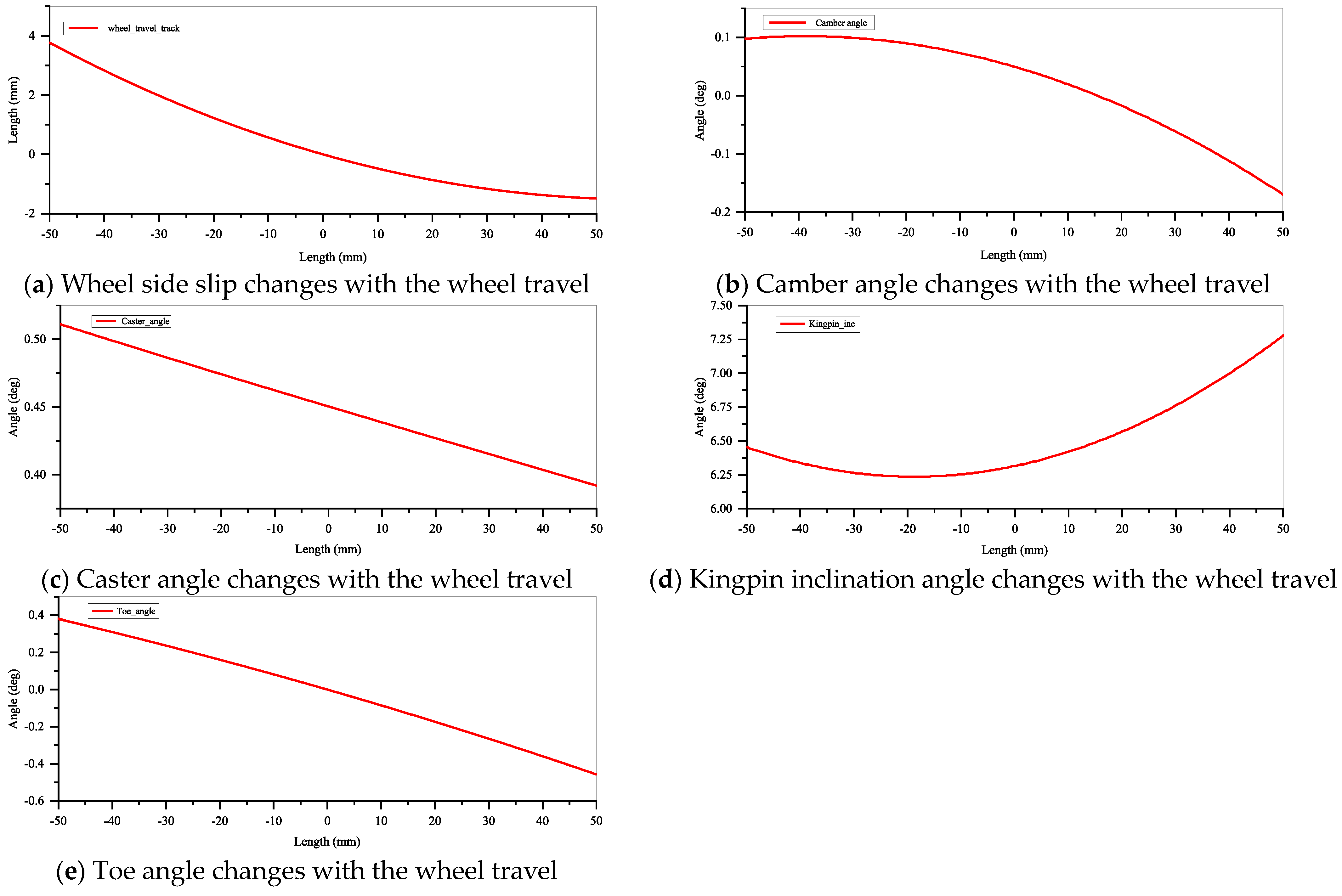
Performing a parallel-wheel travel simulation on the suspension model simulates the actual conditions of suspension motion when the wheel encounters obstacles or other situations that cause the tire to bounce during its operation. Based on the simulation results, a comprehensive analysis of the suspension characteristics under these conditions is conducted. Setting the simulation wheel bounce from −50 mm to 50 mm, the variation in major parameters with wheel travel range is depicted in Figure 3 after the simulation. Utilizing the double-wishbone suspension kinematic model developed in this paper for motion analysis, the comparison in the figure shows a close match between the simulation results and the model’s predictions, thus validating the correctness of the virtual prototype model of the double-wishbone suspension presented in this study.
  • In simulated experiments conducted in ADAMS, the curve of the wheel’s lateral slip with wheel bounce is illustrated in Figure 3a. Based on the analysis of the lateral slip results in the figure, it is observed that the lateral slip of the wheel varies within the range of −1.8 mm–3.8 mm, with a total variation of 5.6 mm. It is generally recommended to control the lateral slip of the wheel within a range of 5 mm for optimal performance during wheel travel. Consequently, optimization measures are required to meet this criterion.
  • The ideal range for camber angle variation is typically 0°–1°. In Figure 3b, the variation range of the camber angle during the wheel bounce travel is −0.17° to 0.1°, and its variation falls within the ideal range, meeting the design requirements.
  • In Figure 3c, within the wheel bounce travel range of −50 mm–50 mm, the caster angle varies within the range of 0.35°–0.52°, which is generally under the design requirements.
  • The reasonable variation range of kingpin inclination angle is typically between 5° and 15°, with 5° being considered optimal for many off-road vehicles. From Figure 3d, it is observed that the caster camber varies within the range of 6.25°–7.3°. Although the variation falls within the requirements, there is still room for optimization.
  • In Figure 3e, it is observed that the variation range of the front toe angle is between 0.38° and −0.42°, indicating a relatively small and acceptable range, and the variation trend aligns with the design requirements.
Through the analysis results, the absolute value of the lateral slip at the wheel contact point reached 5.6 mm. Such a large lateral slip increased tire wear. To control the lateral slip of the double-wishbone front suspension of the mining dump truck, if the slip amount is within a reasonable range, parameterization and optimization analysis of key suspension points are required.
Due to the mutual influence between various suspension performance parameters, to avoid the situation where one performance is improved and other properties have deteriorated, this paper selects the changes in camber angle ψ, toe angle θ, caster angle β , the change in the kingpin inclination angle α and the standard deviation of the change in the side slip amount S lat   of the front suspension tire contact point. These five performance parameters are used as optimization targets, and their respective objective functions are as follows:
  m i n f 1 ( X ) = m i n m a x ψ   m i n f 2 ( X ) = m i n m a x θ   m i n f 3 ( X ) = m i n m a x α   m i n f 4 ( X ) = m i n β ¯   m i n f 5 ( X ) = m i n σ ( S lat )
According to the unified objective method, the above sub-objectives are combined into a unified objective function as shown in Formula (20):
m i n f ( X ) = m i n j = 1 5 w j f j ( X )
According to the characteristics of the suspension and the technical indicators of the car body, the z-coordinates of the front, rear, and outer points of the upper and lower wishbones of the front suspension are parameterized, and design variables are created accordingly.
Due to the technical specifications and structural space of the vehicle itself, this variable of the suspension structure’s hard point parameters cannot be too large. The constraints are in the form of percentage relative values, which are −10.0 and +10.0, respectively.
Considering the numerous hard-point coordinates present in a suspension design, comprehensively addressing all of them will significantly impact optimization speed. Therefore, ADAMS/Insight was used for sensitivity analysis of hard point coordinates, and key influencing factors were selected according to the size of the influence to optimize them. Through DOE (Design of Experiments) screening of linear partial factorial design, 128 iterations were performed to complete the optimization analysis. Evaluation of fit indices, such as R2 = 0.998 and R2adj = 0.998, approaching unity indicates a high reliability of the model.
Ultimately, through optimization analysis, the numerical values of hardpoint coordinates changed. Specific values of the hardpoint coordinates before and after optimization can be found in Table 2.
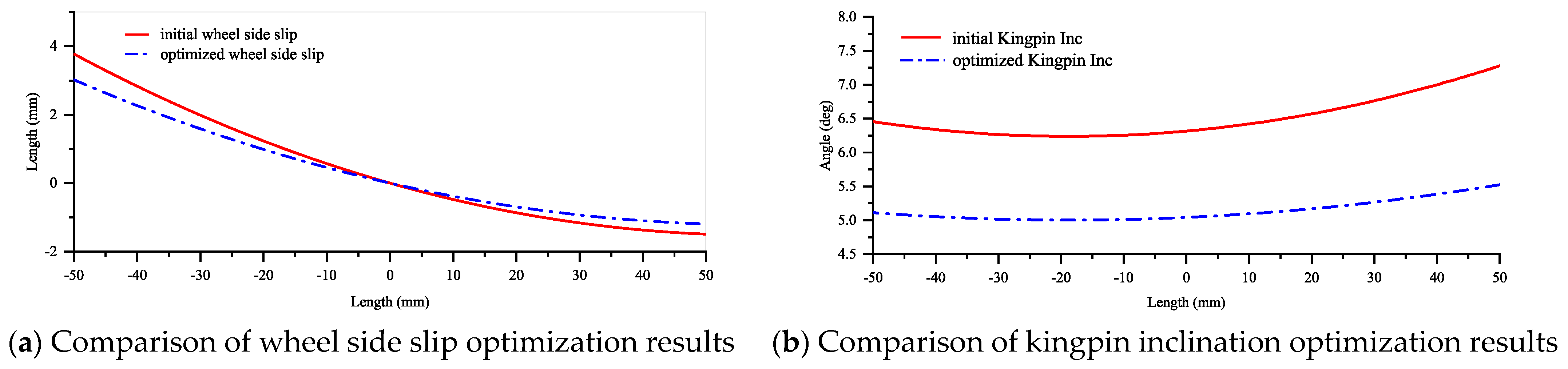
After optimizing the hardpoint coordinates, modifications were made to the original model. Subsequently, a parallel-wheel bounce simulation for the front suspension was conducted again. The results obtained after optimization were then compared and analyzed against the pre-optimized results. The lateral shift variation with wheel travel after optimization is illustrated in Figure 4a, while the caster camber variation with wheel travel after optimization is depicted in Figure 4b.
From the above figures, it can be observed that the lateral slip of the wheel during the optimized wheel travel process is controlled within 3.5 mm (−1~2.5), representing a 37.5% improvement. This meets the design requirements and significantly reduces tire wear. The optimized kingpin inclination angle (5.1–5.6°) not only approximates the optimal angle of 5° more closely, but also exhibits a reduced variation of 0.65° compared to before optimization, achieving a 61% improvement. This meets the design requirements, and the reduction in the kingpin inclination angle contributes to easier steering, achieving the optimization objective.

3. Analysis of Overall Vehicle Handling Stability and Ride Comfort

Establish models for the rear suspension, tires, road surface, powertrain, and vehicle body subsystems. Assemble them using a communication interface and conduct simulation experiments.

3.1. Handling Stability Test

3.1.1. Steady-State Rotation Test

The vehicle handling stability evaluation method used internationally is mainly ISO standard ISO4138-2004 Passenger cars—Steady-state circular driving behavior—Open-loop test methods [21]. This article mainly uses Chinese national standards and related industry standards GB/T 6323-2014, Controllability and stability test procedure for automotive [22]. After consulting the two standards and comparing the test standards of various countries for handling stability, it was found that the main test contents were basically the same, so the Chinese national standards were used for simulation and testing. The steering wheel angle is fixed, and the mining dump truck undergoes smooth acceleration. The forward velocity, lateral acceleration, roll angle, and yaw rate at the center of gravity of the mining dump truck are illustrated in Figure 5.
Following the GB/T6323-2014 standard, three steady-state cornering performance parameters are summarized: a n = 3.73   m / s 2 , U = 0.9183 , K φ = 0.3953 . The evaluation and analysis values for this test are presented in Table 3.
From the above results, it can be concluded that the steady-state cornering performance of this model of mining dump truck, after the front suspension modification with double-wishbone, meets the operational requirements.

3.1.2. Steering Back to the Positive Test

The steering back to the positive simulation test follows the national standard GB/T6323-2014, where the mining dump truck travels on a circular path with a radius of 20 m. The simulation conditions involve driving at a constant initial speed, applying a stepwise angular input to initiate circular motion, releasing the steering wheel when stability is achieved, and resuming straight-line motion after a period. The lateral acceleration, roll angle, and yaw rate of the mining dump truck are illustrated in Figure 6.
From the above figure, it can be observed that:   Δ r = 3.4736 / s , E r = 0.855 s . The evaluation scores are presented in Table 4.
From the above results, it can be concluded that the steering return performance of this model of mining dump truck, after the front suspension modification with double-wishbone, meets the operational requirements.

3.1.3. Snake Test

According to the GB/T6323-2014 standard, the mining dump truck’s speed is set to 40 km/h, and it travels in a serpentine path. During the simulation experiment, the lateral acceleration, roll angle, and yaw rate are illustrated in Figure 7.
The evaluation scores for the snake test, obtained through the analysis of the above figure, are presented in Table 5:
From the above results, it can be concluded that the snake test of this model of mining dump truck, after the front suspension modification with double-wishbone, meets the standard requirements.

3.2. Ride Comfort Test

3.2.1. Random Input Roadway Test

According to the GB/T4970-2009 standard [23], and considering the working environment of mining vehicles, the mining dump truck is operated at a stable speed of 25 km/h on a D-grade road surface. In the test, the lateral acceleration, longitudinal acceleration, vertical acceleration, and power spectra at the center of gravity of the entire vehicle are illustrated in Figure 8.
By analyzing the power spectral density curves of the three-axis accelerations for the vehicle, it is evident that the mining vehicle generates lateral and longitudinal vibrations at peak power spectral density frequencies of 2.26 Hz and 2.37 Hz, respectively, while traveling on a D-grade road surface. These frequencies do not fall within the sensitive range of 0.5–2 Hz. Additionally, the peak power spectral density for vertical acceleration occurs at 2.91 Hz, avoiding the sensitive range of 4 to 12.5 Hz.
The curves obtained from the power spectral density analysis of the three accelerations are processed by generating discrete coordinate values for the curves. The Matlab 2020b software is utilized to solve the frequency functions in each direction, allowing the calculation of the root mean square values for the weighted accelerations along the three axes: a w x = 0.03805 m / s 2 , a w y = 0.04928 m / s 2 , a w z = 0.5132 m / s 2 . Finally, the overall root mean square value of the total weighted acceleration is obtained, a v = 0.517 m / s 2 . Under the requirements of GB/T4970-2009, the root mean square value of weighted acceleration for the vehicle should be within 0.63. Upon comparing the data, it is evident that the mining dump truck with the modified double-wishbone front suspension fully meets the smoothness requirements.

3.2.2. Pulse Input Roadway Test

According to the requirements of the national standard GB/T 4970-2009, square bumps were designed on the road surface for this simulation test. The mining dump truck is made to pass through the road surface at speeds of 15 km/h, 25 km/h, and 45 km/h, respectively. The acceleration in the three directions is shown in Figure 9.
Based on the analysis of the above curves, it can be observed that, when the mining vehicle undergoes the test at 45 km/h, the peak value of vertical acceleration reaches a maximum of 6893.71 mm/s2, indicating good road adaptability and human comfort for this mining dump truck.

4. Comparison with the Integral Front Axle Test Data

In the challenging terrain of mining roads, mining dump trucks often encounter obstacles such as rocks and mounds, leading to significant vibrations. These obstacles not only diminish the comfort of the driver but also have the potential to adversely affect their physical well-being. Therefore, to substantiate the superiority of the modified double-wishbone mining dump truck, this study compares and analyzes the simulation results of the optimized spatial coordinates of hard points with the integral front axle test data. Both the simulation test data and the field test data use the vibration amplitude of a mining dump truck with a full load weight of 572 tons (body weight of 242 tons, load capacity of 330 tons) on a random road surface. The simulation test uses the vehicle equipped with a double-wishbone front suspension with optimized parameters, while the field test data used a mining dump truck equipped with an integral front axle.
Under the specifications outlined in GB5902-86, and considering the actual conditions of mining roads, tests were conducted at speeds of 15 km/h, 25 km/h, and 45 km/h. Figure 10 presents the timedomain graph of the vertical (Z-direction) vibration data at a speed of 25 km/h for a fully loaded mining dump truck. As shown in Figure 10, before the modification of the front suspension to a double-wishbone design, the maximum peak accelerations were 5.12, 4.24, and 3.80, respectively. After incorporating the double-wishbone front suspension, the corresponding peak accelerations decreased to 3.90, 3.36, and 2.75, indicating a reduction of 23.8%, 20.8%, and 27.6%, respectively.

5. Conclusions

The study focused on the modification of the front suspension to a double-wishbone design for a large electric-wheel mining dump truck, and the specific conclusions are as follows:
The dynamic model of the double-wishbone front suspension was established based on the external dimensions and working conditions of a specific model of the mining dump truck. The model was further validated using a kinematic model.
Optimization of the spatial coordinates of the hard points in the double-wishbone front suspension was carried out, resulting in a 37.5% reduction in lateral slip of the wheels and a 61% optimization of the kingpin inclination angle.
The vibration data from simulations of the mining dump truck equipped with the optimized double-wishbone suspension, under pulse conditions at 25 km/h, were compared with the actual vibration data collected from a mining dump truck equipped with an integral front axle at the same speed. The optimization levels were found to be 23.8%, 20.8%, and 27.6% for different parameters.

Author Contributions

J.Z. and X.R. conceived and designed the experiments; J.Z., X.R. and T.L. performed the experiments; J.Z. analyzed the data; Z.D. provided the data; X.R., Z.D. and T.L. provided guidance and recommendations for research; J.Z. contributed to the content and writing of the manuscript. All authors have read and agreed to the published version of the manuscript.

Funding

This research was funded by the Inner Mongolia Autonomous Region Natural Science Foundation (2023QN05031). The funding unit is the Science and Technology Department of Inner Mongolia Autonomous Region, and the funding amount is RMB 100,000.

Institutional Review Board Statement

Not applicable.

Informed Consent Statement

Not applicable.

Data Availability Statement

The data presented in this study are available on request from the corresponding author. The data are not publicly available due to the need for further research.

Acknowledgments

The authors would like to gratefully acknowledge the Inner Mongolia Autonomous Region Natural Science Foundation (2023QN05031), Inner Mongolia Key Laboratory of Intelligent Diagnosis and Control of Mechatronic System, and the School of Mechanical Engineering for their support. Finally, the authors would like to thank the editors and reviewers for their valuable comments and constructive suggestions.

Conflicts of Interest

Author Zhiming Dong was employed by the company Inner Mongolia North Hauler Joint Stock Co., Ltd. Authors Jianqiao Zhao, Xueping Ren and Tongtong Liu declare that the research was conducted in the absence of any commercial or financial relationships that could be construed as a potential conflict of interest.

References

  1. Frimpong, S.; Galecki, G.; Chang, Z. Dump truck operator vibration control in high-impact shovel loading operations. Int. J. Min. Reclam. Environ. 2011, 25, 213–225. [Google Scholar] [CrossRef]
  2. Abdelkareem, M.A.; Makrahy, M.M.; Abd-El-Tawwab, A.M.; El-Razaz, A.; Kamal Ahmed Ali, M.; Moheyeldein, M. An analytical study of the performance indices of articulated truck semi-trailer during three different cases to improve the driver comfort. Proc. Inst. Mech. Eng. Part K J. Multi-Body Dyn. 2018, 232, 84–102. [Google Scholar] [CrossRef]
  3. Gillespie, T. Fundamentals of Vehicle Dynamics; SAE International: Warrendale, PA, USA, 2021. [Google Scholar]
  4. Zhu, H.; Yang, J.; Zhang, Y. Modeling and optimization for pneumatically pitch-interconnected suspensions of a vehicle. J. Sound Vib. 2018, 432, 290–309. [Google Scholar] [CrossRef]
  5. Afkar, A.; Mahmoodi-Kaleibar, M.; Paykani, A. 809. Geometry optimization of double wishbone suspension system via genetic algorithm for handling improvement. J. Vibroeng 2012, 14, 827–837. [Google Scholar]
  6. Kang, Y.; Zhang, W.; Rakheja, S. Relative kinematic and handling performance analyses of independent axle suspensions for a heavy-duty mining truck. Int. J. Heavy Veh. Syst. 2015, 22, 114–136. [Google Scholar] [CrossRef]
  7. Thomson, S.; Hawkes, P. Application of Mining Process Simulation to Reduce Risk, Costs and Improve Operational Performance. In Mining Risk Management; Australasian Institute of Mining and Metallurgy: Carlton, VIC, Australia, 2003; pp. 15–20. [Google Scholar]
  8. Wang, Y.; Li, S.; Cheng, C. Dynamic characteristics of a vehicle-seat-human coupled model with quasi-zero-stiffness isolators. J. Vib. Shock 2016, 35, 190–196. [Google Scholar]
  9. Wang, Y.; Li, S.; Cheng, C.; Su, Y. Adaptive control of a vehicle-seat-human coupled model using quasi-zero-stiffness vibration isolator as seat suspension. J. Mech. Sci. Technol. 2018, 32, 2973–2985. [Google Scholar] [CrossRef]
  10. Sim, K.; Lee, H.; Yoon, J.W.; Choi, C.; Hwang, S.-H. Effectiveness evaluation of hydro-pneumatic and semi-active cab suspension for the improvement of ride comfort of agricultural tractors. J. Terramech. 2017, 69, 23–32. [Google Scholar] [CrossRef]
  11. Xiao, W.; Lu, D.; Song, L.; Guo, H.; Yang, Z. Influence of particle damping on ride comfort of mining dump truck. Mech. Syst. Signal Process. 2020, 136, 106509. [Google Scholar] [CrossRef]
  12. Zou, J.; Guo, X.; Abdelkareem, M.A.; Xu, L.; Zhang, J. Modelling and ride analysis of a hydraulic interconnected suspension based on the hydraulic energy regenerative shock absorbers. Mech. Syst. Signal Process. 2019, 127, 345–369. [Google Scholar] [CrossRef]
  13. Kwon, K.; Seo, M.; Kim, H.; Lee, T.H.; Lee, J.; Min, S. Multi-objective optimisation of hydro-pneumatic suspension with gas–oil emulsion for heavy-duty vehicles. Veh. Syst. Dyn. 2020, 58, 1146–1165. [Google Scholar] [CrossRef]
  14. Cole, D.J. Fundamental issues in suspension design for heavy road vehicles. Veh. Syst. Dyn. 2001, 35, 319–360. [Google Scholar] [CrossRef]
  15. Feng, J.; Matthews, C.; Zheng, S.; Yu, F.; Gao, D. Hierarchical control strategy for active hydropneumatic suspension vehicles based on genetic algorithms. Adv. Mech. Eng. 2015, 7, 951050. [Google Scholar] [CrossRef]
  16. Ataei, M.; Asadi, E.; Goodarzi, A.; Khajepour, A.; Khamesee, M.B. Multi-objective optimization of a hybrid electromagnetic suspension system for ride comfort, road holding and regenerated power. J. Vib. Control 2017, 23, 782–793. [Google Scholar] [CrossRef]
  17. Georgiou, G.; Verros, G.; Natsiavas, S. Multi-objective optimization of quarter-car models with a passive or semi-active suspension system. Veh. Syst. Dyn. 2007, 45, 77–92. [Google Scholar] [CrossRef]
  18. Nagarkar, M.P.; Patil, G.J.V.; Patil, R.N.Z. Optimization of nonlinear quarter car suspension–seat–driver model. J. Adv. Res. 2016, 7, 991–1007. [Google Scholar] [CrossRef] [PubMed]
  19. Wang, J. Multiscale Multibody Dynamics: Motion Formalism Implementation; Springer Nature: Berlin, Germany, 2023. [Google Scholar]
  20. Mo, X.; Zhong, Z.; Han, X.; Yan, X. Kinematics analysis of double-wishbone suspension for diamond-shaped vehicles based on multi-objective optimization. China Mech. Eng. 2009, 20, 374–377. [Google Scholar]
  21. ISO 4138:2004; Passenger Cars-Steady State Circular Driving Behaviour—Open Loop Test Methods. International Standardization Organization: Geneva, Switzerland, 2004.
  22. GB/T 6323-2014; Controllability and Stability Test Procedure for Automotive. General Administration of Quality Supervision. Inspection and Quarantine of the People’s Republic of China, National Standardization Administration of China: Beijing, China, 2014.
  23. GB/T 4970-2009; Method of Running Test—Automotive Ride Comfort. General Administration of Quality Supervision. Inspection and Quarantine of the People’s Republic of China, National Standardization Administration of China: Beijing, China, 2009.
Figure 1. Double-wishbone front suspension.
Applsci 14 01812 g001
Figure 2. Model of the double-wishbone front suspension.
Applsci 14 01812 g002
Figure 3. Changes with the wheel travel.
Applsci 14 01812 g003
Figure 4. Comparison between initial and optimized results.
Applsci 14 01812 g004
Figure 5. Steady-state rotation test. **2 represents the square.
Applsci 14 01812 g005
Figure 6. Steering back to the positive test simulation results.
Applsci 14 01812 g006
Figure 7. Snake test.
Applsci 14 01812 g007aApplsci 14 01812 g007b
Figure 8. Random input roadway test.
Applsci 14 01812 g008aApplsci 14 01812 g008b
Figure 9. Pulse roadway test.
Applsci 14 01812 g009
Figure 10. The response of vertical (Z-direction) vibrations over time.
Applsci 14 01812 g010
Table 1. Initial Hardpoint Coordinate.
Hard PointXYZ
hpl_tierod_inner−1300−18460
hpl_tierod_outer−1236−38000
hpl_uca_outer20−3300347.66
hpl_uca_rear500−1846400
hpl_uca_front−965−1846400
hpl_lca_outer−50−3400−566.99
hpl_lca_rear200−1646.4−500
hpl_lca_front−950−1646.4−500
hpl_wheel_center0−3628.41−77
hpl_top_mount0−2116.942055.09
Table 2. Hardpoint coordinates before and after optimization.
Parameter Before Parameter OptimizationAfter Parameter Optimization
hpl_lca_front.z−500−494.13
hpl_lca_rear.z−500−450.75
hpl_lca_outer.z−566.99−623.18
hpl_uca_front.z400368.63
hpl_uca_rear.z400382.11
hpl_uca_outer.z347.66315.09
Table 3. Steady-state rotation performance evaluation score.
Steady-State Rotation Performance Evaluation ScoreScore
N a n 69.70
N U 94.10
N ϕ 77.43
N W 80.41
Table 4. Steering back to the positive performance evaluation score.
Steering Back to the Positive Performance Evaluation ScoreScore
N Δ r 76.84
N E 64.00
N H 70.42
Table 5. Snake test evaluation score.
Snake Test Evaluation ScoreScore
N γ 93.78
Disclaimer/Publisher’s Note: The statements, opinions and data contained in all publications are solely those of the individual author(s) and contributor(s) and not of MDPI and/or the editor(s). MDPI and/or the editor(s) disclaim responsibility for any injury to people or property resulting from any ideas, methods, instructions or products referred to in the content.

