Article

Research on Kinematics and Efficiency Calculation of Binary Logic Planetary Gearbox Based on Graph Theory

1
Key Laboratory of Vehicle Transmission, China North Vehicle Research Institute, Beijing 100072, China
2
School of Mechanical Engineering, Hebei University of Science and Technology, Shijiazhuang 050018, China
*
Author to whom correspondence should be addressed.
Appl. Sci. 2024, 14(5), 1773; https://doi.org/10.3390/app14051773
Submission received: 29 November 2023 / Revised: 7 January 2024 / Accepted: 12 January 2024 / Published: 22 February 2024
(This article belongs to the Section Mechanical Engineering)

Abstract

:
In this paper, the graph theory model of the kinematics of the double internal meshing planetary gear is established by splitting the k value of the planetary gear, the system matrix of the dual-state logic planetary gear transmission is assembled, the logic characteristics of the dual-state logic planetary gear transmission control are analyzed, the logic characteristic table of the 32-gear control is established, and the system model of the kinematics analysis and calculation of the entire planetary gear transmission is established. The expressions of rotational speed and transmission ratio of each component (including planetary gear) of the planetary gear in 32 gears are solved and obtained. The efficiency expression of each gear is derived through the Kleinas method, the calculation of the transmission ratio and efficiency of the 32 gears is completed, and the system efficiency diagram is drawn, which provides a reliable basis for the structural design, shift dynamic simulation analysis, and test verification of the dual-state logic planetary transmission.

1. Introduction

Due to the demand for technical indicators of high speed and heavy load equipment, the performance requirements of planetary gear transmission are becoming higher and higher. At the same time, it must meet the requirements of compact structure, high power density, and high reliability. Therefore, the planetary transmission technology with compact structure and high power density also needs to be further improved. In view of the shortcomings of planetary transmission technology, such as the uneven load between multiple planetary gears caused by the deformation of manufacturing and installation load, and the low efficiency of the external meshing gear pair in the ordinary planetary gear train, some scholars have adopted the double internal meshing coplanar planetary gear transmission, which has made major improvements in three aspects: First, the positive planetary gear train is adopted, and the sun gear, planetary gear and gear ring all adopt the internal meshing form. Compared with the external meshing gear in the negative sign row, the coincidence degree is higher and the efficiency is higher. Second, improvements result from changing the tooth profile of planetary gears, replacing the traditional involute tooth profile with the tooth profile with a long tooth mesh line, and replacing the conventional involute tooth profile with the addendum tooth profile and its conjugate meshing tooth profile. In the direction of the meshing line (straight line) of the traditional involute gear, the tooth top and tooth root of the driving gear and the tooth root and tooth top of the passive gear, respectively, realize the meshing transmission mainly in the form of rolling friction. The tooth profile of the double internal meshing coplanar gear is replaced by the conjugate tooth profile of the tooth top profile on the tooth root profile. The meshing of the driving gear and the passive gear is realized by a sliding contact on a segment of arc meshing line. For a single pair of gears, the number of teeth engaged by the new tooth profile gear is much more than that of the traditional involute tooth profile gear, with increased coincidence and high efficiency, as shown in Figure 1a. The third aspect is the use of coplanar planetary array structure. In the positive planetary array, two pairs of internal meshing gear pairs that are usually not in a plane are designed to work in a plane, reducing the axial size. One internal meshing gear pair is embedded in the ring gear planetary gear, and another internal meshing gear pair is embedded in the ring gear planetary gear (ring gear and planetary gear, see Figure 1b). Because the embedded ring gear becomes the internal gear in the planetary gear, the embedded planetary gear also becomes the sun gear. In order to make the structure clear, the frame model is not built. The brake frame or any two components in the planetary array form two transmission ratios (including 1:1). This coplanar structure design meets the requirements of a small size, fewer parts, and a compact structure while ensuring the transmission ratio.
As a common mechanical transmission device, planetary gear transmission is widely used in machinery, engineering and automotive fields. In the tank transmission system, planetary gear has a very important role, including driving tank track system, speed control, steering system, etc. The purpose of the application of planetary gear transmission in tanks is to provide efficient, flexible and reliable power transmission to meet the diverse needs of tanks in different battlefield environments. The planetary gear is mainly composed of several key components, including a sun wheel, planet wheel, ring wheel, double row roller bearing and load distribution mechanism. Due to prolonged heavy loading and harsh working conditions, planetary gears may inevitably experience failure forms such as gear tooth surface wear. Z Shen et al. [1] proposed a pure torsional dynamic model of planetary gear wear based on Archard’s equation to evaluate gear wear and analyzed the influence of gear wear on planetary gear dynamic parameters and vibration response. C Yuksel et al. [2] established a computational model of planetary gear transmission and studied the influence of surface wear on the dynamic characteristics of a typical planetary gear transmission. Many scholars have conducted further research on issues such as tooth surface wear. A Kahraman et al. [3] combined the torsional dynamics model with the surface wear model to study the interaction between surface wear and dynamic response of planetary gear sets. M Gao et al. [4] proposed a stiffness model based on the three-segment tooth profile equation to calculate the meshing stiffness under healthy wear conditions and established the meshing relative displacement function considering the influence of back backlash and wear thickness. J Wang et al. [5] coupled the Archard wear model with a nonlinear dynamics model and proposed a new solar wheel RUL dynamic evaluation method to accurately evaluate the remaining service life of gears with worn surfaces. Planetary gear transmission is widely used in various fields due to its advantages of compact structure, light weight, large carrying capacity, large transmission ratio and high transmission efficiency [6]. The strong impact inside the gearbox will cause vibration damage, and the dynamics and vibration characteristics of planetary gears have been paid more and more attention [7,8,9]. Kahraman et al. [10] studied the influence of dynamics on the gear stress, that is, the change in the wheel rim thickness and the number of planets. Ambarisha et al. [11] used the lumped parameter model and finite element model to study the complex nonlinear dynamic behavior of a positive planetary gear. In order to obtain an accurate vibration response prediction and understand the coupled vibration mechanism in planetary gear systems, J Wei et al. [12] proposed a comprehensive, fully coupled, dynamic modeling method using virtual equivalent shaft elements to improve the reliability of planetary gear systems. The structure of planetary gears determines their functional strength. In order to optimize the superiority of the structure, many scholars have conducted a lot of research on this. DP Karaivanov et al. [13] proposed a multi-objective selection of the structural scheme and parameters of a dual carrier planetary gear system, considering the use of a dual carrier planetary gear system with three and four outer shafts. The torque method was used to select among all possible structural schemes of the discussed planetary gear system. W Qiu et al. [14] studied the kinematic principles and structural symmetry of coaxial and noncoaxial transmission of linked planetary gear trains, extended the composite structure based on linked planetary gear trains, and conducted a calculation method for the reduction ratio of the extended structure. A Shahabi et al. [15] studied the influence of the pressure angle on the meshing stiffness of the meshing gear and the dynamic model of the planetary gear group in view of the planetary gear structure. Y Fan et al. [16] designed an automatic transmission with improved planetary gear using the lever method and carried out kinematics and dynamics analysis. With the development of optimization methods for planetary gear structure, an optimization method based on graph theory has been proposed. Many scholars began to study this. H Xue et al. [17] used graph theory to analyze the kinematics, static force and power flow of planetary gear systems. EL Esmail et al. [18] used graph theory to represent planetary gear trains (PGT), developed a procedure to identify fundamental leverage entities (FGE) and developed an algorithm to detect the degenerate structure of PGTs using the concept of FGEs and the notation of related adjacency matrices. VR Shanmukhasundaram et al. [19] proposed a graph theory-based method for detecting degenerate planetary gear train diagrams in enumeration sets. Y Fan et al. [20] proposed a transmission performance analysis method based on graph theory and matrix equations to improve the transmission performance of planetary gear automatic transmission. S Fu et al. [21] proposed a design method of a fixed shaft gearbox transmission scheme based on graph theory and realized the type of synthesis and number synthesis of gearbox transmission scheme. J Mustafa et al. [22] proposed an innovative Wiener number-based method to detect isomerism through graph theory for all different outer ring gear mechanisms with multiple degrees of freedom and different numbers of links. According to the above research, this paper will carry out research on the kinematics and efficiency calculation of two-state logic planetary transmission based on graph theory.
Based on the above research, it is known that the double inner meshing planetary rows have the advantages of high torque transmission, smooth output, compact design, etc. In this paper, the kinematic graph theory model of the double inner meshing planetary rows is established, the system matrix of the two-state logical planetary transmission gearbox is assembled, each gear of the gearbox is calculated and analyzed, and the system efficiency diagram is drawn. It provides a reliable basis for subsequent simulation analysis and test verification.

2. Dual-State Logic Drive

The core technology of the dual-state logic transmission is the planetary transmission technology of the double internal meshing coplanar gear with a large coincidence tooth profile. Dual-state logic transmission technology is the unique transmission technology first developed by Ker-Train Company in Canada. It can give full play to the characteristics of engine power and has the advantages similar to CVT technology of stepless transmission; high transmission efficiency of variable speed gear and good fuel economy; fast acceleration performance; no need to reduce the vehicle speed during the steering process; high mobility; the step ratio between gears is small; the range of the transmission ratio is large; automatic gear shifting can be realized; the handling performance is good; the reliability is high. Without a hydraulic torque converter, it adopts coplanar meshing technology with large coincidence and a long contact line, an efficient conical friction disc clutch and a steering differential system with full gears, compact structure and high power density.
On the basis of dual-state logic transmission technology, a prototype SG-850 has been developed abroad, with a maximum power of 850 hp, a maximum torque of 2700 Nm, a maximum input speed of 2300 rpm, a vehicle weight of 35 tons and a transmission weight of 1750 kg. It has completed 18,000 km of real vehicle tests on the Pizarro model. KTR has adopted the above patented tooth shape technology to meet the market demand for the automatic driving function of vehicles. The new transmission system Gemini III developed by the company is a dual-state logic transmission device with 900 horsepower and 32 gears, which is a better platform to replace the current 40–50-ton tracked vehicle transmission system. Both the Gemini III and the fan transmission system adopt wire control technology, achieving integration with the automatic driving vehicle. Due to the transmission efficiency of more than 90%, the Gemini III can provide more cruise power to the vehicle, save fuel, improve the range and enhance the tactical and logistical support capabilities. KTR also developed the first generation of the “Alpha” unit for the US Tank Vehicle Research and Development Project (TARDEC). KTR is also actively developing the second generation “Beta” unit, with the goal of improving reliability, optimizing the efficiency of the unit subsystem, reducing weight, reducing design and manufacturing costs, developing the software and hardware of vehicle control and realizing the fully controlled transmission system by wire.
The dual-state logic transmission is composed of a series of coplanar gear planetary array modules in series. Each module achieves its two transmission ratio output modes by the control unit that controls the conical friction plate. The output transmission ratio of the two components of the planetary array is 1:1, and the other transmission ratio is achieved by formulating one component of the planetary array. A single row can form two transmission ratios, and n rows can form 2n gear transmission ratio in series. If the maximum transmission ratio of the gearbox is R and the gear ratio is X, then X = R 1 2 n 1 .

3. Double-State Logic Drive–Double Internal Meshing Coplanar Gear Planetary Array Characteristic Analysis

Planetary row can be divided into a positive and negative row. The negative row is shown in Figure 2a, and the positive row is shown in Figure 2b. The negative row is a planetary row with an external meshing transmission, and the positive row is a planetary row with two planetary gears to achieve two external meshing transmissions. The characteristic equation of negative sign row is ns + knr (1 + k)nc = 0; the characteristic equation of the positive row is nsknr − (1 − k)nc = 0. Here, k = z r z s , and k is the ratio of the number of teeth between the planetary gear ring and the sun gear. We used graph theory to express the topological structure of the planetary array and form a graph theory model, which is convenient for the calculation and analysis of the kinematics and dynamics of the planetary array. In the graph theory model of the transmission system, points are used to represent the rotating components, and edges (the connecting line between two points) are used to represent the relative motion relationship (kinematic pair) between points (components). The rotating pairs with coaxial axes in the gear train are represented by solid line edges, and the gear pairs in the gear train are represented by dotted line edges. The graph theory representation model of an ordinary planetary array is shown in Figure 2a, and the points s, p, c and r represent the components of the sun gear, the planet gear, the frame and the gear ring, respectively. Here, the planet gear also becomes a separate component.

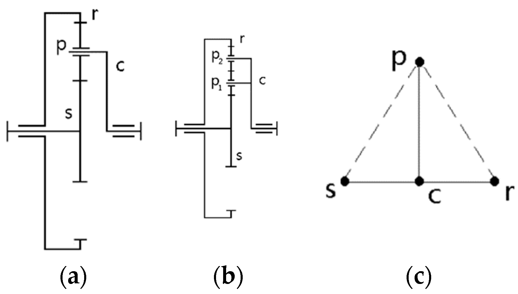
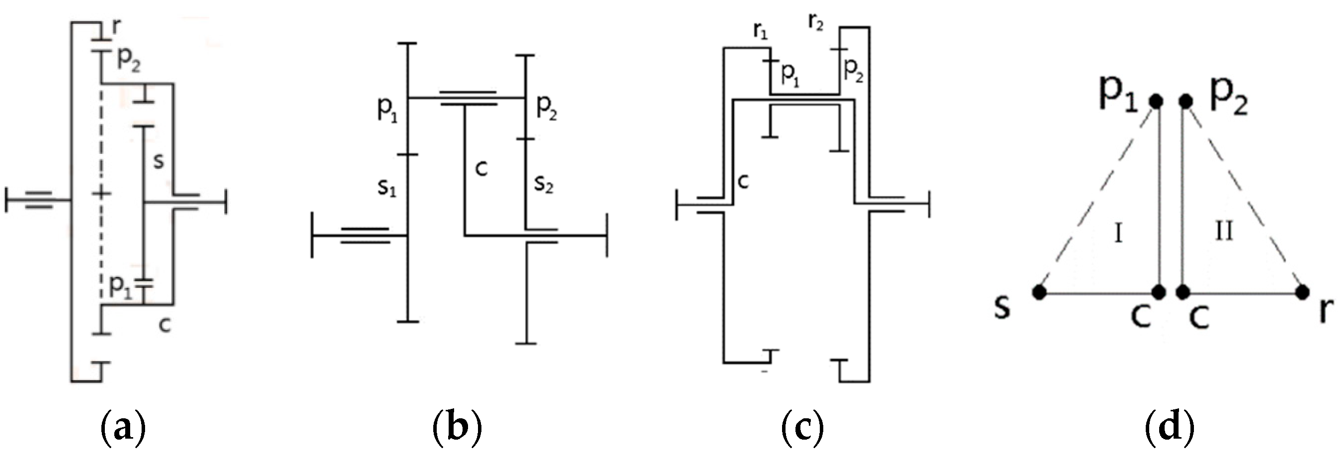
3.1. Graph Theory Model of Coplanar Gear Planetary Array

The coplanar gear is a positive planet row. The positive planet excludes the three types shown in Figure 2b above. Figure 3a is the coplanar gear planetary array. In the gearbox studied in this paper, the planetary gear p1 and the sun gear s (internal meshing) and the gear ring r and the planetary gear p2 are basically designed in the same plane. The graph theory expression of the positive planetary array in Figure 3 is shown in Figure 3d. In the ordinary negative planetary array (including a planetary gear), it is usually coincident p1 with p2; that is, the cp1 edge is coincident with the cp2 edge, which is an edge cp.

3.2. Analysis of Rotational Speed and Speed Ratio of Single-Row Coplanar Gear Planetary Array

In the study of the graph theory model of the transmission system, the basic circuit is usually used to calculate and analyze the speed, torque or power flow of the planetary gear. The basic circuit is a closed circuit composed of three components, which is composed of two meshing gears and the planet carrier between its rotating shaft. From this, we can see the characteristics of the basic circuit: a closed circuit composed of three points (components), one gear pair edge (dotted line) and two rotary pair edges (solid line). The number of basic circuits are equal to the number of gear pairs. In a planetary basic gear train, there are two basic circuits which can form two basic circuit equations. In Figure 3d, the coplanar gear planetary array contains (p1, s) c and (p2, r) c, two basic circuits, and the basic circuit equation is as follows [23]:
ω s I ω c I = i s p 1 ( ω p 1 I ω c I )
ω p 2 I I ω c I I = i p 2 r ( ω r I I ω c I I )
ω p 1 I = ω p 2 I I
ωs, ωp1, ωp2, ωc and ωr, respectively, represent the rotational speed of the corresponding components in the basic circuit, namely, the sun gear, the planet gear 1, the planet gear 2, the planet carrier and the gear ring, where ωp1 = ωp2, isp1 = zp1/zs = k1 and ip21 = zr/zp2 = k2, respectively, represent the tooth number ratio of the two internal meshing gears of the planet gear 1 and the sun gear, and the planet gear 2 and the gear ring. Then, the whole coplanar gear characteristic parameter k = k1 × k2 is rewritten with k1 and k2 for the above basic loop equation, the circuit mark is removed, ωp1 and ωp1 are replaced with ωp to obtain the following equation:
ω s k 1 ω p ( 1 k 1 ) ω c = 0
ω p k 2 ω r ( 1 k 2 ) ω c = 0
Written in the form of a transmission ratio matrix, the following equation is obtained:
A ω = | 1 k 1 0 ( 1 k 1 ) 0 1 k 2 ( 1 k 2 ) | [ ω s ω p ω r ω c ] = 0
That is, A × ω = 0, where A is the transmission ratio matrix, ω is the coefficient of the angular velocity of Equations (4) and (5), and Equation (6) represents the case of a single planet of a coplanar gear lining up two loops, which is the rotational speed characteristic matrix of a single planetary row of a coplanar gear. The following establishes the corresponding speed characteristic equation (matrix) for a gearbox composed of five coplanar gear planetary rows and one ordinary planetary row connected in series.

3.3. Speed Matrix Analysis of a Coplanar Gear Planetary Gearbox

A planetary gearbox has a total of six planetary rows which are arranged in order of 1, r, 2, 3, 4 and 5. The first five rows are coplanar gear planetary rows, and the last row is a cylindrical spur gear ordinary planetary row. The r row is used to achieve reverse gear. There are 32 gears in the forward gear and 32 gears in the reverse gear. See Figure 4 for the schematic diagram. The numbers 1–13 represent the number of planetary gear sets, C1–C5 represents the clutch, a total of five, and B1–B5 represents the brake, a total of five.
In this paper, planetary rows 1, r, 2, 3, 4 and 5 are named successively according to the arrangement order of each row in the transmission structure, and the speed characteristic matrix of the transmission is obtained by deducing the speed matrix of each single row and assembling it into the system speed characteristic matrix.
Since there are connectors between the transmission rows, power transmission between the rows is formed. The connecting parts between the transmission rows are composed of the following: the sun gear in row 1 and the frame in row r, the sun gear in row r and the sun gear in row 2, the gear ring in row 2 and the gear ring in row 3, the sun gear in row 3 and the sun gear in row 4, and the gear ring in row 4 and the sun gear in row 5, which are connected, respectively, forming the following connecting parts matrix (7).
1   0   0   0   0   0   0 1   0   0   0   0   0   0   0   0   0   0   0   0   0   0   0   0 0   0   0   0   1   0   0   0   0 1   0   0   0   0   0   0   0   0   0   0   0   0   0   0 0   0   0   0   0   0   0   0   0   0   1   0   0   0 1   0   0   0   0   0   0   0   0   0 0   0   0   0   0   0   0   0   0   0   0   0   1   0   0   0 1   0   0   0   0   0   0   0 0   0   0   0   0   0   0   0   0   0   0   0   0   0   0   0   0   0   1   0 1   0   0   0 ω s 1 ω p 1 ω r 1 ω c 1 · ω r 5 ω c 5 = 0
In practice, the combination or separation of the brake or clutch can establish the gear to make the vehicle run normally. For the above gearbox, according to the corresponding components of braking, the speed characteristic matrix of brake parts is established below; see matrix expression (8). Similarly, according to the components combined by the clutch, the speed of the two components can be equal to form the corresponding clutch speed characteristic matrix below; see matrix expression (9).
0   0   1   0   0   0   0   0   0   0   0   0   0   0   0   0   0   0   0   0   0   0   0   0 0   0   0   0   0   0   1   0   0   0   0   0   0   0   0   0   0   0   0   0   0   0   0   0 0   0   0   0   0   0   0   0   0   0   0   1   0   0   0   0   0   0   0   0   0   0   0   0 0   0   0   0   0   0   0   0   0   0   0   0   0   0   0   1   0   0   0   0   0   0   0   0 0   0   0   0   0   0   0   0   0   0   0   0   0   0   0   0   0   0   0   1   0   0   0   0 0   0   0   0   0   0   0   0   0   0   0   0   0   0   0   0   0   0   0   0   0   0   1   0 ω s 1 ω p 1 ω r 1 ω c 1 · ω r 5 ω c 5 = 0
0   0   1 1   0   0   0   0   0   0   0   0   0   0   0   0   0   0   0   0   0   0   0   0 0   0   0   0   0   0   1 1   0   0   0   0   0   0   0   0   0   0   0   0   0   0   0   0 0   0   0   0   0   0   0   0   0   0   1 1   0   0   0   0   0   0   0   0   0   0   0   0 0   0   0   0   0   0   0   0   0   0   0   0   1   0   0 1   0   0   0   0   0   0   0   0 0   0   0   0   0   0   0   0   0   0   0   0   0   0   0   0   1   0   0 1   0   0   0   0 0   0   0   0   0   0   0   0   0   0   0   0   0   0   0   0   0   0   0   0   1   0 1   0 ω s 1 ω p 1 ω r 1 ω c 1 · ω r 5 ω c 5 = 0

3.4. Analysis of Gear and Dual-State Logic Characteristics of Coplanar Gear Planetary Transmission

There are two controls (brake B and clutch C) in a single coplanar gear planetary row. It is a planetary row with three degrees of freedom. It needs to execute one control to input the power source before it can output. Here, 1 represents combination and 0 represents separation, State indicates the non-working condition, and √ state indicates the working condition. Because there is a logical relationship between brake B and clutch C in the same planetary row of the gearbox, B C = 0 and B C = 1. It indicates that B and C cannot execute simultaneously and B and C must execute at least one piece. Therefore, in the actual working state, there are only two states BC = 01 and BC = 10, of which there must be B ¯ = C or C ¯ = B . It can be seen that the actuating characteristics of the single coplanar gear planetary brake and clutch are the same as the XOR logic characteristics of the binary in the digital circuit, and the truth value of the XOR expression are shown in Table 1.
Due to the fact that an n coplanar planetary transmission can achieve 2 nth power gears, according to the exclusive characteristics of the control brake and clutch of the single coplanar gear planetary bank, the logical relation between the gear shift and the control is derived.
Due to the maximum transmission ratio in the first gear of the gearbox, the principle is to use the maximum (and greater than 1) transmission ratio of each row at work, due to the assumption of the corresponding logical state of the transmission gear and control components mentioned above that the input of each row is a sun gear which is connected to the next planetary row in a deceleration state. But it can be seen from the schematic diagram of the bimodal logic mentioned above that the X1 and X3 rows use ring gear input. If the corresponding brake is brake, its single-row transmission ratio is less than 1, which belongs to the growth state. Therefore, in order to achieve the maximum transmission ratio of 1, the X1 and X3 planetary row controls should work with C1 and C3 (transmission ratio greater than 1). So, the positions of B1, B3, C1 and C3 in the logical relationship table corresponding to the transmission gears and control components mentioned above should be interchanged; at the same time, because the r row is a reverse gear row, this paper only studies its forward 32 gears, so Cr replaces Br (Br is braking in reverse gear).

3.5. Transmission Control Logic Characteristic Matrix

Due to the implementation of various gears in the planetary gearbox, the joint participation of various planetary gears and their control components is required. Because each row of elements in the control matrix corresponds to the speed vector of each row of sun wheels, planet wheels, gear rings and frames in accordance with the order of 1, r, 2, 3, 4 amd 5 planet rows, when forming each gear, the transmission control speed characteristic matrix needs to be selected. If the corresponding row vector of the non-braking brake is eliminated, the clutch in the same planetary platoon must be combined when achieving gear, and its corresponding row vector in the transmission control speed characteristic matrix must be preserved. Assuming its retention state is set to 1 and its truncation state is set to 0, this is consistent with the logical characteristics of the control element. Therefore, each gear vector in the transmission control logic characteristic matrix is used to form a diagonal matrix and the transmission control speed characteristic matrix is multiplied to obtain the transmission control speed characteristic matrix for each gear.

3.6. The Velocity Characteristic Matrix of Each Gear of a Coplanar Gear Planetary Transmission

The planetary transmission speed matrix of each gear is composed of the planetary transmission speed matrix, the coupling speed matrix and the corresponding control speed matrix of each gear. The control matrix of each gear is obtained by converting the row vector (12 × 1) of each gear in the control logic characteristic matrix and the control speed characteristic (12 × 24) matrix. Because there are only six ones in the row vectors of each gear (with the remaining six being 0), a 6 × 24 execution matrix for each gear control is formed. Together with the coupling of the speed characteristic (5 × 24) matrix, the planetary transmission speed matrix (12 × 24) and an input (with a speed of 1), a 24 × 24 planetary transmission speed matrix is formed, so as to achieve the calculation of the speed of each component of the planetary transmission sun wheel, planetary wheel, gear ring and planetary frame.

4. Analysis and Calculation of Speed and Speed Ratio of Two-State Logic Transmission Gearbox

For the characteristic of 64 gears, the velocity characteristic matrix equation can be used to analyze and calculate the speed and the corresponding transmission ratio of each gear. The following is limited by space, taking the first five gears of the gearbox and the first three rows of the planetary platoon studied in this paper as examples. The speed characteristics of each component in the planetary platoon at each gear are calculated, and the corresponding expressions are obtained. The details are shown in Table 2 below. The k values used in the calculation of the surface transmission ratio are as follows: k11 = 1.0606, k12 = 1.0404, k21 = 1.13636, k22 = 1.07317, k31 = 1.27027 and k32 = 1.16949.

5. Analysis and Calculation of Power Loss and Efficiency of a Two-State Logic Transmission

The power loss of planetary transmission is currently mainly analyzed and calculated using the meshing power method, mainly calculating the meshing power during the planetary gear transmission process. This is because the planetary transmission mechanism usually adopts the method of conversion mechanism when calculating its speed or transmission ratio. By attaching a virtual rotation speed opposite to the rotation speed of the planetary array system, the planetary array system can be viewed as a “fixed axis gear” system with zero rotation speed of the planetary array. However, the relative speed and friction condition of the planetary carrier between the gears in the original planetary gear system have not changed, and the meshing power between the converted “fixed shaft gear” and the gears in the original planetary gear train remains unchanged.
Since the input power pi is equal to the sum of the output power po and the loss power pl, the efficiency of the gear transmission is the ratio of the output power po to the input power pi:
η = P o P i = P i P l P i
It is assumed that the tooth ring in the planetary row or the sun wheel has a fixed value, there is no fixed component j, the speed is ωj, the torque acting on the above is Mj and the rotational torque of the frame is ωh and Mh, respectively. So, the meshing power of component j is P m e s h = M j ω j ω h = M j ω j ( 1 ω h ω j ) . The speed ratio ω h ω j between frame h and component j is sometimes greater than 1 and sometimes less than 1 in different types of planetary arrays. There are two situations where the converted meshing power P m e s h and the transmitted power P j = M j ω j of the original gear train have the same or different directions, which brings complex direction judgments to power flow calculations. The Kleinas efficiency calculation formula effectively solves this complex situation and provides a shortcut for calculating power loss and efficiency. The following uses the Cleinas efficiency calculation formula to calculate the efficiency of the above gear (limited to space), respectively, through the kinematic transmission ratio and the dynamic transmission ratio. For the first gear, the formula is as follows:
i = k 21 k 22 k 41 k 42 ( 1 + k 51 k 52 ) = k 2 k 4 ( 1 + k 5 )
Among k 2 = k 21 k 22 , k 4 = k 41 k 42 and k 5 = k 51 k 52 , it is also the characteristic parameter value of each single planet row. So, the dynamic transmission ratio is calculated by i ˜ = k 2 ¯ k 4 ¯ ( 1 + k 5 ¯ ) .
ln i k 2 = k 2 ln k 2 ¯   k 4 ¯ ( 1 + k 5 ¯ ) = k 2 ln k 2 + ln k 4 + ln 1 + k 5 = 1 k 2
ln i k 4 = k 4 ln k 2 ¯   k 4 ¯ ( 1 + k 5 ¯ ) = k 4 ln k 2 + ln k 4 + ln 1 + k 5 = 1 k 4
ln i k 5 = k 5 ln k 2 ¯   k 4 ¯ ( 1 + k 5 ¯ ) = k 5 ln k 2 + ln k 4 + ln 1 + k 5 = 1 1 + k 5
i ~ = k 2 η 2 x 2 k 4 η 2 x 4 1 + k 5 η i n η o u t x 5 = k 2 η 2 k 4 η 2 ( 1 + k 5 η i n η o u t )
η 1 = i ~ i = k 2 η 4 k 4 ( 1 + k 5 η i n η o u t ) k 2 k 4 ( 1 + k 5 ) = η 4 ( 1 + k 5 η i n η o u t ) ( 1 + k 5 )
According to Equations (12)–(15), the partial derivative of k is greater than 0, and x 2 , x 4 and x 5 are equal to 1, and then, i ~ is obtained. Finally, the final expression is obtained according to the Cleinus efficiency formula.
When the gear meshing efficiency is calculated using high coincidence double internal meshing gears, η = 0.985 (0.99), ηin = 0.98 (ordinary internal meshing) and ηout = 0.97 (ordinary external meshing). The efficiency of the calculated gears (the first five as an example) is shown in the Table 3 below.
The efficiency of each gear of the aforementioned dual-state logic planetary gearbox is plotted as a general efficiency diagram as follows. In the Figure 5, the red curve is the gear efficiency of the ordinary planetary gear and the blue curve is the gear efficiency of the two-state logical planetary transmission, which improves the gear efficiency of the ordinary planetary gear transmission by an average of 2.6%.
Compared with other studies, the efficiency loss of gear six in this paper is the largest, which is due to the large number of planetary rows involved in the working condition. Specific solutions include optimizing design parameters and changing the number of planetary rows.

6. Conclusions

  • Due to the particularity of the double internal meshing planetary row, this paper splits the k value of the planetary row, establishes its graph theory model and its corresponding speed equation, and uses the standard form of the equations to assemble the kinematics equation of the whole two-state logical planetary transmission to realize the calculation and analysis of the speed (speed ratio) expression of each gear. This provides strong support for further optimization and design of the transmission. Through in-depth understanding of the kinematic characteristics of the double inner meshing planetary rows, the corresponding transmission system can be better designed and improved, and its performance and efficiency can be improved.
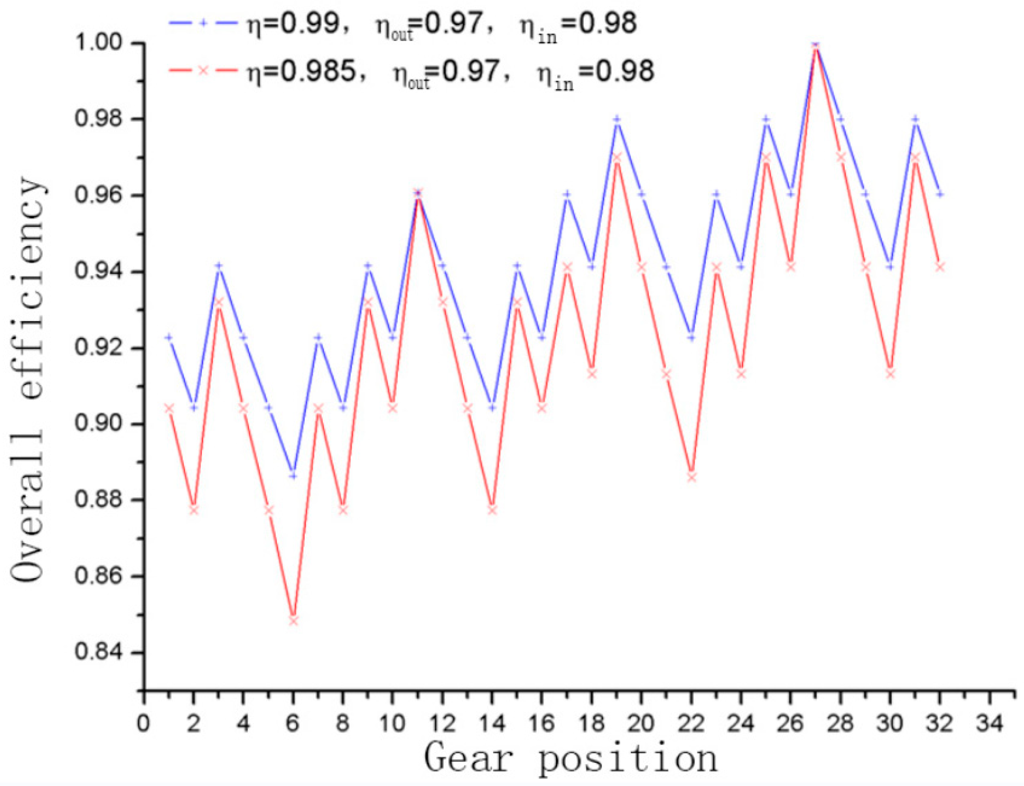
  • The efficiency improvement in a planetary gearbox with dual internal meshing gears is evident compared to traditional conventional planetary gearboxes. As can be seen from the figure above, when the efficiency of the double inner meshing gear with a large contact degree changes from 0.985 to 0.99, the efficiency of the entire two-state logic double inner meshing planetary transmission is significantly improved. In the two-state logic planetary transmission, the efficiency gradually increases with the rise in gear, especially when the speed is close to the maximum, giving an efficiency roughly above 95%. The low efficiency of individual gears, such as sixth gear, is due to the large number of planetary rows involved in the working condition (four rows), so the meshing power loss is large. In the follow-up study, parameters such as module and meshing angle of the gear can be optimized, and the number of planetary rows can be adjusted in the design to reduce the meshing power loss.
  • Based on the graph theory method, this paper establishes the speed and efficiency analysis and calculation model of 32 gears (this paper only studies the 32 gears in the forward gear) in full gear working conditions and establishes the corresponding program model to determine the efficiency calculation and power loss analysis of the whole planetary gearbox in all working conditions, laying a foundation for further research.
  • In this paper, from the perspective of digital circuits, the corresponding logical relationship table is established between each gear control and each gear of two-state logic transmission, which provides a clear and feasible basis for the analysis and simulation of speed, torque, efficiency and automatic shift.

Author Contributions

Conceptualization, S.C.; Methodology, S.C. and Y.C.; Validation, Q.Z. and J.S.; Formal analysis, Q.Z. and Z.W.; Resources, S.C.; Data curation, J.S. and Y.C.; Writing—original draft, Q.Z.; Writing—review & editing, Z.W. and J.S.; Supervision, Q.Z. and Z.W.; Project administration, Y.C.; Funding acquisition, Y.C. All authors have read and agreed to the published version of the manuscript.

Funding

This work is partially supported by the National Natural Science Foundation of China: 51904088; the S&T Program of Hebei (20310803D); the Central Guidance on Local Science and Technology Development Fund of Hebei Province (226Z1906G); the Natural Science Foundation of Hebei Province (E2020208052; E2019208144; E2021208004); the Hebei University Science and Technology Research Youth Fund Project (QN2021061). Natural Science Research Projects in Higher Education Institutions of Hebei Province (CXY2024038).

Institutional Review Board Statement

Not applicable.

Informed Consent Statement

Not applicable.

Data Availability Statement

Data are contained within the article.

Conflicts of Interest

The authors declare no conflict of interest.

References

  1. Shen, Z.; Qiao, B.; Yang, L.; Luo, W.; Yang, Z.; Chen, X. Fault mechanism and dynamic modeling of planetary gear with gear wear. Mech. Mach. Theory 2021, 155, 104098. [Google Scholar] [CrossRef]
  2. Yuksel, C.; Kahraman, A. Dynamic tooth loads of planetary gear sets having tooth profile wear. Mech. Mach. Theory 2004, 39, 695–715. [Google Scholar] [CrossRef]
  3. Kahraman, A.; Ding, H. A methodology to predict surface wear of planetary gears under dynamic conditions. Mech. Based Des. Struct. Mach. 2010, 38, 493–515. [Google Scholar] [CrossRef]
  4. Gao, M.; Shang, Z.; Li, W.; Liu, F.; Pang, H.; Liu, J. Analysis of Wear Mechanism and Fault Characteristics of Planet Gears with Multiple Wear Types in Planetary Gearbox. J. Vib. Eng. Technol. 2023, 11, 945–975. [Google Scholar] [CrossRef]
  5. Wang, J.; Zhang, J. Assessment of Residual Useful Life of Sun Gear in a Planetary Gearbox Based on Dynamic Wear Behaviors Analyses. Machines 2023, 11, 149. [Google Scholar] [CrossRef]
  6. Bodas, A.; Kahraman, A. Influence of carrier and gear manufacturing errors on the static load sharing behavior of planetary gear sets. JSME Int. J. Ser. C Mech. Syst. Mach. Elem. Manuf. 2004, 47, 908–915. [Google Scholar] [CrossRef]
  7. Lei, Y.; Liu, Z.; Wu, X.; Li, N.; Chen, W.; Lin, J. Health condition identification of multi-stage planetary gearboxes using a mRVM-based method. Mech. Syst. Signal Process. 2015, 60, 289–300. [Google Scholar] [CrossRef]
  8. Wei, J.; Sun, Q.; Sun, W.; Ding, X.; Tu, W.; Wang, Q. Load-sharing characteristic of multiple pinions driving in tunneling boring machine. Chin. J. Mech. Eng. 2013, 26, 532–540. [Google Scholar] [CrossRef]
  9. Sun, W.; Li, X.; Wei, J.; Zhang, A.; Ding, X.; Hu, X. A study on load-sharing structure of multi-stage planetary transmission system. J. Mech. Sci. Technol. 2015, 29, 1501–1511. [Google Scholar] [CrossRef]
  10. Kahraman, A.; Kharazi, A.A.; Umrani, M. A deformable body dynamic analysis of planetary gears with thin rims. J. Sound Vib. 2003, 262, 752–768. [Google Scholar] [CrossRef]
  11. Ambarisha, V.K.; Parker, R.G. Nonlinear dynamics of planetary gears using analytical and finite element models. J. Sound Vib. 2007, 302, 577–595. [Google Scholar] [CrossRef]
  12. Wei, J.; Zhang, A.; Qin, D.; Lim, T.C.; Shu, R.; Lin, X.; Meng, F. A coupling dynamics analysis method for a multistage planetary gear system. Mech. Mach. Theory 2017, 110, 27–49. [Google Scholar] [CrossRef]
  13. Karaivanov, D.P.; Troha, S. Optimal Selection of the Structural Scheme of Compound Two-Carrier Planetary Gear Trains and their Parameters. In Recent Advances in Gearing: Scientific Theory and Applications; Springer: Cham, Switzerland, 2022; pp. 339–403. [Google Scholar]
  14. Qiu, W.; Yang, F.; Wang, D.; Jiang, X. Design and free vibration characteristics of linkage planetary gear trains. J. Braz. Soc. Mech. Sci. Eng. 2022, 44, 58. [Google Scholar] [CrossRef]
  15. Shahabi, A.; Kazemian, A.H. Dynamic and Vibration Analysis for Geometrical Structures of Planetary Gears. J. Solid Mech. 2021, 13, 384–398. [Google Scholar]
  16. Fan, Y. Design of a planetary gear mechanism of a seven-speed automatic transmission based on the lever method. J. Phys. Conf. Ser. 2020, 1449, 012098. [Google Scholar] [CrossRef]
  17. Xue, H.; Li, L. Motion, Static Force, and Efficiency Analysis of Planetary Gear Transmission Based on Graph Theory. Appl. Sci. 2023, 13, 10983. [Google Scholar] [CrossRef]
  18. Esmail, E.L.; Juber, A.H. An application of graph theory for the detection of degenerate structures in planetary gear trains. In Proceedings of the International Design Engineering Technical Conferences and Computers and Information in Engineering Conference, Virtual, 17–21 August 2021; Volume 85444, p. V08AT08A025. [Google Scholar]
  19. Shanmukhasundaram, V.R.; Rao, Y.V.D.; Regalla, S.P. Algorithms for detection of degenerate structure in epicyclic gear trains using graph theory. J. Braz. Soc. Mech. Sci. Eng. 2019, 41, 496. [Google Scholar] [CrossRef]
  20. Fan, Y. Research on Transmission Performance of A Seven-gear Three-degree-of-freedom Planetary Gear Automatic Transmission Based on Graph Theory and Matrix Equation. J. Phys. Conf. Ser. 2020, 1601, 062031. [Google Scholar] [CrossRef]
  21. Fu, S.; Wang, L.; Du, Y.; Mao, E.; Zhu, Z.; Li, Z. Graph theory based scheme design synthesis for tractor fixed shaft gearbox. In Proceedings of the 2019 IEEE International Conference on Unmanned Systems and Artificial Intelligence (ICUSAI), Xi’an, China, 22–24 November 2019; pp. 232–237. [Google Scholar]
  22. Mustafa, J.; Hasan, A. Some application of graph theory to isomorphic analysis of epicyclic geared mechanisms. J. Inst. Eng. (India) Ser. C 2021, 102, 1051–1057. [Google Scholar] [CrossRef]
  23. Lin, C.; Xia, X.; Li, P. Geometric design and kinematics analysis of coplanar double internal meshing non-circular planetary gear train. Adv. Mech. Eng. 2018, 10, 1687814018818910. [Google Scholar] [CrossRef]
Figure 1. Planetary transmission with large coincidence tooth profile and coplanar teeth. (a) Large coincidence tooth profile. (b) Model of coplanar gear planetary array.
Applsci 14 01773 g001
Figure 2. Schematic diagram of planetary array. (a) Ordinary single planet row. (b) Ordinary double planet row. (c) Graph theory expression model.
Applsci 14 01773 g002
Figure 3. Schematic diagram of positive planet array. (a) Coplanar gear planetary row 1. (b) Coplanar gear planetary row 2. (c) Coplanar gear planetary row 3. (d) Graph theory expression model.
Applsci 14 01773 g003
Figure 4. Schematic diagram of a coplanar gear planetary transmission.
Applsci 14 01773 g004
Figure 5. Total efficiency of dual-state logic planetary gearbox.
Applsci 14 01773 g005
Table 1. XOR logic truth table.
CBBCState
000×
011
101
110×
Table 2. Calculation of speed and gear ratio of each component of a two-state logical planetary transmission.
Gear12345
Array of Planets
1Sun1k11k121k11k121
Planet1k121k121
Ring11111
Carrier10100
2Sun1k11k121k11k121
Planet1/k21k11k12/k211k11k121/k21
Ring1/k21k22k11k12/k21k221k11k121/k21k22
Carrier001k11k12k11k12
3Sun1/k21k22k11k12/k21k221k11k12K31k32/k21k22
Planet1/k21k22k11k12/k21k221k11k12k32/k21k22
Ring1/k21k22k11k12/k21k221k11k121/k21k22
Carrier1/k21k22k11k12/k21k221k11k120
Table 3. Efficiency of the first five gears of a two-state logic planetary transmission.
GearTransmission Ratio ExpressionEfficiency ExpressionEfficiency
η = 0.985, ηout = 0.98
ηin = 0.97
η = 0.99, ηout = 0.98
ηin = 0.97
1k2 k4 (1 + k5)η4(1 + k5ηinηout)/(1 + k5)0.90430.9228
2k2 k4 (1 + k5)/k1η6(1 + k5ηinηout)/(1 + k5)0.87740.9044
3k4 (1 + k5)η2(1 + k5ηinηout)/(1 + k5)0.93210.9416
4k4 (1 + k5)/k1η4(1 + k5ηinηout)/(1 + k5)0.90430.9228
5k2 k4 (1 + k5)/k3η6(1 + k5ηinηout)/(1 + k5)0.87740.9044
Disclaimer/Publisher’s Note: The statements, opinions and data contained in all publications are solely those of the individual author(s) and contributor(s) and not of MDPI and/or the editor(s). MDPI and/or the editor(s) disclaim responsibility for any injury to people or property resulting from any ideas, methods, instructions or products referred to in the content.

