Article

Performance Analysis and Optimization Design of a Dual-Mode Reconfigurable Ankle Joint Parallel Rehabilitation Mechanism

School of Mechanical Engineering, North University of China, Taiyuan 030051, China
*
Author to whom correspondence should be addressed.
Appl. Sci. 2024, 14(5), 1757; https://doi.org/10.3390/app14051757
Submission received: 3 January 2024 / Revised: 9 February 2024 / Accepted: 20 February 2024 / Published: 21 February 2024

Abstract

:
In this study, a dual-mode reconfigurable parallel ankle joint rehabilitation mechanism is proposed to meet the needs of patients in different ankle rehabilitation stages. This mechanism can switch between the 1T2R (where R represents rotation and T represents translation) and 2T1R motion modes. The screw theory and the modified G-K formula were used to analyze and verify the degree of freedom of the mechanism. The non-parasitic motion characteristics were analyzed by examining the topological structure of the mechanism. An inverse kinematics model was established using the closed-loop vector method, and the mechanism’s singularity was analyzed based on the Jacobian matrix. The Jacobian matrix and the numerical method were used to compare and analyze the workspace index, the rotational dexterity index and the load capacity performance index before and after the introduction of branched chains with actuation redundancy. A particle swarm optimization algorithm was used to optimize the geometric dimensional parameters of the mechanism. The results show that the mechanism exhibits the characteristics of a parallel mechanism without parasitic motion in the two motion modes. Using branched chains with actuation redundancy can significantly improve the rotational dexterity and load capacity performance index, without affecting the workspace index. Compared to the original mechanism, the kinematic performance of the optimized mechanism is significantly improved. It is concluded that the proposed mechanism can meet the needs of ankle joint activity training in the 1T2R motion mode and the needs of ankle joint proprioception training in the 2T1R motion mode, which can better meet the needs of patients in different rehabilitation stages.

1. Introduction

The ankle joint is an important part of the body’s lower-limb weight support for maintaining body balance. In various life and work areas, ankle joint injury is one of the most common joint injuries [1]. The exercise methods for treating ankle joint injuries in different rehabilitation stages include joint activity training, proprioception training and so on. Ankle joint activity training mainly includes ankle joint plantar flexion/dorsiflexion and eversion/inversion movements. However, the foot height of different patients varies. Thus, the mechanism of such training needs to have a 2R1T motion mode. During the course of ankle proprioception training, the ankle joint needs to tilt a board and move forward and backward along the tilted board [2]. Thus, its mechanism needs to have a 2T1R motion mode. A parallel mechanism has the advantages of small kinematic error, high precision and a strong load capacity. Thus, parallel ankle joint rehabilitation mechanism has gradually become a hotspot in the field of medical rehabilitation.
Compared to a six-degree-of-freedom parallel mechanism, a parallel mechanism with fewer degrees of freedom has the advantages of a simple structure and easy control. Thus, parallel mechanisms with fewer degrees of freedom are widely used in the field of ankle rehabilitation. Zuo et al. [3] proposed a wearable parallel ankle joint rehabilitation mechanism and analyzed the performance index based on the inverse position and Jacobian matrix. Liao et al. [4] proposed a hybrid ankle rehabilitation robot. Based on the screw theory, an inverse kinematics model and the Jacobian matrix of the mechanism were obtained, and its singularity was analyzed. Zou et al. [5] proposed an ankle rehabilitation mechanism based on a 3-RRS parallel mechanism, which could achieve single-degree-of-freedom rehabilitation training and multi-degree-of-freedom rehabilitation training of plantar flexion/dorsiflexion, eversion/inversion and adduction/abduction. Russo et al. [6] analyzed the kinematics and statics model of a cable-driven S-4SPS wearable parallel ankle joint mechanism. Jamwal et al. [7] used a preference-based approach and an NSGA-II algorithm to optimize the workspace and condition number of a three-degrees-of-freedom wearable ankle joint rehabilitation parallel mechanism. Zeng et al. [8] proposed a hybrid rehabilitation mechanism based on 2-CPRR-PU/R complete decoupling, and then optimized the structural parameters of the mechanism.
The training methods at different stages have different requirements for the degree of freedom and performance of the mechanism used. The traditional parallel mechanism has a fixed degree of freedom and exhibits little adaptability to different rehabilitation stages. A reconfigurable parallel mechanism can transform the degree of freedom and has stronger adaptability to patients’ rehabilitation stages, which can better meet the needs of patients. Liu et al. [9] proposed an ankle joint rehabilitation robot based on the 2-UPU/RPU parallel mechanism, which can switch between the 2R2T (R represents rotation and T represents translation) and 2R1T motion modes. Zhang et al. [10] proposed a redundantly actuated reconfigurable parallel ankle joint rehabilitation mechanism, which can adjust the workspace and driving torque of the mechanism according to different training requirements. Ye et al. [11] proposed a 3-SvPS reconfigurable parallel mechanism that can switch between the four motion modes of 3R3T, 3R2T, 3R1T and 2R1T. Hu et al. [12] proposed a reconfigurable parallel spherical pair that can perform one-dimensional fixed-axis rotation and one-dimensional variable-axis rotation, while two-dimensional and three-dimensional rotations are also produced. Tian et al. [13] designed a reconfigurable platform based on the Bricard link and constructed a 3-RARAPaRARB parallel mechanism for the reconfigurable platform. Chablat et al. [14] developed a 3-PRPiR parallel robot, which can operate in five operation modes without crossing any constraint singularity, including a 3T operation mode and four 2T1R operation modes, by using a lockable prismatic pair Pi and a revolute pair R. Wu et al. [15] proposed a reconfigurable parallel mechanism based on a 3-RRR spherical parallel mechanism, which can switch between the 1T3R motion mode and 3R motion mode, and analyzed its workspace, dexterity and singularity. Huang et al. [16] proposed a single-loop and multi-loop reconfigurable platform, and they analyzed and optimized the workspace, dexterity and payload index of a 3-PUU reconfigurable parallel mechanism based on this reconfigurable platform. Gan et al. [17] proposed a 3-rRPS reconfigurable parallel mechanism that can be converted between the 3R motion mode and 1T2R motion mode.
During the course of rehabilitation training, the rotation center of the rehabilitation mechanism being used is consistent with the rotation center of the ankle. The traditional 1T2R parallel mechanism generally has a parasitic motion, which can easily cause secondary damage to patients. Liu et al. [18] proposed a 3-RRPRR variable spherical symmetric parallel mechanism with circular arc-shaped kinematic pairs and proved that there is no parasitic motion of the mechanism by analyzing its geometric characteristics. Chen et al. [19] proposed a 2RPU-RPS-UPS parallel mechanism without parasitic motion, verified its non-parasitic motion characteristics by using the screw theory, and analyzed its motion/force transmission performance and dynamic performance. Nayak et al. [20] used the maximum parasitic motion in the maximum inscribed circle of the workspace as the parasitic motion index of a 3-[PP]S parallel mechanism, and they compared the directional motion ability and parasitic motion of the 3-PPS parallel mechanism in different modes. Nigatu et al. [21] formulated a parasitic motion equation in terms of velocity and used the quasi-Newton method to optimize the parasitic motion in the workspace. Shen et al. [22] proposed a kind of 2T1R parallel mechanism without parasitic motion, and analyzed and compared the performance indexes, such as the workspace and rotation ability of the mechanism, under different configurations.
A branched chain with actuation redundancy can improve the accuracy of a mechanism, enhance the load capacity and improve the stiffness of the mechanism [23,24]. Wang et al. [25] proposed a redundantly actuated 1T2R parallel lower-limb rehabilitation mechanism and optimized the performance index of the mechanism by means of a genetic algorithm. Zhang et al. [26] proposed a planar 2T1R redundant parallel mechanism and analyzed its workspace and stiffness. Xu et al. [27,28] analyzed the motion/force transmission performance of a 1T2R redundantly actuated parallel mechanism and optimized the mechanisms based on this performance index. Fang et al. [29] concluded that the reachable workspace of a 2UPR&1RPS&1RPU redundantly actuated parallel mechanism is the intersection of its non-redundantly actuated forms. Wang et al. [30] obtained the dimensionless Jacobian matrix of a 2PUR-2PRU redundantly actuated parallel mechanism by using the characteristic length method and analyzed the dexterity of the mechanism based on the dimensionless Jacobian matrix.
According to the structure characteristics of the ankle joint, this paper proposes a reconfigurable parallel mechanism without parasitic motion, which can be converted to the 1T2R motion mode and 2T1R motion mode to meet the degree of freedom required for ankle rehabilitation training. The rest of the paper is organized as follows. In Section 2, the mechanism configuration, vA kinematic pair, degree of freedom and non-parasitic motion characteristics are analyzed. In Section 3, an inverse kinematics model of the mechanism in the two motion modes is established, and the singularity of the mechanism is analyzed. In Section 4, the performance indexes of a redundantly actuated parallel mechanism and a non-redundantly actuated parallel mechanism in the two motion modes are analyzed and compared. In Section 5, the performance index of the proposed mechanism in the two motion modes is taken as the objective function, and a particle swarm algorithm is used to optimize the dimension parameters of the mechanism. Conclusions are drawn in Section 6.

2. Mechanism Analysis

2.1. Configuration Analysis

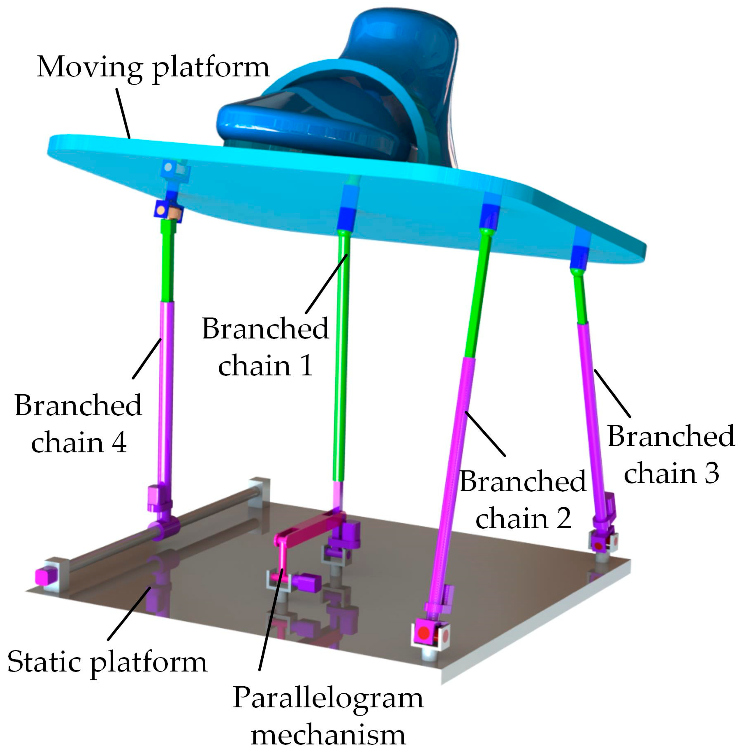
The proposed reconfigurable parallel mechanism is composed of a static platform, a moving platform, four branched chains and a parallelogram mechanism, as shown in Figure 1. Branched chain 1 is an RPS branched chain. The rotation centers of the revolute pair and spherical pair are located at the centers of the static platform and moving platform, respectively. The axis of the revolute pair is perpendicular to the axis of the cylindrical pair of branched chain 4. Branched chain 1 is connected in series with the parallelogram mechanism. When the axis of the prismatic pair in branched chain 1 is perpendicular to the plane of the static platform at all times under the action of the parallelogram mechanism, branched chain 1 is in the PS mode. Branched chains 2 and 3 are a UPS-I branched chain and a UPS-II branched chain, respectively. Their structure is the same, which is symmetrically arranged, and branched chain 3 is used as the branched chain with actuation redundancy. Branched chain 4 includes a cylindrical pair, a prismatic pair and a vA pair, and the vA pair is located at the midpoint of the side.

2.2. vA Pair Analysis

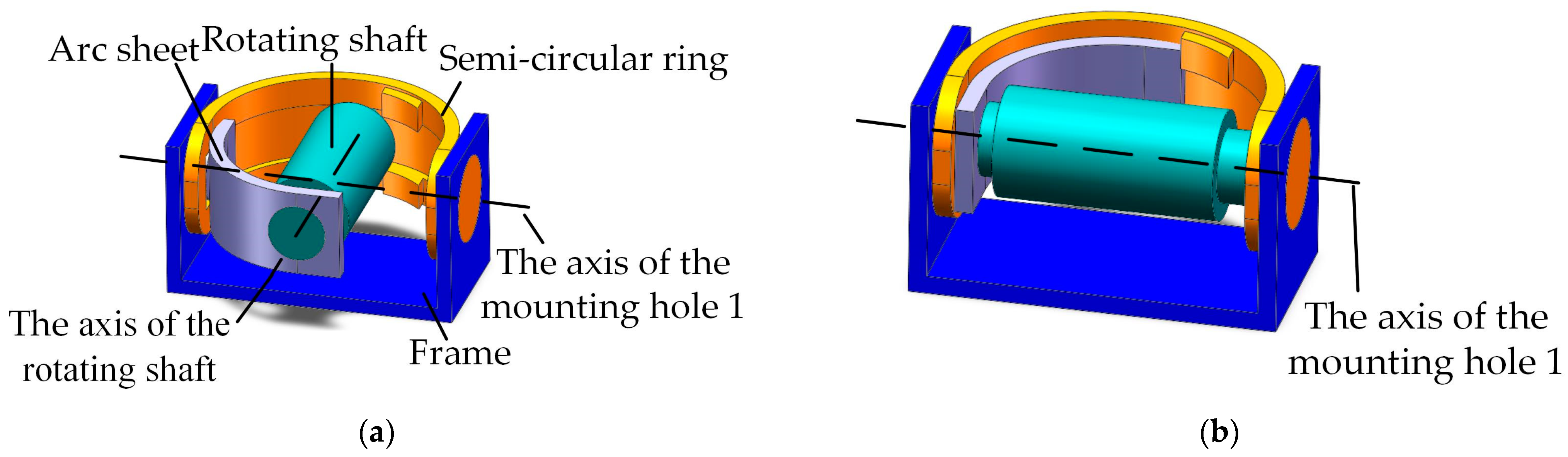
The vA pair is composed of a frame, a semi-circular ring, an arc sheet and a rotating shaft, which can be converted between the universal joint mode and the revolute-pair mode. The left and right sides of the frame are processed with mounting hole 1, and the left and right sides of the outside of the semi-circular ring are processed with mounting shaft 1. Mounting shaft 1 and mounting hole 1 are matched, and the semi-circular ring can rotate around the axis of mounting hole 1.
The inside of the semi-circular ring is processed with a groove and a limit block. One side of the arc sheet is processed with mounting hole 2, and the other side is processed with mounting shaft 2 on the outside. Mounting hole 2 is matched with the rotating shaft, and mounting shaft 2 is tangent to the top and bottom surfaces of the groove. The rotating shaft can rotate around the axis of mounting hole 2, and the arc sheet drives the rotating shaft to rotate around the axis of the semi-circular ring to change the position of the axis position of the rotating shaft.
When the rotating shaft is driven by the arc sheet to the limit position on the inner side of the semi-circular ring groove, that is, when mounting shaft 2 is tangent to the side of the groove, the axis of the rotating shaft is perpendicular to the axis of mounting hole 1, and the vA pair is in the universal joint mode, which can rotate around the axis of mounting hole 1 and the axis of the rotating shaft, as shown in Figure 2a.
When the arc sheet is in contact with the side of the limit block on the inner side of the semi-circular ring, the axis of the rotating shaft coincides with the axis of mounting hole 1, and the vA pair is in the revolute-pair mode, which can rotate around the axis of mounting hole 1, as shown in Figure 2b.

2.3. Calculation of Degree of Freedom

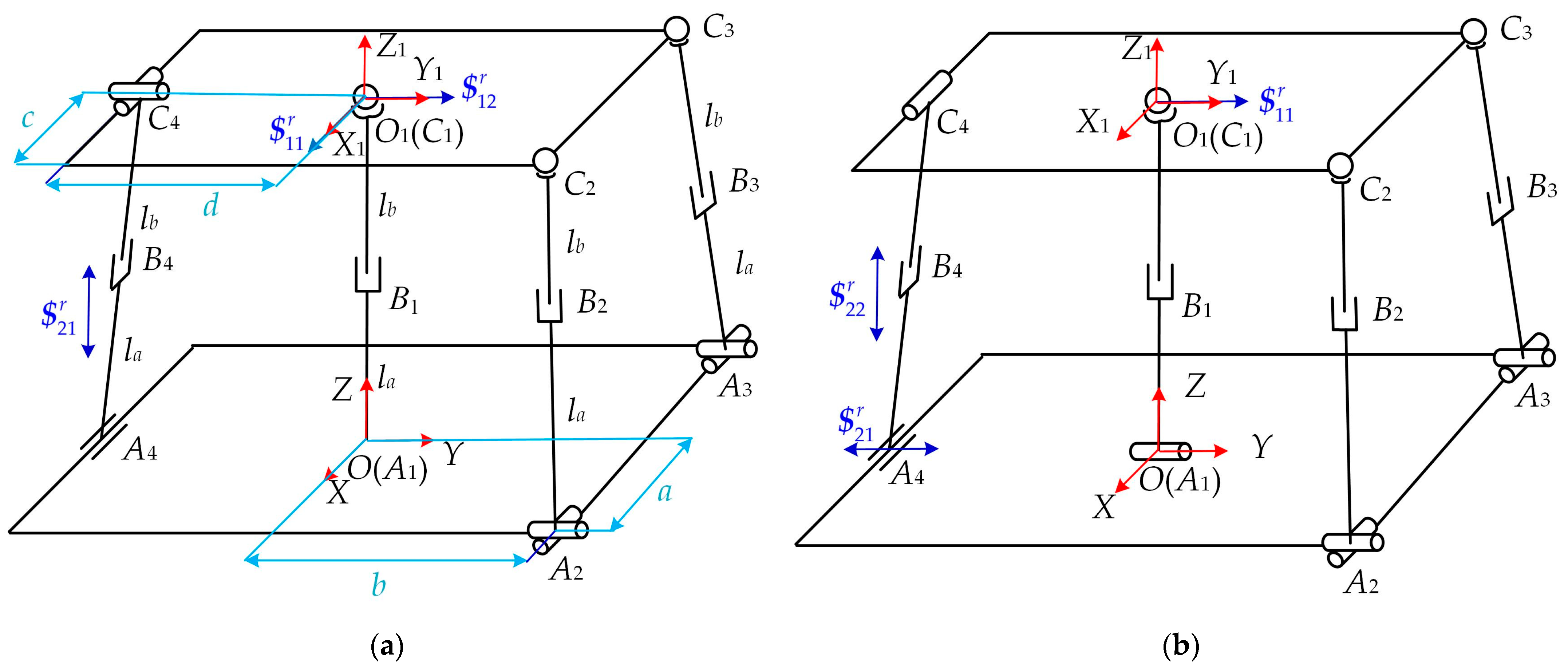
O and O1 are the center points of the static and moving platforms, respectively. Ai (i = 1, 2, 3, 4) and Ci (i = 1, 2, 3, 4) are the intersections of the kinematic pairs of each branched chain with the static platform and the moving platform, respectively. The distance between Ai (i = 2, 3) and the O point along the X-axis direction is a; the distance between Ai (i = 2, 3, 4) and the O point along the Y-axis direction is b; the distance between Ci (i = 2, 3) and the O1 point along the X1-axis direction is c; and the distance between Ci (i = 2, 3, 4) and the O1 point along the Y1-axis is d. la is the length of BiAi (i = 1, 2, 3, 4), while lb is the length of CiBi (i = 1, 2, 3, 4).
The static coordinate system is established with the center O of the static platform as the origin. The Y axis is from the O point to the midpoint of A2A3, the X axis is from the A3 point to the A2 point, and the Z axis is perpendicular to the static platform and its direction is upward. The moving coordinate system is established with the center O1 of the moving platform as the origin. The Y1 axis is from the O1 point to the midpoint of C2C3, the X1 axis is from the C3 point to the C2 point, and the Z1 axis is perpendicular to the moving platform and pointing away from the mechanism, as shown in Figure 3.
When branched chain 1 is in the PS mode and the vA pair is in the universal joint mode, the mechanism is in the 1T2R motion mode, as shown in Figure 3a; when branched chain 1 is in the RPS mode and the vA pair is in the revolute-pair mode, the mechanism is in the 2T1R motion mode, as shown in Figure 3b.
The constraint screw system is represented by the arrows shown in Table 1.

2.3.1. 1T2R Motion Mode

When branched chain 1 is in the PS mode, the kinematic screw of each kinematic pair on branched chain 1 is
$ 11 = 0 0 0 0 0 1 $ 12 = 0 1 0 e 11 0 0 $ 13 = 1 0 0 0 e 11 0 $ 14 = 0 0 1 0 0 0
The reciprocal screw of branched chain 1 in the PS mode can be obtained as
$ 11 r = 1 0 0 0 e 11 0 $ 12 r = 0 1 0 e 11 0 0
Branched chain 1 provides two constraint forces parallel to the X axis and Y axis, and both pass through the rotation center of the spherical pair, as shown in Figure 3a.
When the vA pair is in the universal joint mode, the kinematic screw of each kinematic pair on branched chain 4 is
$ 21 = 0 0 0 1 0 0 $ 22 = 1 0 0 0 0 e 12 $ 23 = 0 0 0 e 13 f 13 g 13 $ 24 = 1 0 0 0 g 14 f 14 $ 25 = 0 1 0 g 14 0 e 14
When the vA pair is in the universal joint mode, the reciprocal screw of branched chain 4 can be obtained as
$ 21 r = 0 0 0 0 0 1
In the above equations, e11, e12, g12, e13, f13, g13, e14, f14 and g14 are different real numbers.
Branched chain 4 provides a constraint couple that is parallel to the Z axis, as shown in Figure 3a.
Branched chain 2 and branched chain 3 pose no constraints on the moving platform; thus, they are not analyzed.
By combining Equations (2) and (4), the kinematic screw system of the moving platform can be obtained as
$ 1 = 1 0 0 0 e 11 0 $ 2 = 0 1 0 e 11 0 0 $ 3 = 0 0 0 0 0 1
From the kinematic screw system in Equation (5), it can be concluded that the moving platform has 1T2R degrees of freedom, which encompass two rotational degrees of freedom that bypass the origin O1 of the moving coordinate system and are parallel to the X axis and Y axis, together with one translational degree of freedom along the Z axis.
When branched chain 1 is in the PS mode and the vA pair is in the universal joint mode, the modified G-K formula is used to calculate the degree of freedom of the mechanism as follows:
M 1 = d n g 1 + i = 1 g f i + v ζ = 6 9 11 1 + 21 = 3
where d is the order of the mechanism, n is the number of mechanism links, g is the number of kinematic pairs of the mechanism, fi is the degree of freedom of the kinematic pairs of the mechanism, v is the number of parallel redundant constraints, and ζ is the number of passive degrees of freedom.
It is concluded that when branched chain 1 is in the PS mode and the vA pair is in the universal joint mode, the degree of freedom of the mechanism is 3, and the moving platform is constrained by two constraint forces and one constraint couple. The two constraint forces are parallel to the X axis and Y axis, and always intersect vertically at the center point of the moving platform, which restricts the translation of the moving platform along the X axis and Y axis. The constraint couple is parallel to the Z axis and constrains the rotation of the moving platform around the Z axis. When in motion, the positional relationship between the two constraint forces and the one constraint couple remains unchanged, and the constraint property of the moving platform does not change. Therefore, when branched chain 1 is in the PS mode and the vA pair is in the universal joint mode, the motion mode of the mechanism is 1T2R, and the degree of freedom is full-cycle.

2.3.2. 2T1R Motion Mode

When branched chain 1 is in the RPS mode, the kinematic screw of each kinematic pair on branched chain 1 is
$ 11 = 0 1 0 0 0 0 $ 12 = 0 0 0 e 21 0 f 21 $ 13 = 0 1 0 f 22 0 e 22 $ 14 = 1 0 0 0 f 22 0 $ 15 = 0 0 1 0 e 22 0
The reciprocal screw of branched chain 1 in the RPS mode can be obtained as
$ 11 r = 0 1 0 f 22 0 e 22
Branched chain 1 provides a constraint force parallel to the Y axis, which passes through the rotation center of the spherical pair, as shown in Figure 3b.
When the vA pair is in the revolute-pair mode, the kinematic screw of each kinematic pair on branched chain 4 is
$ 21 = 0 0 0 1 0 0 $ 22 = 1 0 0 0 0 e 23 $ 23 = 0 0 0 e 24 f 24 g 24 $ 24 = 1 0 0 0 g 25 f 25
When the vA pair is in the revolute-pair mode, the reciprocal screw of branched chain 4 can be obtained as
$ 21 r = 0 0 0 0 1 0 $ 22 r = 0 0 0 0 0 1
Branched chain 4 provides two constraint couples parallel to the Y axis and Z axis, as shown in Figure 3b.
In the above equations, e21, f21, e22, f22, e23, e24, f24, f25 and g25 are different real numbers.
By combining Equations (8) and (10), the kinematic screw system of the moving platform can be obtained as
$ 1 = 0 0 0 1 0 0 $ 2 = 0 0 0 0 0 1 $ 3 = 1 0 0 0 f 22 0
From the kinematic screw system in Equation (11), it can be concluded that the moving platform has 2T1R degrees of freedom, which encompass two translational degrees of freedom along the X axis and Z axis, and a rotational degree of freedom that bypasses the origin O1 of the moving coordinate system and is parallel to the X axis.
When branched chain 1 is in the RPS mode and the vA pair is in the revolute-pair mode, the modified G-K formula is used to calculate the degree of freedom of the mechanism as follows:
M 2 = d n g 1 + i = 1 g f i + v ζ = 6 10 12 1 + 21 = 3
It is concluded that when branched chain 1 is in the RPS mode and the vA pair is in the revolute-pair mode, the degree of freedom of the mechanism is 3, and the moving platform is constrained by two constraint couples and one constraint force. The two constraint couples are parallel to the Y axis and the Z axis in order to constrain the rotation of the moving platform around the Y axis and the Z axis, respectively. The constraint force that bypasses the origin O1 of the moving coordinate system and is parallel to the Y axis constrains the translation of the moving platform along the Y axis. When in motion, the positional relationship between the two constraint couples and the one constraint force remains unchanged, and the constraint property of the moving platform does not change. Therefore, when branched chain 1 is in the RPS mode and the vA pair is in the revolute-pair mode, the motion mode of the mechanism is 2T1R, and the degree of freedom is full-cycle.
Based on the above analysis, when branched chain 1 is in the PS mode and the vA pair is in the universal joint mode, the mechanism is in the 1T2R motion mode, and the degree of freedom is full-cycle. When branched chain 1 is in the RPS mode and the vA pair is in the revolute-pair mode, the mechanism is in the 2T1R motion mode, and the degree of freedom is full-cycle.
When the mechanism is in the 1T2R motion mode, the prismatic pairs of the four branched chains are used as the driving pairs. When the mechanism is in the 2T1R motion mode, the prismatic pairs of branched chains 1, 2 and 3 and the cylindrical pair of branched chain 4 are used as the driving pairs. In both motion modes, the degree of freedom of the moving platform of the mechanism is 3, and the number of driving pairs is 4, which represent a redundantly actuated parallel mechanism.

2.4. Non-Parasitic Motion Analysis

The calculation formulae for the position and orientation characteristic (POC) set of series and parallel mechanisms are as follows:
M b i = i = 1 m M J i
M P a = i = 1 v + 1 M b i
where M J i is the POC set of the i-th kinematic pair; M b i is the POC set at the end of the i-th branched chain; and M p a is the POC set of the mechanism’s moving platform.

2.4.1. Analysis of Non-Parasitic Motion of the Mechanism in the 1T2R Motion Mode

A branched chain that is composed of links and pairs in series is called a Single Opened Chain (SOC). Therefore, the topological structure of branched chain 1 is SOC1{-P11-S12-}, the topological structure of branched chains 2 and 3 is SOCi{-Ui1-Pi2-Si3-} (i = 2, 3), and the topological structure of branched chain 4 is SOC4{-C41-P42-U43-}. The center point O1 of the moving platform is selected as the reference point.
In accordance with Equation (13), the POC sets of the branched chains in the 1T2R motion mode are as follows:
M b 1 = t 1 r 3 ; M b 2 = M b 3 = t 3 r 3 ; M b 4 = t 3 r 2
where t and r represent translation and rotation, respectively, and the superscript is the number of translational/rotational motion.
In accordance with Equation (14), the POC set of the moving platform in the 1T2R motion mode is
M P a = M b 1 M b 2 M b 3 M b 4 = t 1 r 3 t 3 r 3 t 3 r 3 t 3 r 2 = t 1 r 2
The number of degrees of freedom of the mechanism is 3. Since the number of independent elements of the POC set of the moving platform is not greater than the number of degrees of freedom of the mechanism, the POC set of the moving platform can have three independent elements. It can be seen from the calculation of M p a that there is one independent translation and two independent rotations of the moving platform, and there is no non-independent parasitic motion.

2.4.2. Analysis of Non-Parasitic Motion of the Mechanism in the 2T1R Motion Mode

In the 2T1R motion mode, the topological structure of branched chain 1 is SOC1{-R11-P12-S13-}, the topological structure of branched chains 2 and 3 is SOCi{-Ui1-Pi2-Si3-} (i = 2, 3), and the topological structure of branched chain 4 is SOC4{-C41-P42-R43-}. The center point O1 of the moving platform is selected as the reference point.
In accordance with Equation (13), the POC sets of the branched chains in the 2T1R motion mode are as follows:
M b 1 = t 2 r 3 ; M b 2 = M b 3 = t 3 r 3 ; M b 4 = t 3 r 1
In accordance with Equation (14), the POC set of the moving platform in the 2T1R motion mode is
M P a = M b 1 M b 2 M b 3 M b 4 = t 2 r 3 t 3 r 3 t 3 r 3 t 3 r 1 = t 2 r 1
The number of degrees of freedom of the mechanism is 3. Since the number of independent elements of the POC set of the moving platform is not greater than the number of degrees of freedom of the mechanism, the POC set of the moving platform can have three independent elements. It can be seen from the calculation of M p a that there are two independent translations and one independent rotation of the moving platform, and there is no non-independent parasitic motion.
Based on the above analysis, when branched chain 1 is in the PS mode and the vA pair is in the universal joint mode, the mechanism is a 1T2R parallel mechanism without parasitic motion. When branched chain 1 is in the RPS mode and vA pair is in the revolute-pair mode, the mechanism is a 2T1R parallel mechanism without parasitic motion.

3. Kinematic Analysis

3.1. Inverse Position

The position vector of the moving platform center O1 in the static coordinate system O-XYZ is OO1 = [x, y, z]T, and li (i = 1, 2, 3, 4) is the length vector of each branched-chain driving pair. The attitude transformation matrix T of the moving coordinate system relative to the static coordinate system is
T = cos β sin β sin α sin β cos α 0 cos α sin α sin β cos β sin α cos β cos α
where α and β are the rotation angles of the moving platform around the X and Y axes, respectively. When branched chain 1 is in the RPS mode and the vA pair is in the revolute-pair mode, the degree of freedom of the mechanism is 2T1R, and thus, β = 0.
A i O (i = 1, 2, 3, 4) is the position vector of Ai (i = 1, 2, 3, 4) in the static coordinate system O-XYZ, and C i O 1 (i = 1, 2, 3, 4) is the position vector of Ci (i = 1, 2, 3, 4) in the moving coordinate system O1-X1Y1Z1. Their expressions are as follows:
A i O = 0 0 0 T A 2 O = a b 0 T A 3 O = a b 0 T A 4 O T C 4 O 1 b 0 T C 1 O 1 = 0 0 0 T C 2 O 1 = c d 0 T C 3 O 1 = c d 0 T C 4 O 1 = 0 d 0 T
C i O 1 (i = 1, 2, 3, 4) is transformed into the static coordinate system O-XYZ, and its expression is as follows:
C i O = T C i O 1 + O O 1 i = 1 ,   2 ,   3 ,   4
The length vector of the driving pair in branched chain i ( i = 1 ,   2 ,   3 ) can be expressed as
l i = C i O A i O i = 1 ,   2 ,   3
When the mechanism is in the 1T2R motion mode, the length vector of the driving pair in branched chain 4 can be expressed as
l 4 = C 4 O A 4 O
When the mechanism is in the 2T1R motion mode, the length vector of the driving pair in branched chain 4 can be expressed as
l 4 = X O C 4
The inverse kinematics solution of the reconfigurable parallel mechanism can be obtained by calculating the module length of the length vector l i of the driving pair in each branched chain.

3.2. Singularity Analysis

When a mechanism is in a singular configuration, the degree of freedom of the mechanism will change, which will seriously affect the performance of the mechanism. A singularity analysis of the mechanism under consideration is very important for research on parallel mechanisms.
According to the Jacobian matrix, the singular configuration of the proposed mechanism is analyzed. The relationship between the input velocity   q ˙ of the driving pair and the output velocity v of the moving platform is obtained after the derivation of the two sides of Equations (22)–(24):
J q   q ˙ = J p v
where J q is the input-velocity Jacobian matrix, and J p is the output-velocity Jacobian matrix. Their expressions are as follows:
J q = 2 l 1 0 0 0 0 2 l 2 0 0 0 0 2 l 3 0 0 0 0 2 l 4 ; J p = f 11 f 12 f 13 f 21 f 22 f 23 f 31 f 32 f 33 f 41 f 42 f 43
Since J p is a 4 × 3 matrix, it is impossible to determine whether J p is singular by judging whether the determinant of J p is 0, but it can be determined by judging whether the determinant of J P T J p is 0.
When J q is singular and J p is non-singular, that is, the determinant of J q is 0 and the determinant of J P T J p is not 0, an inverse kinematic singularity of the mechanism occurs.
When J p is singular and J q is non-singular, that is, the determinant of J q is not 0 and the determinant of J P T J p is 0, a forward kinematic singularity of the mechanism occurs.
When both J p and J q are singular, a combined singularity occurs.
If the determinant of J q is not 0, then Equation (25) can be written as
  q ˙ = Jv = J q 1 J p v
where J is the mechanism Jacobian matrix.

3.2.1. Singularity Analysis in the 1T2R Motion Mode

The length of each branched-chain driving pair cannot be zero in practical applications; thus, there is no inverse kinematic singularity in the mechanism.
When f22 = f23, f32 = f33 and f42 = f43 are established at the same time, det J P T J p = 0 , and the mechanism exhibits forward kinematic singularity. The calculation shows that this situation is contradictory to the hypothesis, so there is no forward kinematic singularity in the mechanism.
Since the length of the driving pair is not zero and det J q = 0 , there is no combined singularity in the mechanism.

3.2.2. Singularity Analysis in the 2T1R Motion Mode

When X = 0, the length of the driving pair of branched chain 4 is zero, det J q = 0 , the inverse kinematic singularity of the mechanism occurs, and the RPS branched chain is perpendicular to the static platform, as shown in Figure 4. When the above singular position occurs, the parallelogram mechanism can be started to produce action; thus, the position relationship between the RPS branched chain and the static platform changes to avoid the occurrence of inverse kinematic singularity.
When X = a , α = 0 , and a = c ; X = b , α = 0 , and a = b = c ; X = c , α = 0 , and a = c ; or X = d , α = 0 , and a = d = c , det J P T J p = 0 , and the forward kinematic singularity of the mechanism occurs. Therefore, when selecting the structural parameters of the mechanism, a c should be fulfilled to avoid the forward kinematic singularity of the mechanism.
When X = 0 , det J q = 0 , which is contradictory to the condition of forward kinematic singularity; thus, there is no combined singularity in the mechanism.

4. Performance Analysis

4.1. Performance Index

The main movements of the ankle joint are plantar flexion/dorsiflexion and eversion/inversion movements. The range of motions of the ankle joint is shown in Table 2 [8]. The initial dimension parameters of the mechanism are as follows: a = 180 mm, b = 120 mm, c = 80 mm, d = 100 mm, la = 180 mm and lb = 180 mm. In the 1T2R motion mode, the mechanism carries out the training of ankle joint activity. According to Table 2, the search space of the mechanism is α ∈ (−40°, 24°), β ∈ (−18°, 18°), and Z ∈ (250 mm, 350 mm). In the 2T1R motion mode, the mechanism carries out ankle joint proprioception training. According to Table 2, the search space of the mechanism is α ∈ (−18°, 18°), X ∈ (−75 mm, 75 mm), and Z ∈ (194 mm, 320 mm).
It is assumed that the number of points in the search space is W. While solving the workspace of the mechanism, the number of points in the reachable workspace is Wi. Then, the performance index WV of the reachable workspace is as follows:
W V = W i W
Dexterity is an important index to evaluate the kinematic performance of the mechanism. The reciprocal of the condition number of the Jacobian matrix is used to analyze the dexterity index of the mechanism. The range of the condition number of the Jacobian matrix is 1 to ∞; thus, the range of the dexterity index is 0 to 1 [31]. The greater the dexterity index, the better the motion transmission performance of the mechanism.
To evaluate the dexterity of the mechanism in the 1T2R motion mode, the mechanism Jacobian matrix J is divided into the translational Jacobian matrix J v and the rotational Jacobian matrix J ω , and then the translational dexterity and the rotational dexterity of the mechanism are analyzed, respectively, as follows:
L C I v = 1 cond ( J v ) = σ min ( J v ) σ max ( J v )
L C I ω = 1 cond ( J ω ) = σ min ( J ω ) σ max ( J ω )
The level of the load capacity is related to whether the mechanism can achieve the expected load goal. The relationship between the force or moment vector F acting on the moving platform and the driving force f of the driving pair can be expressed as
F = Gf
where the matrix G is the force Jacobian matrix of the mechanism, with G = J T .
F max represents the maximum load capacity at the limit of the mechanism when the modulus of the driving force vector f is unit 1. In the 2T1R motion mode, F max is used to evaluate the load capacity performance of the mechanism. The larger the value, the better the load capacity performance of the mechanism. Its expression is as follows:
F max = λ max G T G

4.2. Workspace and Dexterity Performance Index in the 1T2R Motion Mode

When the mechanism is a redundantly actuated parallel mechanism, the prismatic pairs of branched chains 1, 2, 3 and 4 are the driving pairs of the mechanism; when the mechanism is a non-redundantly actuated parallel mechanism, the prismatic pairs of branched chains 1, 2 and 4 are the driving pairs of the mechanism. In the 1T2R motion mode, the workspace performance index of the redundantly actuated parallel mechanism is 0.6126, and the workspace performance index of the non-redundantly actuated parallel mechanism is 0.6126. After introducing branched chains with actuation redundancy, the size and shape of the reachable workspace of the mechanism have not changed, as shown in Figure 5.
It is calculated that the translational dexterity of the redundantly actuated parallel mechanism and the non-redundantly actuated parallel mechanism is always 1, indicating that the mechanism has complete dexterity in the translational degree of freedom and can meet the needs of flexible translation.
The region with a low rotational dexterity performance is represented as a blue region. By comparing Figure 5a,b, it can be concluded that after introducing branched chains with actuation redundancy, the rotational dexterity performance index represented by the blue region of the redundantly actuated parallel mechanism is significantly higher than that of the non-redundantly actuated parallel mechanism, and the rotational dexterity performance of the mechanism is significantly improved. The region with a high rotational dexterity performance is represented as a yellow region. As the α value increases, the rotational dexterity performance gradually decreases, which is reflected in the transition from yellow to green and blue.
Under the initial parameters at Z = 300 mm, the distribution of the rotational dexterity index of the redundantly actuated parallel mechanism and non-redundantly actuated parallel mechanism is obtained, as shown in Figure 6. It can be seen from Figure 6 that the rotational dexterity index of the redundantly actuated parallel mechanism is higher than that of the non-redundantly actuated parallel mechanism. The rotational dexterity index of the redundantly actuated parallel mechanism is symmetrically distributed with respect to β = 0°. As the α value increases, the rotational dexterity performance gradually decreases.

4.3. Workspace and Load Capacity Performance Index in the 2T1R Motion Mode

When the mechanism is a redundantly actuated parallel mechanism, the prismatic pairs of branched chains 1, 2 and 3 and the cylindrical pair of branched chain 4 are the driving pairs of the mechanism; when the mechanism is a non-redundantly actuated parallel mechanism, the prismatic pairs of branched chains 1 and 2 and the cylindrical pair of branched chain 4 are the driving pairs of the mechanism. According to the calculation, it can be concluded that in the 2T1R motion mode, the workspace performance index of the redundantly actuated parallel mechanism is 0.9619, and the workspace performance index of the non-redundantly actuated parallel mechanism is 0.9619. After introducing branched chains with actuation redundancy, the size and shape of the reachable workspace of the mechanism have not changed, as shown in Figure 7.
The region with a low load capacity performance is represented as a blue region. By comparing Figure 7a,b, it can be concluded that after introducing branched chains with actuation redundancy, the load capacity performance index represented by the blue region of the redundantly actuated parallel mechanism is significantly higher than that of the non-redundantly actuated parallel mechanism, and the load capacity performance of the mechanism is clearly improved. The region with a high load capacity performance is represented as a yellow region. With an increase in the α value, the load capacity performance of the redundantly actuated parallel mechanism increases first and then decreases, which is reflected in the transition from green to yellow, green and blue.
Under the initial parameters when α = 0°, the load capacity performance distribution of the redundantly actuated parallel mechanism and non-redundantly actuated parallel mechanism is obtained, as shown in Figure 8. When comparing Figure 8a,b, it can be concluded that the load capacity performance of the redundantly actuated parallel mechanism is significantly higher than that of the non-redundantly actuated parallel mechanism. From Figure 8a, it can be concluded that the load capacity performance of the redundantly actuated parallel mechanism is symmetrical when X = 0 mm. As the Z value increases, the load capacity performance gradually increases. From Figure 8b, it can be concluded that with an increase in the X value and Z value, the load capacity performance of the non-redundantly actuated parallel mechanism increases gradually.

5. Optimization Design

5.1. Mathematical Modeling

5.1.1. Design Variables

Among all the dimension parameters, a, b, c, d, la and lb have an impact on each performance index. Therefore, the dimension parameters a, b, c, d, la and lb are taken as the design variables in the optimization design.
The initial value and constraint range of each design variable of the reconfigurable parallel mechanism are presented in Table 3.

5.1.2. Objective Function

The performance indexes defined in Equations (30) and (32) only reflect the performance indexes of the mechanism at a certain point in the reachable workspace and cannot be used to evaluate the performance indexes of the parallel mechanism in the whole reachable workspace. Therefore, the following global performance index is defined for the reachable workspace of the parallel mechanism:
G C I ω = i = 1 W i L C I ω W i
F W max = i = 1 W i F max W i
For parallel mechanisms, under the premise of meeting the design requirements, it is usually desirable to obtain the optimal working performance under the maximization of the reachable workspace. To obtain the reachable workspace performance index in the two motion modes proposed in Equations (28), (33) and (34), the global rotational dexterity index in the 1T2R motion mode, and the global load capacity performance index in the 2T1R motion mode, the four objective functions can be transformed into a single objective function by using the reference target distance method. This method is similar to the codirectional processing of multiple targets, and its application is simple but extensive. Using this method, the objective function can be defined as
F x = 1 4 i = 1 4 Z i f i X
where Zi is the reference value of the objective function.

5.2. Optimization Example

The parameters of the particle swarm algorithm are shown in Table 4. Through the iterative calculation of the objective function, the variation curve of the objective function value with iteration times is obtained and shown in Figure 9. The optimization results of the dimension parameters of the mechanism are shown in Table 5, and the optimization results of the performance index of the mechanism are shown in Table 6.
It can be seen from Figure 9 that the algorithm converges is faster and the curve is steep. As the iteration times gradually increases, the objective function value gradually tends to a fixed value. After about 57 iterations, the objective function value F tends to be stable and the optimization result reaches the best.
It can be seen from Table 4 and Table 5 that after using the particle swarm algorithm to optimize the reconfigurable parallel mechanism, the dimension parameters b, c, d and lb have increased, while the dimension parameters a and la have decreased. It is calculated that, in the 1T2R motion mode, the workspace index of the mechanism has increased by 39.60%, and the rotational dexterity index has increased by 20.17%. In the 2T1R motion mode, the workspace index of the mechanism has increased by 1.31%, and the load capacity index has increased by 60.88%. These results could provide a reference for the design of mechanism dimension parameters.

5.3. Comparison of Results

Since the accuracy and manufacturing cost of the mechanism will be limited in actual processing, the optimized dimension parameters are rounded to obtain a new set of dimension parameters, wherein a = 155 mm, b = 155 mm, c = 150 mm, d = 150 mm, la = 175 mm and lb = 235 mm, and the performance index of the mechanism is recalculated according to these parameters.
By comparing Figure 5a and Figure 10a, it is evident that in the 1T2R motion mode, the reachable workspace of the mechanism increases compared to that before optimization. In the reachable workspace, the rotational dexterity index is greater than 0.7434, and the workspace index and rotational dexterity index of the mechanism are significantly improved compared to those before optimization. By comparing Figure 7a and Figure 10b, it is evident that the reachable workspace of the mechanism in the 2T1R motion mode increases compared to that before optimization. In the reachable workspace, the maximum load capacity performance index of the mechanism is greater than 177.8003, and the workspace and load capacity performance index of the mechanism are improved compared to those before optimization.
When comparing Figure 6a and Figure 10c in the 1T2R motion mode at the same value of Z = 300 mm, it can be seen that the rotational dexterity index in the whole plane is greater than 0.7584. Compared to before optimization, the area of the yellow region increases, the rotational dexterity performance index represented by the blue region increases, and the gap between the rotational dexterity performance index represented by the blue region and the rotational dexterity performance index represented by the yellow region is reduced. With a change in the α value, the change in the rotational dexterity performance is gentle compared to that before optimization. In the 2T1R motion mode, α is taken to be 0°. When comparing Figure 8a and Figure 10d, it can be seen that the load capacity performance index in the whole plane is greater than 197.7812. Compared to before optimization, the gap between the load capacity performance index represented by the blue region and the load capacity performance index represented by the yellow region is reduced. As the Z value changes, the load capacity performance index changes more gently than before optimization.

6. Conclusions

A new type of reconfigurable parallel ankle rehabilitation mechanism is proposed. The mechanism can be converted between the 1T2R and 2T1R motion modes to meet the requirements of ankle joint activity and proprioception training.
In these two motion modes, the mechanism has full-cycle degrees of freedom and exhibits no parasitic motion, which can prevent secondary damage to patients. The singularity of the mechanism can be avoided by incorporating a parallelogram mechanism and selecting appropriate dimension parameters.
Using branched chains with actuation redundancy can improve the rotational dexterity and load capacity performance index, without affecting the workspace index. Compared to the original mechanism, the optimized mechanism has better dexterity and load capacity performance index and more uniform distribution than before optimization.

Author Contributions

Conceptualization, L.Z.; methodology, L.Z. and R.L.; validation, L.Z., F.N. and C.C.; writing—original draft preparation, L.Z., R.L. and Z.J.; writing—review and editing, L.Z. and R.L.; supervision, R.L.; funding acquisition, R.L. and F.N. All authors have read and agreed to the published version of the manuscript.

Funding

This research was funded by the Key Research and Development Program of Shanxi Province of China, grant numbers 202202150401018 and 201903D421051, and was also supported by the Opening Foundation of Shanxi Key Laboratory of Advanced Manufacturing Technology, grant number XJZZ202105.

Institutional Review Board Statement

Not applicable.

Informed Consent Statement

Not applicable.

Data Availability Statement

The raw data supporting the conclusions of this article will be made available by the authors on request.

Conflicts of Interest

The authors declare no conflicts of interest.

References

  1. Herzog, M.M.; Kerr, Z.Y.; Marshall, S.W.; Wikstrom, E.A. Epidemiology of ankle sprains and chronic ankle instability. J. Athl. Train. 2019, 54, 603–610. [Google Scholar] [CrossRef]
  2. Steinberg, N.; Adams, R.; Tirosh, O.; Karin, J.; Waddington, G. Effects of textured balance board training in adolescent ballet dancers with ankle pathology. J. Sport Rehabil. 2019, 28, 584–592. [Google Scholar] [CrossRef]
  3. Zuo, S.P.; Li, J.F.; Dong, M.J.; Zhou, X.D.; Fan, W.P.; Kong, Y. Design and performance evaluation of a novel wearable parallel mechanism for ankle rehabilitation. Front. Neurorobot. 2020, 14, 9. [Google Scholar] [CrossRef]
  4. Liao, Z.W.; Yao, L.G.; Lu, Z.X.; Zhang, J. Screw theory based mathematical modeling and kinematic analysis of a novel ankle rehabilitation robot with a constrained 3-PSP mechanism topology. Int. J. Intell. Robot. Appl. 2018, 2, 351–360. [Google Scholar] [CrossRef]
  5. Zou, Y.P.; Zhang, A.D.; Zhang, Q.; Zhang, B.L.; Wu, X.S.; Qin, T. Design and experimental research of 3-RRS parallel ankle rehabilitation robot. Micromachines 2022, 13, 950. [Google Scholar] [CrossRef]
  6. Russo, M.; Ceccarelli, M. Analysis of a wearable robotic system for ankle rehabilitation. Machines 2020, 8, 48. [Google Scholar] [CrossRef]
  7. Jamwal, P.K.; Hussain, S.; Xie, S.Q. Three-Stage design analysis and multicriteria optimization of a parallel ankle rehabilitation robot using genetic algorithm. IEEE Trans. Autom. Sci. Eng. 2015, 12, 1433–1446. [Google Scholar] [CrossRef]
  8. Zeng, D.X.; Wu, H.F.; Zhao, X.H.; Lu, J.W.; Luo, X.L. A new type of ankle-foot rehabilitation robot based on muscle motor characteristics. IEEE Trans. Autom. Sci. Eng. 2020, 8, 215915–215927. [Google Scholar] [CrossRef]
  9. Liu, Y.; Lu, W.J.; Wu, H.F.; Xia, Y.C.; Hu, B.; Zeng, D.X. Performance analysis and trajectory planning of multi-locomotion mode ankle rehabilitation robot. Robot. Auton. Syst. 2022, 157, 104246. [Google Scholar] [CrossRef]
  10. Zhang, M.M.; Cao, J.H.; Zhu, G.L.; Miao, Q.; Zeng, X.F.; Xie, S.Q. Reconfigurable workspace and torque capacity of a compliant ankle rehabilitation robot (CARR). Robot. Auton. Syst. 2017, 98, 213–221. [Google Scholar] [CrossRef]
  11. Ye, W.; Chai, X.X.; Zhang, K.T. Kinematic modeling and optimization of a new reconfigurable parallel mechanism. Mech. Mach. Theory 2020, 149, 103850. [Google Scholar] [CrossRef]
  12. Hu, X.Y.; Liu, H.Z. Design and analysis of full-configuration decoupled actuating reconfigurable parallel spherical joint. J. Mech. Sci. Technol. 2022, 36, 933–945. [Google Scholar] [CrossRef]
  13. Tian, C.X.; Zhang, D. Design and analysis of novel kinematically redundant reconfigurable generalized parallel manipulators. Mech. Mach. Theory 2021, 166, 104481. [Google Scholar] [CrossRef]
  14. Chablat, D.; Kong, X.W.; Zhang, C.W. Kinematics, workspace, and singularity analysis of a parallel robot with five operation modes. J. Mech. Robot. 2018, 10, 035001. [Google Scholar] [CrossRef]
  15. Wu, G.L.; Bai, S.P. Design and kinematic analysis of a 3-RRR spherical parallel manipulator reconfigured with four-bar linkages. Robot. Comput. Integr. Manuf. 2019, 56, 55–65. [Google Scholar] [CrossRef]
  16. Huang, G.Y.; Zhang, D.; Zou, Q.; Ye, W.; Kong, L.Y. Analysis and design method of a class of reconfigurable parallel mechanisms by using reconfigurable platform. Mech. Mach. Theory 2023, 181, 105215. [Google Scholar] [CrossRef]
  17. Gan, D.M.; Dias, J.; Seneviratne, L. Unified kinematics and optimal design of a 3rRPS metamorphic parallel mechanism with a reconfigurable revolute joint. Mech. Mach. Theory 2016, 96, 239–254. [Google Scholar] [CrossRef]
  18. Liu, J.F.; Fan, X.M.; Ding, H.F. Investigation of a novel 2R1T parallel mechanism and construction of its variants. Robotica 2021, 39, 1834–1848. [Google Scholar] [CrossRef]
  19. Chen, M.; Zhang, Q.; Qin, X.R.; Sun, Y.T. Kinematic, dynamic, and performance analysis of a new 3-DOF over-constrained parallel mechanism without parasitic motion. Mech. Mach. Theory 2021, 162, 104365. [Google Scholar] [CrossRef]
  20. Nayak, A.; Caro, S.; Wenger, P. Comparison of 3-[PP]S parallel manipulators based on their singularity free orientation workspace, parasitic motions and complexity. Mech. Mach. Theory 2018, 129, 293–315. [Google Scholar] [CrossRef]
  21. Nigatu, H.; Kim, D. Optimization of 3-DoF manipulators’ parasitic motion with the instantaneous restriction space-based analytic coupling relation. Appl. Sci. 2021, 11, 4690. [Google Scholar] [CrossRef]
  22. Shen, H.P.; Tang, Y.; Wu, G.L.; Li, J.; Li, T.; Yang, T.L. Design and analysis of a class of two-limb non-parasitic 2T1R parallel mechanism with decoupled motion and symbolic forward position solution—Influence of optimal arrangement of limbs onto the kinematics, dynamics and stiffness. Mech. Mach. Theory 2022, 172, 104815. [Google Scholar] [CrossRef]
  23. Wang, C.Z.; Fang, Y.F.; Guo, S.; Zhou, C.C. Design and kinematic analysis of redundantly actuated parallel mechanisms for ankle rehabilitation. Robotica 2015, 33, 366–384. [Google Scholar] [CrossRef]
  24. Wu, X.Y. Performance analysis and optimum design of a redundant planar parallel manipulator. Symmetry 2019, 11, 908. [Google Scholar] [CrossRef]
  25. Wang, H.; Li, W.; Liu, H.T.; Zhang, J.X.; Liu, S.T. Conceptual design and dimensional synthesis of a novel parallel mechanism for lower-limb rehabilitation. Robotica 2019, 37, 469–480. [Google Scholar] [CrossRef]
  26. Zhang, D.S.; Xu, Y.D.; Yao, J.T.; Hu, B.; Zhao, Y.S. Kinematics, dynamics and stiffness analysis of a novel 3-DOF kinematically/actuation redundant planar parallel mechanism. Mech. Mach. Theory 2017, 116, 203–219. [Google Scholar] [CrossRef]
  27. Xu, L.M.; Li, Q.C.; Zhang, N.B.; Chen, Q.H. Mobility, kinematic analysis, and dimensional optimization of new three-degrees-of-freedom parallel manipulator with actuation redundancy. J. Mech. Robot. 2017, 9, 041008. [Google Scholar] [CrossRef]
  28. Xu, L.M.; Chai, X.X.; Li, Q.C.; Zhang, L.A.; Ye, W. Design and experimental investigation of a new 2R1T overconstrained parallel kinematic machine with actuation redundancy. J. Mech. Robot. 2019, 11, 031016. [Google Scholar] [CrossRef]
  29. Fang, H.L.; Tang, T.F.; Zhang, J. Kinematic analysis and comparison of a 2R1T redundantly actuated parallel manipulator and its non-redundantly actuated forms. Mech. Mach. Theory 2019, 142, 103587. [Google Scholar] [CrossRef]
  30. Wang, Y.J.; Belzile, B.; Angeles, J.; Li, Q.C. Kinematic analysis and optimum design of a novel 2PUR-2RPU parallel robot. Mech. Mach. Theory 2019, 139, 407–423. [Google Scholar] [CrossRef]
  31. Feller, D. Dexterity, workspace and performance analysis of the conceptual design of a novel three-legged, redundant, lightweight, compliant, serial-parallel robot. J. Intell. Robot. Syst. 2023, 109, 6. [Google Scholar] [CrossRef]
Figure 1. Reconfigurable parallel mechanism.
Applsci 14 01757 g001
Figure 2. Two modes of vA pair: (a) universal joint mode and (b) revolute-pair mode.
Applsci 14 01757 g002
Figure 3. Structural diagram and constraint screw system of the mechanism: (a) 1T2R motion mode, and (b) 2T1R motion mode.
Applsci 14 01757 g003
Figure 4. Singularity configuration of the mechanism in the 2T1R motion mode.
Applsci 14 01757 g004
Figure 5. The rotational dexterity index distribution in the workspace: (a) a redundantly actuated parallel mechanism and (b) a non-redundantly actuated parallel mechanism.
Applsci 14 01757 g005
Figure 6. The three-dimensional distribution map and corresponding contour lines of rotational dexterity index at Z = 300 mm: (a) redundantly actuated parallel mechanism and (b) non-redundantly actuated parallel mechanism.
Applsci 14 01757 g006
Figure 7. The load capacity performance index distribution in the workspace: (a) a redundantly actuated parallel mechanism and (b) a non-redundantly actuated parallel mechanism.
Applsci 14 01757 g007
Figure 8. The three-dimensional distribution map and corresponding contour lines of load capacity performance index at α = 0°: (a) redundantly actuated parallel mechanism and (b) non-redundantly actuated parallel mechanism.
Applsci 14 01757 g008
Figure 9. Variation in the objective function value with iteration times.
Applsci 14 01757 g009
Figure 10. Performance index after optimization. (a) The rotational dexterity index distribution in the workspace (after optimization); (b) the load capacity performance index distribution in the workspace (after optimization); (c) the three-dimensional distribution map and corresponding contour lines of the rotational dexterity index at Z = 300 mm (after optimization); and (d) the three-dimensional distribution map and corresponding contour lines of the load capacity performance index at α = 0° (after optimization).
Applsci 14 01757 g010aApplsci 14 01757 g010b
Table 1. Types and meanings of arrows adopted.
Arrow ElementPhysical Meanings
Applsci 14 01757 i001Constraint force
Applsci 14 01757 i002Constraint couple
Table 2. Allowable range of motions of ankle joint.
Type of MotionRange of Motions
Dorsiflexion24.68 ± 3.25°
Plantar flexion40.92 ± 4.32°
Inversion16.29 ± 3.88°
Eversion15.87 ± 4.45°
Table 3. The initial value and constraint range of the design variables.
Design VariableInitial ValueConstraint Range
a (mm)180(100, 200)
b (mm)120(50, 200)
c (mm)80(50, 150)
d (mm)100(50, 150)
la (mm)180(150, 300)
lb (mm)180(150, 300)
Table 4. Parameters of the particle swarm algorithm.
ParameterValue
Population size50
Iteration times80
Personal learning coefficient1.8
Social learning coefficient2.0
Weight coefficient0.9
Table 5. Optimization results of the dimension parameters.
Dimension ParameterBefore OptimizationAfter Optimization
a (mm)180155.2789
b (mm)120154.9881
c (mm)80147.8838
d (mm)100149.9985
la (mm)180174.9823
lb (mm)180235.0947
Table 6. Optimization results of the performance index.
Motion ModePerformance IndexBefore OptimizationAfter Optimization
1T2RWorkspace index0.61260.8552
Rotational dexterity index0.78000.9373
2T1RWorkspace index0.96190.9745
Load capacity index127.5462205.1983
Disclaimer/Publisher’s Note: The statements, opinions and data contained in all publications are solely those of the individual author(s) and contributor(s) and not of MDPI and/or the editor(s). MDPI and/or the editor(s) disclaim responsibility for any injury to people or property resulting from any ideas, methods, instructions or products referred to in the content.

