Abstract
The efficacy of alumina-sol based coatings in a water-free atmosphere at high temperatures suggests a potential solution for enhancing the corrosion resistance of high-alloyed steels in Carbon Capture and Storage (CCS) environments. In this study, coupons of X20Cr13, designed for use as injection pipes with 13% Chromium and 0.20% Carbon (1.4021, AISI 420), were sol-gel coated with water and ethanol-based alumina. These coated coupons were then exposed to CO2-saturated saline aquifer water, simulating conditions in the Northern German Basin, for 1000 h at ambient pressure and 60 °C. Corrosion fatigue experiments were also conducted using specimens of X5CrNiMoCuNb16-4 (1.4542, AISI 630), a suitable candidate for geothermal applications, to assess the impact of the ethanol-based coating on the number of cycles to failure at different stress amplitudes. Unfortunately, the coating exhibited early spallation, resulting in corrosion kinetics and corrosion fatigue data identical to those of uncoated specimens. Consequently, the initially promising Boehmit coating is deemed unsuitable for CCS applications and further research therefore not advisable.
Keywords:
alumina coating; high alloyed steel; pitting; surface corrosion; CO2; pipeline; corrosion; CCS; CO2-storage 1. Introduction
Addressing global warming, one of society’s significant challenges, involves mitigating the emission of the greenhouse gas CO2, primarily originating from power plants. A proposed solution is Carbon Capture and Storage (CCS), a process comprising three key stages: the capture and compression of CO2 and emission gases directly from combustion processes at the source (such as coal power plants), the transmission through pipelines, and the injection into suitable geological formations [1,2]. During this process, CO2 is pressurized to a supercritical (or liquid) state [3,4].
Hence, a key area of research focuses on understanding the corrosion behavior of steels in supercritical CO2 [5] or CO2-saturated saline aquifer waters [6]. In the process of injecting CO2 into deep geological saline aquifer reservoirs, as observed in the Northern German Basin [7,8,9], the dissolved CO2 in the aquifer water creates a highly corrosive environment that can lead to the failure of pipe steels [10,11].
The general corrosion process is explained as follows: An FeCO3 corrosion layer (siderite) forms on the alloy surface due to the anodic dissolution of iron from the pipe steel [10,12]. In a CO2-rich environment, simultaneous anodic and cathodic reactions result in the formation of corrosion products that precipitate on the steel surface. These products mainly consist of FeCO3 (siderite), Fe(HCO3)2 (iron bicarbonate), and FeOOH (goethite) [10,13].
Corrosion processes in Carbon Capture and Storage (CCS) environments are significantly influenced various environmental factors, including the composition of the surrounding media and alloy, temperature, CO2 partial pressure, flow conditions, contaminations, dissolved salts and the formation of protective scales [10,11,12,13,14,15,16,17,18,19,20,21,22] Although high-alloyed steel generally exhibits good corrosion resistance, corrosion in the injection pipe can occur in CO2-rich aquifer water, particularly if phase boundaries form during intermissions of the injection process when the aquifer water flows back into the pipe [13,14,15].
1.4021 is a widely used martensitic stainless steel in industry, featuring 13% Cr and 0.20% C. Another notable stainless steel, 1.4542 (AISI 630, X5CrNiCuNb16-4), is a precipitation hardening martensitic variant with approximately 3% small copper particles distributed in the matrix for enhanced precipitation hardening [23,24]. Research indicates a direct correlation between the mechanical and corrosion properties of various steel types and their surface conditions resulting from machining processes [25,26,27,28,29]. Generally, corrosion resistance improves with reduced surface depth on carbon steel [26], austenitic stainless steel [28] after shot peening [29], and ferritic stainless steel when Ra exceeds 0.5 µm [28]. Interestingly, the impact of relative humidity on internal pipeline corrosion is more significant than that of initial surface roughness; reducing humidity proves more effective than altering initial surface conditions [27].
Smooth surfaces and compressive surface stress have a positive correlation with improved fatigue behavior in air under corrosive environments. This relationship extends to enhanced corrosion resistance, leading to improved corrosion fatigue behavior as well [30,31,32,33].
To ensure the required longevity of pipes utilized in Carbon Capture and Storage (CCS) technology, employing protective coatings composed of heat-resistant ceramics is a viable technical solution [34,35]. Alumina coatings emerge as promising choices owing to their high inertness and stability at elevated temperatures [36,37]. Various methods, such as plasma spraying, chemical vapor deposition, and ceramic slurry application, are employed to produce thick alumina coatings, while the sol-gel technique allows for the application of thin alumina coatings [34,35,38,39]. Alumina has demonstrated resilience in high-temperature environments and can be effectively applied as a coating through the sol-gel method [34,36,40,41,42,43]. However, despite these benefits it is important to note that this type of coating has great impact in terms of rising costs, more complicated manufacturing and implication in the supply chain.
Research by Dressler et al. [44] showcased the efficacy of a sol-gel alumina layer, generated via a modified Yoldas sol [41], in providing effective protection for Inconel-718 even after 4000 h of exposure at 800 °C in static laboratory air. Additionally, a 400 nm thick transition alumina layer, applied using the sol-gel method on commercial power plant steel X20, exhibited excellent protection against oxidation in laboratory air up to 650 °C [35]. The infusion of manganese and chromium ions into the alumina layer, leading to the formation of mixed oxides, contributes to the enhanced protective properties of the coating, preventing oxidation. Furthermore, the avoidance of local defects, attributed to substrate preparation through polishing, is identified as a significant factor in improving the coating process [34,35].
Enhancing the corrosion fatigue behavior of coated steels involves achieving high resistance to cracking, low porosity in the coating [45], and inducing compressive residual stresses within the substrate surface [30,46].
Schmitt-Thomas et al. [47] observed that anodic coatings generally improved the corrosion fatigue behavior of X20Cr13, offering cathodic protection in case of coating breakdown. No corrosion occurred in the substrate when using coatings less noble than the steel, as anodic dissolution took place in the coatings [47,48]. Alumina coating provided cathodic protection for both X20Cr13 and X5CrNiCuNb16-4. Oliveira et al. [48] noted that the fatigue behavior of AISI4043 (36CrNiMo4), a medium carbon, low alloy steel, remains similar to that in air. Fatigue cracks initiated at alumina particles in the substrate steel rather than corrosion pits formed during testing. The corrosion fatigue strength of ceramic-sprayed medium carbon steel (S45C) was slightly higher than that of the substrate steel at medium stress levels, but the coating’s sealing nature had little effect on improving corrosion fatigue strength at higher stress levels. Once coating cracks formed, corrosion fatigue strength became equivalent to that of the substrate steel. Voorwald et al. [46] indicated that tungsten carbide WC–17Co and WC–10Co–4Cr thermal spray coatings applied by high velocity oxygen fuel coating (HVOF) process result in higher fatigue strength. In contrast, the fatigue strength of AISI 4340 steel associated with chromium electroplating was significantly reduced.
The study introduces the prospect of reducing corrosion rates and pit initiation by applying an alumina coating via the sol-gel process to coupons of 1.4021 and fatigue specimens of 1.4542. However, experiments indicate that this approach is not favorable in a CCS environment. Nonetheless, the results provide valuable insights into corrosion management during carbon compression.
2. Materials and Methods
Immersive tests were conducted under ambient pressure using coupons measuring 50 mm × 20 mm × 4 mm, fabricated from high-alloyed martensitic stainless steel 1.4021 (X20Cr13, AISI 420). Corrosion fatigue tests were carried out using high-alloyed martensitic corrosion resistant stainless steel 1.4542 (X5CrNiCuNb16-4, AISI 630, PRE number 15.0–18.9 (PREN = %Cr + 3.3% Mo + 16% N) [49,50]). The chemical composition was analyzed using spark emission spectrometry (SPEKTROLAB M) and the Electron Probe Microanalyzer JXA8900-RLn (Table 1).

Table 1.
Chemical composition of 1.4542 (X5CrNiCuNb16-4, AISI 630) and 1.4021 (X20Cr13, AISI 420) (in mass percent).
The microstructure of alloy 1.4542, revealed through etching before exposure and fatigue testing, displays martensite with varying needle-shaped sizes and a minor percentage of delta phase precipitation.
For the preparation of water and ethanol-based sols and coatings, the procedures outlined in [34,35,43,44,51,52,53], and illustrated in [34] were followed. Initially, an aluminum nitrate (V) solution was heated to 87 °C, and aluminum tri-sec-butylate dissolved in secbutanole was added under vigorous stirring for up to 1 h. After cooling to room temperature, the sol was directly used for the dip-coating process. The preparation of aqueous modified Yoldas sols followed the method described in [51,52], resulting in sols with a solid content of 10 wt.% Al2O3 and a NO3−/Al ratio of 0.6, yielding an acidity of pH = 3.5. Additional information on this type of sol is provided in [51,53]. The sol was applied before exposure to the corrosive environment on polished (coupons) or fine machined (fatigue specimen) surfaces by pulling substrates ((coupons: water based sol: 170 mm/min, ethanol based sol: 40 mm/min and 170 mm/min) and (corrosion fatigue specimen: 15 mm/s and 30 mm/s)). Then the samples were dried at 120 °C for 2:30 min and heat treated in inert atmosphere at 500 °C for 30 min h to form a well adhesive alumina coating. The coating thickness on the flat coupons was measured via TEM and varied according to the pulling velocity (Table 2). Measurements of the coating thickness on round fatigue specimen were not successful due to unevenness and lateral detachment at the specimen center:
Table 2.
Chemical composition of 1.4542 (X5CrNiCuNb16-4, AISI 630) and 1.4021 (X20Cr13, AISI 420) (in mass percent).
For ambient pressure (X20Cr13) and fatigue experiments (X5CrNiCuNb16-4) technically clean CO2 (99.999%) was used to saturated the aquifer water. The laboratory brine similar to the Stuttgart Aquifer [7] (Table 3) was synthesized in a strictly orderly way to avoid precipitation of salts and carbonates.
Table 3.
Chemical composition of the synthetic aquifer electrolyte according to the Stuttgart Formation.
Exposure of the coupons (a set of two or three per parameter) was disposed according to Pfennig [13] in a chamber kiln at 60 °C and ambient pressure. Flow control of CO2 (3 NL/h) was done by a capillary meter GDX600_man by QCAL Messtechnik GmbH, München [13].
Corrosion fatigue specimens were manufactured by means of precision turning without an additional surface finish in order to replicate the prefabricated technological conditions (Rz = 4, surface roughness 2.6 µm to 4.7 µm with mean arithmetic value of 3.65 (1.4542).
Coating of 1.4542 (X5CrNiCuNb16-4) fatigue specimens was done via dip-coating into ethanol-based alumina sols according to the procedure demonstrated above and schematically shown in [34]. The sol was applied before exposure to the corrosive environment on fine machined fatigue specimen that had reached endurance limits in previous experiments (run-outs) surfaces by pulling substrates (corrosion fatigue specimen: 15 mm/s and 30 mm/s)). Because of the length of the specimen the coating procedure was undertaken in two consecutive steps resulting a visual barrier on the surface. Then the samples were dried at 120 °C for 2:30 min and heat treated in inert atmosphere at 500 °C for 30 min h to form a well adhesive alumina coating and loaded into the corrosion chamber.
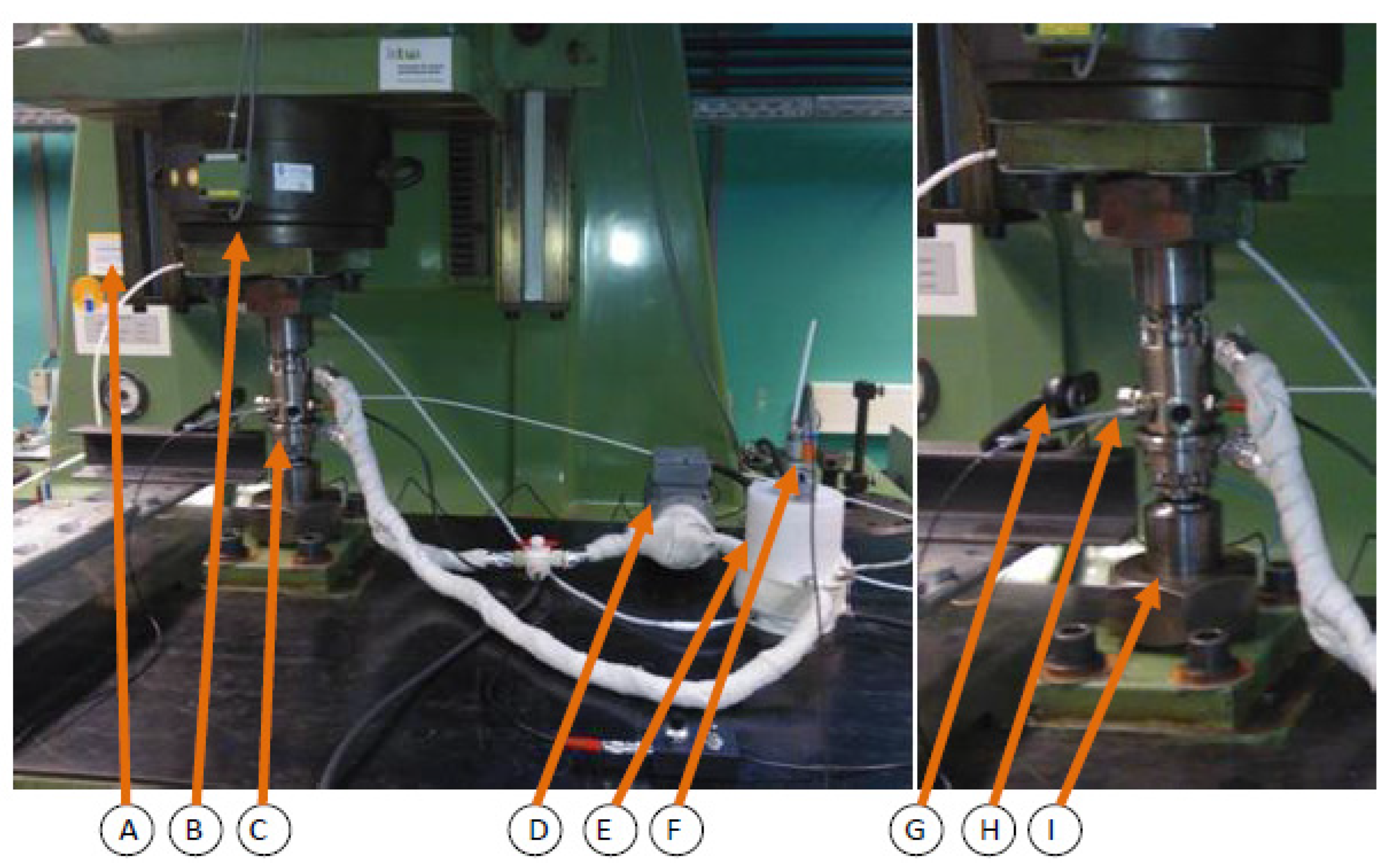
Corrosion fatigue test were conducted using hourglass specimens (critical cross-section is 12.5 mm in diameter) according to the standard DIN EN ISO 11782 1 and to the recommendations of the FKM Research Issue [54,55]. The resonant testing machine (sinusoidal dynamic test loads, R = −1; resonant frequency ~30 Hz) and corrosion fatigue testing have been explained has been in detail by Wolf and Pfennig [13,49]. The set up (Figure 1) was used to test 9 specimens between 280 MPa and 390 MPa.
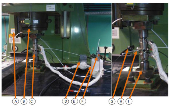
Figure 1.
Schematic set-up of operating corrosion chamber for in-situ corrosion fatigue testing (vertical resonant testing machine (A), clamping socket and plate (B), corrosion chamber (C), gear pump (D), aquifer reservoir with heating (E), pH-measuring and mixing unit (F), camera (G), thermocouple (H) and union nut (I)).
X-ray diffraction analysis was performed using a URD-6 (Seifert-FPM) equipped with CoKα-radiation, featuring automatic slit adjustment, a step size of 0.03, and a 5-s count. Phase analysis was carried out using AUTOQUAN® by Seifert FPM. For gravimetric measurement, samples were descaled by exposure to 37% HCl for 24 h, and the mass gain was analyzed according to DIN 50 905 part 1–4. Surface corrosion characterization utilized SEM/EDX with a Leo Gemini 1530 VP at an acceleration voltage of 15 kV. Pitting corrosion analysis involved 3D imaging with the Microprof TTV double optical system by FRT.
Sections of non-descaled samples were embedded in cold resin (Epoxicure, Buehler), cut, and polished with SiC-Paper ranging from 180 µm to 1200 µm under water. The final polishing stages included diamond paste with grit sizes of 6 µm, 3 µm, and 1 µm. Measurement of layer thicknesses, residual pipe wall thicknesses, and microstructure analysis were conducted through light and electron microscopy, utilizing the semi-automatic analyzing program Analysis Docu ax-4 by Aquinto.
3. Results and Discussion
To assess the potential damage to injection pipe steels and their protective coatings, experimental conditions were selected to replicate a harsh carbon capture and storage (CCS) environment, specifically focusing on the specimen fully immersed into the brine. This represents injection pauses under decreased pressure in the injection pipe where the water level may rise, affecting the conditions [13,21].
3.1. Influence of Alumina Coating on Static Corrosion Behavior of 1.4021
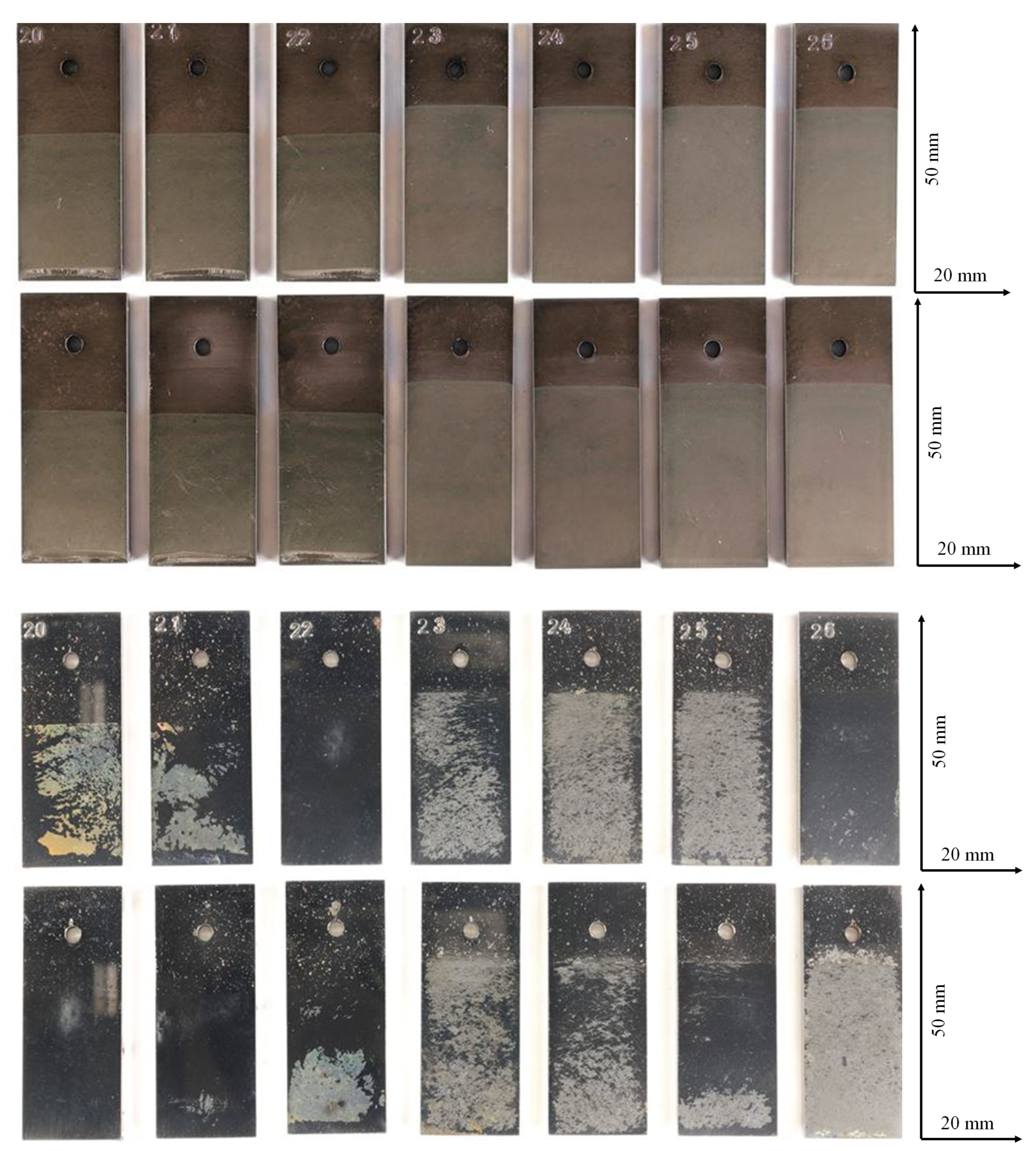
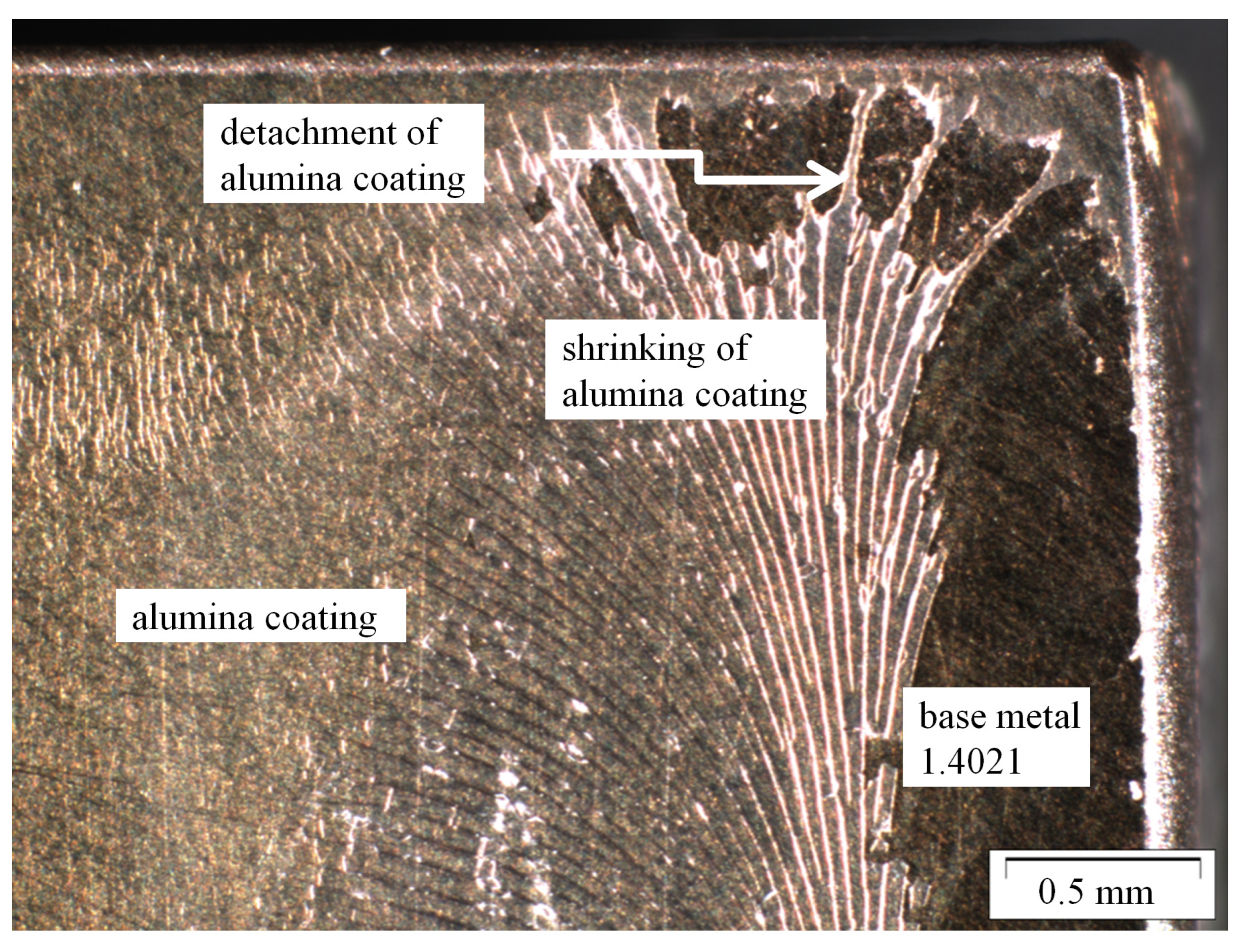
Figure 2 shows the sol gel coated (water based as well as ethanol based, binder: poly-vinylbutyral) coupons of X20Cr13 before and after exposure to CO2 saturated saline aquifer water at 60 °C and ambient pressure. The macroscopic degradation of the coating is demonstrated by lateral detachment of the coating and dissolution of the alumina sol (Figure 3). Regions of the coupon surfaces with degraded coating are highly susceptible towards CO2 corrosion and show typical corrosion products and patterns of uncoated samples as demonstrated earlier [13,21,56]. Surface corrosion layers and pits reveal both, FeCO3 and FeOOH as the main precipitation phases with no dependence on the coating. The lack of coating elements within the corrosion products indicate that the coating is detached before surface reaction take place at the newly exposed metal surface. Pit formation is driven by the formation of carbonic acid and existence of HCO3 as well as a transient ferrous hydroxide phase Fe(OH)2 reacting to corrosion products -mainly siderite- on the pits as detected on the surface elsewhere.

Figure 2.
Sample surfaces of water and ethanol based alumina coated martensitic stainless steel X20Cr13 after 1000 h of exposure to CO2 saturated saline aquifer water at 60 °C and ambient pressure. Top: coated, upper row: front side, lower row: back side. Bottom: corroded after exposure: upper row: front side, lower row: back side.

Figure 3.
Shrinking and detachment of water and ethanol based alumina coating on martensitic stainless steel X20Cr13 after 1000 h of exposure to CO2 saturated saline aquifer water at 60 °C and ambient pressure.
The corrosion kinetics of 1.4021 have been extensively studied [13,21] indicating that exposure at ambient pressure serves as a worst-case scenario simulation. The corrosion rates of coated coupons align with earlier findings for X20Cr13 at ambient pressure remained approximately 0.1 mm/year after 1000 h of exposure. Locally, regions fully coated showed very good corrosion resistance and low corrosion rates in the liquid phase (where coupons are fully immersed in the aquifer) are low, indicating that the CO2 partial pressure is not sufficient to initiate the corrosive reactions described by Wei et al. and Pfennig et al. [10,13]. Figure 3 and Figure 4 clearly show that ethanol based alumina sol does not coat the entire surface after exposure. Regions with locally destroyed coating reveal corrosion products according to the reactions and products stated earlier.
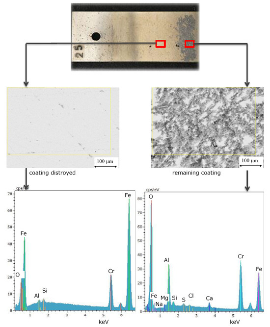
Figure 4.
Element distribution and surface images of different local regions on coupons of ethanol based alumina coated martensitic stainless steel X20Cr13, 1.4021 after exposure to and CO2 saturated saline aquifer water at 60 °C and ambient pressure.
There are three possible reasons for early failure of the coating (note that all samples were wetted perfectly prior to exposure to CCS environment):
- Due to the surface tension the coating is thinner towards the edges of the coupons than in the center. Therefore, stress causes micro cracking at the edges with the capillary forces driving the saline aquifer brine underneath the coating wetting the base metal surface.
- The high porosity may also be cause for the instability of the coating. The brine may have contact to the base metal surface through pores that connect surface and environment. Early corrosion reactions cause the coating to detach then in lateral direction.
- The reliability of the coating may also be reason for failure, because the method of coating directly influences the continuity and thickness of the coating. Dip coating leads to an increasing thickness of the coating towards the bottom of the samples because gravity forces the sol to flow before its gel status. Due to the “flowing” of the sol a bulge precipitates that has higher micro stress than the remaining coating. Therefor micro cracking of the coating is initialized within this bulge. In general, the reliability of the coating is directly dependent on the homogeneity of the coating and its consistent thickness avoiding stress gradients along the surface.
As Schulze et al. [34] state chromium and manganese diffusion into alumina improves the adhesion and protection of the coating. Especially, the role of chromium diffusion is important for the adhesion of the coating. In case of low alloyed steels containing less than 9 wt.% chromium, the alumina layer spalled off after the heat treatment for 0.5 h at service temperature of the respective steel [34]. X20Cr13 with 13% steel might have enough chromium for sufficient diffusion into the coating, but the heat treatment temperatures during exposure to CCS environment were too low for diffusion processes to be effective.
3.2. Influence of Alumina Coating on the Corrosion Fatigue Behavior of 1.4542
Earlier the authors presented the influence of corrosive media on the mechanical behavior of stainless steel AISI 630 (X5CrNiCuNb16-4, 1.4542) during carbon capture and storage as well as in geothermal energy production [13,21]. Earlier results do not change with alumina coatings indicating that the coating has no influence on the corrosion fatigue behavior. This includes S-N curve with low coefficient of correlation (r2 = 0.33) and a large scattering range (TN = 1:34.4), corrosion fatigue strength 60% below the endurance limit measured in air (620 MPa), reaching a maximum of 10 × 107 cycles at a stress amplitude of 150 MPa (Wöhler-exponent of k = 3.59), unusual corrosion pattern and failure related to statistical crack initiation due to either pitting or the formation of micro cracks depending on the stress amplitude [13].
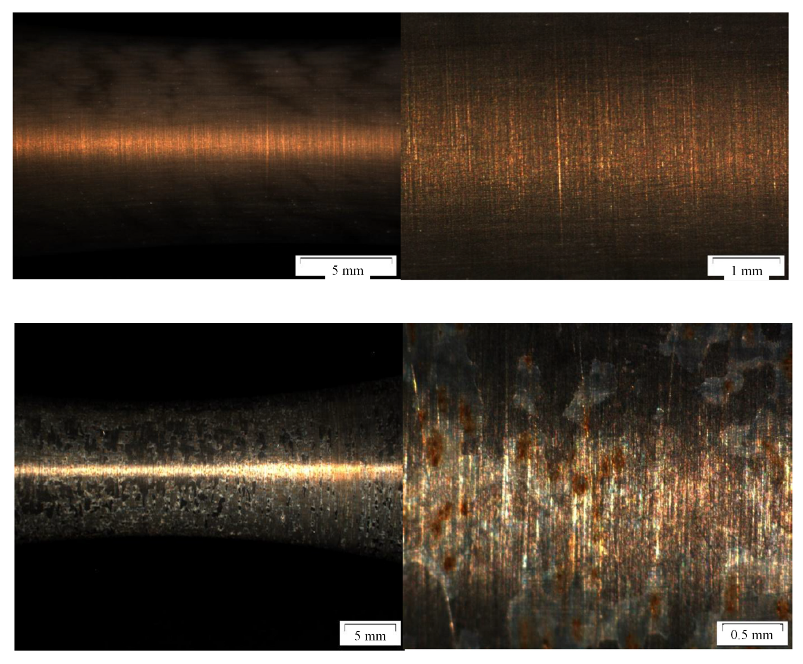
The influence of ethanol based alumina coatings of the fatigue behavior is demonstrated in Figure 5. The coating is distributed homogeneously over the test area of the specimen. Four specimen were tested, one failed due to machine failure but three reached 107 cycles at stress amplitude of 200 MPa. However, these endurance limits were only reached because of the low stress amplitude and are not related to the protection of the coating. The alumina coating was almost completely detached leaving the bare surface in contact with the corrosive environment resulting in severe pitting (Figure 5, bottom). An important finding is that this type of coating (first developed for high temperature alloys (use temperature > 550 °C) and nickel-base superalloys) does not perform in saline-water based aquifer environments with process gasses such as CO2. Also the considerable low drying and heating temperatures do not guarantee the adhesion of the coating.

Figure 5.
Fatigue specimen and surface image after coating with ethanol based alumina sol prior (top) and after (bottom) to exposure to CCS environment.
When a consistent protective coating is present on the metal surface, fatigue cracks are observed to initiate at alumina particles embedded in the substrate steel matrix during blasting, rather than at corrosion pits formed during testing, as highlighted by Oliveira et al. [48]. The researchers argue that the corrosion fatigue strength of a coated substrate is governed by the same mechanism that influences the fatigue behavior of the material in the air.
In the case of the detached ethanol-based alumina sol-gel coating on X5CrNiCuNb16-4, pits precipitate early, causing crack initiation comparable to the non-coated specimen within a corrosive environment (CO2-saturated saline water), according to Oliveira et al. [48]. Voorwald et al. [46] suggest that shot peening prior to coating provides an excellent alternative to increase the fatigue strength of AISI 4340 steel. In AISI 630, X5CrNiCuNb16-4, the residual stresses in the coating and substrate may change from tensile near the coating surface to compressive inside the coating center. These compressive stresses may then enable the coating to remain attached to the metal surface during fatigue testing.
4. Conclusions
Coupons and fatigue specimens made of X20Cr13 and X5CrNiCuNb16-4 were coated with water-based and ethanol-based alumina sol and exposed to CO2-saturated saline aquifer water for up to 1000 h, simulating conditions in the Northern German Basin, at ambient pressure and 60 °C in laboratory experiments. Corrosion fatigue experiments were conducted on coated X5CrNiCuNb16 specimens at 200 MPa stress amplitude, under ambient pressure, applying the same CCS conditions as for coupon tests.
Macroscopic surface images and the absence of coating elements within corrosion products indicate that the coating detaches before surface reactions occur. Surface corrosion layers and pits reveal carbonate corrosion products (FeCO3 and FeOOH) as the main precipitation phases, independent of the coating. Coating failure was observed in both static and dynamic tests accounting for water-based as well as ethanol-based coatings, rendering the alumina coating non-functional.
Early failure of the coating is possibly attributed to micro cracking due to surface tension gradient driving the saline aquifer brine underneath the coating which then wets the base metal surface. High porosity may also cause the instability of the coating resulting in early detachment. The reliability of the coating is directly dependent on the homogeneity of the coating and its consistent thickness avoiding bulges and stress gradients along the surface.
Although alumina-sol based spin coatings have been proven to show very good corrosion resistance in dry process gas atmosphere at high temperature this type of coating does not apply for CCS or general geothermal environment with high temperature and high water solubility being the most critical factors in CO2 gas mixtures.
Author Contributions
Conceptualization, A.P., W.M. and M.W.; methodology, A.P., W.M. and M.W.; software, M.W.; validation, A.P.; formal analysis, W.M. and M.W.; investigation, A.P., W.M. and M.W.; resources, A.P., W.M. and M.W.; data curation, A.P.; writing—original draft preparation, A.P.; writing—review and editing, A.P.; visualization, A.P.; supervision, A.P.; project administration, A.P.; funding acquisition, A.P. All authors have read and agreed to the published version of the manuscript.
Funding
This research received no external funding.
Data Availability Statement
Data are contained within the article.
Conflicts of Interest
The authors declare no conflict of interest.
References
- Thomas, D.C. Carbon Dioxide Capture for Storage in Deep Geologic Formations—Results from CO2 Capture Project, Volume 1: Capture and Separation of Carbon Dioxide from Combustion Sources. In CO2 Capture Project; Elsevier Ltd.: London, UK, 2005; ISBN 0080445748. [Google Scholar]
- Ruhl, A.S.; Goebel, A.; Kranzmann, A. Corrosion Behavior of Various Steels for Compression, Transport and Injection for Carbon Capture and Storage. Energy Procedia 2012, 23, 216–225. [Google Scholar] [CrossRef]
- Gale, J.; Davison, J. Transmission of CO2—Safety and economic considerations. Energy 2004, 29, 1319–1328. [Google Scholar] [CrossRef]
- Eldevik, F.; Graver, B.; Torbergsen, L.E.; Saugerud, O.T. Development of a Guideline for Safe, Reliable and Cost Efficient Transmission of CO2 in Pipelines. Energy Procedia 2009, 1, 1579–1585. [Google Scholar] [CrossRef]
- Russick, E.M.; Poulter, G.A.; Adkins, C.L.; Sorensen, N. Corrosive effects of supercritical carbon dioxide and cosolvents on metals. J. Supercrit. Fluids 1996, 9, 43–50. [Google Scholar] [CrossRef]
- Neši, S. Key issues related to modelling of internal corrosion of oil and gas pipelines—A review. Corros. Sci. 2007, 49, 4308–4338. [Google Scholar] [CrossRef]
- Förster, A.; Norden, B.; Zinck-Jørgensen, K.; Frykman, P.; Kulenkampff, J.; Spangenberg, E.; Erzinger, J.; Zimmer, M.; Kopp, J.; Borm, G.; et al. Baseline characterization of the CO2SINK geological storage site at Ketzin, Germany. Environ. Geosci. 2006, 13, 145–161. [Google Scholar] [CrossRef]
- Förster, A.; Schöner, R.; Förster, H.-J.; Norden, B.; Blaschke, A.-W.; Luckert, J.; Beutler, G.; Gaupp, R.; Rhede, D. Reservoir characterization of a CO2 storage aquifer: The Upper Triassic Stuttgart Formation in the Northeast German Basin. Mar. Pet. Geol. 2010, 27, 2156–2172. [Google Scholar] [CrossRef]
- Kissinger, A.; Noack, V.; Knopf, S.; Scheer, D.; Konrad, W.; Class, H. Characterization of reservoir conditions for CO2 storage using a dimensionless Gravitational Number applied to the North German Basin. Sustain. Energy Technol. Assess. 2014, 7, 209–220. [Google Scholar] [CrossRef]
- Wei, L.; Pang, X.; Liu, C.; Gao, K. Formation mechanism and protective property of corrosion product scale on X70 steel under supercritical CO2 environment. Corros. Sci. 2015, 100, 404–420. [Google Scholar] [CrossRef]
- Carvalho, D.; Joia, C.; Mattos, O. Corrosion rate of iron and iron–chromium alloys in CO2 medium. Corros. Sci. 2005, 47, 2974–2986. [Google Scholar] [CrossRef]
- Cui, Z.D.; Wu, S.L.; Zhu, S.L.; Yang, X.J. Study on corrosion properties of pipelines in simulated produced water saturated with supercritical CO2. Appl. Surf. Sci. 2006, 252, 2368–2374. [Google Scholar] [CrossRef]
- Pfennig, A.; Wolf, M.; Kranzmann, A. Corrosion and Corrosion Fatigue of Steels in Downhole CCS Environment—A Summary. Processes 2021, 9, 594. [Google Scholar] [CrossRef]
- Eslami, M.; Wang, X.; Choi, Y.-S. Electrochemical Study of Corrosion Resistant Alloys in Supercritical CO2 Environment. SSRN. 2023. Available online: https://ssrn.com/abstract=4571105 (accessed on 18 December 2023).
- Bowman, S.; Agrawal, V.; Sharma, S. Evaluating the Impact of Redox Potential on the Corrosion of Q125, 316L, and C276 Steel in Low-Temperature Geothermal Systems. Corros. Mater. Degrad. 2023, 4, 573–593. [Google Scholar] [CrossRef]
- Banaś, J.; Lelek-Borkowska, U.; Mazurkiewicz, B.; Solarski, W. Effect of CO2 and H2S on the composition and stability of passive film on iron alloys in geothermal water. Electrochim. Acta 2007, 52, 5704–5714. [Google Scholar] [CrossRef]
- Choi, Y.-S.; Colahan, M.; Nešić, S. Effect of Flow on the Corrosion Behavior of Pipeline Steel in Supercritical CO2 Environments with Impurities. Corrosion 2023, 79, 497–508. [Google Scholar] [CrossRef] [PubMed]
- Liu, J.; Yao, D.; Chen, K.; Wang, C.; Sun, C.; Pan, H.; Meng, F.; Chen, B.; Wang, L. Effect of H2O Content on the Corrosion Behavior of X52 Steel in Supercritical CO2 Streams Containing O2, H2S, SO2 and NO2 Impurities. Energies 2023, 16, 6119. [Google Scholar] [CrossRef]
- Choi, Y.-Y.; Nešic, S. Determining the corrosive potential of CO2 transport pipline in high pCO2-water environments. J. Green House Gas Control. 2011, 5, 788–797. [Google Scholar] [CrossRef]
- Han, J.; Zhang, J.; Carey, J.W. Effect of bicarbonate on corrosion of carbon steel in CO2 saturated brines. Int. J. Greenh. Gas Control 2011, 5, 1680–1683. [Google Scholar] [CrossRef]
- Pfennig, A.; Kranzmann, A. Understanding the Anomalous Corrosion Behaviour of 17% Chromium Martensitic Stainless Steel in Laboratory CCS-Environment—A Descriptive Approach. Clean Technol. 2022, 4, 239–257. [Google Scholar] [CrossRef]
- Mu, L.J.; Zhao, W.Z. Investigation on carbon dioxide corrosion behavior of HP13Cr110 stainless steel in simulated stratum water. Corros. Sci. 2010, 52, 82–89. [Google Scholar] [CrossRef]
- Islam, A.W.; Sun, A.Y. Corrosion model of CO2 injection based on non-isothermal wellbore hydraulics. Int. J. Greenh. Gas Control 2016, 54, 219–227. [Google Scholar] [CrossRef]
- Wang, J.; Zou, H.; Li, C.; Zuo, R.; Qiu, S.; Shen, B. Relationship of microstructure transformation and hardening behavior of type 17-4 PH stainless steel. J. Univ. Sci. Technol. Beijing Miner. Met. Mater. 2006, 13, 235–239. [Google Scholar] [CrossRef]
- Zhang, W.; Fang, K.; Hua, Y.; Wang, S.; Wang, X. Effect of machining-induced surface residual stress on initiation of stress corrosion cracking in 316 austenitic stainless steel. Corros. Sci. 2016, 108, 173–184. [Google Scholar] [CrossRef]
- Evgeny, B.; Hughes, T.; Eskin, D. Effect of surface roughness on corrosion behaviour of low carbon steel in inhibited 4 M hydrochloric acid under laminar and turbulent flow conditions. Corros. Sci. 2016, 103, 196–205. [Google Scholar] [CrossRef]
- Xu, M.; Zhang, Q.; Yang, X.X.; Wang, Y.; Liu, J.; Li, Z. Impact of surface roughness and humidity on X70 steel corrosion in su-percritical CO2 mixture with SO2, H2O, and O2. J. Supercrit. Fluids 2016, 107, 286–297. [Google Scholar] [CrossRef]
- Lee, S.M.; Lee, W.G.; Kim, Y.H.; Jang, H. Surface roughness and the corrosion resistance of 21Cr ferritic stainless steel. Corros. Sci. 2012, 63, 404–409. [Google Scholar] [CrossRef]
- Ahmed, A.A.; Mhaede, M.; Basha, M.; Wollmann, M.; Wagner, L. The effect of shot peening parameters and hydroxyapatite coating on surface properties and corrosion behavior of medical grade AISI 316L stainless steel. Surf. Coat. Technol. 2015, 280, 347–358. [Google Scholar] [CrossRef]
- Kleemann, U.; Zenner, H. Structural component surface and fatigue strength—Investigations on the effect of the surface layer on the fatigue strength of structural steel components. Mat. Wiss. U. Werkst. 2006, 37, 349–373. [Google Scholar] [CrossRef]
- Sanjurjo, P.; Rodríguez, C.; Pariente, I.; Belzunce, F.; Canteli, A. The influence of shot peening on the fatigue behaviour of duplex stainless steels. Procedia Eng. 2010, 2, 1539–1546. [Google Scholar] [CrossRef]
- Abdulstaar, M.; Mhaede, M.; Wollmann, M.; Wagner, L. Investigating the effects of bulk and surface severe plastic deformation on the fatigue, corrosion behaviour and corrosion fatigue of AA5083. Surf. Coat. Technol. 2014, 254, 244–251. [Google Scholar] [CrossRef]
- Wu, X.; Guan, H.; Han, E.H.; Ke, W.; Katada, Y. Influence of surface finish on fatigue cracking behavior of reactor pressure vessel steel in high temperature water. Mater. Corros. 2006, 57, 868–871. [Google Scholar] [CrossRef]
- Schulz, W.; Nofz, M.; Feigl, M.; Dörfel, I.; Saliwan Neumann, R.; Kranzmann, A. Corrosion of uncoated and alumina coated steel X20CrMoV12-1 in H2O-CO2-O2 and air at 600 °C. Corros. Sci. 2013, 68, 44–50. [Google Scholar] [CrossRef]
- Schulz, W.; Feigl, M.; Dörfel, I.; Nofz, M.; Kranzmann, A. Influence of a sol–gel alumina coating on oxidation of X20CrMoV12-1 in air up to 650 °C. Thin Solid Film. 2013, 539, 29–34. [Google Scholar] [CrossRef]
- Agüero, A.; Muelas, R.; Gutiérrez, M.; Van Vulpen, R.; Osgerby, S.; Banks, J.P. Cyclic oxidation and mechanical behaviour of slurry aluminide coatings for steam mturbine components. Surf. Coat. Technol. 2007, 201, 6253–6260. [Google Scholar] [CrossRef]
- Hübert, T.; Schwarz, J.; Oertel, B. Sol-gel alumina coatings on stainless steel for wear protection. J. Sol-Gel Sci. Technol. 2006, 38, 179–184. [Google Scholar] [CrossRef]
- Darut, G.; Ben-Ettouil, F.; Denoirjean, A.; Montavon, G.; Ageorges, H.; Fauchais, P. Dry Sliding Behavior of Sub-Micrometer-Sized Suspension Plasma Sprayed Ceramic Oxide Coatings. J. Therm. Spray Technol. 2010, 19, 275–285. [Google Scholar] [CrossRef]
- Choy, K. Chemical vapour deposition of coatings. Prog. Mater. Sci. 2003, 48, 57–170. [Google Scholar] [CrossRef]
- Fritsch, M.; Klemm, H.; Herrmann, M.; Schenk, B. Corrosion of selected ceramic materials in hot gas environment. J. Eur. Ceram. Soc. 2006, 26, 3557–3565. [Google Scholar] [CrossRef]
- Yoldas, B.E. Alumina Sol Preparation from Alkoxides. Am. Ceram. Soc. Bull. 1975, 54, 289–290. [Google Scholar]
- Vasconcelos, D.; Oréfice, R.; Vasconcelos, W. Processing, adhesion and electrical properties of silicon steel having non-oriented grains coated with silica and alumina sol–gel. Mater. Sci. Eng. A 2007, 447, 77–82. [Google Scholar] [CrossRef]
- Dressler, M. Sol-Gel Preparation and Characterization of Corundum Based Ceramic Oxidation Protection Coatings. Ph.D. Thesis, TU Bergakademie Freiberg, Saxony, Germany, 2006. [Google Scholar]
- Dressler, M.; Nofz, M.; Dörfel, I.; Saliwan-Neumann, R. Influence of sol–gel derived alumina coatings on oxide scale growth of nickel-base superalloy Inconel-718. Surf. Coat. Technol. 2008, 202, 6095–6102. [Google Scholar] [CrossRef]
- Tokaji, K.; Ogawa Hwang, J.U.; Kobayashi, Y.; Harada, Y. Corrosion Fatigue Behavior of a Steel with Sprayed Coatings. J. Therm. Spray Technol. 1996, 3, 269–276. [Google Scholar] [CrossRef]
- Voorwald, H.J.C.; Souza, R.C.; Pigatin, W.L.; Cioffi, M.O.H. Evaluation of WC-17Co and WC-10Co-4Cr thermal spray coatings by, HVOF on the fatigue and corrosion strength of AISI 4340 steel. Surf. Coat. Technol. 2005, 190, 155–164. [Google Scholar] [CrossRef]
- Schmitt-Thomas, K.G.; Meisel, H.; Seoler, W. Einfluß von Beschichtungen auf das Schwingungsrißkorrosionsverhalten des Chromstahls X20Crl3. Werkst. Und Korros. 1986, 37, 36–44. [Google Scholar] [CrossRef]
- Oliveira, F.; Hern’andez, L.; Berr´os, J.A.; Villalobos, C.; Pertuz, A.; Puchi Cabrera, E.S. Corrosion fatigue properties of a 4340 steel coated with Colmonoy 88 alloy, applied by HVOF thermal spray. Surf. Coat. Technol. 2001, 140, 128–135. [Google Scholar] [CrossRef]
- Wolf, M.; Afanasiev, R.; Böllinghaus, T.; Pfennig, A. Investigation of Corrosion Fatigue of Duplex Steel X2CrNiMoN22-5 3 Exposed to a Geothermal Environment under Different Electrochemical Conditions and Load Types. Energy Procedia 2014, 63, 5773–5786. [Google Scholar] [CrossRef]
- Gümpel, P.; Boskovic, L.; Straub, J.; Bogatzky, T.; Henkel, B.; Sorg, M.; Hörtnagl, A.; Bauer, A. Rostfreie Stähle: Grundwissen, Konstruktions- und Verarbeitungshinweise, 4th ed.; Expert Verlag: Renningen, Germany, 2008; ISBN 978-3-8169-2689-4. [Google Scholar]
- Nofz, M.; Pauli, J.; Dressler, M.; Jügeg, C.; Altenburg, W. 27Al NMR Study of Al-Speciation in Aqueous Alumina-Sols. J. Sol-Gel Sci. Technol. 2006, 38, 25–35. [Google Scholar] [CrossRef]
- Dressler, M.; Nofz, M.; Gemeinert, M. Rheology, UV-vis transparency and particle size of modified Yoldas sols. J. Sol-Gel Sci. Technol. 2006, 38, 261–269. [Google Scholar] [CrossRef]
- Dressler, M.; Nofz, M.; Malz, F.; Pauli, J.; Jäger, C.; Reinsch, S.; Scholz, G. Aluminum speciation and thermal evolution of aluminas resulting from modified Yoldas sols. J. Solid State Chem. 2007, 180, 2409–2419. [Google Scholar] [CrossRef]
- Buschermöhle, H. Vereinheitlichung von Proben für Schwingungsversuche. In FKM Forschungsheft 217; VDMA Services GmbH: Frankfurt, Germany, 1996. [Google Scholar]
- DIN 50905-1:2009-09; GmbH: Korrosion der Metalle—Korrosionsuntersuchungen—Teil 1: Grundsätze. Beuth Verlag: Berlin, Germany, 2009.
- Bäßler, R.; Sobetzki, J.; Klapper, H.S. Corrosion Resistance of High-Alloyed Materials in Artificial Geothermal Fluids. In Proceedings of the Vol. NACE Inter Nr. Corrosion 2013, Orlando, FL, USA, 17–21 March 2013; p. 2327. [Google Scholar]

Disclaimer/Publisher’s Note: The statements, opinions and data contained in all publications are solely those of the individual author(s) and contributor(s) and not of MDPI and/or the editor(s). MDPI and/or the editor(s) disclaim responsibility for any injury to people or property resulting from any ideas, methods, instructions or products referred to in the content. |
© 2024 by the authors. Licensee MDPI, Basel, Switzerland. This article is an open access article distributed under the terms and conditions of the Creative Commons Attribution (CC BY) license (https://creativecommons.org/licenses/by/4.0/).