1. Introduction
Helicopter blades are essential elements that can withstand high loads and, at the same time, need to be as light as possible. To meet these requirements, helicopter blades are manufactured using composite materials: carbon fibre, fibreglass, and Kevlar fibre [
1]. In order for the helicopter blade to be used safely and with maximum efficiency, several structural criteria must be taken into account [
2,
3]: high resistance to forces in the axial direction, which is the main stress, as well as the secondary stress coming from the bending forces acting through the lift force generated by the aerodynamic profile of the blade and its angle of attack; low mass, which is necessary for two reasons: the first is the additional fuel consumption that the helicopter has to sustain to generate the force required to rotate the blades and the second is that through the action of the centrifugal force the mass effect of each fraction is amplified by at least one or two orders of magnitude, which further stresses the blade structure in the axial direction; and the fatigue strength of the material is also a very important factor as it is part of a dynamic assembly, the blade is constantly subjected to a load-unload cycle, which leads over time to fatigue cracks [
4] and failure. The core of the helicopter blades [
3] can be made of foam or a honeycomb structure (metallic, composite, and Nomex).
Composite materials are replacing the conventional ones (metals and wood) in the structure of helicopter blades due to their ease of processing and productivity. The main advantages of carbon fibre and fibreglass composites are the following [
5,
6]: high strength-to-weight ratio, excellent fatigue resistance compared to metal alloys, high strength, high corrosion resistance, and anisotropy (different physico-mechanical properties in different directions). These properties are the main reasons for the use of composites in the manufacture of aircraft parts, which are improved performance resulting from the ability to optimise the shape, structure, and mechanical properties of the parts, and weight reduction, which improves the efficiency of the parts and the aircraft and allows a higher load or operating range for the aircraft [
7].
Due to the fierce competition between companies, there is a desire to introduce superior products to the market in terms of operational performance, which can be achieved using accelerated reliability testing for blades [
8] but also by determining reliability indicators for the spar structure of helicopter rotor blades [
9]. An important aspect of helicopter maintenance and flight safety activities is the determination of blade life using fatigue stands and tests [
3,
10]. Fatigue is the process of localised, progressive, and permanent structural changes in one or more areas of the blade under stress that produce variations in stress and strain and may culminate in cracking or complete failure after a sufficient number of oscillations [
11,
12]. The vital components (blades) of the helicopter structure are subject to particularly rigorous testing, as they cannot be doubled and their failure can lead to serious accidents [
13,
14]. Another method used since the early stages of aeronautical products is finite element analysis (FEA). Various studies [
15,
16,
17] determine the distribution of equivalent stresses and total displacements for helicopter blades made of composite materials by FEA. Another research direction dedicated to the study of helicopter blades is aerodynamic optimisation using neural networks based on CFD solutions [
18]. In order to design blades with the longest life and the best stress resistance, engineers very closely analyse the behaviour of blades in service; therefore, non-destructive methods [
19,
20] and failure mode analysis [
21,
22] are current activities in the life cycle of aircraft parts.
The use of 3D printing in industry is particularly popular with TDVs (tools, devices, and verifiers) due to the fact that they are used for specific tasks, especially in the production of prototypes and single units of immediate need [
23,
24]. Thus, by using additive manufacturing processes, lead times are shortened and so costs decrease. This is possible because traditionally immediate-need TDVs are manufactured using computer numerical control (CNC) machines, which increase production and maintenance costs for this section that represents manufacturing preparation for a part/sub-part [
25]. TDVs used in production that are currently suitable for additive manufacturing are represented by the following categories: templates for layout/marking [
26,
27], positioning/assembly devices [
28,
29], moulds for vacuum forming [
30,
31], moulds for injection moulding of plastics or vulcanisation of rubber [
32,
33,
34], presses for bending thin sheets [
35,
36,
37], and moulds for making composite parts [
38,
39,
40].
The moulds used for the production of composite parts have developed with the evolution of additive manufacturing processes and are mainly used in processes and technologies that operate at low temperatures and pressures. Given the high cost of a mould made by conventional processes, additive manufacturing processes are an alternative that reduce cost and production time due to the flexibility of parts that can be manufactured using 3D prototyping [
41].
An important direction of research is the production of composite blades using different methods of manufacturing using moulds. In a recent study [
42], a composite blade of the tail rotor of the IAR330 helicopter was designed and analysed using the finite element method. This blade was manufactured, at a scale of 1:3, from carbon-roving spar embedded with epoxy resin, a 3D-printed honeycomb core, and an outer skin made by hand lay-up of multiple carbon-fibre-reinforced laminae; the major advantage of manufacturing this kind of blade is the low cost.
Dippenaar et al. [
43] manufactured a wind turbine blade, made of carbon fibre, using the vacuum-assisted resin transfer moulding (VARTM) process and a 3D-printed mould. The main contributions of the study are the technical evaluation of the process and a cost model for 3DP moulds for VARTM that can be used to assess the feasibility of the process. It was also observed that the 3D print tooling is less accurate compared to tools made on CNC but that there is a cost and time advantage to making tooling with 3D printing processes. The life of the 3D-printed mould is limited to 15 to 30 parts, as significant wear occurs in the manufacturing process [
43].
Bell and Ingersoll Machine Tools companies partnered to additively manufacture a long vacuum trim tool used to produce rotor blades for helicopters, using a hybrid machine that combines 3D printing and 5-axis milling [
44]. A partnership of the US Department of Energy’s (DOE) Oak Ridge National Laboratory (ORNL), National Renewable Energy Laboratory (NREL), Sandia National Laboratories, and private company TPI Composites demonstrated the feasibility of manufacturing wind turbine blades using 3D-printed moulds, highlighting the reduced manufacturing time and cost of these tools [
45].
In this paper, the feasibility of the process of manufacturing a composite helicopter blade using a 3D-printed mould was demonstrated. To obtain the composite helicopter blade, all the necessary steps were carried out, starting from the design of the mould, 3D printing and assembly of the mould sections, and blade manufacturing; finally, a comparative study was carried out on the costs of manufacturing a 3D-printed mould and the costs of a CNC manufactured mould.
2. Mould Design
For the design of the mould needed to manufacture the IAR 330 helicopter anti-torque rotor blade from composite materials, several factors must be established regarding the operation of this part. When the design phase of the mould starts, it is important to know the role and the way the blade is used in operation, so that the most appropriate decisions can be made regarding the manufacturing method taking into account the practical use.
For the manufacture of the mould, two manufacturing processes have been analysed, so the process can be customised for the project in question (blade), which leads to a structural solution superior to the one chosen without a prior study of the existing documentation. The manufacturing of the moulds used is carried out by conventional milling processes, which can make it difficult to obtain the air foil in areas of high interest, with these areas being the air foil edges (leading and trailing).
One of the methods considered is conventional moulding in which the anti-torque blade is manufactured using two moulds (upper and lower) that make up the blade profile. To these, the following blade parts are added: the spar, made of roving fibres; the core made by machining; and the shell, which is assembled in the mould and cured under pressure in an autoclave. Although it is a faster process in terms of the moulds and tools used, this type of manufacturing requires external pressure and the presence of a vacuum in order to be carried out. The control of the composite materials used in the technological process is not 100% possible because once the mould is closed there is no definitive certainty that each start is in the position in which it was originally placed, which can result in ridges in the surface of the shell or bending of the whole assembly [
46].
In the second method, the main spar of the blade is made with a vacuum and the shell and supporting structure are added separately by bonding and lamination. With this method of manufacturing and moulding, the quality and dimensional control of the blade parts can be much better monitored and controlled, resulting in a higher overall quality of the finished product. A disadvantage of this manufacturing method is that it requires three distinct types of moulds: one for manufacturing the blade spar, one for manufacturing the shell, and one for manufacturing the composite assembly, assuming that the material used for the insert is machined or prefabricated by extrusion beforehand. This method is therefore also costly and time-consuming due to the large number of TDVs required to manufacture the part. The big advantage is to obtain a hollow inner cavity, which reduces the total mass of the blade. The structural stiffness of this structural solution is high due to the fact that the moment of inertia area of the spar section is increased by the arrangement of composite material fibres at the edge of the blade geometry [
47].
The helicopter blade (
Figure 1a) is made up of two types of geometric sets, the first geometric set (monoblock area—
Figure 1b) refers to the area where the blade is embedded in the rear rotor hub of the aircraft and is intended for the blade embedment and transmission of the lift force. The second geometric set (constant chord area—
Figure 1c) is the lifting structure, which plays a role in creating the desired aerodynamic effect.
Of particular importance from the point of view of manufacturing preparation is the achievement of the tolerances required by the product (blade). The following two general types of tolerances must be met:
The geometry of the structure that serves to embed the blade in the rear rotor hub is suitable for a monoblock solid lamination made of a composite material chosen by the product designer. Thus, this section should be made using a compression mould, with such moulds being able to obtain complex solid geometries. The second section of the blade is geometrically constant, so after the connecting section between the two bodies, the body with a constant aerodynamic aerofoil is created. This blade section can be produced using conventional moulds or compression moulds.
In conclusion, the compression moulding option is chosen for the manufacture of the blade, as this option offers good possibilities for fast manufacture and ease of the digital model design. The geometry of the anti-torque blade allows the manufacture of a mould with a single separating plane, thus resulting in a mould consisting of two moulds: an upper one and a lower one. The lower mould acts as a loading area for the laminating materials and the upper mould acts as a punch. The punch, once assembled, is used to create the geometry on the upper surface of the blade and during the compression of the laminate composite, it evacuates the air and excess resin that has been added during the lamination process. The compression carried out by the mould punch also presses the layers of the composite material so that the volume ratio between fibres and reinforcing resin is approximately 50% composite fibre and 50% reinforcing resin. This is particularly important in manufacturing the blade to ensure resin impregnation throughout the volume of the fibres that does not contribute structurally to the stiffness of the blade, without adding resin mass.
The design of the lower mould construction is to create a cavity deep enough to allow for the arrangement of the blade materials. Thus, the geometry of the lower surface of the blade is carried out in the body of the mould. Additional processes are added to the inner vertical walls of the mould to allow the extraction of the punch after curing and to facilitate the removal of the blade. Thus, in the case of the lower mould, the draft angle of the inner walls was 5°. The main aspect of the design of TDVs for this manufacturing process is to include a telescopic section, where the upper mould acts as a punch in a cylinder during its closing. This allows the uncompressed fibres to be filled in and during closing the excess resin will be squeezed out through the separation line; but, due to a tight fit, the fibre cannot be removed, leaving the correct fibre to resin ratio. This telescoping element or punch must be deep enough to allow the mould to start closing before disrupting the fibre. The exact size of this element varies depending on the shape and design of the mould but, generally, it should extend to at least 25% of the depth of the final part. In the case of a two-part mould, this requires a draft angle of 3–5 degrees to allow easy separation of the mould.
In order to allow easy and unambiguous identification in both the design and the tracking and implementation process, the two moulds will be named as follows:
The female (lower) mould or the mould into which the fibres have been loaded is named MAT-COMP V3-FEMALE (
Figure 2a);
The male mould (upper) or the mould which compresses the composite material after lamination is called MAT-COMP V3-MALE (
Figure 2b).
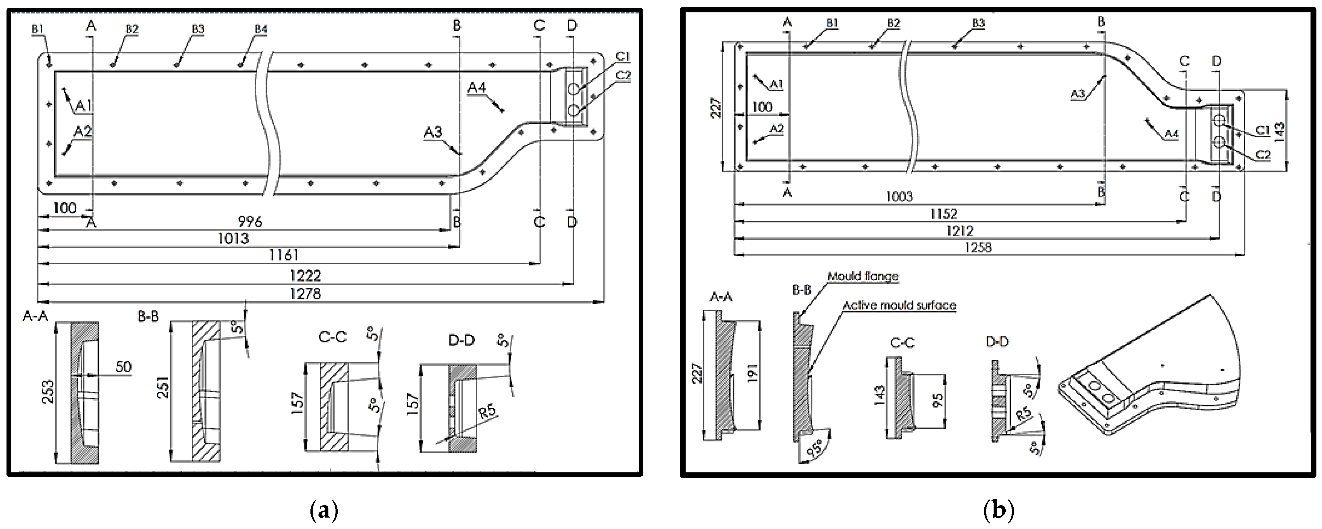
The lower mould (
Figure 2a) has three types of bores in its body, which are used to assemble and position the fixing and extraction elements after polymerisation. These types of bores are not essential in the manufacturing process but with their help, the yield of the mould is greatly increased due to the much more efficient guiding of the two moulds when closing them. The first set of bores is used to position the blade core in the mould and to fix it in position. At the same time, the clamping rods that go into the bores also act as extractors once the anti-torque blade has been laminated and the curing process is complete. These bores are shown in
Figure 2 and are numbered alphanumerically as A1, A2, A3, and A4. The positioning of these bores allows the application of the extraction forces to be distributed close to the vertical walls of the mother mould, to corners, or to geometric surfaces that are difficult to extract, for example, the tip of the blade area and the blade embedment area. The second set of bores, B1, B2, and B3, is used for the assembly parts (screw shank) that are arranged around the blade contour and their purpose is to provide the necessary compression force to the punch to remove the excess resin. Their diameter is 8.2 mm and the assembly is carried out with a clearance fit. This increased tolerance ensures that each screw can be assembled and take up the deviations from the 3D printing process of the mould. The C1 and C2 bores have a diameter of 20 mm and, by means of two polyamide rods, place the embedded metal bushings in the embedded tip of the composite blade. In other words, the positions of the C1 and C2 bores determine the centre of the axis of the bolts that assemble the blade to the rear rotor hub, so the tightest tolerance in the whole mould assembly can be found here, which is ±0.02 mm.
The upper mould (
Figure 2b) is manufactured from a punch, which has the active surface machined according to the geometry of the upper surface of the blade, in order to shape the laminated composite in the mould. The 5° draft angle is added to this surface, also present on the surface of the lower mould, and the upper part of the male mould ends with a clamping flange that will ensure pressure on the freshly laminated blade. A similar system of B bores is found in the flange of the upper mould and allows the passage of the screw shank, thus allowing the mould to close. The positioning A bores are present in the body of the upper mould but, unlike the lower mould, they serve only to position the rods guiding the anti-torque blade core. The extraction from the punch is not necessary in this case. The positioning of the polyamide rods securing the metal bushes embedded in the composite is performed similarly to the lower mould. It is important to mention the concentricity condition to be met by the C1 and C2 bores used in the two moulds. This condition of concentricity actually ensures the perpendicularity of the axes of the embedded metal bushes to the plane of symmetry of the composite blade, which is essential in future measurements and checks that the blade has undergone the appropriate steps before it is mounted on the helicopter. Another important aspect is that after lamination, the axes of the embedding bushings are considered as reference points and starting points for future operations as well as for their mounting on the aircraft.
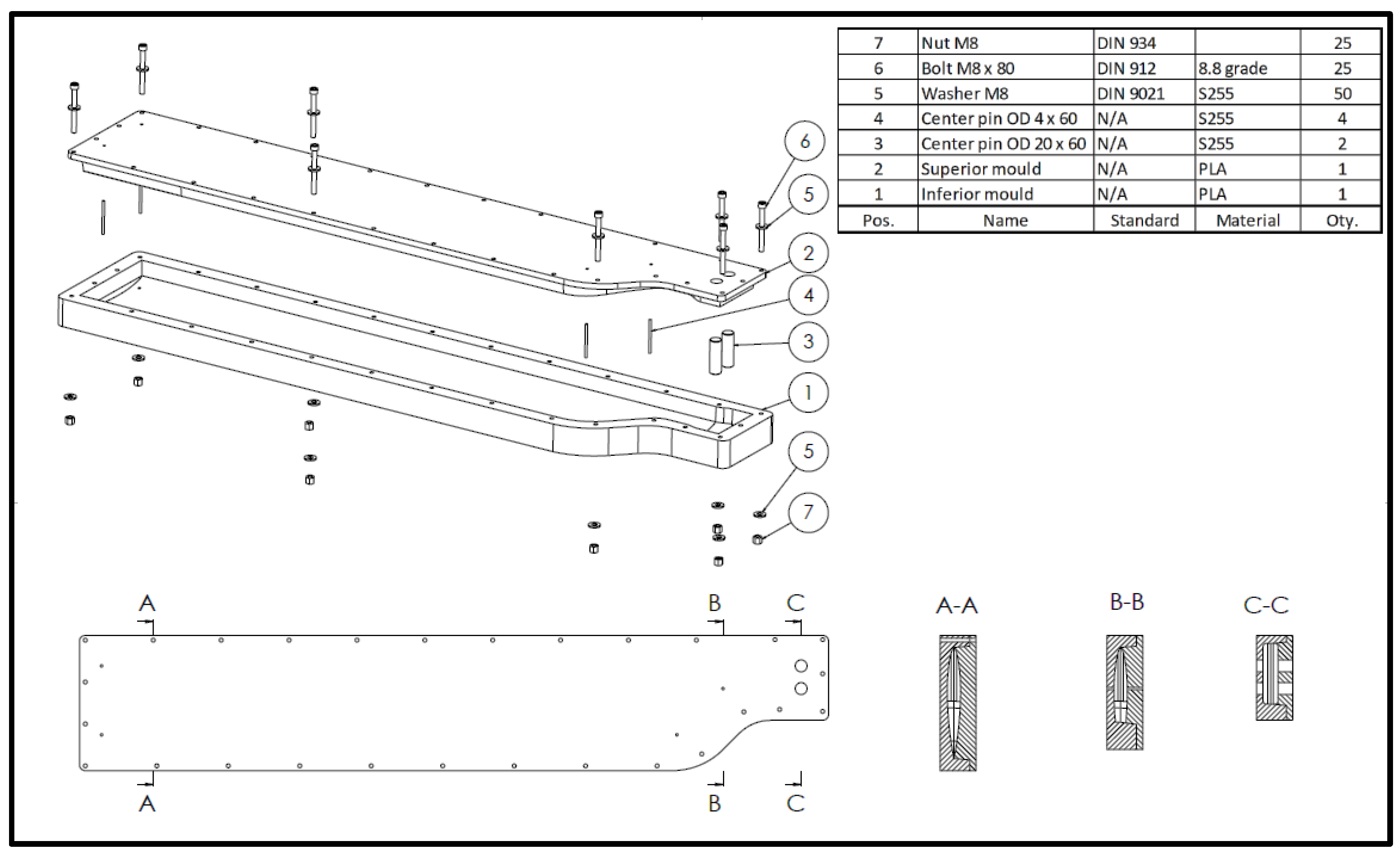
For a better understanding of the manufacturing process of the anti-torque blade, the assembly and operation of the mould are further described. The design of the mould would be incomplete without describing the plan of the operations that are carried out with it. In fact, it is at this stage that the set of TDVs required for a lamination operation begins to become clear. The lower mould placed with the active area upwards on the workbench is equipped with guide rods for the blade insert and guide rods for the steel bushes to be embedded in the blade. Notably, the assembly between the guide rods is made with slide clearance as follows: H7/g6, so that the required geometric tolerance can be ensured. The next step in the assembly is the fitting of the metal bushes into the mould, followed by the closing of the mould by placing the upper mould on top, moving it in the Z direction ensures the closing. Guiding of the upper mould at the time of closing is achieved by means of guide rods (position 4 in
Figure 3) and vertical walls in which the draft angle has been included. The mould is then assembled with M8 × 80 screws and clamping is carried out until the upper mould flange is in contact with the lower mould (
Figure 3).
For high-volume manufacturing, compression moulding tools for this process are usually made of aluminium or steel machined by milling. These obviously offer excellent strength and durability but are expensive to produce, making them less viable for small series and prototypes.
Design parameters taken in consideration for the mould of the anti-torque blade are as follows (
Table 1): volume to be filled by layup process, cavity design, and clamping force required in order to evacuate the excess resin, geometrical dimensions, tolerances, and part removal when the curing process is finished.
For the design of the 3D-printed mould, the following aspect was also taken into account: the minimum wall thickness should be at least 3 mm and cores with thick sections should be used to prevent thermal cracking due to curing and mould damage due to high exotherms [
43,
49,
50].
3. Three-Dimensional Printing of the Mould
In this study, the direct 3D-printed TDV moulding method was used with the Ultimaker S5 printer (Ultimaker, Utrecht, The Netherlands). Although this 3D-printed mould does not offer the strength and durability of conventional moulding tools, it has the advantage of being very cheap, fast in manufacturing, and very useful for small series and prototypes. Using this method with a 3D-printed mould allows the production of parts with very high mechanical performance without the need for additional specialised equipment or tools. Although other types of filaments can also be used, polylactic acid (PLA) has been found to offer high precision, low shrinkage, and ease of printing, making it an excellent choice for mould making [
51,
52,
53].
The affordable cost of PLA is still a determining factor in choosing it for mould making. Compared to filaments made from acrylonitrile butadiene styrene (ABS) or nylon, the filament made from PLA is about 20% cheaper than these. This makes it a suitable choice for moulds that require a large amount of material but for projects that do not have a large budget. The environmentally friendly and sustainable aspect of PLA is due to the fact that it is made from renewable raw materials such as corn or other plants, making it an environmentally friendly material. PLA production generates lower CO
2 emissions and uses less energy than petroleum-based materials such as ABS. PLA is also biodegradable, which means that it can be broken down naturally by microorganisms in the environment [
54]. This characteristic makes PLA a suitable choice for applications that require minimal environmental impact [
55].
In order to manage the 3D printing of a mould that exceeds the printing dimensions of the 3D printer in the X and Y directions, an alternative solution was needed to divide the mould into smaller sections that can be printed separately. However, a major drawback associated with this method is that once the initial mould geometry is split, the accuracy of the mould decreases along the direction in which it is split. To compensate for this problem and to ensure a correct and accurate assembly of the resulting mould from individual sections (
Figure 4a), a puzzle-type assembly (
Figure 4b) was chosen.
Due to the geometry of the cylindrical section and similar dimensions there is a risk of mixing up sections within the same mould. To combat this risk, each part is marked as shown in
Figure 4b. This also ensures the correct assembly of the moulds and the alignment of the fixing and assembly bores. By using this assembly method, each section of the mould can be accurately and securely positioned and clamped, ensuring the correct geometry and stability of the final mould. It is essential that the assembly process is well planned and that each part fits perfectly into the puzzle template, avoiding discrepancies or clearances that could affect the final mould. This approach offers a practical and efficient solution for 3D printing large-sized moulds using a 3D printer with limited capacity. Precise mould splitting and assembly allows large moulds to be manufactured affordably and efficiently without compromising the quality and accuracy of the final mould.
The choice of the sectioning areas is made by taking into account two important design parameters in terms of the structural integrity of the mould, as follows:
The first aspect considered is the size of the printing bed plate because after trials and tests it was concluded that by making a section for printing using the maximum printing bed plate size (330 mm × 240 mm), the marginal geometry was made with poor geometrical tolerances and questionable structural integrity. As a result, the size of the 3D printer bed plate was taken as a reference, 240 mm × 240 mm, for dividing the sections of the two moulds (upper and lower);
The second aspect is related to the integration of the bores present in the mould in the same printed section. The decision was taken not to split a bore between two 3D-printed sections. By doing so, each section of the moulds can work independently when assembled and they are responsible for the cross-sectional result of the anti-torque blade. The overall assembly of the mould was responsible for supporting the sections and arranging them rectilinearly.
The CAD model sections of the mould were saved in STL (stereolithography) format to be imported into the Ultimaker Cura 4.13.1 manufacturing preparation software system (Ultimaker, Utrecht, The Netherlands). The manufacturing parameters for the PLA filament of the 3D printing process for the mould sections are presented in
Table 2. The high thickness of the outer walls of the sections, as well as the infill density of 30% with an infill pattern grid, ensures superior mechanical behaviour, so the mould can withstand the stresses that develop when it is closed.
In
Figure 5a,b, the positioning of the mould sections on the building plate from the software system for preparation for manufacturing was described and finally, a section made by the 3D printing process can be observed.
The 3D printing time and filament consumption involved in the manufacturing of the anti-torque blade mould, as presented in
Table 3, show the size or the order of magnitude of the working time required, as well as the material consumption. Thus, the manufacture of the MAT-COMP V3-FEMALE sections took 254 printing hours and used 572.44 m of filament or approximately 4.5 kg of PLA filament. The sections of MAT-COMP V3-FEMALE were manufactured in 248 printing hours and used 615.86 m of filament or approximately 4.8 kg of PLA filament. Finally, the 3D printing of the upper and lower mould sections took 502 h, consuming 1188 m of PLA filament and 9.3 kg of PLA filament. To reduce the time of manufacturing the mould, an efficient option could be the use of the 3D print farm. This production line, formed by a group of 3D printers that manufacture simultaneously and as much as possible without stopping, aims to increase the production rate of printed parts.
4. Composite Blade Manufacturing
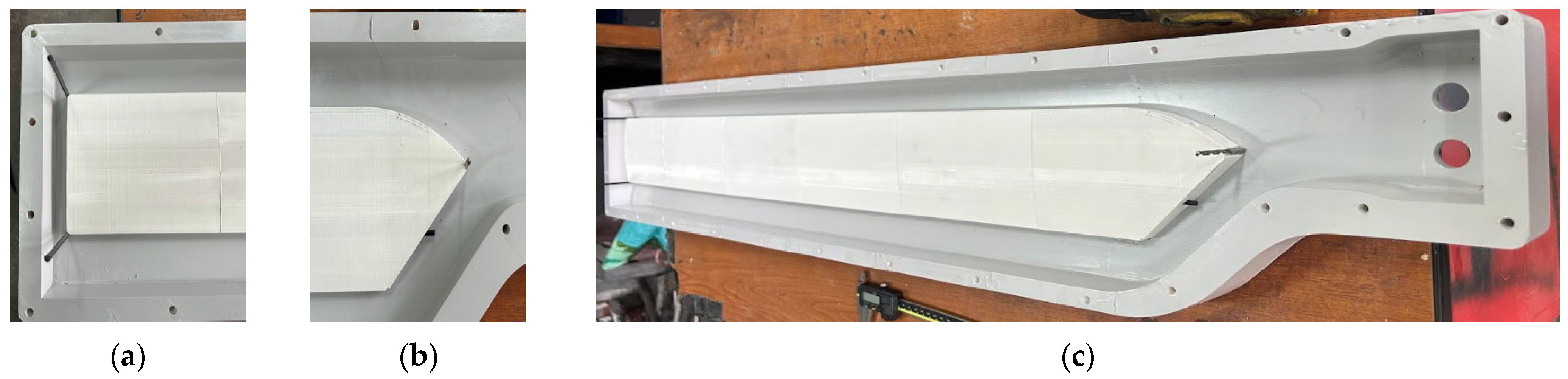
After the sections of the two moulds are 3D printed (
Figure 6a), they are assembled using a rubber hammer and a polyamide punch and placed on a flat plane. The sections are bonded together (
Figure 6b) using a polyurethane adhesive, which has the advantage that as it hardens, the volume of the adhesive increases, thus ensuring the tightness of the mould and filling any gaps that may occur. The assembly of the mould is followed by the adjustment of the active surfaces. These are sanded and, where necessary, filled with putty to fill in low areas and even out the surface. Next, the mould is coated with a layer of 2K primer (
Figure 6c), which serves as a separation layer between the composite (blade) and the 3D-printed mould.
The manufacture of the anti-torque blade begins with the preparation of the parts that are to be used and the preparation of the moulds. Thus, the first step is to manufacture the blade core by 3D printing (
Figure 6d). To do so, the following were of great importance: the walls should be as thin as possible and the infill density as low as possible. The blade core takes the place of a structure for which traditionally, various materials are used [
56,
57], namely PVC foam (polyvinyl chloride), moltoprene, Nomex honeycomb, and metallic honeycomb. The advantage of a 3D-printed core allows the construction of a hollow cavity which decreases the overall mass of the finished part. The core is manufactured on a Prusa MK2 3D printer (Prusa Research a.s., Prague, Czech Republic) from PLA filament, it has an outer wall of 0.3 mm and 4 inner stiffening ribs of the same thickness (
Figure 6d); additionally, it has two perforated bores allowing the insertion of carbon rods.
As shown in
Figure 6e, the anti-torque blade is built from the outside to the inside from a carbon fibre shell, which encloses a structural box girder made of two unidirectionally-arranged fibreglass spars, the direction of lamination being in the blade span. In the mid-section, the blade box girder is made up of a 3D-printed core through the middle of which two 4 mm diameter carbon rods pass. These rods are used to join the core structure, which is made up of six sections. The tips of the rods are inserted into the end section of the blade core and pass through the perforated bores of the core. These rod tips are embedded in the carbon section called the monoblock section of the blade. Additionally, after the lamination of the monoblock structure, two layers of Kevlar are laminated to the leading edge. The Kevlar layers are added for reinforcement of the structure in case of impact or to prevent premature wear of the blade.
In order to obtain a roughness of the active surfaces of the two moulds (upper and lower), two models of the upper surface (
Figure 7a) and lower surface (
Figure 7b) of the blade were manufactured by the thermoplastic extrusion process, this time being positive shapes of the mould section. The active surface of the mould is sanded with the help of these and abrasive paper of different grits. The grits of the abrasive paper used are in ascending order as follows: 120, 180, 240, 320, 480, 600, and 1000 (note that the sanding for grits of 480 and above was conducted in the wet condition).
As shown in
Figure 8a, after 3D printing and assembly of the core, it is inserted into the mould for a final trial run for the geometry to be used further and to make the necessary adjustments. In order to control the position of the core inside the mould as precisely as possible, four centring studs are used (
Figure 8b), which are arranged as follows: two at the distal end of the core and two at the proximal end of the core (
Figure 8c).
Once the core is made, the next step is to cut the layers of material that make up the anti-torque blade. The layers are cut according to the draping diagram. The draping diagram is usually specified in the design drawing of the part and specifies the type of layers (fibreglass, carbon fibre, Kevlar, etc.) found in the composition, the density of the layer per square metre (200 g, 300 g, 600 g, etc.) their size (cutting dimensions), the orientation or positioning of the layers on the part in relation to the main axis of the part, and the order in which they are laid down.
Next, five successive layers of wax are applied to the surface of the two moulds to create a separating film between the composite blade and the 3D-printed mould. These wax layers are intended to make it easier to remove the blade from the 3D-printed mould after the polymerisation process is complete. The layers are applied sequentially with a strip of fabric at 15 to 20 min intervals between applications to allow the layers to adhere to the moulds and to each other.
Layer cutting is performed by hand, using scissors specially designed for fabric-type products. This is how the layers are cut.
The fibres that are part of the blade are as follows:
Carbon fibre fabric 2 × 2 twill 3K with a weight of 200 g/m
2 [
58]: six layers are cut to form the blade shell and three layers are placed on the lower surface and three layers are placed on the upper surface;
Fibreglass fabric, with a weight of 200 g/m
2 [
59], is cut as follows:
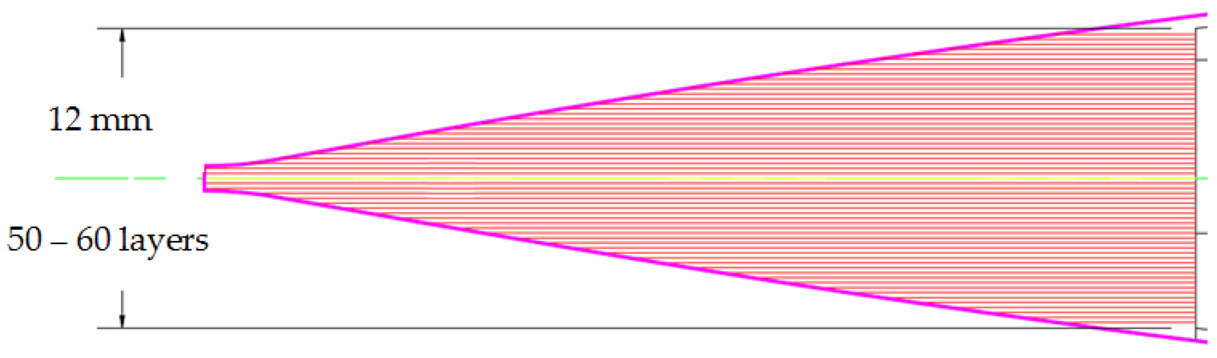
For the spar constituting the leading edge of the blade (
Figure 9), about 75 layers are cut, ranging in width from 5.5 mm to 31 mm. The variation in layer width is necessary to form the specific shape of the leading edge.
Approximately 50 layers of varying widths between 5.5 mm and 40 mm were required for the spar constituting the trailing edge (
Figure 10).
- 3.
Short fibres:
made of Kevlar: they are obtained by cutting a Kevlar fibre fabric with a weight of 300 g/m
2 [
60];
made of carbon: they are obtained by the same process as the fabric shown in
Section 1 (carbon fibre fabric with a weight of 200 g/m
2).
Together, the short fibres form the monoblock section or the blade embedding section. The total volume of this section is 288.38 cm3. The Kevlar to carbon ratio in this section is 50–50%.
- 4.
The resin used is an epoxy resin—EL2 [
61]—with AT30 fast hardener [
62]. A total of 1000 g epoxy resin is used for the composite blade. The resin utilized in the manufacturing process of the anti-torque blade is divided into four batches. Epoxy resin is prepared on demand as needed for layup. The time elapsed between the first and last batch of resin is 100 min. After the layup process is finished and the two halves of the mould are closed, the composite blade is left to cure at room temperature, 20 °C.
The actual lamination of the blade begins with the application of a layer of epoxy resin in the lower mould (MAT-COMP V3-FEMALE) which actually prepares the application of the first layer of carbon. Three consecutive layers of carbon are applied to form the lower section of the blade shell (
Figure 11a). These are followed by the insertion of the studs for positioning the core in the mould, followed by the insertion of the 3D-printed core (
Figure 11b). At this stage, the centring studs, made of polyamide, of the metal bushings that will be embedded in the composite are also inserted. The centring studs are also used to position the metal bushes in their final position in a similar way to fixing the 3D-printed core.
After the core is positioned in the mould, the leading and trailing edge spars are manufactured, thus forming the blade girder box. The fibres of the spars are arranged along the 0° direction of the blade, i.e., along the blade. The leading-edge spar comprises 32 layers of fibreglass arranged longitudinally and the trailing edge spar comprises 27 layers of fibreglass (
Figure 11c). In order to prevent the layers of fibreglass from clumping or having ridges, the width of the layers laid in the mould varies directly in proportion to the width inside the mould. Thus, the first layers are the narrowest, then their width increases progressively up to the middle of the blade after which they progressively decrease in width until the last layer, which, similarly to the first layer laid, will be the narrowest.
In parallel with the lamination of the leading edge and trailing edge, the blade embedment area or monoblock area, as it has been called during this work, is also laminated. The monoblock, being composed of short carbon and Kevlar fibres, is laminated in parallel with the lamination of the spars in order to interleave the unidirectional fibreglass within this structure, thus establishing the functional link between the two types of geometries, the variable and the constant.
The last operation in the stage of loading the mould with material consists of adding the layers that make up the upper blade shell. Three layers of carbon fibre are added, as in the case of the lower shell, which cover the constant section of the blade and continue onto the variable geometry section. This step is followed by the laying of the punch and the upper mould (MAT-COMP V3-MALE) over the lower mould (
Figure 12a). After laying, the punch is lightly pressed to allow the resin to impregnate all fibres that are not saturated. The screws are positioned in the bores on the mould edges and the closing stage is started (
Figure 12b).
This stage begins with tightening, but not to the final torque, of the screws at the distal end of the blade towards the proximal end (towards the embedment). This type of tightening allows the excess resin to move towards the area where the most fibres are present, thus ensuring full impregnation. After the intermediate tightening of the screws, following the same assembly sequence, the screws of the two moulds are tightened to the final torque while also ensuring contact between the flange of the upper mould and the flange of the lower mould (
Figure 12c). In this state, the composite blade is left to cure for 48 h. For open surface application, the curing time of the resin used is 24 h but since curing takes place in a closed enclosure, double the time is allowed to compensate for the possibility of a delay in the curing process.
After this time, the mould screws are loosened and extracted. Wedges are inserted between the flange of the upper mould and the lower mould and a rubber hammer is used to separate the two moulds. This stage is followed by the removal of the blade from the mould. Extraction is carried out using rods and bores that were previously used to position the 3D-printed core. It is worth noting that during the demoulding process, the anti-torque blade is extracted from the lower mould (MAT-COMP V3-FEMALE). After the extraction of the anti-torque blade, the resulting rough sample is mass evaluated by weighing, resulting in a mass of 2116 g before deburring. The next step is the adjustment of the sample by removing the burrs resulting from the lamination process. The adjustment is carried out mechanically using a cutter and abrasive paper. The thin edges (less than 0.3 mm) are removed with the cutter and the finishing of the leading and trailing edges is completed with sandpaper, progressively increasing the paper grain size from 80 to 240.
With the help of a bench vise, the blade is embedded using a fixture in the provided bores (the same bores in which it is embedded in the tail rotor hub). In this assembly, the finishing carbon layers as well as the Kevlar fibre layers are applied (
Figure 13a). The role of the red 2 × 2 twill 3K carbon fibre layers [
63], with a weight of 210 g/m
2 (
Figure 13b), is to increase the visibility of the blade during operation of the helicopter, thus reducing the risks associated with injury to aircraft crew during operation (
Figure 13b). This type of safety measures is mainly used in aerospace systems such as helicopters, aircrafts, and light aircraft where the disc formed by the blade during operation of the powerplant (or propeller) is not protected.
The protection of the leading edge of the blade against damaging factors is provided by Kevlar fabric arranged in critical areas (
Figure 13c). The main factors affecting blade performance, in general, are the following:
Exposure to significant thermal variations can affect the structure of the material and lead to deformations or cracks in critical elements of the blade construction, such as the embedment area or the area of the strength girder box;
Rainfall also represents a major risk due to icing, which can damage the anti-torque blade when the helicopter is flying in bad weather. They can become heavier and have a higher aerodynamic drag, which can lead to lower helicopter performance;
Anti-torque blades are subject to stresses due to both aerodynamic and centrifugal forces. By performing a sufficiently large number of operating cycles, the strength structure fails due to material fatigue;
Impact with foreign objects is a high risk because it manifests itself in two distinct aspects depending on the period of exposure. The first aspect refers to impact with relatively large objects, e.g., birds, power lines, etc., and results in blade deformation. The second aspect to be considered is sanding of the leading edge of the blade, which takes place over the entire life of the blade. Sanding occurs due to small impurities in the atmosphere that are entrained in the rotor disc formed by the blade when it is in operation.
Using the excellent abrasion and mechanical properties of Kevlar fibres, they are chosen to protect the blade’s leading edge, which reduces the risks exposed above, while still managing to keep the mass of the blade low. After the polymerisation of the carbon and Kevlar layers added later, the surfaces are finished and polished. The blade is then ready for the final surface treatment, which is painting. For painting, the blade is degreased to prevent any impurities on the surface of the anti-torque blade from reaching the final layer. The shade applied to the surface to be painted is chosen from the RAL paint catalogue, which is the colour standard used in Europe and is referred to as RAL 6002 (
Figure 14a). After the painting process, a third degreasing operation is applied to prepare the blade for the final coats of varnish. The varnish used is one varnish based on epoxy compounds and is called 1K acrylic varnish. After the two coats of varnish applied have dried, the blade is in the finished product stage (
Figure 14b).
6. Conclusions
In conclusion, the manufacture of moulds using 3D printing is feasible and is becoming increasingly popular in the aerospace industry. The aerospace industry has also integrated additive manufacturing processes from the conceptual design stage to the final use of parts. Both in aerospace and in the automotive industry, additive manufacturing processes are starting to be used for prototypes, spare parts, and moulds because of the advantages they offer. For the design of the composite blade mould, several functional and technological aspects of this aeronautical product have been considered. With the mould being a TDV, when starting the design phase of the manufacturing process it was important to know the role and the way the product would be used to accommodate aspects that dictate the technological process of manufacturing the blade and therefore the design of the mould.
Due to the fact that the anti-torque blade mould exceeds the 3D printing size of the Ultimaker S5 printer, a puzzle-like assembly method of sections that fit into the printing space and allow the resulting mould to be correctly and accurately assembled from individual sections was chosen. The sections were bonded together using a polyurethane adhesive, the main advantage being that as the adhesive cures, it also increases in volume, ensuring the tightness of the mould. The manufacture of the anti-torque blade started with the preparation of the elements that are part of it (manufacture of the 3D-printed core) and the preparation of the moulds (lower and upper). The 3D-printed blade core takes the place of a structure for which traditionally PVC foam or moltoprene is used. The advantage of a 3D-printed core is the creation of a hollow cavity, which reduces the overall mass of the aircraft product.
The labour involved in making the prototype blade mould was 38 h and amounts to EUR 380. The total investment results in a total cost for the manufacture of the two moulds (MAT-COMP V3-FEMALE and MAT-COMP V3-MALE) of EUR 1027.3. The labour involved in laminating the blade was EUR 440 and the materials used were EUR 680, totalling EUR 1120.
Thus, for the manufacture of the prototype of the anti-torque blade, the total production costs were EUR 2147.3, of which 47.84% of the amount was invested in the preparation of the manufacture and 52.16% of the amount was invested in the production of the product (blade). This represents a major advance over conventional processes (CNC machining) where 75% of the amount is invested in the manufacturing preparation and the rest (25%) in the production of the product. At the same time, this type of 3D-printed mould has a limited lifetime and 15 to 30 blades can typically be manufactured. In conclusion, the feasibility of producing 3D-printed moulds in a short time and at a low cost compared to CNC machining aluminium moulds has been demonstrated.


