
Cost-Effective Design Modification of a Sleeve Bearing with Large Bearing Clearance


Abstract
1. Introduction
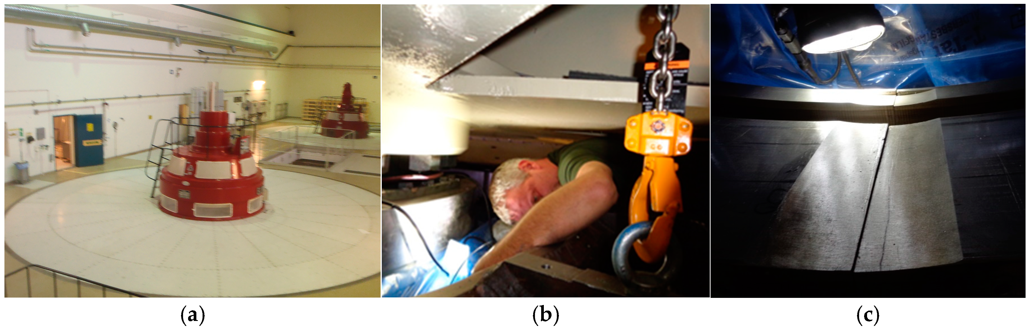
2. Experimentation
3. Numerical Simulation
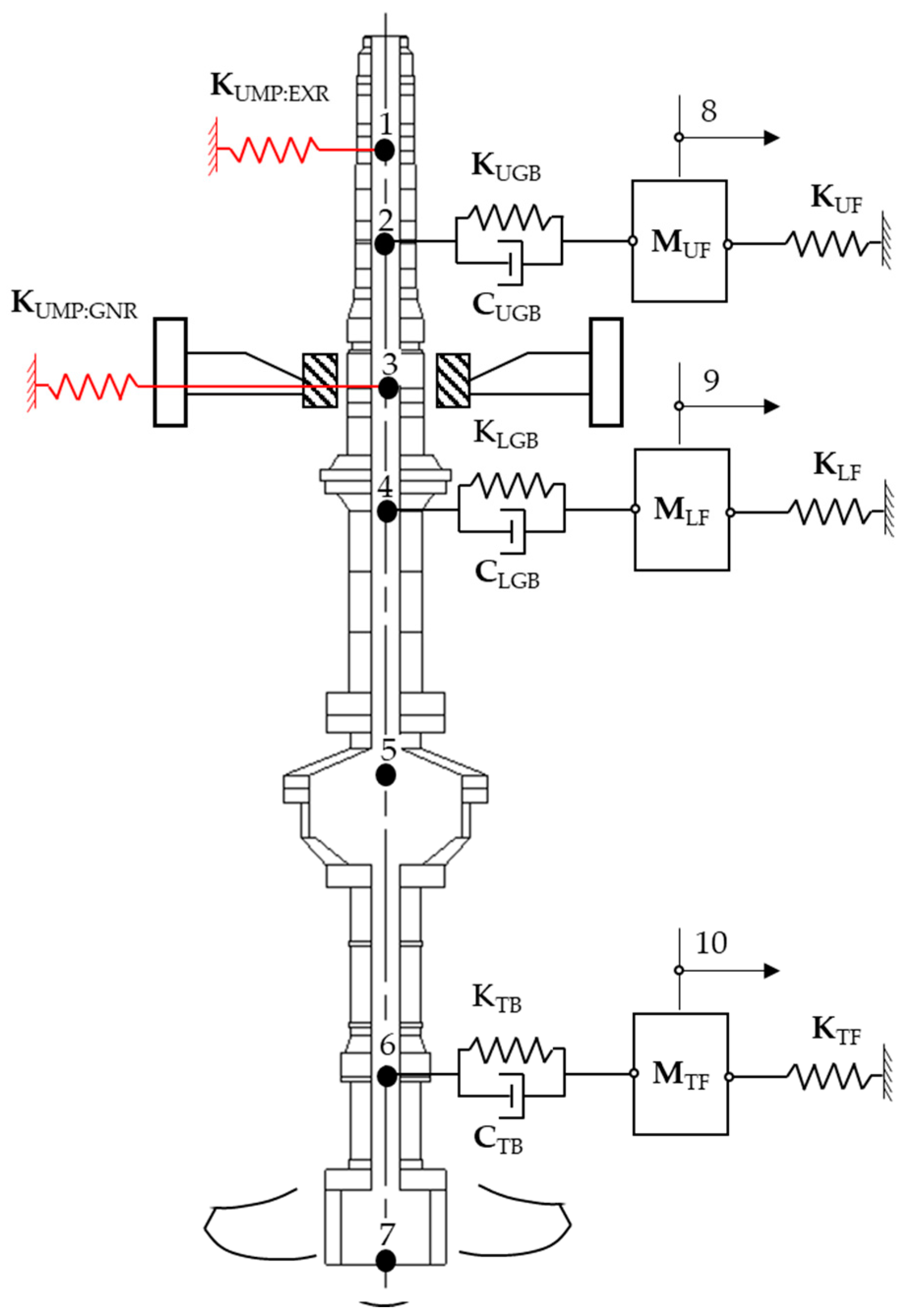
3.1. Rotordynamic Model
3.2. Model Reduction
3.3. Bearing Models
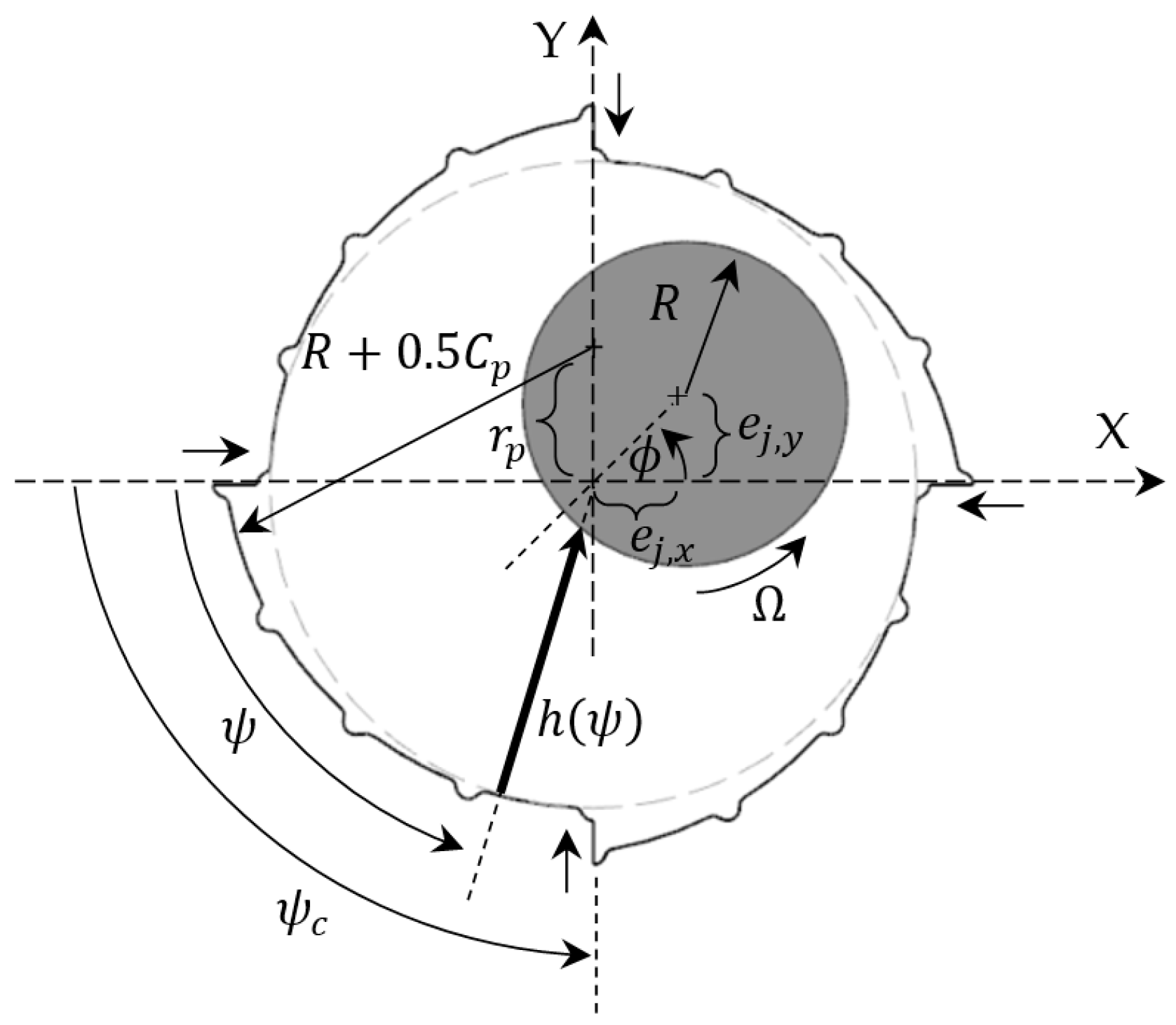
3.3.1. The Fluid Film Force of the UGB and LGB
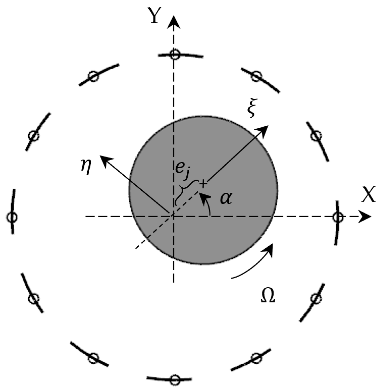
3.3.2. Model of the TPJB
4. Results and Discussion
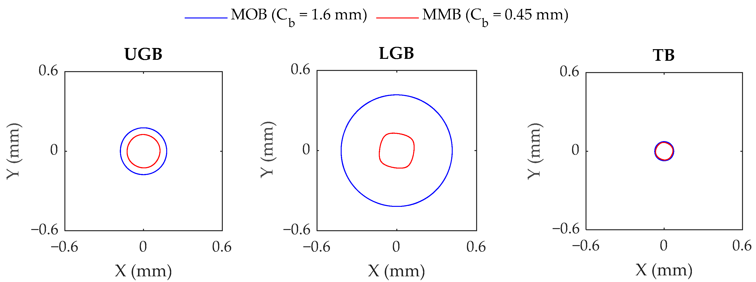
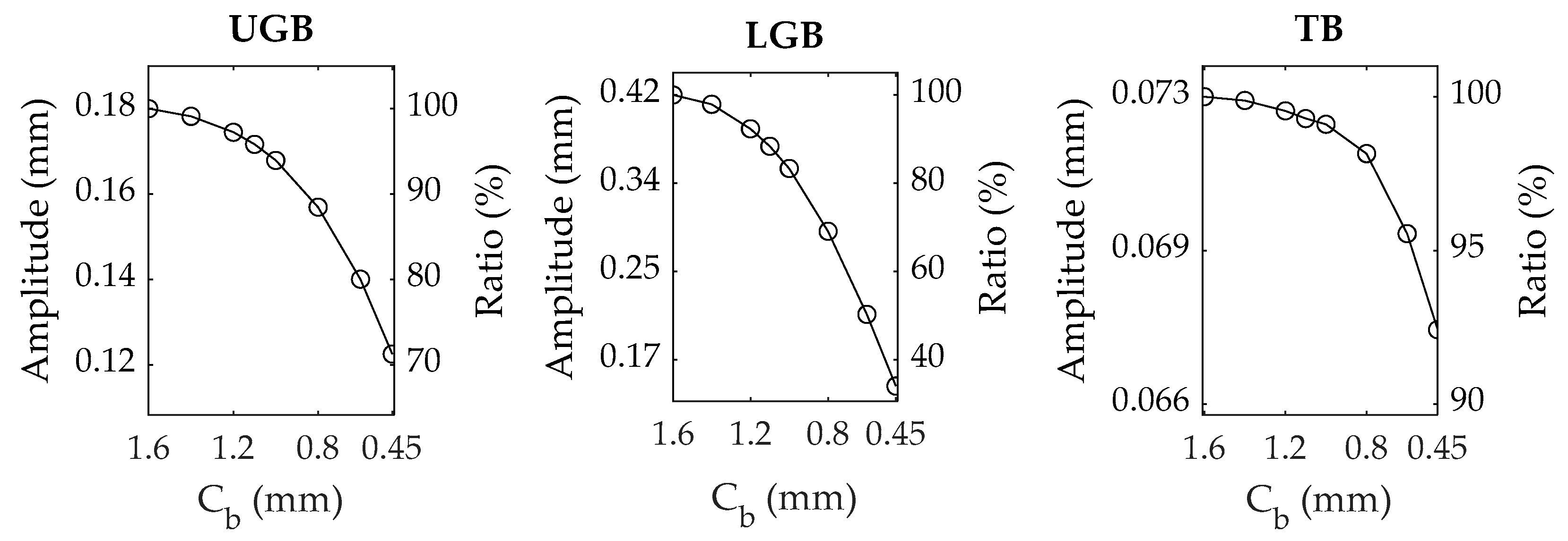
4.1. Simulation Results
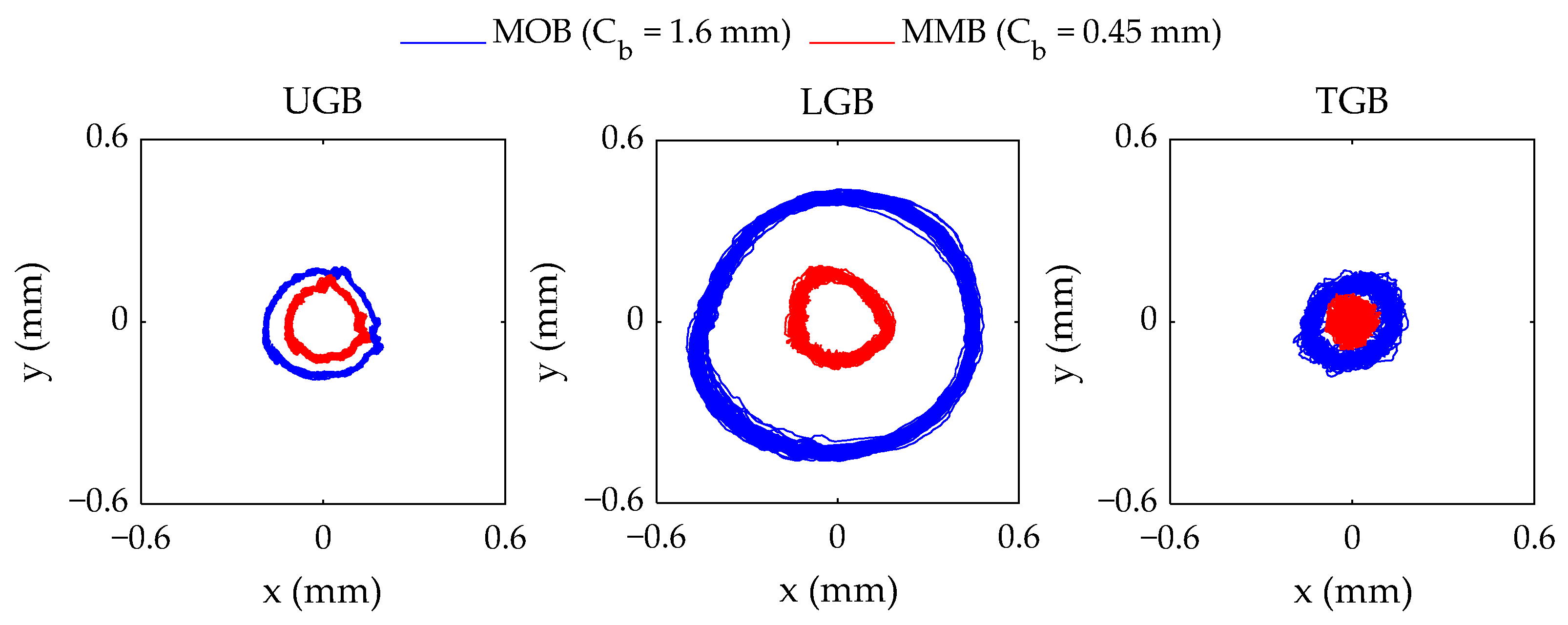
4.2. Vibration Measurement
5. Conclusions
- ▪
- The large bearing clearance of the original LGB allowed for greater shaft movement, resulted in the system’s elevated overall vibration amplitudes, and subjected the UGB and TB to carrying relatively larger loads.
- ▪
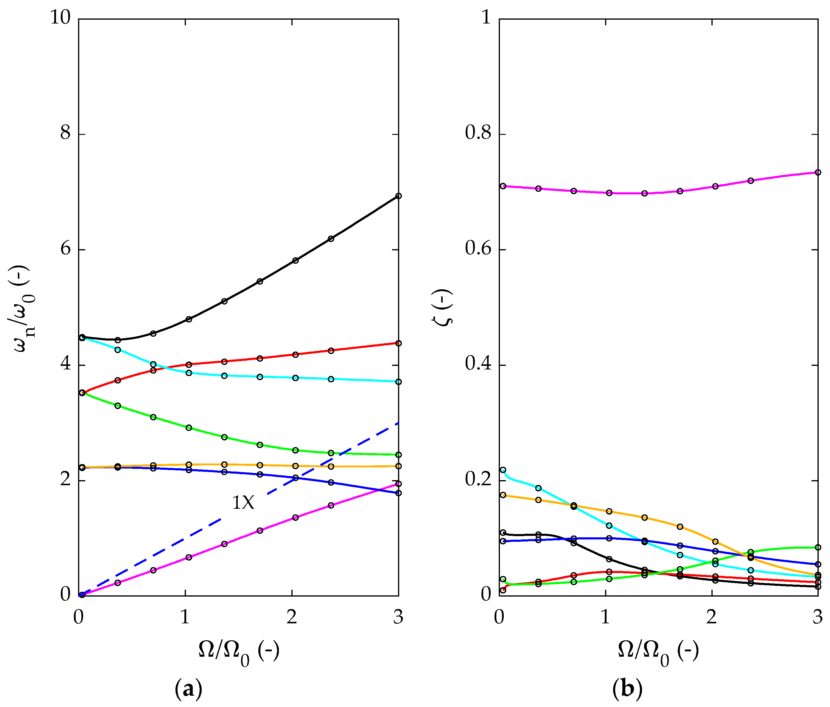
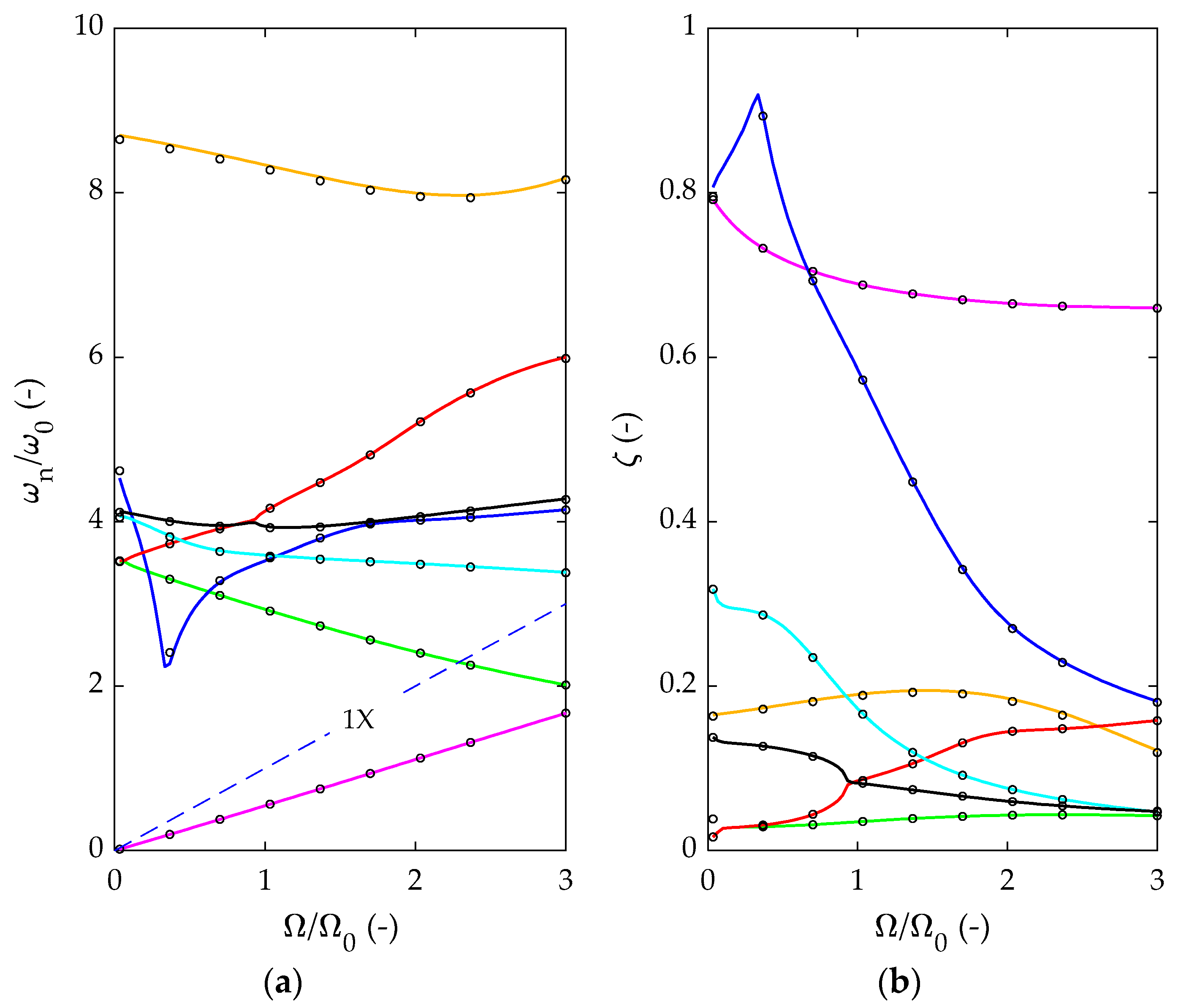
- The design modification increased the second and third modes of the system above the 1X-synchronous line within the speed range, up to the runaway speed, and all the critical speeds were effectively eliminated.
- ▪
- For operation at the nominal speed with UMP, the design modification significantly increased the second and third modes by 73% and 423%, respectively. Similarly, the damping ratios of the first seven modes increased, except for the third mode, which decreased by 40%. However, the damped natural frequency of the third mode increased from 1.6 × to 8.38 × (i.e., 423% increment), and the vibration amplitudes at this frequency were much smaller and were insignificant to producing mechanical failure.
- ▪
- Furthermore, the simulated unbalance responses were reduced by 29%, 66%, and 7% at the UGB and LGB locations, respectively. In the field measurement, the peak-to-peak amplitudes at the three bearing locations were reduced by 35%, 67%, and 47%, respectively.
Author Contributions
Funding
Institutional Review Board Statement
Informed Consent Statement
Data Availability Statement
Acknowledgments
Conflicts of Interest
Nomenclature
| Bearing damping matrix in the local and coordinates (N-s/m) | |
| Bearing damping matrix in the Cartesian coordinates (N-s/m) | |
| , | Diametric bearing clearance, diametric pad clearance (m) |
| C | Damping matrix (N-s/m) |
| , | Maximal/minimal bearing damping coefficient (N-s/m) |
| ,, | Amplitude of the trajectory of the journal center, in the X-axis, and in the Y-axis at the j-node (m) |
| Bearing restoring force vector (N) | |
| , | Bearing force in the X-axis and in the Y-axis (N) |
| , | Unbalance force vector, unbalance force magnitude (N) |
| Force vector of the master nodes (N) | |
| G | Gyroscopic matrix |
| h | The fluid film thickness (m) |
| K | Stiffness matrix (N/m) |
| Bearing stiffness matrix in the Cartesian coordinates (N/m) | |
| , | Maximal/minimal bearing stiffness coefficient (N/m) |
| , | Maximal/minimal equivalent bearing stiffness (N/m) |
| Bearing stiffness matrix in the local and coordinates (N/m) | |
| KUGB, KLGB, KTB | Stiffness of the upper generator guide bearing, lower generator guide bearing, and turbine bearing (N/m) |
| KUF, KLF, KTF | Stiffness of the upper bracket, lower bracket, and turbine bracket (N/m) |
| KUMP:EXR, KUMP:GNR | Magnetic stiffnesses of the exciter and generator (N/m) |
| L | Axial length of the bearing (m) |
| Mass of the generator (i = GNR) or turbine (i = T) (kg) | |
| M | Mass matrix (kg) |
| Number of elements in the axial direction (-) | |
| Number of pads (-) | |
| Number of elements in the circumferential direction (-) | |
| p | Fluid film pressure (Pa) |
| p | Fluid film pressure vector (Pa) |
| q | A vector of displacements (m) and angles (rad) |
| , | A vector of displacements (m) and angles (rad) of the master nodes and the slave nodes |
| Pad preload (m) | |
| r | Normalized damped natural frequency, (-) |
| R | Radius of a journal (m) |
| Transformation matrix (-) | |
| X, Y | Cartesian coordinates with its origin located at the center of the bearing |
| z | Axial coordinate |
| Eccentricity angle (rad) | |
| Circumferential coordinate | |
| Angular displacement measured from the negative X-axis to the minimum film thickness (rad) | |
| Relative eccentricity (-) | |
| ζ | Damping ratio (-) |
| Local coordinate | |
| Lubricant viscosity (mPa·s) | |
| Damped natural frequency (Hz) | |
| Nominal speed (Hz) | |
| Rotor speed (rad/s) | |
| Nominal speed (rad/s) | |
| Runaway speed (rad/s) |
References
- Gupta, B.K. Stability analysis of orthogonally displaced bearings. Wear 1984, 97, 83–92. [Google Scholar]
- Li, D.F.; Choy, K.C.; Allaire, P.E. Stability and Transient Characteristics of Four Multilobe Journal Bearing Configurations. J. Lubr. Technol. 1980, 102, 291–298. [Google Scholar] [CrossRef]
- Rao, T.V.V.L.N.; Biswas, S.; Athre, K. A methodology for dynamic coefficients and nonlinear response of multi-lobe journal bearings. Tribol. Trans. 2001, 44, 111–117. [Google Scholar] [CrossRef]
- Kakoty, S.K.; Kalita, M.; Thivagar, T. Nonlinear time transient stability analysis of multilobe bearings. In Proceedings of the World Tribology Congress III, Washington, DC, USA, 12–16 September 2005. [Google Scholar]
- Allaire, P.E.; Li, D.F.; Choy, K.C. Transient unbalance response of four multilobe journal bearings. J. Lubr. Technol. 1980, 102, 300–306. [Google Scholar] [CrossRef]
- Kumar, A.; Sinhasan, R.; Singh, D.V. Performance characteristics of two-lobe hydrodynamic journal bearings. J. Lubr. Technol. 1980, 102, 425–429. [Google Scholar] [CrossRef]
- Malik, M.; Sinhasan, R.; Chandra, M. Design data for three-lobe bearings. ASLE Trans. 1981, 24, 345–353. [Google Scholar] [CrossRef]
- Sinhasan, R.; Malik, M.; Chandra, M. A comparative study of some three-lobe bearing configurations. Wear 1981, 72, 277–286. [Google Scholar] [CrossRef]
- Someya, T. Journal Bearing Design Data Book; Springer: Berlin/Heidelberg, Germany, 1989. [Google Scholar]
- Malik, M. The Analysis of Symmetric and Tilted Four-Lobed Journal Bearing Configurations. ASLE Trans. 1983, 26, 264–269. [Google Scholar] [CrossRef]
- Malik, M.; Chandra, M.; Sinhasan, R. Performance characteristics of tilted three-lobe journal bearing configurations. Tribol. Int. 1981, 14, 345–349. [Google Scholar] [CrossRef]
- Chauhan, A. Non-Circular Bearings; Springer: Berlin/Heidelberg, Germany, 2016. [Google Scholar]
- Pai, R.; Majumdar, B.C. Stability of submerged four lobe oil journal bearings under dynamic load. Wear 1992, 154, 95–108. [Google Scholar] [CrossRef]
- White, M.F.; Torbergsen, T.; Lumpkin, V.A. Rotordynamic analysis of a vertical pump with tilting-pad journal bearings. Wear 1997, 207, 128–136. [Google Scholar] [CrossRef]
- Smith, D.R.; Woodward, G.M. Vibration analysis of vertical pumps. In Proceedings of the 15th Turbomachinery Symposium, College Station, TX, USA, 10–13 November 1986; pp. 61–68. [Google Scholar]
- Corbo, M.A.; Stefanko, D.B.; Leishear, R.A. Practical use of rotordynamic analysis to correct a vertical long shaft pump’s whirl problem. In Proceedings of the 19th International Pump Users Symposium, Houston, TX, USA, 25–28 February 2002; pp. 107–120. [Google Scholar]
- Leader, M.E.; Conner, K.J.; Lucas, J.D. Evaluating and Correcting Subsynchronous Vibration in Vertical Pumps. In Proceedings of the 26th Texas A&M International Pump Users Symposium, Houston, TX, USA, 16–18 March 2010. [Google Scholar]
- Khatri, R.; Childs, D.W. An Experimental Investigation of the Dynamic Performance of a Vertical-Application Three-Lobe Bearing. J. Eng. Gas Turbines Power 2015, 137, 042504. [Google Scholar] [CrossRef]
- ISO 1941-1; Mechanical Vibration—Balance Quality Requirements for Rotors in a Constant (rigid) State—Part 1: Specification and Verification of Balance Tolerances. ISO: Geneva, Switzerland, 2003.
- Friswell, M.I.; Garvey, S.D.; Penny, J.E.T. Model reduction using dynamic and iterated IRS techniques. J. Sound Vib. 1995, 186, 311–323. [Google Scholar] [CrossRef]
- Falkenhagen, G.L.; Gunter, E.J.; Schuller, F.T. Stability and Transient motion of a vertical three-lobe bearing system. J. Eng. Ind. 1972, 94, 665–677. [Google Scholar] [CrossRef]
- Thiery, F.; Gantasala, S.; Aidanpaä, J.O. Numerical evaluation of multilobe bearings using the spectral method. Adv. Mech. Eng. 2017, 9, 1–10. [Google Scholar] [CrossRef]
- Booker, J.F.; Huebner, K.H. Application of finite element methods to lubrication: An engineering approach. J. Lubr. Technol. 1972, 94, 313–323. [Google Scholar] [CrossRef]
- Benti, G.B.; Rondon, D.; Gustavsson, R.; Aidanpaä, J.O. Numerical and Experimental Study on the Dynamic Bearing Properties of a Four-Pad and Eight-Pad Tilting Pad Journal Bearings in a Vertical Rotor. J. Energy Resour. Technol. ASME 2022, 144, 011304. [Google Scholar] [CrossRef]
- Rotordynamic Seal Research. Available online: https://www.rda.guru/ (accessed on 10 November 2023).

| Description (Unit) | Exciter | Generator | Runner |
|---|---|---|---|
| Mass (kg) | 3500 | 1.51 × 10⁵ | 53,600 |
| Polar moment of inertia (kg·m2) | 3500 | 1.38 × 10⁶ | 56,400 |
| Diametral moment of inertia (kg·m2) | 1750 | 6.88 × 10⁵ | 44,300 |
| Unbalanced magnetic pull (MN/m) | 26.62 | 170 | |
| Young’s modulus (N/m2) | 2 × 10¹¹ | ||
| UGB | LGB | TB | ||
|---|---|---|---|---|
| Geometry | ||||
| Type | Sleeve bearing | Sleeve bearing | Four-lobe bearing | TPJB |
| Journal diameter (mm) | 1050 | 2450 | 2450 | 1100 |
| Number of segments/pads | - | - | 4 | 12 |
| Dia. bearing clearance (mm) | 0.6 | 1.6 | 0.45 | 0.35 |
| Offset ratio (-) | 0.5 | 0.5 | 1 | 0.6 |
| Preload ratio (-) | 0 | 0 | 0.718 | 0.65 |
| Axial length (mm) | 345 | 185 | 185 | 180 |
| Arc length (degree) | - | - | 85 | 18.5 |
| Material | ||||
| Surface pad material | Babbitt | |||
| Density (kg/m3) | 7280 | |||
| Radial thickness (mm) | 5 | 6 | 6 | 3 |
| Base pad material | Steel | |||
| Density (kg/m3) | 7780 | |||
| Radial thickness (mm) | 65 | 100 | 100 | 52 |
| Lubricant Properties | ||||
| Type | Turboway 68 | |||
| Inlet oil temperature (°C) | 60 | |||
| Oil supply pressure (MPa) | 0.1 | |||
| Density (kg/m3) | 880 | |||
| Viscosity at 40 °C (mPa·s) | 61 | |||
| Viscosity at 100 °C (mPa·s) | 7.7 | |||
| Bracket | UF | LF | TF | |
| Mass (kg) | 10 × 103 | 10 × 103 | 10 × 103 | |
| Stiffness (N/m) | 3 × 10⁸ | 1.87 × 10⁹ | 2.2 × 10⁹ | |
| Normalized Damped Natural Frequency, r (-) | |||||||
|---|---|---|---|---|---|---|---|
| Cb (mm) | 1 | 2 | 3 | 4 | 5 | 6 | 7 |
| 1.6 (MOB) | 0.65 | 1.53 | 1.6 | 2.75 | 3.73 | 3.87 | 4.65 |
| 1.4 | 0.65 | 1.59 | 1.65 | 2.75 | 3.71 | 3.87 | 4.63 |
| 1.2 | 0.65 | 1.64 | 1.92 | 2.75 | 3.67 | 3.87 | 4.59 |
| 1.1 | 0.63 | 1.63 | 1.86 | 2.75 | 3.68 | 3.87 | 4.6 |
| 1 | 0.63 | 1.76 | 5.03 | 2.75 | 3.59 | 3.87 | 4.43 |
| 0.8 | 0.61 | 1.96 | 7.89 | 2.75 | 3.61 | 3.87 | 4.33 |
| 0.6 | 0.57 | 2.25 | 8.3 | 2.76 | 3.62 | 3.86 | 4.24 |
| 0.45 (MMB) | 0.54 (−16.9%) * | 2.65 (+73%) * | 8.38 (+423%) * | 2.77 (+0.7%) * | 3.56 (−4.6%) * | 3.86 (−0.3%) * | 4 (−14%) * |
| Damping Ratio, ζ (-) | |||||||
|---|---|---|---|---|---|---|---|
| Cb (mm) | 1 | 2 | 3 | 4 | 5 | 6 | 7 |
| 1.6 (MOB) | 0.303 | 0.369 | 0.252 | 0.032 | 0.142 | 0.061 | 0.08 |
| 1.4 | 0.323 | 0.387 | 0.486 | 0.033 | 0.15 | 0.062 | 0.096 |
| 1.2 | 0.377 | 0.385 | 0.643 | 0.034 | 0.158 | 0.064 | 0.115 |
| 1.1 | 0.348 | 0.387 | 0.583 | 0.035 | 0.156 | 0.064 | 0.109 |
| 1 | 0.454 | 0.384 | 0.696 | 0.036 | 0.149 | 0.067 | 0.132 |
| 0.8 | 0.524 | 0.420 | 0.290 | 0.039 | 0.133 | 0.071 | 0.129 |
| 0.6 | 0.568 | 0.495 | 0.179 | 0.045 | 0.139 | 0.074 | 0.147 |
| 0.45 (MMB) | 0.589 (+94%) * | 0.722 (+95%) * | 0.151 (−40%) * | 0.053 (+65%) * | 0.160 (+13%) * | 0.078 (+28%) * | 0.151 (+89%) * |
| Cases | UGB | LGB | TB | |||
|---|---|---|---|---|---|---|
| X (mm) | Y (mm) | X (mm) | Y (mm) | X (mm) | Y (mm) | |
| 0 MW 0 kV | 0.11 (0.13) | 0.12 (0.12) | 0.1 (0.2) | 0.1 (0.2) | 0.04 (0.11) | 0.04 (0.11) |
| 0 MW 12.4 kV | 0.23 (0.36) | 0.23 (0.35) | 0.3 (0.92) | 0.3 (0.92) | 0.15 (0.29) | 0.15 (0.28) |
| 13 MW | 0.23 (0.36) | 0.22 (0.36) | 0.31 (0.91) | 0.3 (0.91) | 0.1 (0.29) | 0.1 (0.29) |
| 26 MW | 0.21 (0.33) | 0.21 (0.33) | 0.3 (0.82) | 0.29 (0.82) | 0.04 (0.25) | 0.04 (0.24) |
| 38 MW | 0.2 (0.32) | 0.2 (0.31) | 0.29 (0.82) | 0.29 (0.81) | 0.04 (0.19) | 0.04 (0.18) |
| 52 MW | 0.19 (0.33) | 0.19 (0.32) | 0.28 (0.83) | 0.26 (0.82) | 0.04 (0.15) | 0.04 (0.14) |
| Cases | UGB | LGB | TB | |||
|---|---|---|---|---|---|---|
| X (mm) | Y (mm) | X (mm) | Y (mm) | X (mm) | Y (mm) | |
| 0 MW 0 kV | 0.02 (0.01) | 0.02 (0.01) | <0.01 (0.01) | <0.01 (0.01) | <0.01 (0.01) | <0.01 (0.01) |
| 0 MW 12.4 kV | 0.025 (0.075) | 0.02 (0.07) | 0.03 (0.01) | 0.03 (0.01) | <0.01 (0.01) | <0.01 (0.01) |
| 13 MW | 0.03 (0.07) | 0.025 (0.07) | 0.03 (0.02) | 0.03 (0.02) | <0.01 (0.02) | <0.01 (0.02) |
| 26 MW | 0.025 (0.065) | 0.02 (0.06) | 0.03 (0.015) | 0.03 (0.015) | <0.01 (0.015) | <0.01 (0.015) |
| 38 MW | 0.03 (0.06) | 0.02 (0.055) | 0.025 (0.015) | 0.025 (0.015) | <0.01 (0.01) | <0.01 (0.01) |
| 52 MW | 0.02 (0.06) | 0.02 (0.06) | 0.025 (0.01) | 0.025 (0.01) | <0.01 (0.01) | <0.01 (0.01) |
Disclaimer/Publisher’s Note: The statements, opinions and data contained in all publications are solely those of the individual author(s) and contributor(s) and not of MDPI and/or the editor(s). MDPI and/or the editor(s) disclaim responsibility for any injury to people or property resulting from any ideas, methods, instructions or products referred to in the content. |
© 2024 by the authors. Licensee MDPI, Basel, Switzerland. This article is an open access article distributed under the terms and conditions of the Creative Commons Attribution (CC BY) license (https://creativecommons.org/licenses/by/4.0/).
Share and Cite
Benti, G.B.; Aidanpää, J.-O.; Gustavsson, R. Cost-Effective Design Modification of a Sleeve Bearing with Large Bearing Clearance. Appl. Sci. 2024, 14, 1214. https://doi.org/10.3390/app14031214
Benti GB, Aidanpää J-O, Gustavsson R. Cost-Effective Design Modification of a Sleeve Bearing with Large Bearing Clearance. Applied Sciences. 2024; 14(3):1214. https://doi.org/10.3390/app14031214
Chicago/Turabian StyleBenti, Gudeta Berhanu, Jan-Olov Aidanpää, and Rolf Gustavsson. 2024. "Cost-Effective Design Modification of a Sleeve Bearing with Large Bearing Clearance" Applied Sciences 14, no. 3: 1214. https://doi.org/10.3390/app14031214
APA StyleBenti, G. B., Aidanpää, J.-O., & Gustavsson, R. (2024). Cost-Effective Design Modification of a Sleeve Bearing with Large Bearing Clearance. Applied Sciences, 14(3), 1214. https://doi.org/10.3390/app14031214