Article

A Precise Modeling Method for PMSM Servo System of Spacecraft

1
Department of Electrical Engineering, Tsinghua University, Beijing 100084, China
2
Beijing Institute of Mechanical Equipment, Beijing 100854, China
*
Author to whom correspondence should be addressed.
Appl. Sci. 2024, 14(3), 1161; https://doi.org/10.3390/app14031161
Submission received: 19 December 2023 / Revised: 23 January 2024 / Accepted: 28 January 2024 / Published: 30 January 2024

Abstract

:
Permanent magnet synchronous motor (PMSM) servo system is the control and execution mechanism of spacecraft, and its precise modeling is of great practical significance for improving the performance of the spacecraft. A comprehensive model considering elasticity, backlash, and friction was established based on the structural composition and transmission characteristics of spacecraft. Firstly, an elastic-dead zone model was established based on the transmission characteristics, with two mass elastic and gear backlash dead zones as the main features. Then, an improved LuGre friction model was established that considers the effects of vibration and environmental temperature, and the three models were organically combined. Finally, a method for identifying nonlinear parameters of the system using sinusoidal sweep and the least squares method was proposed, and the accuracy of the constructed model was verified. The experiment shows that the error of the simulation results is consistent with the experimental results. This method can precisely obtain the servo system model, providing theoretical support for control method research.

1. Introduction

The permanent magnet synchronous motor (PMSM) servo system is the control and execution mechanism of spacecraft, and its precise modeling is the foundation of control method research, which is of great practical significance for improving the performance of the spacecraft. The modeling methods for spacecraft servo systems mainly include mechanism modeling and experimental modeling. Early modeling methods decomposed the servo system into multiple independent subsystems and submodules, established mechanism equations of the system using existing theories, and optimized the performance through repeated parameter iterations [1]. This modeling method fails to fully reflect the complex characteristics of cross coupling in servo systems, and the iteration time is relatively long, making the research process time-consuming and laborious. With the development of computer technology, the combination of simulation and experimentation in experimental modeling can achieve precise digital simulations of complex servo systems, effectively improving research efficiency.
Due to the extremely fast flight speed, complex flight environment and its own unique structure, the PMSM servo system of spacecraft has the complex control characteristics of fast time-varying, strong nonlinear, coupling and uncertainty. As a result, the traditional rigid body hypothesis is no longer valid, and the influence of nonlinear factors such as elasticity, backlash and friction under comprehensive environment such as temperature change, wind tunnel and vibration should be fully considered [2,3,4]. There have been relevant studies on the precise modeling of nonlinear factors in PMSM servo systems. Ref. [5] uses the nonlinear differential equation of the flight control actuators to represent its servo system model, thereby improving the performance of the steering gear stiffness. But the fine structure inside the servo system is not reflected. In [6], a function interpolation method based on Chebyshev approximation theory to approximate the kinematic model is proposed, for optimizing the positioning error of the servo system of a flexible joint robotic arm. Compared with the pseudo stiffness modeling method, this method improves the positioning accuracy by an order of magnitude. The singular perturbation method is used in [7] to decouple the dynamic equations of flexible robotic arms, obtaining two subsystems: rigid robot motion and flexible linkage vibration. On this basis, a disturbance observer is designed to suppress the elastic resonance of the flexible robotic arm. An n-dimensional discrete model of a flexible robotic arm servo system is established in [8]. The article studies the full state feedback neural network controller of the servo system and achieves trajectory tracking and vibration suppression. Ref. [9] presents an eigenvalue method to analyze limit cycles in an electric dual-mass drive system with backlash nonlinearity, demonstrating its efficacy across diverse control structures and nonlinear control plants.
Backlash is a common problem in the transmission servo system. To address the issues of vibration suppression and torque limitation in servo systems with backlash, a novel torque compensator is proposed in [10] to approximate the system to an inertial rigid system. This method reduces the mechanical vibration of the system under different inertia and torque conditions, ensuring control accuracy and arbitrary torque limitation. The output tracking problem of gear transmission servo systems with backlash nonlinearity is studied in [11]. In order to overcome the nonlinear and non-differentiable characteristics of the backlash, a detailed static softening process is proposed and a backstepping control algorithm is designed to avoid limit cycles caused by backlash nonlinearity. In [12], the prediction and suppression of limit cycle oscillations in a two-mass system with nonlinear backlash is studied. In order to compensate for the nonlinearity of backlash, a state feedback controller is designed to reduce the impact, eliminate the limit cycle oscillation and improve the accuracy of position control. A linear and a nonlinear method of ESO for a two-mass system with ADRC speed control loop of the motor side are proposed in [13]. The performance of the two approaches, such as damping of the torsional vibration and influence of backlash width, is compared. Ref. [14] presents an adaptive model predictive control to eliminate the effects of clearance and coulomb dry friction, which is proved to be correct in servo position tracking simulation. In [15], the influence of the backlash and friction is analyzed by a description function method and simulation. A comprehensive two-mass full-closed-loop system incorporating both backlash and friction is also constructed.
The friction models of real systems are usually discontinuous or piecewise continuous, which is not conducive to the actual realization of the control system. Some continuous friction models have been proposed [16], such as Stribeck friction model, LuGre friction model, etc. For nonlinear servo systems with friction compensation, a continuous friction model is adopted to obtain the friction dynamics [17]. In order to suppress the dynamic disturbance, an adaptive parameter estimation method is proposed to identify the friction model parameters, which improves the system’s disturbance resistance and tracking accuracy. The servo system of continuous friction model [18] establishes a nonlinear parameterized friction model and uses the nonlinear least squares method to estimate parameters of the model, such as viscosity coefficient and the Coulomb coefficient. Based on the established friction model, a backstepping controller is designed. Ref. [19] proposes linearization control for servo systems with friction based on the LuGre model and gives a high-gain closed-loop speed control method to identify the dynamic parameters of the LuGre model. An experimental friction model for the PMSM servo system is proposed in [20]. A control system with maximum bandwidth is designed using the proposed friction model and analysis results, which improves the dynamic response of the system. Ref. [21] derives a modified LuGre friction model to compensate for dynamic friction behaviors. A discontinuous projection mapping is employed to enhance the stability of parameter adaptation during the learning process. In [22], a new static compensation method combined with a Stribeck model of fuzzy low-pass filter is proposed to study the friction compensation of the PMSM servo system, which is to solve the friction degradation problem of speed and position tracking accuracy in PMSM servo systems.
Due to the special application scenario of the research object, the relevant literature is less published, or focuses on a certain direction of the electrical or mechanical system. The above research has studied the modeling mechanism and action rules of nonlinear factors such as elasticity, backlash, and friction in servo systems from different perspectives, and has improved the performance to a certain extent. However, these modeling methods did not consider the relationship between elasticity and resonances, the interaction between elasticity and backlash, and the influence of the external environment on friction [23,24]. Furthermore, it is not possible to fully and accurately characterize the PMSM servo system through the study of single and partially coupled factors. In this regard, this paper proposes a modeling method that considers elasticity, backlash, and friction characteristics. The elastic dead zone model and the improved LuGre friction model considering environmental effects are organically combined to form a high-precision PMSM servo system model through simulation analysis and experimental verification. The main contributions of this paper are as follows:
(1)
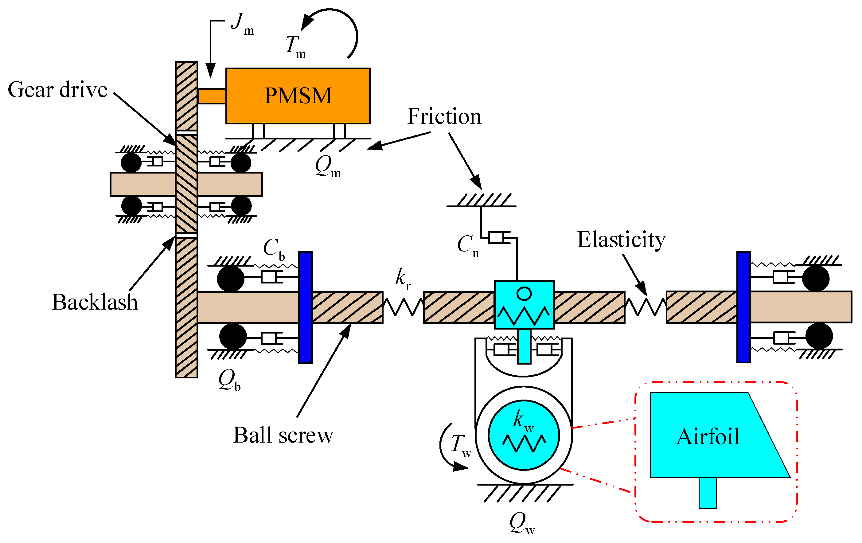
From the perspective of multi-disciplinary modeling, a PMSM servo system model for spacecraft was established for the first time, which includes three nonlinear factors: elasticity, backlash, and friction. This model comprehensively characterizes the influence mechanism of nonlinear factors on the PMSM servo system.
(2)
The backlash features were integrated into the elasticity to form an elastic dead zone model. Besides, considering the effects of impact vibration and environmental temperature on the LuGre friction model, some improvements were made to it.
(3)
By analyzing the difference between simulation and experimental data, a high-precision PMSM servo system model was formed, which can provide the theoretical basis for control method research and system performance optimization.
The remainder of this article is organized as follows. In Section 2, the PMSM servo system is introduced. The details of nonlinear precise modeling of elasticity, clearance, and friction characteristics are proposed in Section 3. Subsequently, the experimental testing and validation are presented in Section 4. And finally, Section 5 concludes this paper.

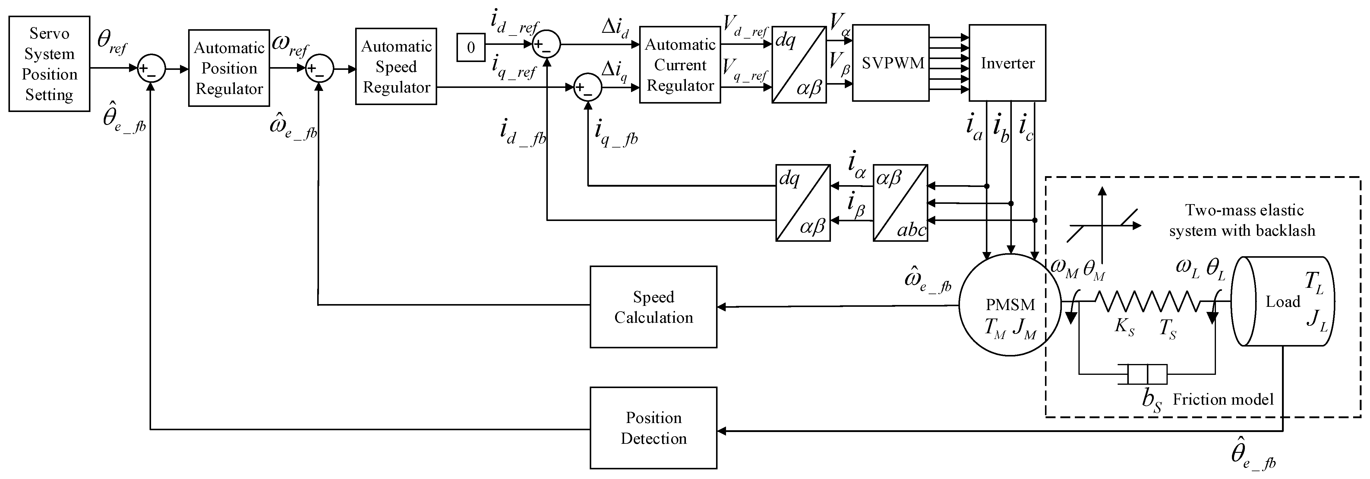
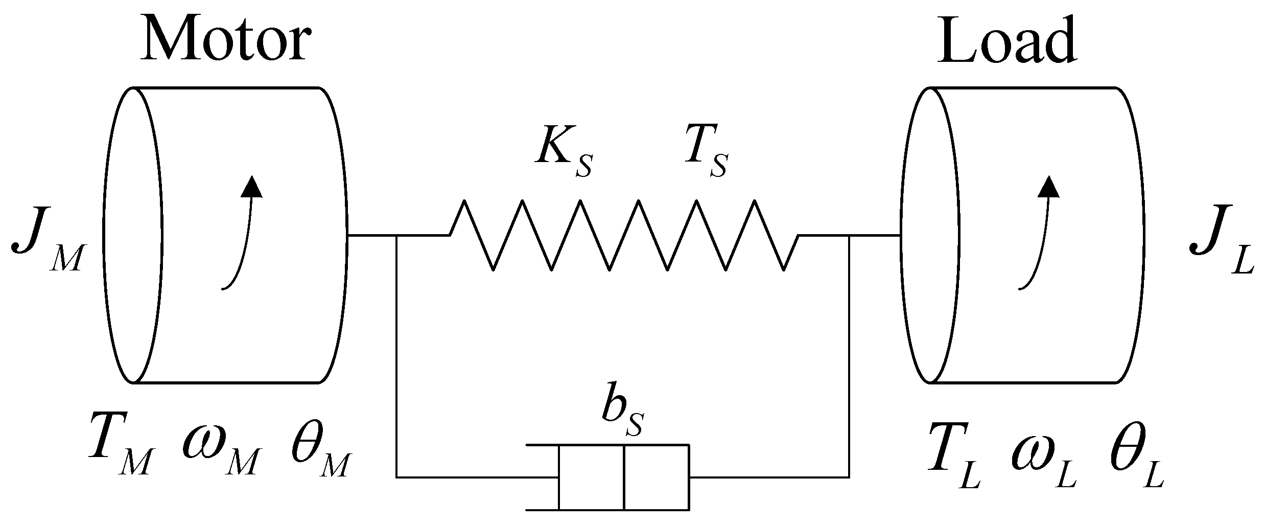
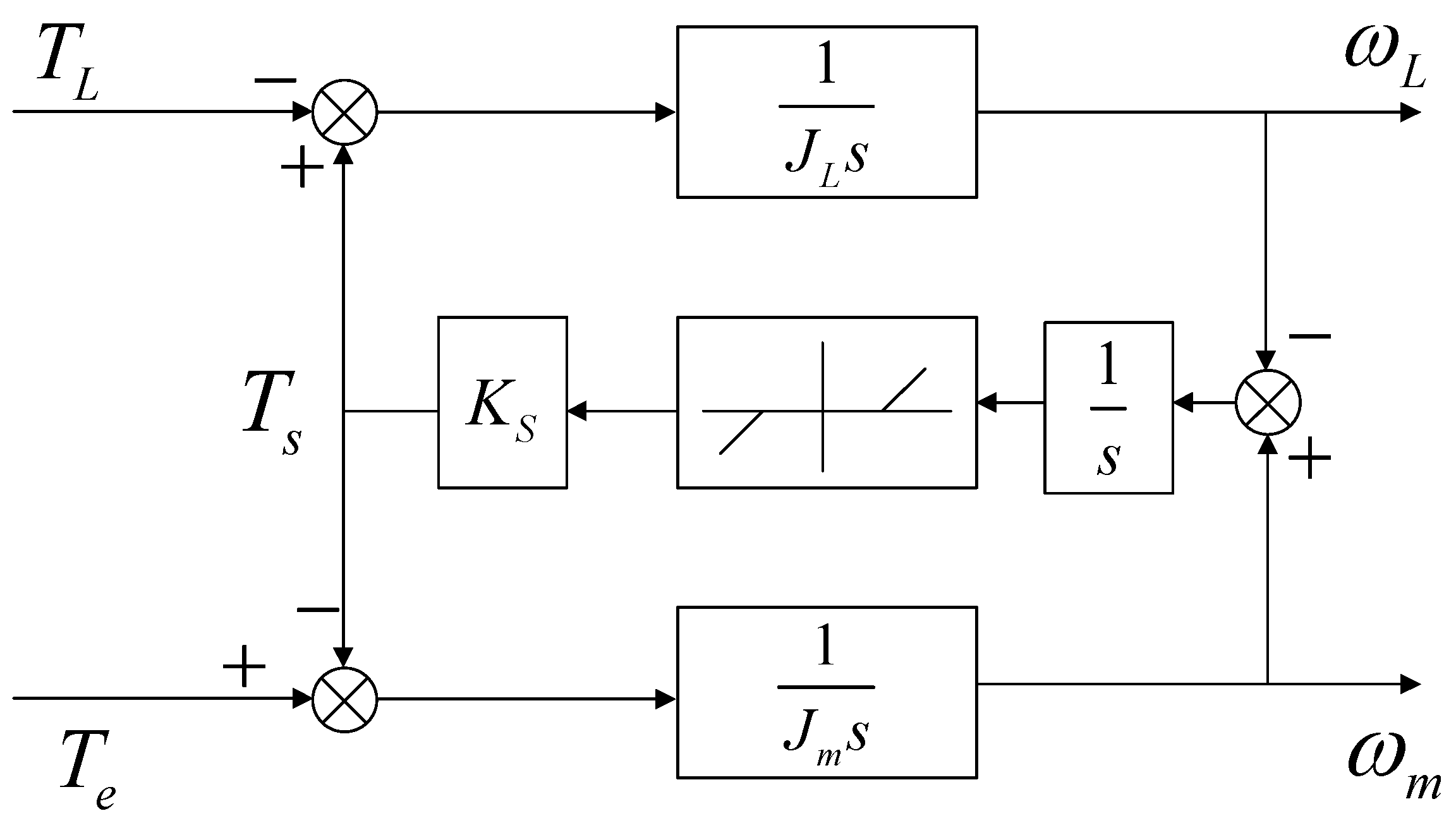
2. PMSM Servo System

The structure of the PMSM servo system for spacecraft is shown in Figure 1. PMSM drives the ball screw to rotate through gear transmission, thereby controlling the deflection angle of the wing. In gear meshing, ball screw and mechanical transmission connections, there are many nonlinear factors such as elasticity, backlash, and friction, which come from gear clearance, meshing stiffness, torsional and axial elasticity of ball screw, wing damping, etc. The existence of these nonlinear factors seriously affects the performance of the PMSM servo system and should be fully considered in precise modeling.
The structural diagram of the whole servo system is shown in Figure 2. The vector control is carried out considering the friction model and the two-mass elastic system with backlash.
The servo system of the spacecraft uses PMSM as the executive motor, and its dynamic equation is as follows:
{ d x d t = A x + B u y = C x }
where x = [ ω m T L ] , ω m is the mechanical angular speed of the motor, T L is the load torque of the motor; A = [ B m J m 1 J m 0 0 ] , B m is the viscous friction coefficient, J m is the rotational inertia of the motor; B = [ 1 J m 0 ] ; C = ; u = T e , T e is the electromagnetic torque of the motor; y = ω m .

3. Nonlinear Precise Modeling

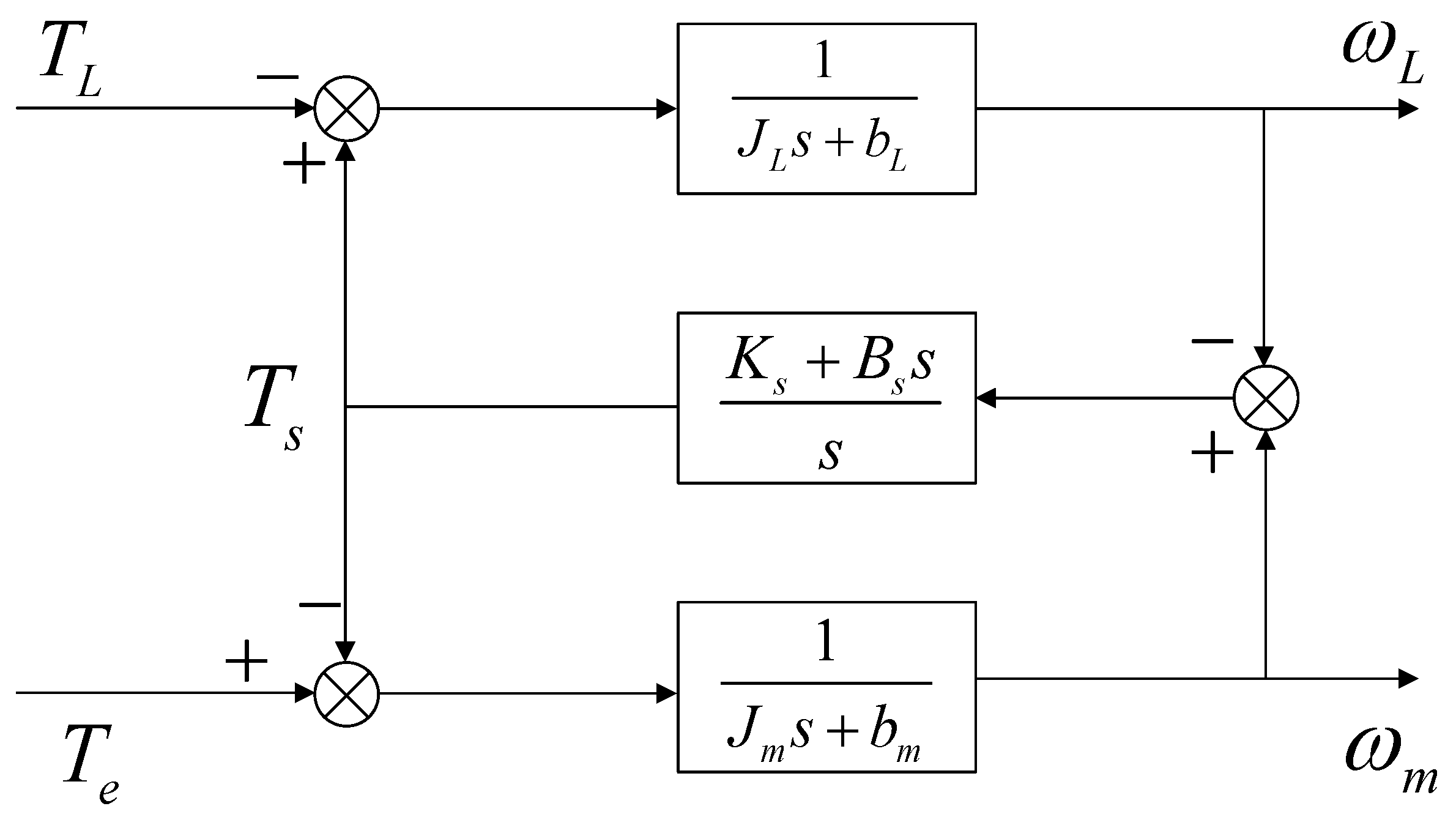
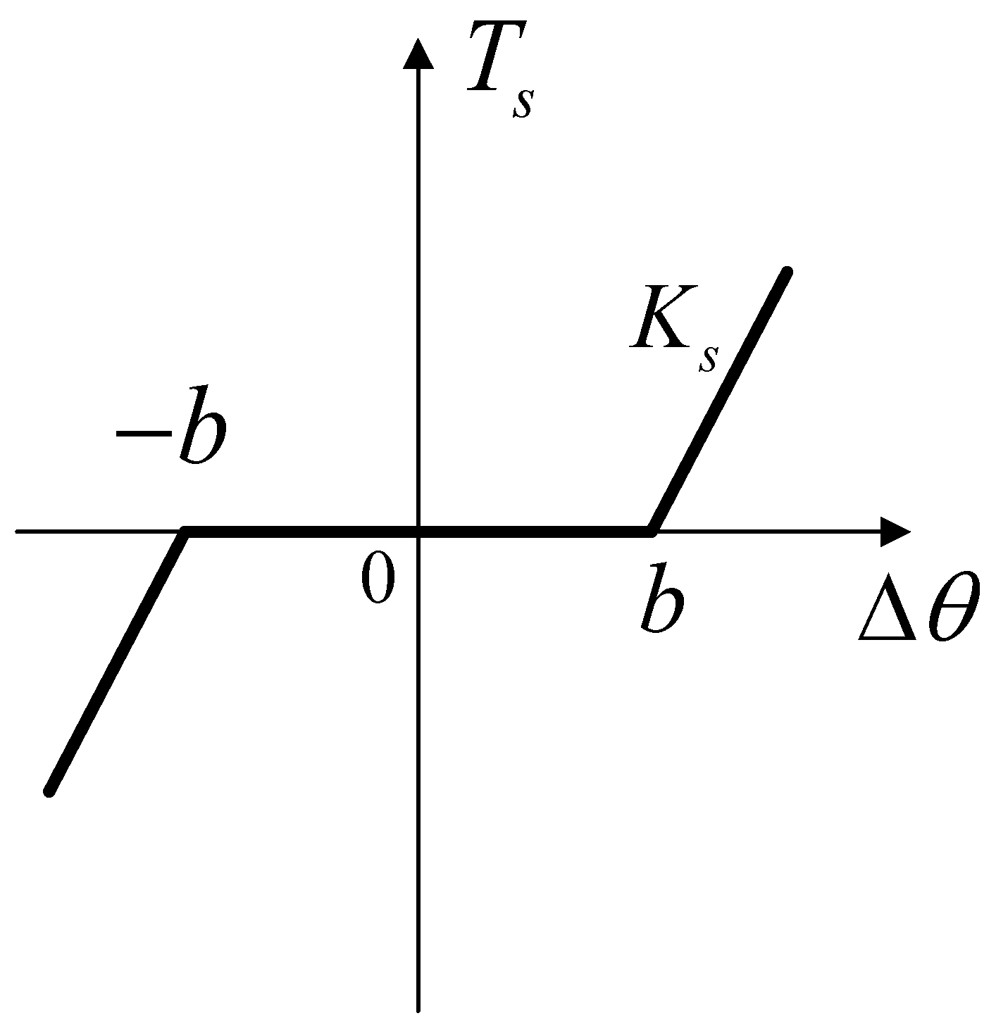
3.1. Modeling of Elastic Characteristics

The elastic characteristics of the spacecraft servo system can be represented by the two-mass elastic model shown in Figure 3. The transmission link connects the motor and the actuator, with a certain stiffness K s and damping coefficient B s , When the transmission shaft undergoes torsional deformation, a torque T s is generated. The electromagnetic torque T e of the motor and the torsional torque T s of the transmission shaft act together on the motor shaft with a rotational inertia of J M and a damping coefficient of B M . The equivalent rotational inertia of the actuator is J L , and the damping coefficient is B L . The torsional torque T s of the transmission shaft and the load torque T L act together on the actuator, ultimately determining the load speed.
Based on the theoretical analysis above, the system dynamic equation is established as follows:
J m θ ¨ m = T e B m θ ˙ m T s J L θ ¨ L = T s B L θ ˙ L T L T s = K s ( θ m θ L ) + B s ( θ ˙ m θ ˙ L ) ω m = θ ˙ m ω L = θ ˙ L
By performing the Laplace transform on the above equation, the block diagram of the two-mass elastic system is obtained as shown in Figure 4.

3.2. Backlash Characteristic Modeling

The commonly used backlash models in the control field include the oscillatory model, hysteresis model, and dead-zone model. In electromechanical servo systems, the dead-zone model is widely used to describe the effect of backlash characteristics on the transmission torque. The dead-zone characteristics of the backlash are shown in Figure 5. When the commutation angle is less than b, the presence of the backlash will cause the transmission torque to be 0, and the original torque will be maintained at other times.
The expression of the dead-zone model is
T s = K s ( Δ θ b ) + B s Δ θ ˙ , Δ θ > b 0 , Δ θ b K s ( Δ θ + b ) + B s Δ θ ˙ , Δ θ < b
where T s is the transmission torque; K s is the equivalent stiffness of the transmission link; B s is the damping coefficient of the transmission link; Δ θ = θ m θ L , b is the half-width of the backlash.
Due to the small damping in the system, its influence can be neglected. Combining Equations (2) and (3), the Laplace transform of the elastic-dead-zone model can be obtained as
J m θ m s 2 = T e T s J L θ L s 2 = T s T L T s = K s ( θ m θ L b ) , θ m θ L > b 0 , b < θ m θ L < b K s ( θ m θ L + b ) , θ m θ L < b ω m = θ m s ω L = θ L s
From this, the block diagram of the two-mass elastic system with backlash can be obtained as shown in Figure 6.
Since the equivalent stiffness K s directly affects the resonance frequency of the system, the calculation of the equivalent stiffness K s is also crucial in modeling. The meshing process of the transmission system is shown in Figure 7a, and its local magnification is shown in Figure 7b. Within the entire meshing region, there will be one single-tooth meshing area and two double-tooth meshing areas. At any given moment during the meshing process, as shown in Figure 7c, the total deformation of a pair of meshed gears is the sum of the elastic deformations of the driving and driven gears, given by
δ s = δ p + δ g
Based on the theoretical relationship between stiffness and elastic deformation, and Equation (5), the expression for the stiffness of single-tooth meshing is obtained as
K s = 1 δ s = 1 δ p + δ g = k p k g k p + k g
The symbols δ p and δ g represent the deformations of the driving and driven gears, while k p and k g represent the stiffness of the driving and driven gears, respectively.
According to the principle of stiffness superposition, the stiffness K m s of double-tooth meshing can be obtained by superimposing the stiffness of single-tooth meshing, as shown in Figure 7d. When transitioning from single-tooth meshing to double-tooth meshing, the stiffness undergoes a step change. The meshed gears are in a state of separation and contact repeatedly during the transmission process, making the deformation of the gears exhibit strong nonlinear characteristics.
Figure 7. Time-varying mesh stiffness of the gear. (a) Gear meshing process; (b) Local magnification; (c) Single pair gear deformation; (d) Stiffness superposition.
Applsci 14 01161 g007

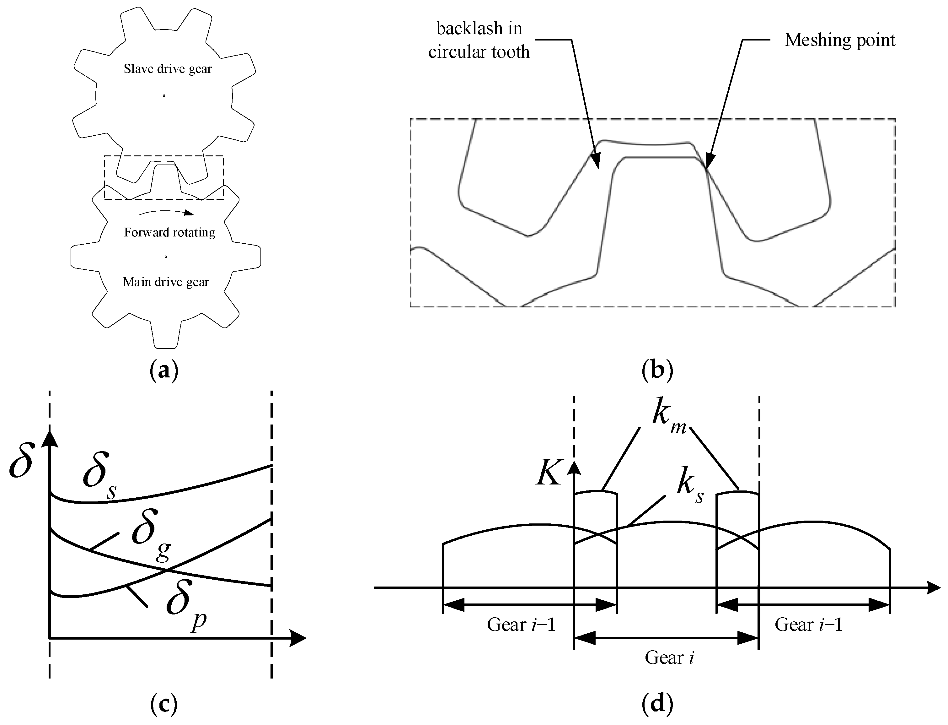
3.3. Friction Characteristics Modeling

Friction characteristics can be divided into static friction and dynamic friction according to their motion characteristics. In actual systems, multiple types of friction forces usually coexist, such as the Stribeck model. The actual operating state of the servo system may change dynamically in real time under different operating conditions. Considering the static and dynamic characteristics of friction, the LuGre friction model can comprehensively characterize the dynamic and static processes of the frictional link among various friction models and is currently one of the most widely studied and applied friction models. Compared with the Stribeck model, the LuGre model can more accurately describe the friction change under dynamic velocity.
This paper characterizes the friction characteristics of spacecraft servo systems based on their application characteristics. The friction force is influenced by multiple factors and parameters, and the environment and operating conditions are complex and variable. The LuGre friction model is adopted to represent the friction characteristics of the servo system. The LuGre friction model can be expressed as
F f = σ 0 z + σ 1 d z d t + σ 2 θ ˙ F z f = σ 0 z + σ 1 d z d t F v f = σ 2 θ ˙ d z d t = θ ˙ θ ˙ g ( θ ˙ ) z σ 0 g ( θ ˙ ) = F c + ( F s F c ) exp ( θ ˙ / θ ˙ s ) 2
where F f represents the LuGre friction force; F z f represents the friction force associated with the mane offset; F v f represents the viscous friction force related to the velocity; θ ˙ is the velocity of the actuator; σ 0 , σ 1 , σ 2 are stiffness coefficient, damping coefficient and viscous friction coefficient, respectively; z is the average offset between the bristles; F c represents Coulomb friction force; F s represents maximum static friction force; θ ˙ s is the Stribeck velocity.
The model shown in Equation (7) only considers the case where the operating conditions are relatively stable and does not take into account the impact of external environmental changes. Spacecraft servo systems operate in a wide temperature range of [−55 °C, 180 °C], while being subjected to unknown airflow disturbances such as gusts and turbulence. When spacecraft servo systems experience vibration, shock, or acceleration/deceleration, the contact between the bristles in the friction model changes, thereby affecting the magnitude of friction force. Selecting μ as the influencing factor of the bristle offset z-related friction force F z f caused by vibration and shock, where μ > 0, establish its expression as
F z f = μ σ 0 z + σ 1 d z d t
When the environmental temperature of the servo system changes, the lubrication state of the servo mechanism also changes with the temperature, thereby affecting the viscous friction coefficient. Therefore, introduce a temperature influence factor λ to represent the effect of temperature change on the viscous friction force F v f , where λ > 0, and establish its expression as
F v f = λ σ 2 θ ˙
Combining Equations (8) and (9), the modified LuGre friction model considering environmental factors can be obtained as follows:
F c f = μ σ 0 z + σ 1 d z d t + λ σ 2 θ ˙
Specifically, when the spacecraft servo system is in a ground test environment, the state is relatively stable, with μ = λ = 1 . In this case, the modified LuGre friction model is consistent with the conventional model.

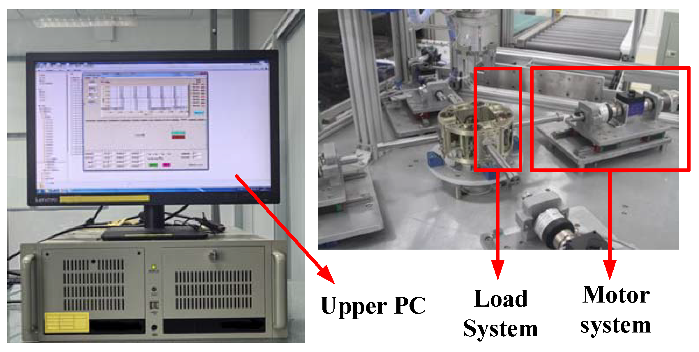
4. Experimental Testing and Validation

4.1. Nonlinear Identification

The picture of the experiment setup is shown in Figure 8. In Section 4.1, the nonlinear factors of friction, clearance and stiffness of the PMSM servo system for spacecraft are identified and combined into a complete nonlinear model.

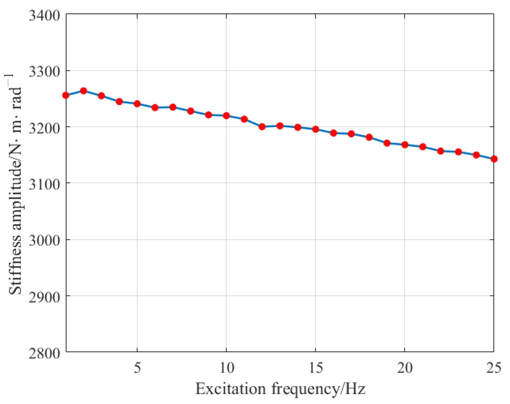
4.1.1. Elastic Model Parameter Identification

The stiffness of the spacecraft servo system is a complex number that varies with the excitation frequency, known as dynamic stiffness. The dynamic stiffness of the PMSM servo system of spacecraft refers to the dynamic torque required to generate a unit angle at the output end of the steering gear, which reflects the characteristic that the support stiffness will change with the frequency of the external load. The dynamic stiffness has a significant influence on the vibration characteristics of the spacecraft servo system. Therefore, fine modeling and dynamic stiffness simulation analysis of the spacecraft servo system are very necessary.
The method to obtain the dynamic stiffness in the elastic model involves maintaining a constant setpoint angle, applying a sinusoidal torque excitation to the output shaft of the servo system, and simultaneously measuring the magnitude of the excitation torque and the response of the output shaft. These data are then used for frequency response analysis to calculate the magnitude and phase of the system stiffness. For n sampling points, a set of overdetermined equations can be formulated as follows:
Ku = f
where K = a sin ( ω i t 1 ) a cos ( ω i t 1 ) a sin ( ω i t 2 ) a cos ( ω i t 2 ) a sin ( ω i t n ) a cos ( ω i t n ) , u = A i cos ϕ i A i sin ϕ i , f = y i ( t 1 ) y i ( t 2 ) y i ( t n ) , y i ( t ) = A i a sin ( ω i t + ϕ i ) . a is the amplitude of the excitation signal, ω i is the i-th frequency of the excitation signal, A i is the amplitude of the output signal, and ϕ i is the phase difference between the output signal and the input signal.
The least squares method is used to solve the overdetermined equation u = ( K T K ) 1 K T f , from which the frequency response function for the corresponding frequency is obtained:
G ( j ω i ) = A i cos ϕ i + j A i sin ϕ i
The dynamic stiffness of the servo system is the reciprocal of G ( j ω i ) .
Select a stepwise sinusoidal sweep excitation torque with an amplitude of 10 N · m from 1 to 25 Hz and measure the rotation angle response of the output shaft of the steering gear. Use the method described in this article to calculate the dynamic stiffness of the system, as shown in Figure 9. According to the experimental results, it can be seen that the stiffness changes slowly with the excitation frequency. The static stiffness is about 3270 N · m · rad 1 .

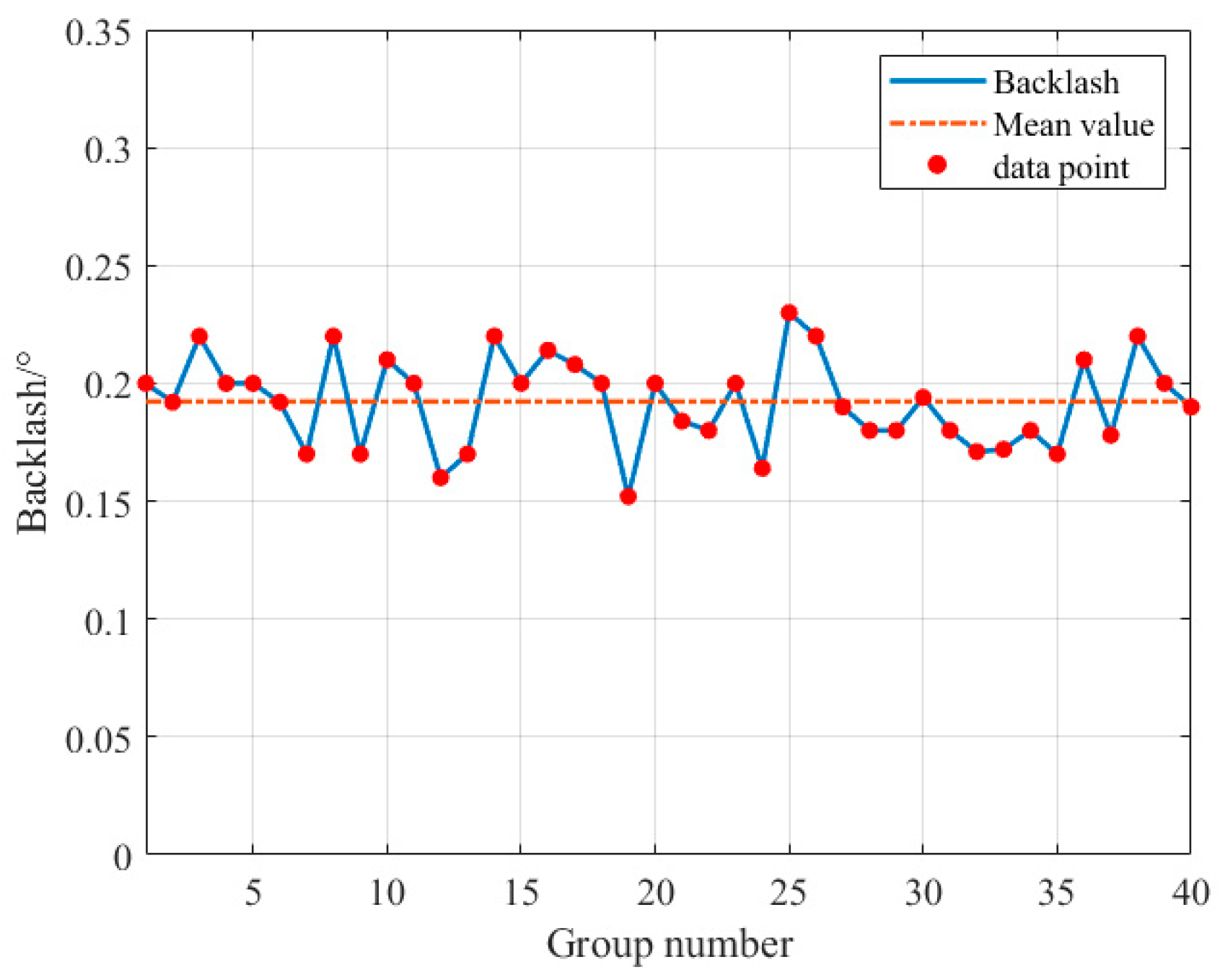
4.1.2. Dead-Zone Backlash Parameter Identification

The backlash is usually measured by measuring the angular position difference in the forward and reverse transition process when the steering gear is stopped. In this paper, another method is adopted, that is, the position feedback of commutation time is observed in the process of motor motion. Because of the backlash, the position feedback will have a larger delay in reversing, and the backlash of the system can be calculated by measuring this delay angle. The actual operation process is as follows.
Start the motor, when the motor is running steadily this indicates that the servo system has eliminated the unidirectional backlash. Immediately give the reverse angle command to reverse the motor. Due to the existence of transmission backlash, the actuator’s reverse angle lags behind the given angle. The width of the transmission backlash can be determined by comparing and analyzing the given angle and the actual feedback angle. The result of the backlash test is shown in Figure 10. According to the test results, the maximum backlash of the servo system output is 0.2300°, and the average backlash is 0.1923°. To evaluate the consistency of the test results, the standard deviation of these data is calculated to be 0.0193, which is within the acceptable range, indicating a good consistency of data. So, the backlash 2b = 0.1923°, and then the unilateral backlash b = 0.0962°.

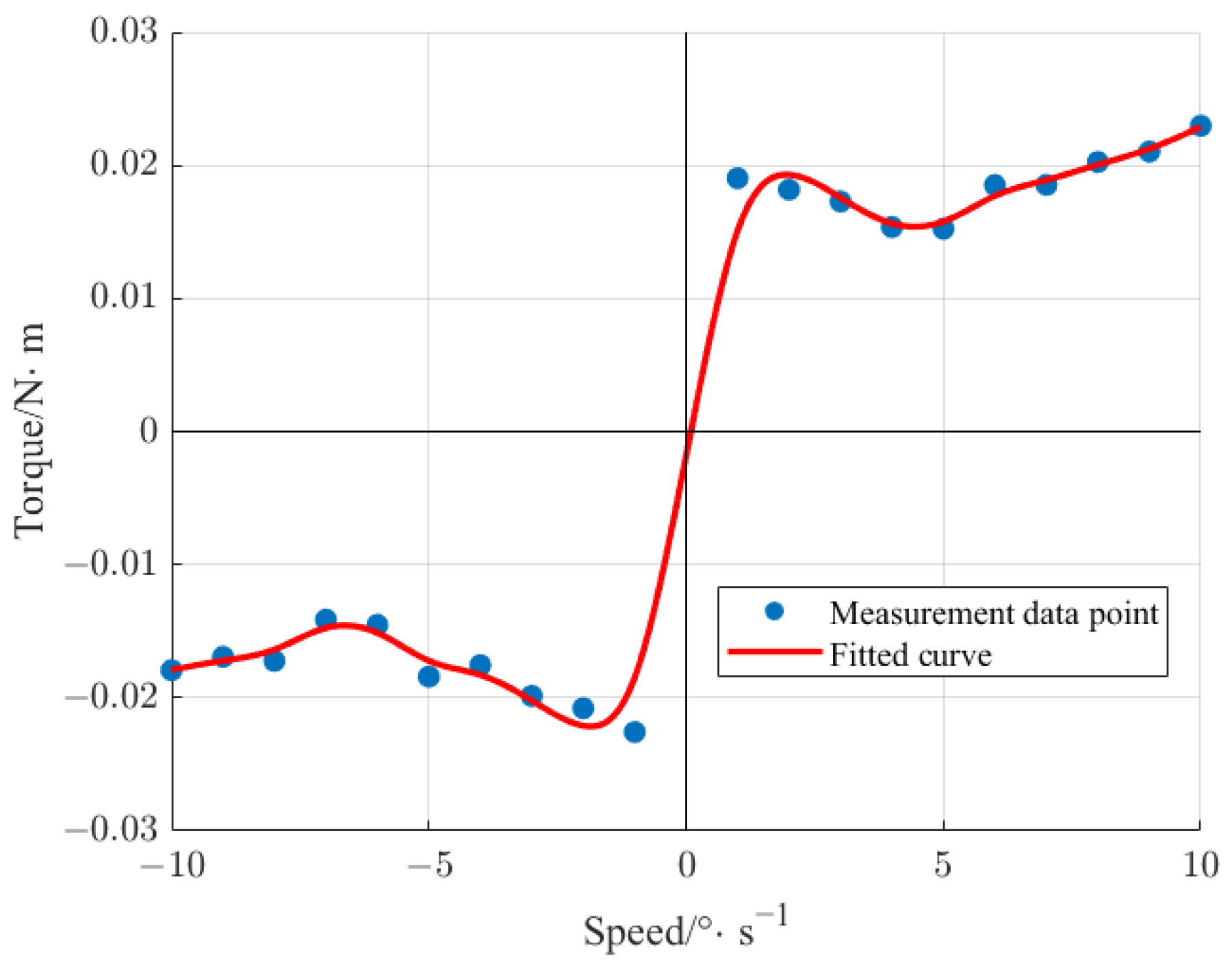
4.1.3. LuGre Friction Parameter Identification

Friction parameter identification is performed based on the LuGre friction model formulas (7) and (10). Since the state is relatively stable in a ground test environment, μ = λ = 1 is taken. The static parameters F c , F s , θ ˙ s , and σ 2 of the LuGre model can be identified through offline experiments. When the servo system is operating in a steady-state, we have z ˙ = 0 , and according to Formula (7), the friction force under steady-state can be obtained as follows:
F s f = F c + ( F s F c ) exp ( θ ˙ / θ ˙ s ) 2 sgn ( θ ˙ ) + σ 2 θ ˙
By measuring the q-axis current signal of the servo system at steady-state operating speeds multiple times, multiplying the current by the torque coefficient yields the corresponding torque. The velocity–torque curve is fitted using the least squares method, and finally, the steady-state friction parameters are obtained according to Equation (13). The experiment measured the motor torque changes at different speeds from 1 ° · s 1 to 10 ° · s 1 in the forward and reverse directions, as shown in Figure 11. The friction model curve is fitted according to the measured points, as shown by the red line in the figure. The RMSE (Root Mean Squared Error) of the data points and fitted values is calculated to be 1.415 × 10⁻³. The static parameters calculated by Formula (13) are presented in Table 1.
When the system is in critical or low-speed motion, it is mainly affected by Coulomb friction. At this time, there is an approximate relationship where z θ and d z / d t θ ˙ . Substituting these values into Formula (7) yields:
F d f = σ 0 θ + ( σ 1 + σ 2 ) θ ˙
Based on the specific characteristics of the servo system, and the dynamic equations involving electromagnetic torque, load torque, and moment of inertia, the following Laplace transform can be obtained:
θ m ( s ) i ( s ) = K t J m s 2 + ( σ 1 + σ 2 ) s + σ 0
where K t is the torque coefficient. By setting ω n = σ 0 / J m and ξ = σ 1 + σ 2 2 σ 0 J m , we can obtain the transfer function of the second-order system:
θ m ( s ) i ( s ) = ω n 2 s 2 + 2 ξ ω n s + ω n 2 K t σ 0
According to the unit step response characteristics of the second-order system
x 0 ( t ) = 1 exp ( ξ ω n t ) 1 ξ 2 sin ω d t + arctan 1 ξ 2 ξ ω d = ω n 1 ξ 2
where x 0 ( t ) represents the output of the unit step response at time t .
By inputting a low-amplitude current step signal and collecting the response curve, ω n and ξ can be obtained, and then the values of σ 0 and σ 1 can be calculated. The dynamic parameters obtained from the experiment are shown in Table 2.

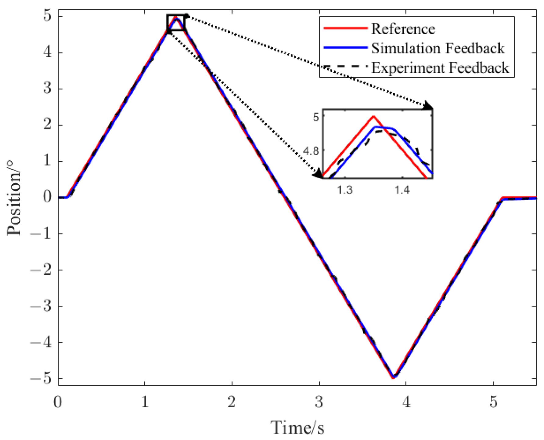
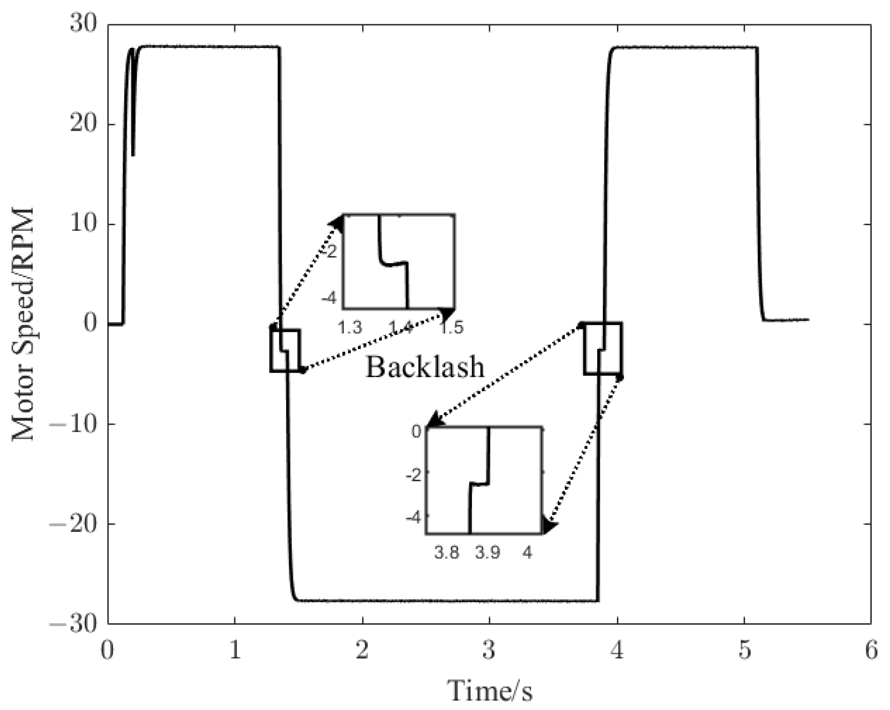
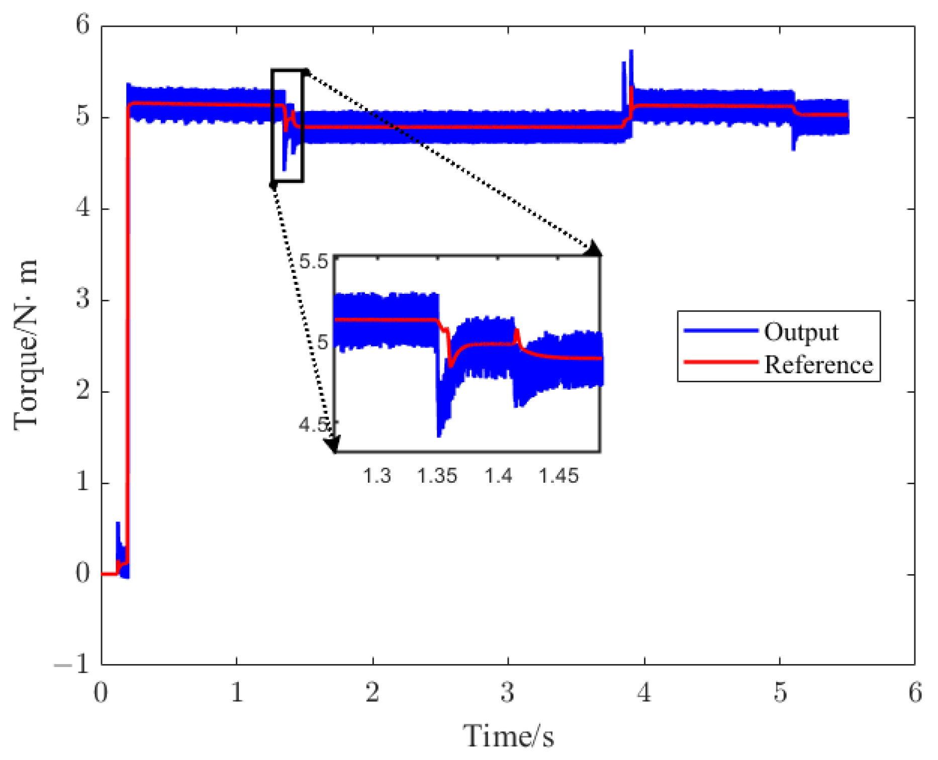
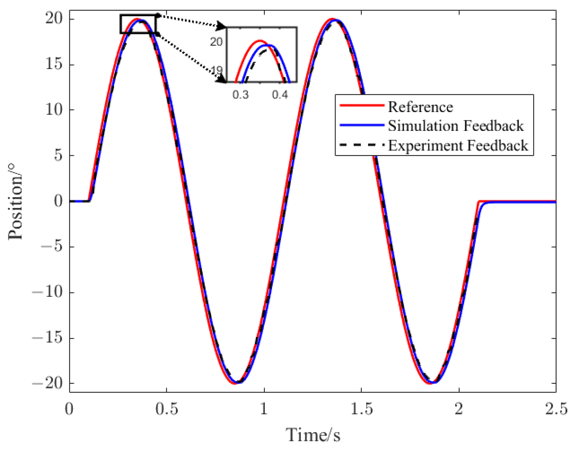
4.2. Servo System Verification

In order to verify the theoretical analysis mentioned above, experimental verification was conducted in a certain spacecraft servo system. The system parameters used in the experimental testing were identical to those used in the simulation. Different amplitude and frequency triangular and sinusoidal tracking signals were applied during the experiments, and the experimental results are shown in Figure 12, Figure 13, Figure 14 and Figure 15.
Apply a triangle wave position command with a period of 5 s and an amplitude of 5° to the servo system and run it for one cycle. The reference position of the servo system and the position response are shown in Figure 12. The figure also compares the experimental results, as shown by the black dashed line. It can be seen that when the triangular wave is in peak commutation, the presence of backlash leads to the dead zone. The simulation results are consistent with the experimental results.
Figure 12. Simulation and experimental position waveforms under triangular wave position instruction.
Applsci 14 01161 g012
Figure 13 shows the speed of the motor. When the position is in the rising or falling stage of the triangle wave, the motor in the servo system moves at a constant speed. There is also the influence of the backlash at the time of speed reversal, which is zoomed out in Figure 13.
Figure 13. Speed of the motor in the servo system.
Applsci 14 01161 g013
The servo system applies a nominal load of 5 N · m at 0.2 s, and the red line in Figure 14 represents the reference torque of the servo system. Because the LuGre friction model and elastic-dead-zone model are modeled in the simulation, the reference input does not remain at 5 N · m after 0.2 s, but with small deviations. The blue line in Figure 15 represents the actual output torque of the motor, which is basically consistent with the reference value. At the motor commutation time of 1.35 s and 3.85 s, the torque output value and the reference value keep the same trend. There is a certain torque fluctuation compared to the reference torque.
Figure 14. Output and reference torque of the motor.
Applsci 14 01161 g014
Apply a sinusoidal wave position command with a period of 1 s and an amplitude of 20° to the servo system and run it for two cycles. The results are also in line with expectations. The red line in Figure 15 represents the reference position of the servo system. The position responses are represented by blue and black lines. The position response has a small flat top at the sinusoidal wave peak, which can prove that the backlash dead zone also exists at the time of reversal.
Figure 15. Simulation and experimental position waveforms under sinusoidal wave position instruction.
Applsci 14 01161 g015
Given the position instructions of the triangle wave and sinusoidal wave, the position feedback can be well-tracked and consistent with the experimental results, which verifies the correctness of the modeling. And the simulation model shows the impact of the two-mass elastic system with backlash and the friction model on the actual results.

5. Conclusions

In the context of difficulties in obtaining data and high verification costs for the PMSM servo system of spacecraft in real-world scenarios, a theoretical model of the spacecraft PMSM servo system was established based on the characteristics of elasticity, backlash, and friction. Based on the control principle of PMSM and mechanical transmission, the mechanism of three nonlinear factors in servo systems is described in detail, which can comprehensively characterize the impact of various nonlinear factors on the system. Based on the actual data, the use of sinusoidal sweep frequency and the least squares method for parameter identification greatly improves the accuracy of the model, making the output more closely related to the real situation. This can provide reliable and effective theoretical and technical support for the research on high-performance control methods and system optimization design.

Author Contributions

Conceptualization, Z.S., H.X. and X.X.; methodology, Z.S., H.X. and X.X.; validation, H.X., Z.S. and Y.M.; investigation, X.X.; resources, Y.M.; data curation, H.X., P.W. and W.Z.; writing—original draft preparation, Z.S., W.Z. and P.W.; writing—review and editing, H.X.; supervision, Z.S.; project administration, X.X. All authors have read and agreed to the published version of the manuscript.

Funding

This research was supported by the National Key Research and Development Program of China (2020YFE0205400), the National Natural Science Foundation of China (52337002 and 52305541).

Institutional Review Board Statement

Not applicable.

Informed Consent Statement

Not applicable.

Data Availability Statement

The data are not publicly available due to copyright issues with co-developers. They are restricted to the experimental results.

Conflicts of Interest

The authors declare no conflicts of interest.

References

  1. Wang, C.; Yang, M.; Luan, T.; Xu, D. Review on Identification of External Mechanical Parameters of Two-Mass Elastic Servo System. Proc. CSEE 2016, 36, 804–817. [Google Scholar]
  2. Padron, J.; Yokokura, Y.; Ohishi, K.; Miyazaki, T.; Kawai, Y. Evaluating the Equivalence between Nonlinear Friction and Backlash in Two-Inertia Systems. In Proceedings of the 2022 IEEE 17th International Conference on Advanced Motion Control (AMC), Padova, Italy, 18–20 February 2022; pp. 335–340. [Google Scholar]
  3. Nowopolski, K.; Wicher, B.; Zawirski, K.; Tułodziecki, M. Control of Electromechanical Object with Backlash and Elasticity within Interconnection between Motor and Load. In Proceedings of the 2015 Selected Problems of Electrical Engineering and Electronics (WZEE), Kielce, Poland, 17–19 September 2015; pp. 1–6. [Google Scholar]
  4. Jiao, Z.; Chen, X.; Liu, X.; Li, X.; Qi, P.; Shang, Y.; Qiao, W. An Experimental Study on Outer Frame Position Control of Hydraulic Flight Motion Simulator with Model Compensation. IEEE/ASME Trans. Mechatron. 2022, 27, 3419–3428. [Google Scholar] [CrossRef]
  5. Santos Ballesteros, H.M.; das Neves Calvo, R.; Filho, A.A. Dynamic Stiffness Enhancement of a Flight Control Actuator Using Control Techniques. In Proceedings of the 2017 IEEE International Conference on Mechatronics (ICM), Churchill, Australia, 13–15 February 2017; pp. 260–265. [Google Scholar]
  6. Chuthai, T.; Cole, M.O.T.; Wongratanaphisan, T.; Puangmali, P. Adaptive Kinematic Mapping Based on Chebyshev Interpolation: Application to Flexure-Jointed Micromanipulator Control. IEEE/ASME Trans. Mechatron. 2020, 25, 118–129. [Google Scholar] [CrossRef]
  7. Li, K.; Wang, H.; Liang, X.; Miao, Y. Visual Servoing of Flexible-Link Manipulators by Considering Vibration Suppression Without Deformation Measurements. IEEE Trans. Cybern. 2022, 52, 12454–12463. [Google Scholar] [CrossRef] [PubMed]
  8. Gao, H.; He, W.; Zhou, C.; Sun, C. Neural Network Control of a Two-Link Flexible Robotic Manipulator Using Assumed Mode Method. IEEE Trans. Ind. Inform. 2019, 15, 755–765. [Google Scholar] [CrossRef]
  9. Masoud, A.E.; Maas, J. Limit Cycle Analysis for Drive Systems with Backlash Nonlinearity Using an Eigenvalue Method. In Proceedings of the 2019 IEEE/ASME International Conference on Advanced Intelligent Mechatronics (AIM), Hong Kong, China, 8–12 July 2019; pp. 1409–1414. [Google Scholar]
  10. Yang, M.; Wang, C.; Xu, D.; Zheng, W.; Lang, X. Shaft Torque Limiting Control Using Shaft Torque Compensator for Two-Inertia Elastic System with Backlash. IEEE/ASME Trans. Mechatron. 2016, 21, 2902–2911. [Google Scholar] [CrossRef]
  11. Shi, Z.; Zuo, Z. Backstepping Control for Gear Transmission Servo Systems with Backlash Nonlinearity. IEEE Trans. Autom. Sci. Eng. 2015, 12, 752–757. [Google Scholar] [CrossRef]
  12. Wang, C.; Yang, M.; Zheng, W.; Hu, K.; Xu, D. Analysis and Suppression of Limit Cycle Oscillation for Transmission System with Backlash Nonlinearity. IEEE Trans. Ind. Electron. 2017, 64, 9261–9270. [Google Scholar] [CrossRef]
  13. Wicher, B.; Brock, S. Tuning Optimization of Extended State Observer for Two Mass System with Elastic Joint and Backlash. In Proceedings of the 2018 18th International Conference on Mechatronics—Mechatronika (ME), Brno, Czech Republic, 5–7 December 2018; pp. 1–6. [Google Scholar]
  14. Phuong, T.H.; Belov, M.P.; Thuy, D.V. Adaptive Model Predictive Control for Nonlinear Elastic Electrical Transmission Servo Drives. In Proceedings of the 2019 IEEE Conference of Russian Young Researchers in Electrical and Electronic Engineering (EIConRus), Saint Petersburg and Moscow, Russia, 28–31 January 2019; pp. 704–708. [Google Scholar]
  15. Peng, J.; Wang, C.; Zheng, W.; Pan, J.; Liu, F.; Yang, J. Compound Mechanism Analysis of Backlash and Friction Nonlinearity in Full-Closed-Loop Servo Drive System. In Proceedings of the 2021 IEEE 7th International Conference on Control Science and Systems Engineering (ICCSSE), Qingdao, China, 30 July–1 August 2021; pp. 130–135. [Google Scholar]
  16. Liu, D.; Liu, H.; He, Y.; Zhang, B.; Liu, Y.; Li, Z.; Luo, C. Research on Flexible Joint Friction Identification of Space Lab Manipulator. In Proceedings of the 2018 IEEE International Conference on Mechatronics and Automation (ICMA), Piscataway, NJ, USA, 5–8 August 2018; pp. 614–619. [Google Scholar]
  17. Wang, S.; Na, J. Parameter Estimation and Adaptive Control for Servo Mechanisms with Friction Compensation. IEEE Trans. Ind. Inform. 2020, 16, 6816–6825. [Google Scholar] [CrossRef]
  18. Thenozhi, S.; Sánchez, A.C.; Rodríguez-Reséndiz, J. A Contraction Theory-Based Tracking Control Design with Friction Identification and Compensation. IEEE Trans. Ind. Electron. 2022, 69, 6111–6120. [Google Scholar] [CrossRef]
  19. Zhu, M.; Liu, A.; Gao, S.; Gao, Q. Linearization Design of Servo System and Parameter Identification Based on LuGre Model. In Proceedings of the 2021 IEEE 16th Conference on Industrial Electronics and Applications (ICIEA), Chengdu, China, 1–4 August 2021; pp. 1944–1947. [Google Scholar]
  20. Park, S.-H.; Park, J.-C.; Lee, H.-Y.; Kwon, S.-O.; Lim, M.-S. Design of High-Bandwidth Motor System Considering Electrical and Mechanical Time Constants. IEEE Trans. Ind. Appl. 2020, 56, 4738–4747. [Google Scholar] [CrossRef]
  21. Yao, J.; Deng, W.; Jiao, Z. Adaptive Control of Hydraulic Actuators with LuGre Model-Based Friction Compensation. IEEE Trans. Ind. Electron. 2015, 62, 6469–6477. [Google Scholar] [CrossRef]
  22. Wang, C.; Peng, J.; Pan, J. A Novel Friction Compensation Method Based on Stribeck Model with Fuzzy Filter for PMSM Servo Systems. IEEE Trans. Ind. Electron. 2023, 70, 12124–12133. [Google Scholar] [CrossRef]
  23. Sun, L.; Li, X.; Chen, L.; Shi, H.; Jiang, Z. Dual-Motor Coordination for High-Quality Servo with Transmission Backlash. IEEE Trans. Ind. Electron. 2023, 70, 1182–1196. [Google Scholar] [CrossRef]
  24. Lukichev, D.V.; Demidova, G.L.; Brock, S. Fuzzy Adaptive PID Control for Two-Mass Servo-Drive System with Elasticity and Friction. In Proceedings of the 2015 IEEE 2nd International Conference on Cybernetics (CYBCONF), Gdynia, Poland, 24–26 June 2015; pp. 443–448. [Google Scholar]
Figure 1. The structure of PMSM servo system for spacecraft.
Applsci 14 01161 g001
Figure 2. The structural diagram of the whole servo system.
Applsci 14 01161 g002
Figure 3. Two-mass elastic model.
Applsci 14 01161 g003
Figure 4. Block diagram of two-mass elastic system.
Applsci 14 01161 g004
Figure 5. Dead-zone characteristics of the backlash.
Applsci 14 01161 g005
Figure 6. Block diagram of the two-mass elastic system with backlash.
Applsci 14 01161 g006
Figure 8. Picture of the experimental setup.
Applsci 14 01161 g008
Figure 9. Dynamic stiffness of the servo system.
Applsci 14 01161 g009
Figure 10. Backlash of the servo system.
Applsci 14 01161 g010
Figure 11. Fitting curve of LuGre friction model.
Applsci 14 01161 g011
Table 1. Static parameters of LuGre friction model.
Static parameters F s / N · m F c / N · m θ ˙ s / rad · s 1 σ 2 / N · m · rad 1
0.0240.0113.73 7.53 × 10 4
Table 2. Dynamic parameters of LuGre friction model.
Dynamic parameters σ 0 / N · m · rad 1 σ 1 / N · m · s · rad 1
1.40.051
Disclaimer/Publisher’s Note: The statements, opinions and data contained in all publications are solely those of the individual author(s) and contributor(s) and not of MDPI and/or the editor(s). MDPI and/or the editor(s) disclaim responsibility for any injury to people or property resulting from any ideas, methods, instructions or products referred to in the content.

